JP4276813B2 - Heat treatment apparatus and semiconductor manufacturing method - Google Patents
Heat treatment apparatus and semiconductor manufacturing method Download PDFInfo
- Publication number
- JP4276813B2 JP4276813B2 JP2002085137A JP2002085137A JP4276813B2 JP 4276813 B2 JP4276813 B2 JP 4276813B2 JP 2002085137 A JP2002085137 A JP 2002085137A JP 2002085137 A JP2002085137 A JP 2002085137A JP 4276813 B2 JP4276813 B2 JP 4276813B2
- Authority
- JP
- Japan
- Prior art keywords
- boat
- heater
- processing chamber
- sub
- wafer
- Prior art date
- Legal status (The legal status is an assumption and is not a legal conclusion. Google has not performed a legal analysis and makes no representation as to the accuracy of the status listed.)
- Expired - Lifetime
Links
Images


Classifications
-
- H—ELECTRICITY
- H01—ELECTRIC ELEMENTS
- H01L—SEMICONDUCTOR DEVICES NOT COVERED BY CLASS H10
- H01L21/00—Processes or apparatus adapted for the manufacture or treatment of semiconductor or solid state devices or of parts thereof
- H01L21/67—Apparatus specially adapted for handling semiconductor or electric solid state devices during manufacture or treatment thereof; Apparatus specially adapted for handling wafers during manufacture or treatment of semiconductor or electric solid state devices or components ; Apparatus not specifically provided for elsewhere
- H01L21/673—Apparatus specially adapted for handling semiconductor or electric solid state devices during manufacture or treatment thereof; Apparatus specially adapted for handling wafers during manufacture or treatment of semiconductor or electric solid state devices or components ; Apparatus not specifically provided for elsewhere using specially adapted carriers or holders; Fixing the workpieces on such carriers or holders
- H01L21/67303—Vertical boat type carrier whereby the substrates are horizontally supported, e.g. comprising rod-shaped elements
-
- C—CHEMISTRY; METALLURGY
- C30—CRYSTAL GROWTH
- C30B—SINGLE-CRYSTAL GROWTH; UNIDIRECTIONAL SOLIDIFICATION OF EUTECTIC MATERIAL OR UNIDIRECTIONAL DEMIXING OF EUTECTOID MATERIAL; REFINING BY ZONE-MELTING OF MATERIAL; PRODUCTION OF A HOMOGENEOUS POLYCRYSTALLINE MATERIAL WITH DEFINED STRUCTURE; SINGLE CRYSTALS OR HOMOGENEOUS POLYCRYSTALLINE MATERIAL WITH DEFINED STRUCTURE; AFTER-TREATMENT OF SINGLE CRYSTALS OR A HOMOGENEOUS POLYCRYSTALLINE MATERIAL WITH DEFINED STRUCTURE; APPARATUS THEREFOR
- C30B31/00—Diffusion or doping processes for single crystals or homogeneous polycrystalline material with defined structure; Apparatus therefor
- C30B31/06—Diffusion or doping processes for single crystals or homogeneous polycrystalline material with defined structure; Apparatus therefor by contacting with diffusion material in the gaseous state
- C30B31/10—Reaction chambers; Selection of materials therefor
-
- H—ELECTRICITY
- H01—ELECTRIC ELEMENTS
- H01L—SEMICONDUCTOR DEVICES NOT COVERED BY CLASS H10
- H01L21/00—Processes or apparatus adapted for the manufacture or treatment of semiconductor or solid state devices or of parts thereof
- H01L21/67—Apparatus specially adapted for handling semiconductor or electric solid state devices during manufacture or treatment thereof; Apparatus specially adapted for handling wafers during manufacture or treatment of semiconductor or electric solid state devices or components ; Apparatus not specifically provided for elsewhere
- H01L21/67005—Apparatus not specifically provided for elsewhere
- H01L21/67011—Apparatus for manufacture or treatment
- H01L21/67098—Apparatus for thermal treatment
- H01L21/67109—Apparatus for thermal treatment mainly by convection
Landscapes
- Engineering & Computer Science (AREA)
- Microelectronics & Electronic Packaging (AREA)
- Condensed Matter Physics & Semiconductors (AREA)
- General Physics & Mathematics (AREA)
- Manufacturing & Machinery (AREA)
- Computer Hardware Design (AREA)
- Physics & Mathematics (AREA)
- Power Engineering (AREA)
- Chemical & Material Sciences (AREA)
- Crystallography & Structural Chemistry (AREA)
- Materials Engineering (AREA)
- Metallurgy (AREA)
- Organic Chemistry (AREA)
Description
【0001】
【発明の属する技術分野】
本発明は、熱処理技術、特に、被処理物を処理室に収容してヒータによって加熱した状態で処理を施す熱処理技術に関し、例えば、半導体集積回路装置(以下、ICという。)が作り込まれる半導体ウエハ(以下、ウエハという。)に酸化処理や拡散処理、イオン打ち込み後のキャリア活性化や平坦化のためのリフローやアニールおよび熱CVD反応による成膜処理等(以下、熱処理という。)に使用される熱処理装置(furnace )に利用して有効なものに関する。
【0002】
【従来の技術】
ICの製造方法におけるウエハの熱処理には、バッチ式縦形ホットウオール形熱処理装置(以下、縦形熱処理装置という。)が、広く使用されている。縦形熱処理装置は、ウエハが搬入される処理室を形成するインナチューブおよびこのインナチューブを取り囲むアウタチューブから構成され縦形に設置されたプロセスチューブと、プロセスチューブの外部に敷設されてプロセスチューブ内を加熱するヒータとを備えており、複数枚のウエハがボートによって長く整列されて保持された状態でインナチューブ内に下端の炉口から搬入(ボートローディング)され、ヒータによって処理室が加熱されることにより、ウエハに熱処理が施されるように構成されている。
【0003】
従来のこの種の縦形熱処理装置として、熱放出量の大きい処理室の下部に補助加熱用のサブヒータを設置して短時間で処理室の垂直方向の温度の回復と安定とを確保することにより、ウエハの処理時間の短縮を図ったものがある。しかしながら、この縦形熱処理装置においては、ボートを回転することができないため、ウエハ面内の膜厚の均一性の低下を招くという問題点がある。そこで、垂直方向の温度の安定を確保しつつウエハ面内の温度分布の均一性も確保するために、例えば、特開2001−156005号公報および特開2001−210631号公報には、サブヒータを装備しつつボートが回転可能な縦形熱処理装置が、提案されている。
【0004】
すなわち、前者には次のような縦形熱処理装置が開示されている。反応容器(プロセスチューブ)の下端を塞ぐ蓋体(シールキャップ)と保持具(ボート)との間には保温ユニットが蓋体に固定されて設置されており、この保温ユニットの中央部には保持具を回転させるための回転軸が貫通されている。保温ユニットの上面部には発熱体ユニット(サブヒータ)が設置されており、発熱体ユニットの給電路部材は回転軸の中心線上に敷設されている。
【0005】
また、後者には次のような縦形熱処理装置が開示されている。ボートを回転させるターンテーブルの上に保温筒が設置されており、サブヒータが保温筒の上部に面状に形成されている。
【0006】
【発明が解決しようとする課題】
しかしながら、特開2001−156005号公報の縦形熱処理装置には、次のような問題点がある。サブヒータの中央部にボート回転軸を挿通させるための貫通孔が開設された状態になることにより、サブヒータはボート上のウエハの中央部を加熱することができなくなるため、ウエハ面内の温度分布の均一性が低下してしまう。また、ボート回転軸は保温筒の内部を貫通させてボートを支持する状態になるため、ボート回転軸が細長くなり、重いボートを安定して支持することができない。そこで、ボート回転軸を太くすると、ウエハ面内の温度分布の均一性が低下してしまう。
【0007】
他方、特開2001−210631号公報の縦形熱処理装置においては、保温筒が回転する構造になっているため、スリップリング等が必要になるという問題点がある。
【0008】
本発明の目的は、従来の技術のこれらの問題点を解決し、垂直方向の温度の安定を確保しつつ水平面内の温度分布の均一性も確保することができる熱処理装置を提供することにある。
【0009】
【課題を解決するための手段】
前記した課題を解決するための手段は、処理室を形成し縦形に設置されたプロセスチューブと、このプロセスチューブの外部に敷設されて前記処理室を加熱するヒータと、複数枚の被処理基板を保持して前記処理室に搬入搬出するボートと、このボートを回転させるボート回転装置とを備えており、
前記ボート回転装置は固定された内軸とこの内軸に同心円に配置されて回転される外軸とを備えており、前記内軸の上端にはサブヒータが設置され、前記外軸には前記ボートと断熱部とが設置されていることを特徴とする。
【0010】
前記した手段によれば、サブヒータは固定軸である内軸の上端に設置されているため、ボートに水平に保持された被処理基板の全面を均一に加熱することができ、また、サブヒータの給電配線はスリップリングを要せずに電源に接続することができる。他方、ボートを回転させる外軸は外径を大きく設定することができるため、重量の大きいボートであっても安定して回転させることができる。
【0011】
【発明の実施の形態】
以下、本発明の一実施の形態を図面に即して説明する。
【0012】
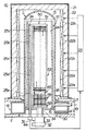
本実施の形態において、図1に示されているように、本発明に係る熱処理装置は、ICの製造方法における熱処理工程を実施する縦形熱処理装置(バッチ式縦形熱処理装置)10として構成されている。縦形熱処理装置10は中心線が垂直になるように縦に設置されたプロセスチューブ11を備えており、プロセスチューブ11はインナチューブ12とアウタチューブ13とから構成されている。インナチューブ12は石英ガラスまたは炭化シリコン(SiC)が使用されて円筒形状に一体成形され、アウタチューブ13は石英ガラスが使用されて円筒形状に一体成形されている。インナチューブ12は上下両端が開口した円筒形状に形成されており、インナチューブ12の筒中空部はボートによって長く整列した状態に保持された複数枚のウエハが搬入される処理室14を形成している。インナチューブ12の下端開口はウエハを出し入れするための炉口15を構成しており、インナチューブ12の内径は取り扱うウエハの最大外径(例えば、三百mm)よりも大きくなるように設定されている。
【0013】
アウタチューブ13は内径がインナチューブ12の外径よりも大きく上端が閉塞し下端が開口した円筒形状に形成されており、インナチューブ12にその外側を取り囲むように同心円に被せられている。インナチューブ12とアウタチューブ13との間の下端部は多段の円筒形状に構築されたマニホールド16によって気密封止されており、マニホールド16はインナチューブ12およびアウタチューブ13の交換等のためにインナチューブ12およびアウタチューブ13にそれぞれ着脱自在に取り付けられている。マニホールド16が縦形熱処理装置10の筐体(一部のみが図示されている。)2に支持されることにより、プロセスチューブ11は垂直に据え付けられた状態になっている。
【0014】
マニホールド16の側壁の上部には排気管17が接続されており、排気管17は排気装置(図示せず)に接続されてプロセスチューブ11の内部を排気し得るようになっている。排気管17はインナチューブ12とアウタチューブ13との間に形成された隙間に連通した状態になっており、インナチューブ12とアウタチューブ13との隙間によって排気路18が、横断面形状が一定幅の円形リング形状に構成されている。排気管17がマニホールド16に接続されているため、排気管17は円筒形状の中空体を形成されて垂直に延在した排気路18の最下端部に配置された状態になっている。また、マニホールド16の側壁の下部にはガス導入管19がインナチューブ12の炉口15に連通するように接続されており、ガス導入管19には原料ガス供給装置やキャリアガス供給装置およびパージガス供給装置(いずれも図示せず)が接続されている。ガス導入管19によって炉口15に導入されたガスはインナチューブ12の処理室14を流通して排気路18を通って排気管17によって外部へ排気されるようになっている。
【0015】
図1に示されているように、プロセスチューブ11の外側は断熱槽21によって全体的に被覆されており、断熱槽21の内側にはプロセスチューブ11の内部を加熱するヒータ22が、アウタチューブ13の周囲を包囲するように同心円に設備されている。断熱槽21はステンレス鋼等の薄板から円筒形状に形成されたカバーの内部にガラスウール等の断熱材が封入されて、プロセスチューブ11の外径よりも大径で長さが同程度の円筒形状に形成されており、筐体2に支持されることによって垂直に据え付けられている。ヒータ22はニクロム線等の線形の電気抵抗体によって形成されて、断熱槽21の内周面に螺旋状に巻装されている。ヒータ22は上側から順に、第一ヒータ部22a、第二ヒータ部22b、第三ヒータ部22c、第四ヒータ部22dおよび第五ヒータ部22eに五分割されており、これらヒータ部22a〜22eは温度コントローラ23によって互いに連携および独立してシーケンス制御されるように構成されている。
【0016】
図1に示されているように、シールキャップ30の外周辺部の一箇所には保護管24がボート50に干渉しないように上下方向に貫通されて垂直に固定されており、ボート50の処理室14への搬入時には、保護管24はインナチューブ12の内周面とボート50の外周面との間に位置する状態になっている。保護管24には五本の熱電対25a、25b、25c、25dおよび25eが纏めて封入されている。五本の熱電対25a、25b、25c、25dおよび25eは温度コントローラ23にそれぞれ接続されており、各熱電対25a〜25eは温度計測結果を温度コントローラ23にそれぞれ送信するようになっている。温度コントローラ23は各熱電対25a〜25eからの計測温度に基づいて各ヒータ部22a〜22eをフィードバック制御するようになっている。すなわち、温度コントローラ23は各ヒータ部22a〜22eの目標温度と各熱電対25a〜25eの計測温度との誤差を求めて、誤差がある場合には誤差を解消させるフィードバック制御を実行するようになっている。
【0017】
図1に示されているように、シールキャップ30はマニホールド16の下端開口を垂直方向下側から開閉するように構成されている。すなわち、シールキャップ30はマニホールド16の内径以上の外径を有する円盤形状に構築されており、プロセスチューブ11の外部に垂直に設備されたボートエレベータ(図示せず)によって垂直方向に昇降されるように構成されている。シールキャップ30の中心線上にはボート50を回転させるボート回転装置31が設置されている。
【0018】
図2および図3に詳示されているように、ボート回転装置31は上端が開口で下端が閉塞の略円筒形状に形成されたハウジング32を備えており、ハウジング32はシールキャップ30の下面に同心円に配置されて固定されている。ハウジング32の内部には細長い円筒形状に形成された内軸33が垂直方向に配置されて、ハウジング32の閉塞壁によって固定的に支持されている。ハウジング32の内部には内軸33の外径よりも大径の円筒形状に形成された外軸34が同心円に配置されており、外軸34は内軸33との間に介設された上下で一対の内側ベアリング35、36と、ハウジング32との間に介設された上下で一対の外側ベアリング37、38とによって回転自在に支承されている。上側の内側ベアリング35の上には内側磁性流体シール39が設置されており、上側の外側ベアリング37の上には外側磁性流体シール40が設置されている。ハウジング32の閉塞壁下面には外軸34の下端部をシールするキャップ41が固定されている。外軸34の外周における上側の外側ベアリング37と下側の外側ベアリング38との間にはウオームホイール42が同心円に固定されており、ウオームホイール42には電動モータ44によって回転駆動されるウオーム軸43が噛合されている。
【0019】
内軸33の上端にはサブヒータ45が垂直に立脚されて固定されている。サブヒータ45はセラミックが使用されて垂直の支柱部46aと水平の収納部46bとを有する中空体に成形されたケース46を備えており、ケース46の垂直の支柱部46aの下端面が内軸33の上端面に当接されてボルト46cによって固定されている。ケース46の収納部46bはウエハ1の外径よりも若干小径の中空円盤形状に形成されており、支柱部46aの上端において同心円に配置されて水平に支持された状態になっている。収納部46bの内部には、金属汚染を防止可能な二珪化モリブデン等の抵抗発熱体が使用されて線形状に形成された抵抗発熱線(以下、ヒータ素線という。)47が、図3に示されているように多重の同心円形状に敷設されている。ヒータ素線47の両端部は収納部46bの中央部において垂直方向下向きに屈曲されて支柱部46aの内部に引き込まれるとともに、内軸33の上端部まで導出されており、その内軸33の上端部においてヒータ素線47の両端部には一対の給電配線48、48がジョイント49、49によってそれぞれ接続されている。給電配線48は内軸33の下端開口から外部へ引き出されて電源(図示せず)に接続されている。
【0020】
外軸34の上端部には外向きフランジ形状のボート受け部34aが水平に突設されており、ボート受け部34aの上にはボート50が垂直に設置されている。ボート50は上下で一対の端板51、52と、両端板51と52との間に架設されて垂直に配設された三本の保持部材53とを備えており、三本の保持部材53には多数条の保持溝54が長手方向に等間隔に配されて互いに対向して開口するように刻設されている。ボート50は三本の保持部材53の保持溝54の間にウエハ1の周辺部をそれぞれ挿入されることにより、複数枚のウエハ1を水平にかつ互いに中心を揃えた状態に整列させて保持するようになっている。
【0021】
図2および図3に示されているように、三本の保持部材53におけるサブヒータ45の収納部46bの下方に位置する複数段(本実施の形態では六段)の保持溝54の間には、石英が使用されてウエハ1の外径と略等しい外径の円板形状に形成された断熱板55がそれぞれ一枚ずつ挿入されている。図5に詳示されているように、各断熱板55には長孔形状の切欠部56が半径方向に切設されている。切欠部56の幅はサブヒータ45の支柱部46aを逃げ得るように支柱部46aの外径よりも若干大きく設定されており、切欠部56の長さは断熱板55の半径よりも幅の分だけ長くなるように設定されている。そして、六段の保持溝54の間にそれぞれ挿入された状態において、各段の断熱板55の切欠部56は互いに重なり合わないように周方向に互いにずらされている。このように各段の断熱板55の切欠部56が周方向にずらされていることにより、各段の断熱板55の切欠部56の悪影響が防止されている。これらの断熱板55によってボート50の下端部には断熱部が構成されている。
【0022】
次に、前記構成に係る縦形熱処理装置を使用した場合の本発明の一実施の形態であるICの製造方法の熱処理工程を説明する。
【0023】
予め、ボート50には被処理基板としてのウエハ1が複数枚、ウエハ移載装置(図示せず)によって装填される。図1に示されているように、複数枚のウエハ1を整列保持したボート50はシールキャップ30の上にウエハ1群が並んだ方向が垂直になる状態で載置され、ボートエレベータによって差し上げられてインナチューブ12の炉口15から処理室14に搬入(ボートローディング)されて行き、シールキャップ30に支持されたままの状態で処理室14に存置される。
【0024】
本実施の形態においては、ボート50が処理室14に搬入されて行く途中または搬入が完了した後に、電力がサブヒータ45のヒータ素線47に給電配線48、48によってそれぞれ供給されることにより、ボート50の下部領域に保持されたウエハ1群がサブヒータ45によって補助的に加熱される。また、電動モータ44やウオーム軸43およびウオームホイール42によって外軸34が回転駆動されることにより、ボート50がボート回転装置31によってウエハ1群および断熱板55に慣性力を付与しない程度の速度で緩やかに回転される。
【0025】
ここで、ボート50の処理室14への搬入途中または搬入後にサブヒータ45によって補助的に加熱を実行する理由を説明する。プロセスチューブ11の外部に敷設されて処理室14を全体的に加熱するヒータ(以下、メインヒータという。)22は、殆どの場合、予め設定した処理温度に速く到達するようにボート50の処理室14への搬入前に、例えば、処理温度よりも150℃〜200℃程度低いスタンバイ温度で処理室14を加熱している。したがって、ボート50の上部領域のウエハ1群は下部領域のウエハ1群と比べて早くスタンバイ温度の処理室14へ搬入されることになる。その結果、上部領域のウエハ1と下部領域のウエハ1との間では熱履歴が相違してしまうため、同一の縦形熱処理装置10によって熱処理したにもかかわらず、ボート50の全長では熱処理の状態が相違してしまう。そこで、本実施の形態においては、ボート50の処理室14への搬入途中または搬入後にサブヒータ45による加熱を実行して、ボート50の下部領域のウエハ1群を下方から補助的に加熱することにより、上部領域のウエハ1と下部領域のウエハ1との間での熱履歴を一致させる制御を実行している。ちなみに、サブヒータ45による加熱開始のタイミングは、ボート50の処理室14への搬入速度や処理室14の内外の温度差等に依存する上部領域のウエハ1と下部領域のウエハ1との間での熱履歴の差異に対応して適宜に選定することが望ましい。
【0026】
このボート50の下部領域のウエハ1群を下方から加熱するサブヒータ45のヒータ素線47は支柱部46aの上端に水平に支持された収納部46bに全体にわたって同心円状に敷設されているため、ウエハ1の面内を全体にわたって均一に加熱する。この際、ヒータ素線47の両端部は中心において下方に屈曲されて支柱部46aにも敷設された状態になっているため、ウエハ1の面内の中央部も効果的に加熱することができる。ちなみに、ヒータ素線47の両端部が内軸33の内部に引き込まれてジョイント49によって給電配線48に接続されているため、給電配線48およびジョイント49は処理室14の高温雰囲気から内軸33によって保護された状態になっている。
【0027】
また、サブヒータ45は固定軸である内軸33に支持され、ボート50は回転軸である外軸34に支持されているため、サブヒータ45はウエハ1の面内の周方向について均一に加熱することになる。この際、サブヒータ45のケース46の収納部46bの外径はウエハ1の外径よりも小径に設定されているため、ボート回転装置31によるボート50の回転すなわち三本の保持部材53の公転と干渉することはない。また、ボート50の三本の保持部材53に保持された複数枚の断熱板55もボート50と共に回転することになるが、断熱板55の切欠部56の幅はサブヒータ45の支柱部46aの外径よりも大きく設定されているため、サブヒータ45に干渉することはない。ちなみに、内軸33の外側で回転する外軸34は大径に設定することができるため、重量の大きいボート50であっても安定して支持するとともに、回転させることができる。
【0028】
ボート50の処理室14への搬入が完了したら、プロセスチューブ11の内部が排気管17によって排気されるとともに、プロセスチューブ11の内部が予め設定された処理温度すなわち温度コントローラ23のシーケンス制御の目標温度(例えば、600〜1300℃)にメインヒータ22の各ヒータ部22a〜22eによって加熱される。この際、メインヒータ22の各ヒータ部22a〜22eの加熱によるプロセスチューブ11の内部の実際の上昇温度と、各ヒータ部22a〜22eのシーケンス制御の目標温度との誤差は、各熱電対25a〜25eの測温結果に基づくフィードバック制御によってそれぞれ補正される。
【0029】
ところで、本実施の形態においては、処理室14の上下方向の温度分布の均一性を高めるために、メインヒータ22をヒータ部22a〜22eに五分割され、かつ、五本の熱電対25a〜25eを配置することにより、所謂ゾーン制御が実行されるように構成されている。そこで、例えば、下部領域のウエハ1群に対応した最下段の熱電対25eの計測温度とそれ以外の熱電対25a〜25dの計測温度との差が所定の期間以上一定の範囲になった際に、サブヒータ45によるボート50の下部領域のウエハ1群を下方から補助的に加熱する作動を自動的に停止させる制御を実行させることができる。
【0030】
以上の温度制御によって処理室14の全体が予め設定された処理温度に安定すると、処理ガスが処理室14へガス導入管19から導入される。処理室14に導入された処理ガスは処理室14を上昇した後にインナチューブ12の上端開口から排気路18へ流れ込み、排気路18を通じて排気管17から排気される。処理ガスは処理室14を流れる際に、ウエハ1群に接触することによりウエハ1の表面に熱処理を施す。この際、ウエハ1の面内の温度分布や熱処理状態の分布の均一性を高めるために、ボート50はボート回転装置31によって緩やかに回転され続ける。
【0031】
本実施の形態においては、ボート50の下端部領域であるサブヒータ45の下方には複数枚の断熱板55が水平に並べられて介設されていることにより、ボート50の下端部領域のウエハ1群はメインヒータ22によって加熱制御され難い炉口15から離間した状態になっているため、下端部領域のウエハ1群の温度のボート50の全体のウエハ1群に対する均一性は高くなる。ここで、各断熱板55には切欠部56がそれぞれ切設されているため、水平面内の温度分布が低下するが、各段の断熱板55における切欠部56は重なり合わないように周方向の位置をずらされてるため、ボート50の下端部領域のウエハ1群に対する断熱板55の切欠部56の存在の影響は解消される。
【0032】
熱処理がウエハ1群に実施されて予め設定された熱処理時間が経過すると、メインヒータ22のヒータ部22a〜22eの加熱作用が温度コントローラ33のシーケンス制御によって停止されて、プロセスチューブ11の内部の温度が予め設定されたスタンバイ温度に降下されて行く。この際も、メインヒータ22の各ヒータ部22a〜22eによる処理室14の実際の下降温度とシーケンス制御の目標温度との誤差は、各熱電対25a〜25eの測温結果に基づくフィードバック制御によってそれぞれ補正される。
【0033】
そして、予め設定されたスタンバイ温度になるか、または、予め設定された降温時間が経過すると、シールキャップ30が下降されて炉口15が開口されるとともに、ボート50に保持された状態でウエハ1群が炉口15からプロセスチューブ11の外部に搬出(ボートアンローディング)される。
【0034】
ここで、ボート50の処理室14からの搬出に際しては、ボート50の下部領域のウエハ1群が上部領域のウエハ1群と比べて早く処理室14へ搬出されることになるため、下部領域のウエハ1と上部領域のウエハ1との間では熱履歴が相違してしまう。そこで、本実施の形態においては、ボート50の処理室14への搬出途中または搬出開始以前においてサブヒータ45による加熱を実行して、ボート50の下部領域のウエハ1群を下方から補助的に加熱することにより、下部領域のウエハ1と上部領域のウエハ1との間での熱履歴を一致させる制御が実行される。ちなみに、サブヒータ45による加熱開始のタイミングは、ボート50の処理室14からの搬出速度や処理室14の内外の温度差等に依存する下部領域のウエハ1と上部領域のウエハ1との間での熱履歴の差異に対応して適宜に選定することが望ましい。
【0035】
ところで、最近は自然酸化膜がウエハに形成されるのを防止する方向に進んでおり、処理室の下に窒素雰囲気や真空雰囲気を形成するロードロックチャンバ等が設置されている。しかし、ロードロックチャンバ等が設置されていない場合には、処理室からのボートの搬出が始まると、ウエハは処理室外の雰囲気に晒されてしまうため、ウエハの表面に自然酸化膜が形成されてしまう。この際、搬出されるウエハの温度が高い程、自然酸化膜が形成され易い。そこで、サブヒータ45の加熱を停止してボート50の搬出を開始することが考えられる。ところが、サブヒータ45の加熱を停止してボート50の搬出を開始すると、ボート50の上部領域のウエハ1群と下部領域のウエハ1群との熱履歴が相違するため、上部領域のウエハ1群の自然酸化膜の形成具合と、下部領域のウエハ1群の自然酸化膜の形成具合との間でばらつきが発生してしまう。自然酸化膜の形成具合にばらつきが発生すると、それらウエハから取得されるIC(製品)の電気的特性に相違が発生してしまう等の問題点が派生する。つまり、自然酸化膜による影響抑制の観点からも、ボート50の処理室14への搬出途中または搬出開始以前においてサブヒータ45による加熱を実行して、ボート50の下部領域のウエハ1群を下方から補助的に加熱することにより、下部領域のウエハ1と上部領域のウエハ1との間での熱履歴を一致させる制御を実行することが望ましい。
【0036】
ボート50が処理室14から搬出されると、処理済のウエハ1群がボート50から脱装(ディスチャージ)される。以上の作用が繰り返されることにより、縦形熱処理装置による熱処理がウエハ1にバッチ処理されて行く。
【0037】
なお、繰り返し使用された断熱板55が処理ガスの反応生成物や未反応生成物の付着や堆積によって汚染された場合には、断熱板55はボート50およびサブヒータ45から取り外されて洗浄される。すなわち、断熱板55は切欠部56をサブヒータ45の支柱部46aに対して後退させるとともに、外周部をボート50の保持溝54から抜き出すことにより、容易に取り外すことができる。ちなみに、サブヒータ45はボルト46cの締結を解除することにより、内軸33から取り外すことができる。
【0038】
前記実施の形態によれば、次の効果が得られる。
【0039】
1) ボート回転装置に固定軸である内軸と回転軸である外軸とを設け、サブヒータを固定軸である内軸の上端に設置することにより、ボートに水平に保持されたウエハの全面を下方から均一に加熱することができるとともに、サブヒータの給電配線をスリップリングを要せずに電源に接続することができる。
【0040】
2) ボート回転装置に固定軸である内軸と回転軸である外軸とを設け、ボートおよび断熱部を外軸に設置することにより、外軸の外径を大きく設定することができるため、重量の大きいボートおよび断熱部であっても安定して回転させることができる。
【0041】
3) 前記1)および2)により、ボート上のウエハ群における垂直方向の温度の安定を確保しつつウエハ面内の温度分布の均一性も確保することができるため、縦形熱処理装置によるウエハの処理時間を短縮することができるとともに、処理精度や信頼性および製造歩留りを高めることができ、ひいては、ICの品質および信頼性を高めることができる。
【0042】
4) サブヒータのヒータ素線をケースの支柱部の上端に水平に支持された収納部に全体にわたって同心円状に敷設するとともに、ヒータ素線の両端部を中心において下方に屈曲して支柱部にも敷設することにより、ボートの下部領域のウエハの面内の中央部も効果的に加熱することができるため、ウエハ面内を全体にわたって均一に加熱することができる。
【0043】
5) ヒータ素線の両端部を内軸の内部に引き込んでジョイントによって給電配線に接続することにより、給電配線およびジョイントを処理室の高温雰囲気から内軸によって保護することができるため、給電配線やジョイントの寿命ひいてはサブヒータ全体としての寿命を延長することができる。
【0044】
6) ボートの下端部領域であるサブヒータの下方に複数枚の断熱板を水平に並べて介設することにより、ボートの下端部領域のウエハ群をメインヒータによって加熱制御され難い炉口から離間させることができるため、下端部領域のウエハ群の温度のボート全体のウエハ群に対する均一性を高めることができる。
【0045】
7) 断熱板にサブヒータの支柱部を逃げる切欠部を切設することにより、繰り返しの使用によって汚染された断熱板を交換したり洗浄によって再生使用したりすることができる。
【0046】
8) 各段の断熱板における切欠部を重なり合わないように周方向の位置をずらすことにより、ボートの下端部領域のウエハ群に対する断熱板の切欠部の存在の影響を解消することができるため、ボートの下端部領域のウエハにおける面内均一性を維持することができる。
【0047】
9) また、サブヒータを内軸に着脱自在に設置することにより、汚染されたサブヒータを交換したり洗浄によって再生使用したりすることができる。
【0048】
図6は本発明の第二の実施の形態である縦形熱処理装置の主要部を示す一部省略一部切断正面図である。
【0049】
本実施の形態が前記実施の形態と異なる点は、ボート回転装置31の外軸34の上には断熱筒57が設置されており、この断熱筒57の内部にはサブヒータ45および複数枚の断熱板55が収容され、断熱筒57の上にはボート50が設置されている点、である。
【0050】
本実施の形態によれば、サブヒータ45が断熱筒57によって被覆されているため、サブヒータ45の加熱効率が若干低下するが、処理ガスの反応生成物や未反応生成物によるサブヒータ45や断熱板55の汚染を防止することができるという効果を得ることができる。
【0051】
なお、本発明は前記実施の形態に限定されるものではなく、その要旨を逸脱しない範囲で種々に変更が可能であることはいうまでもない。
【0052】
例えば、メインヒータは五分割するに限らず、二〜四または六以上に分割してもよい。
【0053】
熱電対はメインヒータの分割数に対応して敷設するに限らず、メインヒータの分割数に対応せずに敷設してもよい。また、熱電対は処理室のウエハの近傍に配置するに限らず、インナチューブとアウタチューブとの間やプロセスチューブとヒータとの間に配置してもよい。
【0054】
熱処理は酸化処理や拡散処理および拡散だけでなくイオン打ち込み後のキャリア活性化や平坦化のためのリフローおよびアニール処理等に限らず、成膜処理等の熱処理であってもよい。
【0055】
被処理物はウエハに限らず、ホトマスクやプリント配線基板、液晶パネル、光ディスクおよび磁気ディスク等であってもよい。
【0056】
本発明は、バッチ式縦形熱処理装置に限らず、バッチ式縦形減圧CVD装置等の熱処理装置全般並びに半導体製造装置全般に適用することができる。
【0057】
【発明の効果】
本発明によれば、垂直方向の温度の安定を確保しつつ水平面内の温度分布の均一性も確保することができるため、熱処理装置による処理時間を短縮することができるとともに、半導体製造方法の処理精度や信頼性および製造歩留りを高めることができる。
【図面の簡単な説明】
【図1】本発明の一実施の形態であるバッチ式縦形熱処理装置を示す正面断面図である。
【図2】主要部を示す斜視図である。
【図3】その正面断面図である。
【図4】図3のIV−IV線に沿う平面断面図である。
【図5】複数枚の断熱板を示す分解斜視図である。
【図6】本発明の第二の実施の形態である縦形熱処理装置の主要部を示す一部省略一部切断正面図である。
【符号の説明】
1…ウエハ(被処理基板)、2…筐体、10…縦形熱処理装置(バッチ式縦形熱処理装置)、11…プロセスチューブ、12…インナチューブ、13…アウタチューブ、14…処理室、15…炉口、16…マニホールド、17…排気管、18…排気路、19…ガス導入管、21…断熱槽、22…ヒータ、22a〜22e…ヒータ部、23…温度コントローラ、24…保護管、25a〜25e…熱電対、30…シールキャップ、31…ボート回転装置、32…ハウジング、33…内軸、34…外軸、34a…ボート受け部、35、36…内側ベアリング、37、38…外側ベアリング、39…内側磁性流体シール、40…外側磁性流体シール、41…キャップ、42…ウオームホイール、43…ウオーム軸、44…電動モータ、45…サブヒータ、46…ケース、46a…支柱部、46b…収納部、46c…ボルト、47…ヒータ素線(抵抗発熱線)、48…給電配線、49…ジョイント、50…ボート、51、52…端板、53…保持部材、54…保持溝、55…断熱板、56…切欠部、57…断熱筒。[0001]
BACKGROUND OF THE INVENTION
The present invention relates to a heat treatment technique, and more particularly, to a heat treatment technique in which an object to be processed is accommodated in a processing chamber and processed in a state of being heated by a heater, for example, a semiconductor in which a semiconductor integrated circuit device (hereinafter referred to as IC) is fabricated. Used for wafers (hereinafter referred to as wafers) for oxidation treatment, diffusion treatment, carrier activation after ion implantation, reflow for planarization and annealing, and film formation treatment by thermal CVD reaction (hereinafter referred to as heat treatment). This is related to an effective heat treatment apparatus (furnace).
[0002]
[Prior art]
A batch type vertical hot wall heat treatment apparatus (hereinafter referred to as a vertical heat treatment apparatus) is widely used for heat treatment of wafers in IC manufacturing methods. The vertical heat treatment system consists of an inner tube that forms a processing chamber into which wafers are loaded and an outer tube that surrounds the inner tube. The vertical processing tube is installed outside the process tube and heats the inside of the process tube. And a plurality of wafers are loaded into the inner tube from the bottom furnace port (boat loading) in a state where the plurality of wafers are long aligned and held by the boat, and the processing chamber is heated by the heater. The wafer is configured to be heat-treated.
[0003]
As a conventional vertical heat treatment apparatus of this type, by installing a sub-heater for auxiliary heating at the lower part of a processing chamber with a large amount of heat release, by ensuring the recovery and stability of the temperature in the vertical direction of the processing chamber in a short time, There is one that shortens the wafer processing time. However, in this vertical heat treatment apparatus, since the boat cannot be rotated, there is a problem that the uniformity of the film thickness in the wafer surface is reduced. Therefore, in order to ensure the uniformity of temperature distribution in the wafer surface while ensuring the stability of the temperature in the vertical direction, for example, Japanese Patent Laid-Open Nos. 2001-156005 and 2001-210631 are equipped with a sub-heater. However, a vertical heat treatment apparatus capable of rotating the boat has been proposed.
[0004]
That is, the former discloses the following vertical heat treatment apparatus. Between the lid (seal cap) and the holder (boat) that closes the lower end of the reaction vessel (process tube), a thermal insulation unit is fixed to the lid, and is held at the center of the thermal insulation unit. A rotating shaft for rotating the tool is penetrated. A heating element unit (sub-heater) is installed on the upper surface portion of the heat retaining unit, and a power supply path member of the heating element unit is laid on the center line of the rotating shaft.
[0005]
In the latter, the following vertical heat treatment apparatus is disclosed. A heat insulation cylinder is installed on a turntable for rotating the boat, and a sub-heater is formed in a planar shape on the upper part of the heat insulation cylinder.
[0006]
[Problems to be solved by the invention]
However, the vertical heat treatment apparatus disclosed in JP 2001-156005 A has the following problems. Since the through hole for inserting the boat rotation shaft is opened at the center of the sub heater, the sub heater cannot heat the center of the wafer on the boat. Uniformity is reduced. In addition, since the boat rotation shaft passes through the inside of the heat insulating cylinder to support the boat, the boat rotation shaft becomes elongated and cannot support a heavy boat stably. Therefore, if the boat rotation shaft is thickened, the uniformity of the temperature distribution in the wafer surface will be reduced.
[0007]
On the other hand, the vertical heat treatment apparatus disclosed in Japanese Patent Laid-Open No. 2001-210631 has a problem that a slip ring or the like is required because the heat insulating cylinder is structured to rotate.
[0008]
An object of the present invention is to provide a heat treatment apparatus that solves these problems of the prior art and can ensure uniformity of temperature distribution in a horizontal plane while ensuring stability of temperature in the vertical direction. .
[0009]
[Means for Solving the Problems]
Means for solving the above-described problems include: a process tube formed in a vertical shape to form a processing chamber; a heater installed outside the process tube to heat the processing chamber; and a plurality of substrates to be processed. A boat that holds and carries in and out of the processing chamber, and a boat rotation device that rotates the boat;
The boat rotation device includes a fixed inner shaft and an outer shaft that is disposed concentrically with the inner shaft and is rotated. A sub-heater is installed at an upper end of the inner shaft, and the boat is mounted on the outer shaft. And a heat insulating part are installed.
[0010]
According to the above-described means, since the sub-heater is installed at the upper end of the inner shaft which is a fixed shaft, the entire surface of the substrate to be processed held horizontally by the boat can be uniformly heated, and the power supply of the sub-heater The wiring can be connected to a power source without the need for a slip ring. On the other hand, since the outer shaft for rotating the boat can be set to have a large outer diameter, even a heavy boat can be rotated stably.
[0011]
DETAILED DESCRIPTION OF THE INVENTION
Hereinafter, an embodiment of the present invention will be described with reference to the drawings.
[0012]
In the present embodiment, as shown in FIG. 1, the heat treatment apparatus according to the present invention is configured as a vertical heat treatment apparatus (batch type vertical heat treatment apparatus) 10 for performing a heat treatment step in an IC manufacturing method. . The vertical
[0013]
The
[0014]
An
[0015]
As shown in FIG. 1, the outside of the process tube 11 is entirely covered with a
[0016]
As shown in FIG. 1, a protective tube 24 is vertically penetrated and fixed vertically at one place on the outer peripheral portion of the
[0017]
As shown in FIG. 1, the
[0018]
As shown in detail in FIGS. 2 and 3, the
[0019]
A sub-heater 45 is vertically fixed on and fixed to the upper end of the
[0020]
An outward flange-shaped boat receiving portion 34a is horizontally provided at the upper end of the
[0021]
As shown in FIGS. 2 and 3, between the holding
[0022]
Next, the heat treatment process of the IC manufacturing method according to an embodiment of the present invention when the vertical heat treatment apparatus according to the above configuration is used will be described.
[0023]
In advance, the
[0024]
In the present embodiment, the electric power is supplied to the
[0025]
Here, the reason why auxiliary heating is executed by the
[0026]
Since the
[0027]
Further, since the sub-heater 45 is supported by the
[0028]
When the loading of the
[0029]
By the way, in the present embodiment, in order to improve the uniformity of the temperature distribution in the vertical direction of the processing chamber 14, the
[0030]
When the entire processing chamber 14 is stabilized at the preset processing temperature by the above temperature control, the processing gas is introduced into the processing chamber 14 from the gas introduction pipe 19. The processing gas introduced into the processing chamber 14 moves up the processing chamber 14, then flows into the
[0031]
In the present embodiment, a plurality of
[0032]
When the heat treatment is performed on the wafer group 1 and a preset heat treatment time elapses, the heating action of the heater portions 22a to 22e of the
[0033]
Then, when the preset standby temperature is reached or when the preset temperature drop time elapses, the
[0034]
Here, when the
[0035]
Recently, the process has been progressing in the direction of preventing the natural oxide film from being formed on the wafer, and a load lock chamber or the like for forming a nitrogen atmosphere or a vacuum atmosphere is installed under the processing chamber. However, when a load lock chamber or the like is not installed, since the wafer is exposed to the atmosphere outside the processing chamber when the boat is unloaded from the processing chamber, a natural oxide film is formed on the surface of the wafer. End up. At this time, the higher the temperature of the unloaded wafer, the easier the natural oxide film is formed. Therefore, it is conceivable to stop heating the
[0036]
When the
[0037]
When the
[0038]
According to the embodiment, the following effects can be obtained.
[0039]
1) The boat rotating device is provided with an inner shaft that is a fixed shaft and an outer shaft that is a rotating shaft, and the sub-heater is installed at the upper end of the inner shaft that is the fixed shaft. The heater can be heated uniformly from below, and the power supply wiring of the sub-heater can be connected to the power source without requiring a slip ring.
[0040]
2) Since the boat rotating device is provided with an inner shaft that is a fixed shaft and an outer shaft that is a rotating shaft, and the boat and the heat insulating part are installed on the outer shaft, the outer diameter of the outer shaft can be set large. Even a heavy boat and a heat insulating part can be rotated stably.
[0041]
3) According to the above 1) and 2), it is possible to ensure the uniformity of temperature distribution in the wafer surface while ensuring the stability of the temperature in the vertical direction in the wafer group on the boat. The time can be shortened, and the processing accuracy, reliability, and manufacturing yield can be increased. As a result, the quality and reliability of the IC can be improved.
[0042]
4) The heater wire of the sub-heater is laid concentrically throughout the storage part that is horizontally supported at the upper end of the support column of the case. By laying, since the central portion of the lower region of the boat within the wafer surface can be effectively heated, the entire wafer surface can be heated uniformly.
[0043]
5) By pulling both ends of the heater wire into the inner shaft and connecting them to the power supply wiring with a joint, the power supply wiring and the joint can be protected from the high temperature atmosphere of the processing chamber by the inner shaft. The life of the joint and thus the life of the sub heater as a whole can be extended.
[0044]
6) A plurality of heat insulating plates are horizontally arranged below the sub-heater, which is the lower end region of the boat, so that the wafer group in the lower end region of the boat is separated from the furnace port which is not easily controlled by the main heater. Therefore, the uniformity of the temperature of the wafer group in the lower end region with respect to the wafer group of the entire boat can be improved.
[0045]
7) By providing a cutout in the heat insulating plate that escapes the support column of the sub-heater, the heat insulating plate contaminated by repeated use can be replaced or reused by washing.
[0046]
8) By shifting the position in the circumferential direction so that the notches in the heat insulating plates at each stage do not overlap, the influence of the presence of the notches in the insulating plate on the wafer group in the lower end region of the boat can be eliminated. In-plane uniformity of the wafer in the lower end region of the boat can be maintained.
[0047]
9) Further, by installing the sub-heater detachably on the inner shaft, the contaminated sub-heater can be replaced or reused by cleaning.
[0048]
FIG. 6 is a partially omitted front view showing a main part of a vertical heat treatment apparatus according to the second embodiment of the present invention.
[0049]
The present embodiment is different from the above-described embodiment in that a
[0050]
According to the present embodiment, since the sub-heater 45 is covered with the
[0051]
Needless to say, the present invention is not limited to the above-described embodiment, and various modifications can be made without departing from the scope of the invention.
[0052]
For example, the main heater is not limited to five, and may be divided into two to four or six or more.
[0053]
The thermocouple is not limited to the number of divisions of the main heater, but may be laid without corresponding to the number of divisions of the main heater. Further, the thermocouple is not limited to be disposed near the wafer in the processing chamber, but may be disposed between the inner tube and the outer tube or between the process tube and the heater.
[0054]
The heat treatment is not limited to oxidation treatment, diffusion treatment, and diffusion, but is not limited to carrier activation after ion implantation and reflow and annealing treatment for planarization, and may be heat treatment such as film formation treatment.
[0055]
The workpiece is not limited to a wafer, but may be a photomask, a printed wiring board, a liquid crystal panel, an optical disk, a magnetic disk, or the like.
[0056]
The present invention can be applied not only to batch type vertical heat treatment apparatuses but also to general heat treatment apparatuses such as batch type vertical reduced pressure CVD apparatuses and semiconductor manufacturing apparatuses.
[0057]
【The invention's effect】
According to the present invention, the uniformity of temperature distribution in the horizontal plane can be ensured while ensuring the stability of the temperature in the vertical direction, so that the processing time by the heat treatment apparatus can be shortened and the processing of the semiconductor manufacturing method can be performed. Accuracy, reliability, and manufacturing yield can be improved.
[Brief description of the drawings]
FIG. 1 is a front sectional view showing a batch type vertical heat treatment apparatus according to an embodiment of the present invention.
FIG. 2 is a perspective view showing a main part.
FIG. 3 is a front sectional view thereof.
4 is a plan sectional view taken along line IV-IV in FIG. 3;
FIG. 5 is an exploded perspective view showing a plurality of heat insulating plates.
FIG. 6 is a partially omitted partially cut front view showing a main part of a vertical heat treatment apparatus according to a second embodiment of the present invention.
[Explanation of symbols]
DESCRIPTION OF SYMBOLS 1 ... Wafer (substrate to be processed), 2 ... Housing, 10 ... Vertical heat treatment apparatus (batch type vertical heat treatment apparatus), 11 ... Process tube, 12 ... Inner tube, 13 ... Outer tube, 14 ... Processing chamber, 15 ... Furnace Mouth, 16 ... manifold, 17 ... exhaust pipe, 18 ... exhaust path, 19 ... gas introduction pipe, 21 ... heat insulation tank, 22 ... heater, 22a-22e ... heater section, 23 ... temperature controller, 24 ... protective pipe, 25a- 25e ... Thermocouple, 30 ... Seal cap, 31 ... Boat rotating device, 32 ... Housing, 33 ... Inner shaft, 34 ... Outer shaft, 34a ... Boat receiver, 35, 36 ... Inner bearing, 37, 38 ... Outer bearing, 39 ... Inner magnetic fluid seal, 40 ... Outer magnetic fluid seal, 41 ... Cap, 42 ... Worm wheel, 43 ... Worm shaft, 44 ... Electric motor, 45 ... Sub-heat , 46 ... Case, 46 a ... Strut part, 46 b ... Storage part, 46 c ... Bolt, 47 ... Heater wire (resistance heating wire), 48 ... Power supply wiring, 49 ... Joint, 50 ... Boat, 51, 52 ... End plate, 53 ... Holding member, 54 ... Holding groove, 55 ... Thermal insulation plate, 56 ... Notch, 57 ... Thermal insulation cylinder.
Claims (4)
前記ボート回転装置は固定された内軸とこの内軸に同心円に配置されて回転される外軸とを備えており、前記内軸の上端にはサブヒータが設置され、前記外軸には前記ボートと断熱部とが設置されていることを特徴とする熱処理装置。A process tube that is vertically formed and forms a processing chamber, a heater that is installed outside the process tube and heats the processing chamber, and a boat that holds a plurality of substrates to be processed and carries them into and out of the processing chamber. And a boat rotating device that rotates the boat,
The boat rotary device comprises an outer shaft which is rotated is disposed concentrically to the inner shaft and inner shaft that is fixed to the upper end of the inner shaft is sub-heater is Installation, wherein the said outer shaft A heat treatment apparatus in which a boat and a heat insulating part are installed.
縦形に配置されたプロセスチューブの処理室に前記ボートを搬入する工程と、 Carrying the boat into the processing chamber of the process tube arranged vertically;
前記ボートの前記処理室への搬入途中または搬入後に、ボート回転装置の固定された内軸の上端に設置されたサブヒータによって加熱し、前記内軸に同心円に配置され、前記ボートと断熱部とが設置された前記ボート回転装置の外軸によって前記ボートを回転させる工程と、 During or after the loading of the boat into the processing chamber, the boat is heated by a sub-heater installed at the upper end of the inner shaft fixed to the boat rotating device, and is arranged concentrically on the inner shaft. Rotating the boat by an outer shaft of the installed boat rotating device;
処理ガスを前記処理室へ流し、前記被処理基板を処理する工程と、 Flowing a processing gas into the processing chamber to process the substrate to be processed;
前記処理室から前記ボートを搬出する工程と、 Unloading the boat from the processing chamber;
前記ボートから前記複数枚の被処理基板を脱装する工程と、 Removing the plurality of substrates to be processed from the boat;
を備えている半導体製造方法。 A semiconductor manufacturing method comprising:
Priority Applications (2)
| Application Number | Priority Date | Filing Date | Title |
|---|---|---|---|
| JP2002085137A JP4276813B2 (en) | 2002-03-26 | 2002-03-26 | Heat treatment apparatus and semiconductor manufacturing method |
| US10/395,179 US6737613B2 (en) | 2002-03-26 | 2003-03-25 | Heat treatment apparatus and method for processing substrates |
Applications Claiming Priority (1)
| Application Number | Priority Date | Filing Date | Title |
|---|---|---|---|
| JP2002085137A JP4276813B2 (en) | 2002-03-26 | 2002-03-26 | Heat treatment apparatus and semiconductor manufacturing method |
Publications (3)
| Publication Number | Publication Date |
|---|---|
| JP2003282578A JP2003282578A (en) | 2003-10-03 |
| JP2003282578A5 JP2003282578A5 (en) | 2005-09-08 |
| JP4276813B2 true JP4276813B2 (en) | 2009-06-10 |
Family
ID=28449245
Family Applications (1)
| Application Number | Title | Priority Date | Filing Date |
|---|---|---|---|
| JP2002085137A Expired - Lifetime JP4276813B2 (en) | 2002-03-26 | 2002-03-26 | Heat treatment apparatus and semiconductor manufacturing method |
Country Status (2)
| Country | Link |
|---|---|
| US (1) | US6737613B2 (en) |
| JP (1) | JP4276813B2 (en) |
Cited By (2)
| Publication number | Priority date | Publication date | Assignee | Title |
|---|---|---|---|---|
| KR20190040928A (en) | 2017-09-13 | 2019-04-19 | 가부시키가이샤 코쿠사이 엘렉트릭 | Substrate processing apparatus, heater apparatus, semiconductor device manufacturing method |
| TWI749320B (en) * | 2018-05-02 | 2021-12-11 | 日商東京威力科創股份有限公司 | Heat treatment device |
Families Citing this family (45)
| Publication number | Priority date | Publication date | Assignee | Title |
|---|---|---|---|---|
| US7027722B2 (en) * | 2002-11-25 | 2006-04-11 | Koyo Thermo Systems Co., Ltd. | Electric heater for a semiconductor processing apparatus |
| JP4712343B2 (en) * | 2003-10-30 | 2011-06-29 | 東京エレクトロン株式会社 | Heat treatment apparatus, heat treatment method, program, and recording medium |
| JP2006179613A (en) * | 2004-12-21 | 2006-07-06 | Rigaku Corp | Magnetic fluid sealing unit for semiconductor wafer vertical heat processor |
| JP2008034463A (en) | 2006-07-26 | 2008-02-14 | Hitachi Kokusai Electric Inc | Substrate processing apparatus |
| TW200809000A (en) * | 2006-08-09 | 2008-02-16 | Kinik Co | Chemical vapor thin film deposition apparatus having vertical plating surface and power controlled heat wire |
| US7700054B2 (en) * | 2006-12-12 | 2010-04-20 | Hitachi Kokusai Electric Inc. | Substrate processing apparatus having gas side flow via gas inlet |
| PL213246B1 (en) * | 2009-02-12 | 2013-02-28 | Seco Warwick Spolka Akcyjna | Retort furnace for heat tratment and for thermochemical treatment |
| US9068263B2 (en) * | 2009-02-27 | 2015-06-30 | Sandvik Thermal Process, Inc. | Apparatus for manufacture of solar cells |
| US20100240224A1 (en) * | 2009-03-20 | 2010-09-23 | Taiwan Semiconductor Manufactruing Co., Ltd. | Multi-zone semiconductor furnace |
| US8536491B2 (en) * | 2009-03-24 | 2013-09-17 | Taiwan Semiconductor Manufacturing Co., Ltd. | Rotatable and tunable heaters for semiconductor furnace |
| KR101041143B1 (en) * | 2009-04-16 | 2011-06-13 | 삼성모바일디스플레이주식회사 | Apparatus for Processing Substarate |
| EP2477731B1 (en) | 2009-09-15 | 2020-05-20 | Flowserve Management Company | Vertically rotatable shaft assembly with thermally insulated housing |
| KR101199954B1 (en) * | 2010-05-31 | 2012-11-09 | 주식회사 테라세미콘 | Boat For Processing A Substrate |
| KR101223489B1 (en) * | 2010-06-30 | 2013-01-17 | 삼성디스플레이 주식회사 | Apparatus for Processing Substrate |
| JP5562188B2 (en) * | 2010-09-16 | 2014-07-30 | 株式会社日立国際電気 | Substrate processing apparatus and semiconductor device manufacturing method |
| TWM413957U (en) * | 2010-10-27 | 2011-10-11 | Tangteck Equipment Inc | Diffusion furnace apparatus |
| JP2012195565A (en) * | 2011-02-28 | 2012-10-11 | Hitachi Kokusai Electric Inc | Substrate processing apparatus, substrate processing method, and manufacturing method of semiconductor device |
| JP5766647B2 (en) * | 2012-03-28 | 2015-08-19 | 東京エレクトロン株式会社 | Heat treatment system, heat treatment method, and program |
| KR101224520B1 (en) * | 2012-06-27 | 2013-01-22 | (주)이노시티 | Apparatus for process chamber |
| KR102063607B1 (en) * | 2013-03-12 | 2020-02-11 | 삼성전자주식회사 | Apparatus for processing wafers |
| KR102162366B1 (en) * | 2014-01-21 | 2020-10-06 | 우범제 | Apparatus for removing fume |
| KR101677560B1 (en) * | 2014-03-18 | 2016-11-18 | 주식회사 유진테크 | Apparatus for processing substrate with heater adjusting process space temperature according to height |
| CN109616434A (en) * | 2015-02-25 | 2019-04-12 | 株式会社国际电气 | Substrate processing device and method, the manufacturing method of semiconductor devices and heating part |
| KR102048293B1 (en) * | 2015-02-25 | 2019-11-25 | 가부시키가이샤 코쿠사이 엘렉트릭 | Substrate processing apparatus, heater and method of manufacturing semiconductor device |
| JP6630146B2 (en) * | 2015-02-25 | 2020-01-15 | 株式会社Kokusai Electric | Substrate processing apparatus, semiconductor device manufacturing method, and heating unit |
| TWI611043B (en) * | 2015-08-04 | 2018-01-11 | Hitachi Int Electric Inc | Substrate processing apparatus, manufacturing method of semiconductor device, and recording medium |
| TWI642137B (en) * | 2015-08-04 | 2018-11-21 | 日商日立國際電氣股份有限公司 | Substrate processing apparatus, reaction container, and manufacturing method of semiconductor device |
| HK1212853A2 (en) * | 2015-08-10 | 2016-06-17 | Shirhao Ltd | Apparatus and methods for recycling fluidic substances |
| JP1551075S (en) * | 2015-09-29 | 2016-06-06 | ||
| JP1551077S (en) * | 2015-09-29 | 2016-06-06 | ||
| JP1551076S (en) * | 2015-09-29 | 2016-06-06 | ||
| US20170207078A1 (en) * | 2016-01-15 | 2017-07-20 | Taiwan Semiconductor Manufacturing Co., Ltd. | Atomic layer deposition apparatus and semiconductor process |
| JP1581406S (en) * | 2016-10-14 | 2017-07-18 | ||
| KR20190008101A (en) * | 2017-07-14 | 2019-01-23 | 가부시키가이샤 코쿠사이 엘렉트릭 | Substrate processing apparatus, substrate retainer and method of manufacturing semiconductor device |
| US10593572B2 (en) * | 2018-03-15 | 2020-03-17 | Kokusai Electric Corporation | Substrate processing apparatus and method of manufacturing semiconductor device |
| WO2020026445A1 (en) * | 2018-08-03 | 2020-02-06 | 株式会社Kokusai Electric | Substrate-processing device and device-manufacturing method |
| KR102445611B1 (en) * | 2018-09-12 | 2022-09-22 | 주식회사 원익아이피에스 | Heater, heater module and substrate treatment apparatus |
| JP6651591B1 (en) * | 2018-09-27 | 2020-02-19 | 株式会社Kokusai Electric | Substrate processing apparatus and semiconductor device manufacturing method |
| US11703229B2 (en) * | 2018-12-05 | 2023-07-18 | Yi-Ming Hung | Temperature adjustment apparatus for high temperature oven |
| JP7203588B2 (en) * | 2018-12-17 | 2023-01-13 | 東京エレクトロン株式会社 | Heat treatment equipment |
| US11444053B2 (en) * | 2020-02-25 | 2022-09-13 | Yield Engineering Systems, Inc. | Batch processing oven and method |
| JP1684469S (en) * | 2020-09-24 | 2021-05-10 | ||
| DE102020129759A1 (en) * | 2020-11-11 | 2022-05-12 | Martin Schweikhart | Method for operating a vacuum system and vacuum system |
| US11688621B2 (en) | 2020-12-10 | 2023-06-27 | Yield Engineering Systems, Inc. | Batch processing oven and operating methods |
| RU2761867C1 (en) * | 2021-07-01 | 2021-12-13 | Федеральное государственное учреждение "Федеральный научно-исследовательский центр "Кристаллография и фотоника" Российской академии наук" | Device for heat treatment of metal, semiconductor substrates and amorphous films |
Family Cites Families (6)
| Publication number | Priority date | Publication date | Assignee | Title |
|---|---|---|---|---|
| JPH097955A (en) | 1995-06-15 | 1997-01-10 | Toshiba Ceramics Co Ltd | Electric resistance type vitreous carbon heater for heat treating semiconductor |
| JPH1197446A (en) * | 1997-09-18 | 1999-04-09 | Tokyo Electron Ltd | Vertical heat treatment equipment |
| JPH11354516A (en) * | 1998-06-08 | 1999-12-24 | Sony Corp | Silicon oxide film forming device and method therefor |
| JP3598032B2 (en) | 1999-11-30 | 2004-12-08 | 東京エレクトロン株式会社 | Vertical heat treatment apparatus, heat treatment method, and heat insulation unit |
| JP3479020B2 (en) | 2000-01-28 | 2003-12-15 | 東京エレクトロン株式会社 | Heat treatment equipment |
| US6407368B1 (en) * | 2001-07-12 | 2002-06-18 | Taiwan Semiconductor Manufacturing Co., Ltd. | System for maintaining a flat zone temperature profile in LP vertical furnace |
-
2002
- 2002-03-26 JP JP2002085137A patent/JP4276813B2/en not_active Expired - Lifetime
-
2003
- 2003-03-25 US US10/395,179 patent/US6737613B2/en not_active Expired - Lifetime
Cited By (2)
| Publication number | Priority date | Publication date | Assignee | Title |
|---|---|---|---|---|
| KR20190040928A (en) | 2017-09-13 | 2019-04-19 | 가부시키가이샤 코쿠사이 엘렉트릭 | Substrate processing apparatus, heater apparatus, semiconductor device manufacturing method |
| TWI749320B (en) * | 2018-05-02 | 2021-12-11 | 日商東京威力科創股份有限公司 | Heat treatment device |
Also Published As
| Publication number | Publication date |
|---|---|
| US6737613B2 (en) | 2004-05-18 |
| JP2003282578A (en) | 2003-10-03 |
| US20030183614A1 (en) | 2003-10-02 |
Similar Documents
| Publication | Publication Date | Title |
|---|---|---|
| JP4276813B2 (en) | Heat treatment apparatus and semiconductor manufacturing method | |
| US11049742B2 (en) | Substrate processing apparatus, method of manufacturing semiconductor device, and thermocouple support | |
| TWI611043B (en) | Substrate processing apparatus, manufacturing method of semiconductor device, and recording medium | |
| KR100241293B1 (en) | Temperature controlling method and apparatus for rapid thermal process | |
| JP2003031647A (en) | Substrate processor and method for manufacturing semiconductor device | |
| JP4887293B2 (en) | Substrate processing apparatus, substrate manufacturing method, semiconductor device manufacturing method, and substrate processing method | |
| TW201820526A (en) | Substrate Processing Apparatus | |
| US5626680A (en) | Thermal processing apparatus and process | |
| CN111755359B (en) | Substrate processing apparatus, reaction tube, and method for manufacturing semiconductor device | |
| JP4468555B2 (en) | Heat treatment apparatus and heat treatment method | |
| JPH10242067A (en) | Substrate supporting tool for heat treatment | |
| JP2007073865A (en) | Heat treatment device | |
| JP2006319175A (en) | Substrate processing apparatus | |
| JP2004023049A (en) | Heat treatment equipment | |
| JP4247020B2 (en) | Semiconductor manufacturing apparatus and semiconductor device manufacturing method | |
| JP4783029B2 (en) | Heat treatment apparatus and substrate manufacturing method | |
| JP2008117810A (en) | Heat treatment apparatus, and method of acquiring heating condition in the heat treatment apparatus | |
| JP2005276850A (en) | Substrate treatment apparatus | |
| JP2005217317A (en) | Substrate processing equipment | |
| JP2002134491A (en) | Heat treatment apparatus | |
| JP2007324478A (en) | Substrate processing apparatus | |
| JP5006821B2 (en) | Substrate processing apparatus and semiconductor device manufacturing method | |
| JP2004071794A (en) | Substrate treatment equipment | |
| JP2003249456A (en) | Substrate treating apparatus | |
| JP4280558B2 (en) | Single wafer heat treatment system |
Legal Events
| Date | Code | Title | Description |
|---|---|---|---|
| A521 | Request for written amendment filed |
Free format text: JAPANESE INTERMEDIATE CODE: A523 Effective date: 20050315 |
|
| A621 | Written request for application examination |
Free format text: JAPANESE INTERMEDIATE CODE: A621 Effective date: 20050315 |
|
| A977 | Report on retrieval |
Free format text: JAPANESE INTERMEDIATE CODE: A971007 Effective date: 20080626 |
|
| A131 | Notification of reasons for refusal |
Free format text: JAPANESE INTERMEDIATE CODE: A131 Effective date: 20080701 |
|
| A521 | Request for written amendment filed |
Free format text: JAPANESE INTERMEDIATE CODE: A523 Effective date: 20080827 |
|
| TRDD | Decision of grant or rejection written | ||
| A01 | Written decision to grant a patent or to grant a registration (utility model) |
Free format text: JAPANESE INTERMEDIATE CODE: A01 Effective date: 20090303 |
|
| A01 | Written decision to grant a patent or to grant a registration (utility model) |
Free format text: JAPANESE INTERMEDIATE CODE: A01 |
|
| A61 | First payment of annual fees (during grant procedure) |
Free format text: JAPANESE INTERMEDIATE CODE: A61 Effective date: 20090309 |
|
| R150 | Certificate of patent or registration of utility model |
Ref document number: 4276813 Country of ref document: JP Free format text: JAPANESE INTERMEDIATE CODE: R150 Free format text: JAPANESE INTERMEDIATE CODE: R150 |
|
| FPAY | Renewal fee payment (event date is renewal date of database) |
Free format text: PAYMENT UNTIL: 20120313 Year of fee payment: 3 |
|
| FPAY | Renewal fee payment (event date is renewal date of database) |
Free format text: PAYMENT UNTIL: 20120313 Year of fee payment: 3 |
|
| FPAY | Renewal fee payment (event date is renewal date of database) |
Free format text: PAYMENT UNTIL: 20130313 Year of fee payment: 4 |
|
| FPAY | Renewal fee payment (event date is renewal date of database) |
Free format text: PAYMENT UNTIL: 20130313 Year of fee payment: 4 |
|
| FPAY | Renewal fee payment (event date is renewal date of database) |
Free format text: PAYMENT UNTIL: 20140313 Year of fee payment: 5 |
|
| S111 | Request for change of ownership or part of ownership |
Free format text: JAPANESE INTERMEDIATE CODE: R313111 |
|
| S531 | Written request for registration of change of domicile |
Free format text: JAPANESE INTERMEDIATE CODE: R313531 |
|
| R350 | Written notification of registration of transfer |
Free format text: JAPANESE INTERMEDIATE CODE: R350 |
|
| EXPY | Cancellation because of completion of term |