JP4276110B2 - Game machine - Google Patents
Game machine Download PDFInfo
- Publication number
- JP4276110B2 JP4276110B2 JP2004056524A JP2004056524A JP4276110B2 JP 4276110 B2 JP4276110 B2 JP 4276110B2 JP 2004056524 A JP2004056524 A JP 2004056524A JP 2004056524 A JP2004056524 A JP 2004056524A JP 4276110 B2 JP4276110 B2 JP 4276110B2
- Authority
- JP
- Japan
- Prior art keywords
- drive
- cam
- shaft
- guide hole
- arc
- Prior art date
- Legal status (The legal status is an assumption and is not a legal conclusion. Google has not performed a legal analysis and makes no representation as to the accuracy of the status listed.)
- Expired - Fee Related
Links
Images


Description
本発明は、スロットマシンなどの遊技機に関するものである。 The present invention relates to a gaming machine such as a slot machine.
一般的なスロットマシンなどの遊技機は、外周面に複数の図柄が描かれた3個の回転リールを一斉に回転開始するためのスタートレバー、各回転リールに対応する3個の停止操作部などを備え、1〜3枚のメダルを投入した後にスタートレバーの操作で3つの回転リールが回転を開始するとともに、入賞態様を決定するための抽選が行われる。そして、遊技者が各回転リールに対応する停止操作部を順次操作することで対応する回転リールの回転が停止するが、上記抽選により所定の入賞態様に当選した場合には、その入賞態様に対応する図柄の組合せが揃いやすくなるように回転リールの停止制御が行われ、その図柄の組合せがメダル投入枚数に応じて有効化された1又は複数の入賞ライン上に停止すると、その入賞態様に応じて予め設定された枚数のメダルが受け皿に払い出される。このような遊技機では、従来、遊技者の興趣を高めるために、遊技に関連する演出を行うようにしたものが知られている(例えば特許文献1参照)。この特許文献1に記載の遊技機では、回動可能に設けられた回動レバーにより所定の図柄が形成されたカバー部材を支持し、このカバー部材を所定のタイミングで回転リールの前方に移動するようにしている。
A gaming machine such as a general slot machine has a start lever for simultaneously starting three rotating reels having a plurality of symbols drawn on the outer peripheral surface, three stop operation sections corresponding to the respective rotating reels, etc. The three rotation reels start rotating by operating the start lever after inserting 1 to 3 medals, and a lottery for determining the winning mode is performed. Then, when the player sequentially operates the stop operation unit corresponding to each rotation reel, the rotation of the corresponding rotation reel is stopped, but when the predetermined winning mode is won by the lottery, the winning mode is supported. Rotating reel stop control is performed so that the symbol combinations can be easily aligned. When the symbol combination is stopped on one or more winning lines activated according to the number of medals inserted, the winning mode is selected. A predetermined number of medals are paid out to the tray. In such a gaming machine, conventionally, in order to enhance the interest of the player, there has been known one in which an effect related to a game is performed (see, for example, Patent Document 1). In the gaming machine described in
しかしながら、上記特許文献1に記載の遊技機では、カバー部材が前方位置と退避位置との間を移動するに過ぎないため、演出が単調なものになってしまい、十分な演出効果が得られないという問題がある。これに対して、カバー部材のような移動可能な部材を増やして多様な演出を可能にすることも考えられるが、それらの部材を移動させるための駆動手段を各部材に対してそれぞれ備えたのでは、部品点数が増大して筐体が大型化し、設置スペースの増大を招くという問題が生じる。
However, in the gaming machine described in
本発明は、上記課題に鑑みてなされたもので、十分な演出効果が得られるとともに装置の大型化を未然に防止するようにした遊技機を提供することを目的とする。 The present invention has been made in view of the above problems, and an object of the present invention is to provide a gaming machine capable of obtaining a sufficient rendering effect and preventing an increase in the size of the apparatus.
上記目的を達成するために、本発明にかかる遊技機は、複数の図柄を表示する図柄表示手段と、前記図柄表示手段の前方の第1前方位置と該第1前方位置から退避した第1退避位置との間で移動可能に設けられた第1演出手段と、前記図柄表示手段の前方の第2前方位置と該第2前方位置から退避した第2退避位置との間で移動可能に設けられた第2演出手段と、前記第1演出手段および前記第2演出手段を移動させる駆動手段と、遊技状況に応じた所定の演出パターンで前記駆動手段を制御する制御手段とを備え、前記駆動手段が、前記第1演出手段を前記第1前方位置と前記第1退避位置との間で移動可能に支持する第1支持手段と、前記第2演出手段を前記第2前方位置と前記第2退避位置との間で移動可能に支持する第2支持手段と、駆動動力源と、前記駆動動力源の出力を前記両支持手段にそれぞれ伝達して前記両演出手段を移動させる伝達手段とを備えたものであり、前記駆動動力源が駆動モータであり、前記伝達手段が、前記駆動モータと前記第1支持手段との間を連結・連結解除状態に切換自在に連結する第1連結手段と、前記駆動モータと前記第2支持手段との間を連結・連結解除状態に切換自在に連結する第2連結手段とを備えたものであり、前記第1演出手段が前記第1退避位置にあり、かつ前記第2演出手段が前記第2退避位置にある初期状態では、前記第1連結手段が連結状態で前記第2連結手段が連結解除状態に保持され、前記初期状態において、前記第1連結手段によって前記駆動モータと連結状態にある前記第1支持手段により支持された前記第1演出手段が、前記駆動モータの回転開始により前記第1退避位置からの移動を開始し、前記第1演出手段が前記第1前方位置に到達した後、前記駆動モータの同じ方向への回転により前記第1連結手段が連結解除状態に切り換わり、前記駆動モータの同じ方向へのさらなる回転により、前記第2連結手段によって前記第2支持手段が前記駆動モータと連結状態に切り換わり、前記第2支持手段によって支持された前記第2演出手段が前記駆動モータの同じ方向へのさらなる回転により前記第2退避位置から前記第2前方位置まで移動を開始することを特徴としている(請求項1)。 In order to achieve the above object, a gaming machine according to the present invention includes a symbol display means for displaying a plurality of symbols, a first front position in front of the symbol display means, and a first retreat from the first front position. A first effect unit that is movable between positions, a second front position in front of the symbol display unit, and a second retraction position that is retreated from the second front position. and a second representation section, provided with driving means for moving the first presentation unit and the second directing means, and control means for controlling said drive means in a predetermined effect pattern corresponding to the game situation, the drive means However, the first effect means is movably supported between the first forward position and the first retracted position, and the second effect means is supported in the second forward position and the second retracted position. Second support means movably supported between positions; A driving power source; and a transmission means for transmitting the output of the driving power source to the both supporting means to move the two rendering means, wherein the driving power source is a driving motor, and the transmission A first connection means for connecting the drive motor and the first support means in a connected / disengageable state, and a connection / disconnection between the drive motor and the second support means; In an initial state in which the first effect means is in the first retracted position and the second effect means is in the second retracted position. The first connecting means is held in the connected state and the second connecting means is held in the released state. In the initial state, the first connecting means is supported by the first supporting means in the connected state with the drive motor. Said first The effect means starts to move from the first retracted position when the drive motor starts rotating, and after the first effect means reaches the first front position, the drive motor rotates in the same direction. The first connecting means is switched to the disconnected state, and the second supporting means is switched to the connected state by the second connecting means by the further rotation of the driving motor in the same direction, and the second supporting means is switched to the second supporting means. The second rendering means supported by the means starts to move from the second retracted position to the second forward position by further rotation of the drive motor in the same direction (Claim 1).
また、前記第1支持手段は、一方端部が前記第1演出手段に回動自在に軸支され、他方端部が所定の回転軸に回動自在に軸支された第1フレームからなり、前記第2支持手段は、一方端部が前記第2演出手段に固定され、他方端部が前記回転軸に回動自在に軸支された第2フレームからなり、前記伝達手段が、前記駆動モータの回転により前記回転軸を中心として回転する駆動軸体と、前記第1フレームの第1支持軸に回動自在に軸支され、前記駆動軸体が嵌挿する第1駆動ガイド孔が透設された前記第1連結手段としての第1カムと、前記第2フレームの第2支持軸に回動自在に軸支され、前記駆動軸体が嵌挿する第2駆動ガイド孔が透設された前記第2連結手段としての第2カムと、前記第1カム上に突設された第1ガイド軸体と、前記第2カム上に突設された第2ガイド軸体と、前記第1ガイド軸体が嵌挿した状態で移動して前記第1カムの移動をガイドする第1移動ガイド孔および前記第2ガイド軸体が嵌挿した状態で移動して前記第2カムの移動をガイドする第2移動ガイド孔が透設された支持壁とを備えたもので、前記第1駆動ガイド孔は、円弧状に形成された所定寸法の第1円弧部を有し、前記第2駆動ガイド孔は、円弧状に形成された曲率が前記第1円弧部と同一で所定寸法の第2円弧部を有し、前記第1移動ガイド孔は、前記回転軸を中心とする円弧状に形成された後端側の第1連結用円弧部と前記第1支持軸を中心とする円弧状に形成された前端側の第1解除用円弧部とからなり、前記第2移動ガイド孔は、前記第2支持軸を中心とする円弧状に形成された後端側の第2解除用円弧部と前記回転軸を中心とする円弧状に形成された前端側の第2連結用円弧部とからなり、前記第1ガイド軸体が前記第1連結用円弧部を移動中、前記駆動軸体の回転により前記第1カムが前記回転軸を中心として回転し、前記第1ガイド軸体が前記第1解除用円弧部を移動中、前記駆動軸体の回転により前記第1カムが前記第1フレームに対して前記第1支持軸を中心として回転し、前記第2ガイド軸体が前記第2連結用円弧部を移動中、前記駆動軸体の回転により前記第2カムが前記回転軸を中心として回転し、前記第2ガイド軸体が前記第2解除用円弧部を移動中、前記駆動軸体の回転により前記第2カムが前記第2フレームに対して前記第2支持軸を中心として回転し、前記第1カムの前記第1フレームに対する回転により、前記第1駆動ガイド孔の前記第1円弧部が前記回転軸を中心とする円弧に一致することで前記第1カムが前記連結解除状態に保持され、前記第1駆動ガイド孔の前記第1円弧部が前記回転軸を中心とする円弧に一致しないことで前記第1カムが前記連結状態に保持されて前記駆動モータと前記第1フレームとの間が連結状態となり、前記第1フレームに支持された前記第1演出手段が、前記駆動モータの回転開始により移動を開始し、前記第2カムの前記第2フレームに対する回転により、前記第2駆動ガイド孔の前記第2円弧部が前記回転軸を中心とする円弧に一致することで前記第2カムが前記連結解除状態に保持され、前記第2駆動ガイド孔の前記第2円弧部が前記回転軸を中心とする円弧に一致しないことで前記第2カムが前記連結状態に保持されて前記駆動モータと前記第2フレームとの間が連結状態となり、前記第2フレームに支持された前記第2演出手段が、前記駆動モータの回転開始により移動を開始し、前記第1駆動ガイド孔の前記第1円弧部および前記第2駆動ガイド孔の前記第2円弧部の双方が連通状態で前記回転軸を中心とする円弧に一致し、前記第1カムおよび前記第2カムの双方が連結解除状態となる移行区間を経て、前記第1カムおよび前記第2カムのうち一方の連結状態から他方の連結状態に切り換わるとしてもよい(請求項2)。 The first support means includes a first frame having one end pivotally supported by the first effect means and the other end pivotally supported by a predetermined rotation shaft. The second support means includes a second frame having one end fixed to the second effect means and the other end pivotally supported on the rotation shaft, and the transmission means includes the drive motor. A drive shaft that rotates about the rotation shaft by rotation of the first shaft, and a first drive guide hole that is rotatably supported by the first support shaft of the first frame and into which the drive shaft is fitted. The first cam as the first connecting means and the second drive guide hole that is rotatably supported by the second support shaft of the second frame and into which the drive shaft body is fitted are transparently provided. A second cam as the second connecting means; a first guide shaft projectingly provided on the first cam; A second guide shaft body projecting on the two cams, a first movement guide hole for moving the first cam and guiding the movement of the first cam, and the second guide shaft. The first drive guide hole is formed in an arcuate shape with a support wall through which a second movement guide hole that moves while the body is inserted and guides the movement of the second cam is provided. The second drive guide hole has a second circular arc portion having a predetermined curvature with the same curvature as that of the first circular arc portion, and the second drive guide hole having the predetermined circular arc portion. The first moving guide hole has a first connecting arc portion on the rear end side formed in an arc shape centered on the rotating shaft and a first end on the front end side formed in an arc shape centered on the first support shaft. The second movement guide hole is formed in an arc shape centered on the second support shaft. A second releasing arc portion on the side and a second connecting arc portion on the front end side formed in an arc shape centered on the rotating shaft, and the first guide shaft body includes the first connecting arc portion. During the movement, the first cam is rotated around the rotation axis by the rotation of the drive shaft body, and the first guide shaft body is moved by the rotation of the drive shaft body while the first guide shaft body is moving along the first release arc portion. The first cam rotates about the first support shaft with respect to the first frame, and the second guide shaft body moves on the second connecting arc, and the second shaft is rotated by the rotation of the drive shaft body. While the cam rotates about the rotation axis and the second guide shaft moves along the second release arcuate portion, the second cam is moved relative to the second frame by the rotation of the drive shaft. 2 Rotate around the support shaft and rotate the first cam relative to the first frame. As a result of the rotation, the first arc portion of the first drive guide hole coincides with an arc centered on the rotation axis, whereby the first cam is held in the disconnected state, and the first drive guide hole When the first arc portion does not coincide with the arc centered on the rotation axis, the first cam is held in the connected state, and the drive motor and the first frame are connected, and the first frame The first effect means supported by the motor starts moving when the drive motor starts rotating, and the second arc portion of the second drive guide hole is moved by the rotation of the second cam relative to the second frame. The second cam is held in the disengaged state by matching the arc around the rotation axis, and the second arc portion of the second drive guide hole does not coincide with the arc around the rotation axis. In the second cam The held in the coupled state becomes the connecting state between the second frame and the drive motor, wherein the supported by the second frame second effect means, starts to move the start of rotation of the drive motor, Both the first arc portion of the first drive guide hole and the second arc portion of the second drive guide hole coincide with an arc centered on the rotation axis in a communication state, and the first cam and the first cam The first cam and the second cam may be switched from one connected state to the other connected state through a transition section in which both of the two cams are in a disconnected state (Claim 2 ).
請求項1の発明によれば、駆動手段により第1演出手段および第2演出手段を移動させているため、第1演出手段および第2演出手段により多様な演出が可能になるので十分な演出効果を得ることができるとともに、各演出手段ごとに別々の駆動手段を備えることが不要となるので装置の大型化を未然に防止することができる。 According to the first aspect of the present invention, since the first effect means and the second effect means are moved by the driving means, a variety of effects can be achieved by the first effect means and the second effect means, so that a sufficient effect effect is achieved. In addition, since it is not necessary to provide separate driving means for each rendering means, it is possible to prevent the apparatus from becoming large.
このとき、駆動動力源の出力を第1および第2支持手段にそれぞれ伝達して第1および第2演出手段を移動させているため、1つの駆動動力源により第1および第2演出手段の双方を確実に移動させることができる。 At this time , since the output of the drive power source is transmitted to the first and second support means to move the first and second effect means, both the first and second effect means are driven by one drive power source. Can be moved reliably.
さらに、伝達手段が、第1演出手段の移動と第2演出手段の移動とを切換可能に構成されているため、第1演出手段および第2演出手段を同時に移動させることがないことから、駆動動力源の高出力化による大型化を未然に防止することができる。 Furthermore , since the transmission means is configured to be able to switch between the movement of the first effect means and the movement of the second effect means, the first effect means and the second effect means are not moved at the same time. The enlargement due to the high output of the power source can be prevented beforehand.
しかも、初期状態で駆動モータの回転開始により第1演出手段が第1退避位置からの移動を開始し、第1演出手段が第1前方位置に到達後、駆動モータの同じ方向への回転により第1連結手段が連結解除状態に切り換わり、駆動モータの同じ方向へのさらなる回転により第2連結手段が連結状態に切り換わった後、第2演出手段が第2退避位置から第2前方位置まで移動を開始するため、駆動モータの同じ方向への回転だけで第1連結手段および第2連結手段の連結状態と連結解除状態との切換えを行うことができ、装置構成を簡素化することができる。 In addition, the first rendering means starts moving from the first retracted position when the drive motor starts rotating in the initial state, and after the first rendering means reaches the first forward position, the first rendering means rotates in the same direction . 1 connecting means is switched to the connecting release state, after the Salana Ru rotation in the same direction of the driving motor and the second connecting means is switched to the connected state, the second representation section second forward from the second retracted position Since the movement to the position is started, the connection state and the connection release state of the first connection means and the second connection means can be switched only by the rotation of the drive motor in the same direction, and the device configuration is simplified. Can do.
また、請求項2の発明によれば、第1駆動ガイド孔の第1円弧部および第2駆動ガイド孔の第2円弧部の双方を連通状態にして回転軸を中心とする円弧に一致させ、第1カムおよび第2カムの双方が連結解除状態となる移行区間を経て、第1カムおよび第2カムのうち一方の連結状態から他方の連結状態に切り換わるため、第1カムおよび第2カムの双方が連結状態となるような事態を確実に避けて、一方から他方に連結状態を滑らかに移行することができる。
According to the invention of
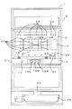
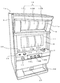
図1は本発明にかかる遊技機の一実施形態であるスロットマシンの外観を示す正面図である。この実施形態におけるスロットマシン1は、例えば図1に示すように構成されている。即ち、図1に示すように、スロットマシン1では、筐体3の前面が前面パネル5により開閉自在に閉塞され、この前面パネル5のほぼ中央高さの位置に操作板7が配設されると共に、この操作板7の上方に正面板9が配設されている。
FIG. 1 is a front view showing an appearance of a slot machine which is an embodiment of a gaming machine according to the present invention. The
そして、この正面板9には横長矩形のリール窓11が設けられ、このリール窓11の右横には、遊技者に当選又は入賞などを告知する演出用画面を表示するための液晶ディスプレイ13が配設されている。また、リール窓11の内側には左・中・右の回転リール12L,12M,12Rを備えたリールユニット14が配置され、リール窓11からは、回転リール12L,12M,12Rの図柄が上段・中段・下段の各々3個ずつ覗くように設定されている。更に、この操作板7には、内部に貯留されているクレジットメダルの枚数を減じてメダル投入に代えるためのベットスイッチ15、各回転リールの回転を開始させるためのスタートスイッチ17、左・中・右回転リール12L,12M,12Rの回転をそれぞれ停止させるための左・中・右ストップスイッチ19L,19M,19R、メダル投入口21、およびクレジットメダルを払い出すための精算スイッチ23が設けられている。
The
また、正面板9には入賞ラインが描かれると共に、入賞ライン中の有効ラインを表示する有効表示ランプ31、遊技者に当選又は入賞などを告知するための演出用ランプ33、クレジットメダルの枚数を表示するメダル枚数表示器35が配設され、操作板7の下方には、メダルの払出口37や、この払出口37から払い出されるメダルを受けるメダル受け39が設けられている。また、各回転リール12L,12M,12Rには、内側から図柄を照明するための例えばLEDからなる左・中・右のリール光源25L,25M,25R(図15)が内蔵されている。また、筐体3内部のリールユニット14の下方には、メダルを払出口37に排出するためのホッパーユニット27(図15)が配設されている。
In addition, a winning line is drawn on the
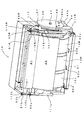
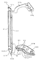
次に、リールユニット14の構成について説明する。図2はリールユニット14の全体斜視図、図3はドットユニットの斜視図、図4はシャッタユニットの斜視図、図5はモータユニットの斜視図である。また、図6は図2において駆動ギア45を取り外した状態の部分斜視図、図7は図6において支持壁111Rなどを取り外した状態の部分斜視図、図8は図2において左側の支持壁111Lを取り外した状態を左斜め後ろから見た部分斜視図である。
Next, the configuration of the
図2に示すように、このリールユニット14は、各回転リール12L,12M,12Rの前方(この実施形態では正面の上方)に設定された前方位置に配置可能なドット表示部41と、各回転リール12L,12M,12Rの前方(この実施形態では正面)に設定された前方位置に配置可能なシャッタ43とを備えている。ドット表示部41とシャッタ43とは、各前方位置と、各前方位置から後方に退避した各退避位置との間で、それぞれ移動可能に支持されている。リールユニット14の右側面には、駆動モータ44と、駆動モータ44のモータ軸44aに固定されたモータギア44bに噛み合わされた駆動ギア45とが配設されている。この駆動ギア45は、リールユニット14のほぼ中央に水平に配設された回転軸47に回動自在に取り付けられ、その主面の回転軸47から所定寸法だけ離れた位置には駆動軸体49が突設されている。そして、駆動モータ44が駆動されると駆動ギア45が回転し、それに伴って駆動軸体49が回転し、この駆動軸体49の回転がドット表示部41およびシャッタ43に伝達されて、これらが移動する。この伝達機構は、後に詳述する。
As shown in FIG. 2, the
ドット表示部41は、ドットマトリクス構成の多数のLEDが配置されたほぼ矩形形状の板状体で、図3に示すように、板状の保持フレーム51に保持されている。なお、ドット表示部41はLEDに限られず、LCDやELなどの発光表示体を用いるようにしてもよい。この保持フレーム51は、左右の両端部が前方に折り曲げられて形成された折り曲げ部51L,51Rを備えている。この左右の折り曲げ部51L,51Rには、それぞれ上下の両端部に外方に向けて一対のガイド軸体が突設されている。すなわち、左折り曲げ部51Lには、上端部に上側ガイド軸体53Lが、下端部に下側ガイド軸体55L(図8)が、それぞれ突設されている。また、右折り曲げ部51Rには、上端部に上側ガイド軸体53Rが、下端部に下側ガイド軸体55Rが、それぞれ突設されている。
The
この左右の下側ガイド軸体55L,55Rには、それぞれ左右のドットフレーム57L,57Rの一方端部が回動自在に軸支されている。この左右のドットフレーム57L,57Rは、それぞれ他方端部に透設された貫通孔59L,59Rにおいて、駆動ギア45の回転軸47に回動自在に軸支されている。左右のドットフレーム57L,57Rにより、左右の下側ガイド軸体55L,55Rを介して、ドット表示部41における下側ガイド軸体55L,55Rの軸中心が、回転軸47の周りに回動自在に支持されている。
One end portions of the left and right dot frames 57L and 57R are rotatably supported on the left and right lower guide shaft bodies 55L and 55R, respectively. The left and right dot frames 57L and 57R are pivotally supported on the
また、右ドットフレーム57Rには、ほぼ中央部に設けられた支持軸61に一端が回動自在に軸支されたドットカム63が取り付けられている。このドットカム63は、支持軸61側の一端から直線状に延びるとともに、この直線から円弧状に折れ曲がって形成されており、この直線部分から円弧部分に亘って駆動ガイド孔65が透設されている。この駆動ガイド孔65は、支持軸61を通る直線上に形成された短い直線部65aおよびこの直線部65aから折れ曲がって円弧状に形成された円弧部65bとを有する。この駆動ガイド孔65には駆動ギア45に突設された駆動軸体49が嵌挿している。また、ドットカム63上の支持軸61と直線部65aとの間には、ガイド軸体67が突設されている。
The
なお、右ドットフレーム57Rは、ドットカム63を挟む位置に、それぞれ縁が折り曲げられて形成された規制部69を備えており、これらの規制部69がドットカム63に当接することで、支持軸61周りのドットカム63の回動範囲を規制している。このように、この実施形態では、回転リール12L,12M,12Rが本発明の「図柄表示手段」に相当し、左右のドットフレーム57L,57Rが本発明の「第1フレーム」に相当し、支持軸61が本発明の「第1支持軸」に相当し、駆動ガイド孔65が本発明の「第1駆動ガイド孔」に相当し、ドットカム63が本発明の「第1カム」および「第1連結手段」に相当する。
The
シャッタ43は、図4に示すように、円柱側面の一部を切り出したような湾曲した板状体で、前方位置において各回転リール12L,12M,12R上の図柄を遮蔽するものである。この板状体の湾曲の曲率半径は、回転リール12L,12M,12Rの半径より多少大きくなっている。このシャッタ43は、その上端部が保持フレーム71に固定され、左右の両端部が後方に折り曲げられて形成された折り曲げ部43L,43Rを備えている。この左右の折り曲げ部43L,43Rには、それぞれ左右のシャッタフレーム73L,73Rの一方端部が固定されている。この左シャッタフレーム73Lは、ほぼL字形状で、他方端部に貫通孔75Lが透設されている。また、右シャッタフレーム73Rは、ほぼ中央で屈曲した「く」の字形状で、その屈曲部分に貫通孔75Rが透設されている。そして、左右のシャッタフレーム73L,73Rは、それぞれ貫通孔75L,75Rにおいて駆動ギア45の回転軸47に回動自在に軸支されており、この左右のシャッタフレーム73L,73Rによって、シャッタ43が回転軸47の周りに回動自在に支持されている。
As shown in FIG. 4, the
また、右シャッタフレーム73Rの他方端部には、貫通孔75Rから所定寸法離れた位置に支持軸77が設けられている。この支持軸77には、シャッタカム79の一端が回動自在に軸支されている。このシャッタカム79は、支持軸77側の一端から直線状に延びるとともに、この直線の途中から円弧状に折れ曲がってほぼT字形状に形成されている。このシャッタカム79には、駆動ギア45に突設された駆動軸体49が嵌挿する駆動ガイド孔81が透設されている。この駆動ガイド孔81は、支持軸77を通る直線上に形成された短い直線部81aおよびこの直線部81aから折れ曲がって円弧状に形成された円弧部81bを有する。このシャッタカム79の駆動ガイド孔81の円弧部81bは、ドットカム63の駆動ガイド孔65の円弧部65bと同一曲率で形成されている。また、シャッタカム79上の直線部81aに対して支持軸77と反対側には、ガイド軸体83が突設されている。
A
なお、右シャッタフレーム73Rは、シャッタカム79を挟む位置に、それぞれ縁が折り曲げられて形成された規制部85を備えており、これらの規制部85がシャッタカム79に当接することで、支持軸77周りのシャッタカム79の回動範囲を規制している。このように、この実施形態では、左右のシャッタフレーム73L,73Rが本発明の「第2フレーム」に相当し、支持軸77が本発明の「第2支持軸」に相当し、駆動ガイド孔81が本発明の「第2駆動ガイド孔」に相当し、シャッタカム79が本発明の「第2カム」および「第2連結手段」に相当する。
The right shutter frame 73R includes restricting portions 85 formed by bending edges at positions sandwiching the
図2に示すように、リールユニット14のユニットベース91には、各部を支持するための支持板93a,93b,93c,93dがそれぞれ立設されている。図5に示すように、駆動モータ44は、支持板93aに固定されており、駆動モータ44のモータ軸44aにはモータギア44bが固定され、このモータギア44bが駆動ギア45と噛み合わされている。駆動ギア45はモータギア44bより径が大きく構成されており、これによって減速機構を構成している。駆動ギア45の主面の回転軸47から所定寸法離れた円周上には複数の検出片95が並んで立設される一方、支持板93aの対応する位置には2個のフォトインタラプタ96,97が配設されており、これらのフォトインタラプタ96,97および検出片95により、駆動ギア45の回転位置を検出するエンコーダ99が構成されている。駆動モータ44は、本実施形態では例えばステッピングモータを用いている。なお、駆動モータ44はステッピングモータに限られず、DCモータなどの正転および反転が可能なモータであればよい。
As shown in FIG. 2, support plates 93 a, 93 b, 93 c, and 93 d are provided on the
図2に示すように、リールユニット14のユニットベース91の左右両端には、それぞれ左右の支持壁111L,111Rが立設されている。左支持壁111Lには、上側ガイド軸体53Lが嵌挿する移動ガイド孔113Lと、下側ガイド軸体55Lが嵌挿する移動ガイド孔115Lとが、それぞれ透設されている。また、図6に示すように、右支持壁111Rには、上側ガイド軸体53Rが嵌挿する移動ガイド孔113Rと、下側ガイド軸体55Rが嵌挿する移動ガイド孔115Rと、ガイド軸体67が嵌挿する移動ガイド孔117と、ガイド軸体83が嵌挿する移動ガイド孔119と、駆動軸体49が貫通するための貫通孔121とが、それぞれ透設されている。
As shown in FIG. 2, left and
移動ガイド孔113L,113Rは、互いに対向する位置に水平に透設されており、嵌挿している上側ガイド軸体53L,53Rを支持するとともに、その前後方向の移動を水平方向に案内する。移動ガイド孔115L,115Rは、互いに対向する位置に回転軸47を中心とする円弧状に透設されており、嵌挿している下側ガイド軸体55L,55Rを支持するとともに、その前後方向の移動を円弧に沿って案内する。このように、移動ガイド孔113L,113Rおよび115L,115Rが、それぞれガイド軸体53L,53Rおよび55L,55Rの移動を案内している。これによって、移動ガイド孔113L,113Rおよび115L,115Rの後端側に各ガイド軸体53L,53Rおよび55L,55Rが位置する(すなわちドット表示部41が退避位置にある)ときは、ドット表示部41の表面がほぼ上方を向いて、回転リール12L,12M,12Rの上方の隙間にドット表示部41が収容されるようになっている。そして、ドット表示部41が退避位置から前方位置に向けて移動するにしたがってドット表示部41の表面が徐々に下方を向き、移動ガイド孔113L,113Rおよび115L,115Rの前端側に各ガイド軸体53L,53Rおよび55L,55Rが位置する(すなわちドット表示部41が前方位置にある)と、ドット表示部41の表面がほぼ正面を向いて遊技者にとって見易い状態になる。
The movement guide holes 113L and 113R are horizontally provided at positions facing each other, support the inserted upper guide shaft bodies 53L and 53R, and guide the movement in the front-rear direction in the horizontal direction. The movement guide holes 115L and 115R are formed in a circular arc shape with the
また、移動ガイド孔117は、ガイド軸体67が嵌挿することでドットカム63の移動を案内するもので、回転軸47を中心とする円弧状に透設された後端側の円弧部117a(図10)と、ドットカム63の支持軸61を中心とする円弧状に透設された前端側の円弧部117b(図10)とからなる。また、移動ガイド孔119は、ガイド軸体83が嵌挿することでシャッタカム79の移動を案内するもので、回転軸47を中心とする円弧状に透設された前端側の円弧部119a(図14)と、シャッタカム79の支持軸77を中心とする円弧状に透設された後端側の円弧部119b(図14)とからなる。貫通孔121は、回転軸47を中心とする円弧状に、駆動軸体49の回動範囲に亘って透設されている。このように、この実施形態では、ガイド軸体67が本発明の「第1ガイド軸体」に相当し、移動ガイド孔117が本発明の「第1移動ガイド孔」に相当し、移動ガイド孔117の円弧部117aが本発明の「第1連結用円弧部」に相当し、移動ガイド孔117の円弧部117bが本発明の「第1解除用円弧部」に相当する。また、ガイド軸体83が本発明の「第2ガイド軸体」に相当し、移動ガイド孔119が本発明の「第2移動ガイド孔」に相当し、移動ガイド孔119の円弧部119aが本発明の「第2連結用円弧部」に相当し、移動ガイド孔119の円弧部119bが本発明の「第2解除用円弧部」に相当する。
The
図8に示すように、ユニットベース91に立設された支持板93dには、フォトインタラプタ123,125,127,129が取り付けられたセンサ載置板131が固定されている。フォトインタラプタ123,125は、左ドットフレーム57Lの一部が折り曲げられて形成された検出片57aを検出することにより、左ドットフレーム57Lの回転位置、すなわちドット表示部41の位置を検出するもので、フォトインタラプタ123がドット表示部41の前方位置への到達を検出し、フォトインタラプタ125がドット表示部41の退避位置への到達を検出する。また、フォトインタラプタ127,129は、左シャッタフレーム73Lの一部が折り曲げられて形成された検出片73aを検出することにより、左シャッタフレーム73Lの回転位置、すなわちシャッタ43の位置を検出するもので、フォトインタラプタ127がシャッタ43の前方位置への到達を検出し、フォトインタラプタ129がシャッタ43の退避位置への到達を検出する。
As shown in FIG. 8, a sensor mounting plate 131 to which
図9〜図14はドット表示部41およびシャッタ43の移動を説明するためのリールユニット14の右側面図である。図9はドット表示部41およびシャッタ43の双方が退避位置にある状態、図10はドット表示部41が前方位置に到達した状態、図11は駆動軸体49とドットカム63との連結が解除された状態、図12は駆動軸体49の連結が切換途中の状態、図13は駆動軸体49とシャッタカム79とが連結された状態、図14はシャッタ43が前方位置に到達した状態を、それぞれ示している。
9 to 14 are right side views of the
なお、図9〜図14では、説明の便宜上、以下のように図示している。(1)各構成要素を実線で示す。(2)右ドットフレーム57Rを模式的にほぼL字形状に示す。(3)シャッタ43を模式的に扇形状に示す。(4)右シャッタフレーム73R、移動ガイド孔115Rおよび貫通孔121の図示を省略する。(5)各部の円運動の軌跡および中心を一点鎖線で示す。
9 to 14 are illustrated as follows for convenience of explanation. (1) Each component is indicated by a solid line. (2) The
まず、退避位置にあるドット表示部41およびシャッタ43の前方位置への前進移動について説明する。図9に示すように、ドット表示部41およびシャッタ43の双方が退避位置にあるときには、駆動軸体49は、ドットカム63の駆動ガイド孔65の直線部65aの内部に嵌挿するとともに、シャッタカム79の駆動ガイド孔81の円弧部81bの後端に嵌挿している。また、ドットカム63の右ドットフレーム57Rに対する支持軸61を中心とする回転位置は、ドットカム63の支持軸61とガイド軸体67と駆動ガイド孔65の直線部65aとを結ぶ直線上に回転軸47の軸中心47aが配置されるように設定されている。図9に示すようにドット表示部41およびシャッタ43の双方が退避位置にある状態が本発明の「初期状態」に相当する。
First, the forward movement of the
図9の状態から、駆動モータ44の回転開始により駆動ギア45が反時計回り方向に回転を始めると、回転する駆動軸体49がドットカム63の駆動ガイド孔65の直線部65aを押す。このとき、ドットカム63の移動方向は、ガイド軸体67が嵌挿する移動ガイド孔117によって案内されるが、上述したように、移動ガイド孔117のうちで、後端から図10に示すガイド軸体67の嵌挿位置までの円弧部117a(図10)は、回転軸47を中心とする円弧状に支持壁111Rに透設されている。したがって、図10に示すように、ガイド軸体67の移動軌跡131と、支持軸61を介して移動する右ドットフレーム57Rの移動軌跡133とは、駆動軸体49の移動軌跡135と同様に、回転軸47を中心とする円弧状となる。これによって、ドットカム63の右ドットフレーム57Rに対する支持軸61を中心とする回転位置は図9の状態を保ったまま、ドット表示部41が前方に向けて移動し、図10においてドット表示部41は前方位置に到達する。また、図10に示すように、上側ガイド軸体53Rの移動軌跡137は、水平となり、下側ガイド軸体55Rの移動軌跡139は、回転軸47を中心とする円弧状となる。これによって、図9では上方を向いているドット表示部41が徐々に下方を向いて、図10の前方位置では、ほぼ正面を向くようになっている。
When the drive gear 45 starts to rotate counterclockwise as the
図10に示す位置から駆動ギア45がさらに反時計回り方向に回転すると、駆動軸体49がドットカム63の駆動ガイド孔65の直線部65aをさらに押す。このとき、ドットカム63の移動方向は、やはりガイド軸体67が嵌挿する移動ガイド孔117によって案内されるが、上述したように、移動ガイド孔117のうちで、図10に示すガイド軸体67の嵌挿位置から前端までの円弧部117bは、支持軸61を中心とする円弧状に支持壁111Rに透設されている。したがって、図11に示すように、駆動軸体49の移動軌跡135が回転軸47を中心とする円弧状となるのに対して、ガイド軸体67の移動軌跡131は、支持軸61の軸中心61aを中心とする円弧状となる。これによって、ドットカム63は右ドットフレーム57Rに対して支持軸61の軸中心61aを中心として時計回り方向に回転し、図11に示すように、ドットカム63の駆動ガイド孔65の円弧部65bは、回転軸47を中心とする円弧に一致することとなる。このドットカム63の回転により、駆動軸体49の駆動ガイド孔65における嵌挿位置が、直線部65aのほぼ中央から直線部65aの終端、すなわち円弧部65bの始端に移動する。図11に示す位置から、駆動ギア45がさらに反時計回り方向に回転しても、駆動軸体49は、ドットカム63の駆動ガイド孔65の円弧部65bの内部を移動するだけであるので、駆動モータ44の駆動力は右ドットフレーム57Rに伝達されない。すなわち、ドットカム63の右ドットフレーム57Rに対する支持軸61を中心とする回転によって、駆動モータ44と右ドットフレーム57Rとの間が連結状態から連結解除状態に切り換えられている。
When the drive gear 45 further rotates counterclockwise from the position shown in FIG. 10, the
なお、図9の状態から図11の状態までは、駆動軸体49が嵌挿するシャッタカム79の駆動ガイド孔81の円弧部81bは、回転軸47を中心とする円弧に一致している。このため、駆動ギア45が反時計回り方向に回転しても、駆動軸体49は、シャッタカム79の駆動ガイド孔81の円弧部81bの内部を移動するだけであるので、駆動モータ44の駆動力は右シャッタフレーム73Rに伝達されない。すなわち、駆動モータ44と右シャッタフレーム73Rとの間は連結解除状態になっている。
From the state of FIG. 9 to the state of FIG. 11, the arc portion 81 b of the
図11の状態から、駆動ギア45がさらに反時計回り方向に回転すると、駆動軸体49は、シャッタカム79の駆動ガイド孔81の円弧部81bの内部を移動し、円弧部81bの終端に到達して図12に示す状態となる。すなわち、図11の状態から図12の状態までの間は、ドットカム63の駆動ガイド孔65の円弧部65bおよびシャッタカム79の駆動ガイド孔81の円弧部81bの双方が回転軸47を中心とする円弧に一致しており、双方の円弧部65b,81bの曲率が等しいため、駆動軸体49から見ると両者が連通状態になっている。これによって、図11の状態から図12の状態までの間は、駆動モータ44と右ドットフレーム57Rとの間、駆動モータ44と右シャッタフレーム73Rとの間が、いずれも連結解除状態になっている。このように、この実施形態では、図11の状態から図12の状態までの間が本発明の「移行区間」に相当する。
When the drive gear 45 further rotates counterclockwise from the state of FIG. 11, the
図12の状態から、駆動ギア45がさらに反時計回り方向に回転すると、駆動軸体49は、シャッタカム79の駆動ガイド孔81の円弧部81bの終端を押し始める。このとき、シャッタカム79の移動方向は、ガイド軸体83が嵌挿する移動ガイド孔119によって案内される。この移動ガイド孔119のうちで、後端から図13に示すガイド軸体83の嵌挿位置までの円弧部119b(図14)は、支持軸77を中心とする円弧状に支持壁111Rに透設されている。したがって、図13に示すように、駆動軸体49の移動軌跡135が回転軸47の軸中心47aを中心とする円弧状となるのに対して、ガイド軸体83の移動軌跡141は、支持軸77の軸中心77aを中心とする円弧状となる。このため、図13に示すように、シャッタカム79は右シャッタフレーム73Rに対して支持軸77を中心として反時計回り方向に回転する。これによって、シャッタカム79の駆動ガイド孔81の円弧部81bは、回転軸47を中心とする円周上から外れる。このとき、シャッタカム79が右シャッタフレーム73Rに対して回転するだけであり、右シャッタフレーム73Rは移動しない。また、駆動軸体49の駆動ガイド孔81における嵌挿位置が、円弧部81bの終端から直線部81aの内部に移動する。すなわち、シャッタカム79の右シャッタフレーム73Rに対する支持軸77を中心とする回転によって、駆動モータ44と右シャッタフレーム73Rとの間が連結解除状態から連結状態に切り換えられている。
When the drive gear 45 further rotates counterclockwise from the state of FIG. 12, the
図13の状態から、駆動ギア45がさらに反時計回り方向に回転すると、駆動軸体49がシャッタカム79の駆動ガイド孔81の直線部81aを押す。このとき、シャッタカム79の移動方向は、ガイド軸体83が嵌挿する移動ガイド孔119によって案内される。ここで、移動ガイド孔119のうちで、図13に示すガイド軸体83の嵌挿位置から前端までの円弧部119a(図14)は、回転軸47を中心とする円弧状に支持壁111Rに透設されている。したがって、図14に示すように、ガイド軸体83の移動軌跡141は、駆動軸体49の移動軌跡135と同様に、回転軸47を中心とする円弧状となる。このため、支持軸77を中心とするシャッタカム79の右シャッタフレーム73Rに対する回転位置は図13の状態を保ったまま、右シャッタフレーム73Rが反時計回り方向に回転し、これによってシャッタ43が前方位置に向けて移動する。そして、図14において、シャッタ43は前方位置に到達し、駆動モータ44が停止すると、シャッタ43が前方位置に配置された図14の状態が維持される。
When the drive gear 45 further rotates counterclockwise from the state shown in FIG. 13, the
なお、図11〜図14では、ドットカム63には、自重により右ドットフレーム57Rに対して支持軸61を中心とする反時計回り方向の力が作用するが、駆動ガイド孔65に嵌挿する駆動軸体49によって支えられるため、駆動ガイド孔65の円弧部65bが回転軸47の軸中心47aを中心とする円弧に一致する状態が維持される。
In FIGS. 11 to 14, a force in the counterclockwise direction around the
次に、ドット表示部41およびシャッタ43の前方位置から退避位置への後退移動について簡単に説明する。ドット表示部41およびシャッタ43の後退移動では、図14の状態から各図の状態を上記と逆に経て、図9の状態に移行することとなる。
Next, the backward movement of the
図14の状態から、駆動モータ44が反転して駆動ギア45が時計回り方向に回転すると、駆動軸体49がシャッタカム79の駆動ガイド孔81の直線部81aを押す。このとき、シャッタカム79の移動方向は、ガイド軸体83が嵌挿する移動ガイド孔119によって案内されるが、この部分の移動ガイド孔119の円弧部119aは、回転軸47を中心とする円弧状に透設されているので、ガイド軸体83は、駆動軸体49と同様に回転軸47の軸中心47aを中心とする円弧状に移動する。これによって、右シャッタフレーム73Rは回転軸47を中心として時計回り方向に回転し、シャッタ43が前方位置から、図13に示す退避位置まで後退移動する。
From the state of FIG. 14, when the
図13の状態から駆動ギア45がさらに時計回り方向に回転すると、駆動軸体49がシャッタカム79の駆動ガイド孔81の直線部81aをさらに押す。このとき、シャッタカム79の移動方向は、ガイド軸体83が嵌挿する移動ガイド孔119によって案内されるが、図13に示すガイド軸体83の嵌挿位置から後端までの移動ガイド孔119の円弧部119bは、支持軸77を中心とする円弧状に透設されている。したがって、駆動軸体49が回転軸47の軸中心47aを中心とする円弧状に移動するのに対して、ガイド軸体83は支持軸77の軸中心77aを中心とする円弧状に移動する。このため、シャッタカム79は右シャッタフレーム73Rに対して支持軸77を中心として時計回り方向に回転し、右シャッタフレーム73Rは移動しない。
When the drive gear 45 further rotates in the clockwise direction from the state of FIG. 13, the
シャッタカム79の回転はガイド軸体83が移動ガイド孔119の円弧部119bの後端に到達すると停止して、図12に示すように、シャッタカム79の駆動ガイド孔81の円弧部81bは、回転軸47の軸中心47aを中心とする円弧に一致することとなる。また、駆動軸体49の駆動ガイド孔81における嵌挿位置が、直線部81aの終端であって円弧部81bの始端に移動する。これ以降、駆動ギア45がさらに時計回り方向に回転しても、駆動軸体49は、シャッタカム79の駆動ガイド孔81の円弧部81bの内部を移動するだけであるので、駆動モータ44の駆動力は右シャッタフレーム73Rに伝達されない。すなわち、シャッタカム79の支持軸77を中心とする回転によって、駆動モータ44と右シャッタフレーム73Rとの間が連結状態から連結解除状態に切り換えられている。
The rotation of the
なお、図14の状態から図12の状態までの間は、ドットカム63の駆動ガイド孔65に嵌挿している駆動軸体49は、駆動ガイド孔65の円弧部65bの内部を移動するだけであるので、駆動モータ44の駆動力は右ドットフレーム57Rに伝達されない。
14 to 12, the
図12の状態から駆動ギア45がさらに時計回り方向に回転すると、駆動軸体49がドットカム63の駆動ガイド孔65の円弧部65bの内部を移動し、円弧部65bの終端に到達して図11の状態になる。すなわち、上述したように、図12の状態から図11の状態までの間は、駆動モータ44と右ドットフレーム57Rとの間、駆動モータ44と右シャッタフレーム73Rとの間が、いずれも連結解除状態になっている。このように、この実施形態では、図12の状態から図11の状態までの間が本発明の「移行区間」に相当する。
When the drive gear 45 further rotates in the clockwise direction from the state of FIG. 12, the
図11の状態から駆動ギア45がさらに時計回り方向に回転すると、駆動軸体49がドットカム63の駆動ガイド孔65の円弧部65bの終端を押し始める。このとき、ドットカム63の移動方向は、ガイド軸体67が嵌挿する移動ガイド孔117によって案内されるが、この部分の移動ガイド孔117の円弧部117b(図10)は、支持軸61の軸中心61aを中心とする円弧状に透設されている。このため、ドットカム63は右ドットフレーム57Rに対して支持軸61を中心として反時計回り方向に回転し、ドットカム63の駆動ガイド孔65の円弧部65bは、回転軸47を中心とする円周上から外れる。また、駆動軸体49の駆動ガイド孔65における嵌挿位置が、円弧部65bの終端から外れて直線部65aの内部に移動し、図10に示す状態となる。
When the drive gear 45 further rotates in the clockwise direction from the state of FIG. 11, the
図10の状態から駆動ギア45がさらに時計回り方向に回転すると、駆動軸体49がドットカム63の駆動ガイド孔65の直線部65aを押す。このとき、ドットカム63の移動方向は、ガイド軸体67が嵌挿する移動ガイド孔117によって案内されるが、移動ガイド孔117の図10に示すガイド軸体67の嵌挿位置から後端までの円弧部117aは、回転軸47の軸中心47aを中心とする円弧状に透設されている。したがって、図11の位置から開始されたドットカム63の右ドットフレーム57Rに対する回転は図10の位置で終了し、図10の位置から、ドットカム63は、右ドットフレーム57Rとともに回転軸47を中心とする時計回り方向の回転を開始する。これによって、ドット表示部41が退避位置に向けて移動を開始し、図9に示す退避位置に到達する。
When the drive gear 45 further rotates in the clockwise direction from the state of FIG. 10, the
このように、この実施形態では、ドット表示部41が本発明の「第1演出手段」に相当し、図9に示すドット表示部41の退避位置が本発明の「第1退避位置」に相当し、図10に示すドット表示部41の前方位置が本発明の「第1前方位置」に相当する。また、シャッタ43が本発明の「第2演出手段」に相当し、図9に示すシャッタ43の退避位置が本発明の「第2退避位置」に相当し、図14に示すシャッタ43の前方位置が本発明の「第2前方位置」に相当する。
Thus, in this embodiment, the
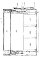
図15はスロットマシン1の電気的構成を示すブロック図である。また、図16〜図18はリールユニット14の正面図で、図16はドット表示部41およびシャッタ43の双方が退避位置にある状態、図17はドット表示部41が前方位置に到達した状態、図18はシャッタ43が前方位置に到達した状態を、それぞれ示している。
FIG. 15 is a block diagram showing an electrical configuration of the
図15において、投入センサ201は、メダル投入口21に設けられ、投入されたメダルを検知するものである。メモリ203には遊技機用プログラムが格納されており、CPU205は、この遊技機用プログラムにしたがって動作すると、遊技制御手段205aおよび演出制御手段205bとして機能する。遊技には、一般的な遊技である通常遊技と、遊技者にとって通常遊技よりも有利な遊技である特別遊技(ボーナスゲーム)とがあり、遊技制御手段205aはこれらの遊技を制御する。
In FIG. 15, the
通常遊技の概要について説明する。このスロットマシン1では、投入センサ201によりメダル投入口21からのメダル投入が検出されるか、またはベットスイッチ15の操作によりクレジットメダルの投入指示があると、ゲームが開始される。そして、ゲーム開始後にスタートスイッチ17を操作すると、まず、当選か否かの抽選が行われ、ほぼ同時に、3個すべての回転リール12L,12M,12Rの回転が開始する。その後に、3個のストップスイッチ19L,19M,19Rのうちの1個を操作すると、当該ストップスイッチ19L,19M,19Rに対応した回転リール12L,12M,12Rの回転が停止する。そして、3個すべてのストップスイッチ19L,19M,19Rを操作し終えると、3個すべての回転リール12L,12M,12Rの回転が停止する。このとき、所定の図柄が所定の位置に停止すると入賞になり、ホッパーユニット27により遊技者に対して所定枚数のメダルが払い出されるか、又は遊技者に対してリプレイなどの所定の利益が付与される。なお、メダルの払い出しに代えて、クレジットメダルとして内部に貯留されることもある。
An outline of the normal game will be described. In this
抽選結果には、特定導入遊技当選(ビッグボーナス(BB)当選)と、特定遊技当選(レギュラーボーナス(RB)当選)と、小役当選と、再遊技当選(Replay当選)と、ハズレとがある。また、入賞には、特定導入遊技(BBゲーム)への移行に係る特定導入遊技入賞(BB入賞)と、特定遊技(RBゲーム)への移行に係る特定遊技入賞(RB入賞)と、所定枚数のメダルの払い出しに係る小役入賞と、再遊技(Replay)の実行に係る再遊技入賞(Replay入賞)とがある。 The lottery results include specific introduction game wins (big bonus (BB) wins), specific game wins (regular bonus (RB) wins), small role wins, replay wins (Replay wins), and loses. . In addition, the prize includes a specific introduction game prize (BB prize) related to the transition to the specific introduction game (BB game), a specific game prize (RB prize) related to the transition to the specific game (RB game), and a predetermined number of games. Small prize winning related to the payout of the medal and replay winning related to the execution of replay (Replay).
上記RBゲームとは、特定入賞遊技(JACゲーム)を複数回行い得ることにより、通常遊技よりも当選確率が高い遊技をいい、また、BBゲームとは、RBゲームの導入確率が高い遊技をいい、これらが本発明の「特別遊技」に相当する。そして、所定の図柄(例えば「赤7」または「青7」)が入賞ライン上に3個揃うと、BB入賞となり、払い出しがある場合にはメダルが払い出されて、通常遊技からBBゲームに移行する。また、所定の図柄(例えば「スイカ」)が入賞ライン上に3個揃うと、小役入賞となり、所定枚数のメダルが払い出される。また、例えば、「Replay」の図柄が入賞ライン上に3個揃うと、Replay入賞となり、新たなメダルを投入することなく、前回の遊技と同じ条件で再度遊技を行うことができる。
The RB game refers to a game having a higher winning probability than a normal game because a specific winning game (JAC game) can be performed a plurality of times, and the BB game refers to a game having a high probability of introducing an RB game. These correspond to the “special game” of the present invention. Then, when three predetermined symbols (for example, “
なお、抽選結果がBB当選になると、BB当選に基づいた図柄の停止制御が行われるが、このとき、BB入賞が引き当てられないと、このBB当選は、BB入賞が引き当てられるまで持ち越されることとなっている。RB当選についても同様である。BB当選またはRB当選が持ち越された状態をそれぞれ「BB内部当り」、「RB内部当り」と称する。一方、小役当選は、抽選結果が小役当選となった遊技で小役入賞を引き当てられないと、次回の遊技には持ち越されないこととなっている。Replay当選についても同様である。 When the lottery result is BB winning, the symbol stop control based on the BB winning is performed. At this time, if the BB winning is not made, the BB winning is carried over until the BB winning is made. It has become. The same applies to RB winning. The states where the BB winning or the RB winning is carried over are referred to as “per BB internal” and “per RB internal”, respectively. On the other hand, the small role winning is not carried over to the next game unless a small role winning is awarded in a game whose lottery result is a small role winning. The same applies to Replay winning.
演出制御手段205bは、遊技に関連する演出として、例えば抽選結果や入賞の有無などを遊技者に告知するために、液晶ディスプレイ13や演出用ランプ33、各リール光源25L,25M,25R、ドット表示部41などの動作を制御するもので、例えば各々の演出パターンに応じた動画を液晶ディスプレイ13に表示させたり、演出用ランプ33を一斉にあるいは個別に点滅させたり、各リール光源25L,25M,25Rを点滅させたり、ドット表示部41に絵柄や文字などを表示させる。
The effect control means 205b provides, for example, a lottery result or a prize presence / absence as an effect related to the game, such as a liquid crystal display 13, an
また、演出制御手段205bは、遊技に関連する演出として、例えば各々の演出パターンに応じて駆動モータ44を動作させてドット表示部41およびシャッタ43を移動させる。例えば、通常遊技中には、図16に示すように、ドット表示部41およびシャッタ43の双方を退避位置に退避させておく。
Further, the
そして、例えば通常遊技からBBゲームまたはRBゲームに移行したときに、ドット表示部41を退避位置から前方位置に向けて前進移動させて、各LEDを一斉にあるいは個別に点滅させる演出を行う。この演出は、例えば各回転リール12L,12M,12Rの回転中にのみ行うようにしてもよい。ドット表示部41が前方位置にあると、図17に示すように、ドット表示部41がほぼ正面を向いているため、遊技者の見易い位置で効果的に演出を行うことが可能になる。
Then, for example, when a transition is made from a normal game to a BB game or an RB game, the
また、演出制御手段205bは、例えばドット表示部41が前方位置にある状態で、各回転リール12L,12M,12Rの停止中に、シャッタ43を退避位置から前方位置に向けて前進移動させて、各回転リール12L,12M,12Rの図柄を遮蔽する演出を行う。シャッタ43が前方位置にあると、図18に示すように、各回転リール12L,12M,12Rの上端からほぼ中央部までシャッタ43により遮蔽される。これによって、ドット表示部41の演出中に、リール窓11から覗く各回転リール12L,12M,12Rの上段および中段の図柄を遮蔽するなどの演出を行うことが可能になる。なお、演出制御手段205bは、各回転リール12L,12M,12Rの回転中にも、シャッタ43を前方位置に前進移動させてもよい。
In addition, the
ここで、演出制御手段205bは、フォトインタラプタ123,125からの検出信号に基づき、それぞれドット表示部41の前方位置および退避位置への到達を判定し、フォトインタラプタ127,129からの検出信号に基づき、それぞれシャッタ43の前方位置および退避位置への到達を判定する。また、演出制御手段205bは、フォトインタラプタ96,97からの検出信号に基づき、ドット表示部41およびシャッタ43の前方位置と退避位置との間における位置を判定する。
Here, the effect control means 205b determines the arrival of the
なお、演出制御手段205bによる演出は上記に限られない。例えば各LEDの点滅を行いながら、ドット表示部41を退避位置から前方位置に移動する途中で退避位置に戻すような演出を行ったり、例えばシャッタ43を退避位置と前方位置との間で往復移動させる演出を行ってもよい。また、例えばシャッタ43をスモークおよびハーフミラーなどの半透明の材質で形成しておき、シャッタ43が前方位置にある状態で、通常は各リール光源25L,25M,25Rを消灯しておくことで回転リール12L,12M,12Rの図柄を見にくくしていておき、所定のタイミングで各リール光源25L,25M,25Rを点灯させて、シャッタ43を通して図柄を遊技者に見易くするような演出を行うと、さらに遊技者の興趣を増すことができる。
The production by the production control means 205b is not limited to the above. For example, while performing blinking of each LED, an effect is provided such that the
以上説明したように、この実施形態によれば、回転リール12L,12M,12Rの前方位置と退避位置との間で移動可能なドット表示部41およびシャッタ43を備え、演出パターンに応じてこれらの移動を制御しているため、多様な演出を行うことができ、これによって十分な演出効果を得ることができ、遊技者の興趣を高めることができる。
As described above, according to this embodiment, the
また、この実施形態によれば、ドット表示部41を支持する右ドットフレーム57Rと駆動モータ44との間を連結状態としてドット表示部41を移動させ、連結状態を連結解除状態に切り換えた後、シャッタ43を支持する右シャッタフレーム73Rと駆動モータ44との間を連結解除状態から連結状態に切り換えて、シャッタ43を移動させるようにしているため、1つの駆動モータ44でドット表示部41およびシャッタ43を移動させることができ、これによって、駆動モータの増加による筐体3の大型化を未然に防止することができる。
Further, according to this embodiment, after the
また、この実施形態によれば、移動ガイド孔117によりドットカム63の移動を案内し、移動ガイド孔119によりシャッタカム79の移動を案内することにより、右ドットフレーム57Rと駆動モータ44との間および右シャッタフレーム73Rと駆動モータ44との間における連結状態と連結解除状態との切換えを、駆動モータ44による駆動軸体49の回転により自動的に行うようにしているため、連結切換専用の構成が不要とすることができ、これによって装置構成を簡素化することができる。
Further, according to this embodiment, the movement of the dot cam 63 is guided by the
また、この実施形態によれば、左右のドットフレーム57L,57Rによりドット表示部41を回転軸47周りに回転可能に支持し、左右のシャッタフレーム73L,73Rによりシャッタ43を回転軸47周りに回転可能に支持して、前方位置から退避位置までドット表示部41およびシャッタ43を回転リール12L,12M,12Rの周面に沿って回転移動させているため、退避位置において、ドット表示部41およびシャッタ43を回転リール12L,12M,12Rの上方の限られたスペースに配置することができる。これによって、ドット表示部41およびシャッタ43を退避位置に配置するスペースを確保するために筐体3が大型化するのを未然に防止することができる。
Further, according to this embodiment, the
なお、本発明は上記実施形態に限定されるものではなく、その趣旨を逸脱しない限りにおいて上述したもの以外に種々の変更を行うことが可能である。例えば、ドット表示部41およびシャッタ43が双方とも退避位置にある初期状態において、上記実施形態とは逆に、右シャッタフレーム73Rと駆動モータ44との間を連結状態にしておき、シャッタ43を前方位置に移動させた後、連結状態を切り換えてドット表示部41を前方位置に移動するようにしてもよい。この形態では、シャッタ43が本発明の「第1演出手段」に相当し、ドット表示部41が本発明の「第2演出手段」に相当する。ただし、ドット表示部41を先に前方位置に移動させる上記実施形態の方が、回転リール12L,12M,12Rの図柄を遮蔽しない状態でドット表示部41による演出ができるので、より高い演出効果が得られるため好ましい。
The present invention is not limited to the above embodiment, and various modifications other than those described above can be made without departing from the spirit of the present invention. For example, in the initial state where both the
また、上記実施形態では、リールユニット14の回転リール12L,12M,12Rをスタートスイッチ17の操作で回転を開始する入賞に関連する回転リールとしているが、本発明はこれに限られず、例えば図19に示すように入賞に関連しない演出用の回転リールとしてもよい。図19は変形形態のスロットマシン1aの外観を示す斜視図である。なお、図19では、図1と同一物には同一符号を付している。
In the above embodiment, the rotating
このスロットマシン1aは、図19に示すように、2組の回転リールを備えている。すなわち、正面板9の上方に設けられた横長矩形のリール窓11aの内側に上記リールユニット14の回転リール12L,12M,12Rが設けられ、正面板9のリール窓11の内側に回転リール22L,22M,22Rが設けられている。そして、下方の回転リール22L,22M,22Rは、スタートスイッチ17の操作で回転を開始する入賞に関連する回転リールであり、例えば遊技制御手段205a(図15)により回転が制御される。一方、上方のリールユニット14の回転リール12L,12M,12Rは、入賞に関連しない演出用の回転リールであり、例えば演出制御手段205b(図15)により演出パターンに応じて回転が制御される。このリールユニット14は上記実施形態と同一構成であり、演出パターンに応じて、回転リール12L,12M,12Rの前方位置へのドット表示部41およびシャッタ43の移動が制御される。この図19の形態でも、上記実施形態と同様の効果を得ることができる。
As shown in FIG. 19, the slot machine 1a includes two sets of rotating reels. That is, the
また、上記実施形態では、ドット表示部41を前方位置に移動させた後、連結状態を切り換えてシャッタ43を前方位置に移動させるようにしているが、本発明はこれに限られず、ドット表示部41およびシャッタ43のいずれかを択一的に移動可能に構成してもよい。すなわち、例えばドット表示部41およびシャッタ43の双方が退避位置にある初期状態においてのみ連結状態を切換可能に構成しておき、ドット表示部41の前方位置への前進移動および退避位置への後退移動と、シャッタ43の前方位置への前進移動および退避位置への後退移動とを択一的に行うようにしてもよい。
In the above embodiment, the
また、上記実施形態では、第2演出手段を1つのシャッタ43で構成しているが、本発明はこれに限られず、分割形成された2つのシャッタで第2演出手段を構成するようにしてもよい。例えば、シャッタ43と同様に回転リール12L,12M,12Rの上方の退避位置に設けられた上部シャッタと、回転リール12L,12M,12Rの下方の退避位置に設けられた下部シャッタとを備え、上部シャッタを上記実施形態のシャッタ43と同様に回転移動させるとともに、下部シャッタを下方の退避位置から上部シャッタと反対方向に回転移動させて前方位置に移動させるようにしてもよい。この形態によれば、上部シャッタおよび下部シャッタを互いに異なる動きとなるように移動を制御することにより、さらに多様な演出を行うことができ、演出効果をさらに一層高めることができる。
Moreover, in the said embodiment, although the 2nd production | presentation means is comprised by the one
また、上記実施形態では、ドット表示部41およびシャッタ43を回転リール12L,12M,12Rの周面に沿って回転移動させているが、本発明はこれに限られず、例えば図20に示すようにドット表示部41およびシャッタ43を上下方向に昇降移動させるようにしてもよい。図20は別の変形形態のスロットマシンの筐体内部を示す右側面図である。このスロットマシンでは、図20(A)に示すようにドット表示部41およびシャッタ43の退避位置を回転リール12L,12M,12Rとリール窓11との隙間の上方に設定し、ドット表示部41およびシャッタ43を前後に並べて両者の下端を揃えた状態で配置しておく。そして、図20(B)に示すように、ドット表示部41およびシャッタ43を同時にドット表示部41の前方位置に降下移動させる。さらに、図20(C)に示すように、シャッタ43をドット表示部41の背後でさらにシャッタ43の前方位置に降下移動させる。また、退避位置への移動は、まずシャッタ43をドット表示部41の前方位置に上昇移動させた後、ドット表示部41およびシャッタ43を同時に退避位置に上昇移動させればよい。この形態によれば、ドット表示部41およびシャッタ43を直線的に昇降移動させるだけであるため、ドット表示部41およびシャッタ43の移動を案内するガイド部材の構成を簡素化することができる。
Moreover, in the said embodiment, although the
なお、図20とは逆に、ドット表示部41およびシャッタ43の退避位置を回転リール12L,12M,12Rとリール窓11との隙間の下方に設定し、ドット表示部41およびシャッタ43を前後に並べて両者の上端を揃えた状態で配置しておいて、両者をそれぞれ前方位置に上昇移動させるようにしてもよい。また、ドット表示部41およびシャッタ43の移動は、昇降移動に限られず、横方向に水平移動させるようにしてもよい。このように、ドット表示部41およびシャッタ43を直線的に往復移動させる形態にすると、それらの移動を案内するガイド部材の構成を簡素化することができる。ただし、横方向に水平移動させる形態では、リールユニット14の横にドット表示部41およびシャッタ43を退避させるスペースが必要になるので、筐体3の設置スペースの大型化を招くことになるため、上記実施形態のように回転移動させる形態や、図20のように昇降移動させる形態の方が好ましい。
Contrary to FIG. 20, the retracted positions of the
また、上記実施形態や上記図19では、ドット表示部41およびシャッタ43を回転リールの前方位置に移動させるようにしているが、本発明の「図柄表示手段」は回転リールに限られない。例えば、液晶ディスプレイやエレクトロルミネッセンスなどの演出用の図柄を表示する表示デバイスの前方位置にドット表示部41およびシャッタ43を移動させるようにしてもよい。
In the above embodiment and FIG. 19, the
1,1a…スロットマシン、12L,12M,12R…回転リール(図柄表示手段)、41…ドット表示部(第1演出手段、発光表示体)、43…シャッタ(第2演出手段)、44…駆動モータ(駆動動力源)、47…回転軸、49…駆動軸体、57L,57R…左右のドットフレーム(第1フレーム、第1支持手段)、61…支持軸(第1支持軸)、63…ドットカム(第1カム、第1連結手段)、65…駆動ガイド孔(第1駆動ガイド孔)、65b…円弧部(第1円弧部)、67…ガイド軸体(第1ガイド軸体)、73L,73R…左右のシャッタフレーム(第2フレーム、第2支持手段)、77…支持軸(第2支持軸)、79…シャッタカム(第2カム、第2連結手段)、81…駆動ガイド孔(第2駆動ガイド孔)、81b…円弧部(第2円弧部)、83…ガイド軸体(第2ガイド軸体)、111R…右支持壁(支持壁)、117…移動ガイド孔(第1移動ガイド孔)、117a…円弧部(第1連結用円弧部)、117b…円弧部(第1解除用円弧部)、119…移動ガイド孔(第2移動ガイド孔)、119a…円弧部(第2連結用円弧部)、119b…円弧部(第2解除用円弧部)、205…CPU、205b…演出制御手段(制御手段)
DESCRIPTION OF
Claims (2)
前記図柄表示手段の前方の第1前方位置と該第1前方位置から退避した第1退避位置との間で移動可能に設けられた第1演出手段と、
前記図柄表示手段の前方の第2前方位置と該第2前方位置から退避した第2退避位置との間で移動可能に設けられた第2演出手段と、
前記第1演出手段および前記第2演出手段を移動させる駆動手段と、
遊技状況に応じた所定の演出パターンで前記駆動手段を制御する制御手段と
を備え、
前記駆動手段が、
前記第1演出手段を前記第1前方位置と前記第1退避位置との間で移動可能に支持する第1支持手段と、
前記第2演出手段を前記第2前方位置と前記第2退避位置との間で移動可能に支持する第2支持手段と、
駆動動力源と、
前記駆動動力源の出力を前記両支持手段にそれぞれ伝達して前記両演出手段を移動させる伝達手段と
を備えたものであり、
前記駆動動力源が駆動モータであり、
前記伝達手段が、
前記駆動モータと前記第1支持手段との間を連結・連結解除状態に切換自在に連結する第1連結手段と、
前記駆動モータと前記第2支持手段との間を連結・連結解除状態に切換自在に連結する第2連結手段と
を備えたものであり、
前記第1演出手段が前記第1退避位置にあり、かつ前記第2演出手段が前記第2退避位置にある初期状態では、前記第1連結手段が連結状態で前記第2連結手段が連結解除状態に保持され、
前記初期状態において、前記第1連結手段によって前記駆動モータと連結状態にある前記第1支持手段により支持された前記第1演出手段が、前記駆動モータの回転開始により前記第1退避位置からの移動を開始し、前記第1演出手段が前記第1前方位置に到達した後、前記駆動モータの同じ方向への回転により前記第1連結手段が連結解除状態に切り換わり、前記駆動モータの同じ方向へのさらなる回転により、前記第2連結手段によって前記第2支持手段が前記駆動モータと連結状態に切り換わり、前記第2支持手段によって支持された前記第2演出手段が前記駆動モータの同じ方向へのさらなる回転により前記第2退避位置から前記第2前方位置まで移動を開始することを特徴とする遊技機。 A symbol display means for displaying a plurality of symbols;
First effect means provided movably between a first front position in front of the symbol display means and a first retraction position retracted from the first front position;
Second rendering means movably provided between a second forward position in front of the symbol display means and a second retracted position retracted from the second forward position;
Drive means for moving the first effect means and the second effect means;
Control means for controlling the drive means with a predetermined performance pattern according to the game situation ,
The drive means
First support means for movably supporting the first rendering means between the first forward position and the first retracted position;
Second support means for supporting the second rendering means movably between the second forward position and the second retracted position;
A driving power source;
Transmitting means for transmitting the output of the driving power source to the both supporting means, respectively, and moving both the rendering means;
With
The drive power source is a drive motor;
The transmission means
First connection means for switching between the drive motor and the first support means so as to be switched to a connection / disconnection state;
Second connection means for switching between the drive motor and the second support means in a connected / disconnected state in a switchable manner;
With
In an initial state where the first effect means is in the first retracted position and the second effect means is in the second retracted position, the first connecting means is in a connected state and the second connecting means is in a disconnected state. Held in
In the initial state, the first rendering means supported by the first support means connected to the drive motor by the first connection means moves from the first retracted position when the drive motor starts rotating. After the first rendering means reaches the first forward position, the first connecting means is switched to the disconnected state by the rotation of the drive motor in the same direction, and the drive motor is moved in the same direction. , The second connecting means switches the second support means to the connected state with the drive motor, and the second rendering means supported by the second support means moves in the same direction of the drive motor. A gaming machine characterized by starting to move from the second retracted position to the second forward position by further rotation .
前記第2支持手段は、一方端部が前記第2演出手段に固定され、他方端部が前記回転軸に回動自在に軸支された第2フレームからなり、
前記伝達手段が、
前記駆動モータの回転により前記回転軸を中心として回転する駆動軸体と、
前記第1フレームの第1支持軸に回動自在に軸支され、前記駆動軸体が嵌挿する第1駆動ガイド孔が透設された前記第1連結手段としての第1カムと、
前記第2フレームの第2支持軸に回動自在に軸支され、前記駆動軸体が嵌挿する第2駆動ガイド孔が透設された前記第2連結手段としての第2カムと、
前記第1カム上に突設された第1ガイド軸体と、
前記第2カム上に突設された第2ガイド軸体と、
前記第1ガイド軸体が嵌挿した状態で移動して前記第1カムの移動をガイドする第1移動ガイド孔および前記第2ガイド軸体が嵌挿した状態で移動して前記第2カムの移動をガイドする第2移動ガイド孔が透設された支持壁とを備えたもので、
前記第1駆動ガイド孔は、円弧状に形成された所定寸法の第1円弧部を有し、
前記第2駆動ガイド孔は、円弧状に形成された曲率が前記第1円弧部と同一で所定寸法の第2円弧部を有し、
前記第1移動ガイド孔は、前記回転軸を中心とする円弧状に形成された後端側の第1連結用円弧部と前記第1支持軸を中心とする円弧状に形成された前端側の第1解除用円弧部とからなり、
前記第2移動ガイド孔は、前記第2支持軸を中心とする円弧状に形成された後端側の第2解除用円弧部と前記回転軸を中心とする円弧状に形成された前端側の第2連結用円弧部とからなり、
前記第1ガイド軸体が前記第1連結用円弧部を移動中、前記駆動軸体の回転により前記第1カムが前記回転軸を中心として回転し、前記第1ガイド軸体が前記第1解除用円弧部を移動中、前記駆動軸体の回転により前記第1カムが前記第1フレームに対して前記第1支持軸を中心として回転し、
前記第2ガイド軸体が前記第2連結用円弧部を移動中、前記駆動軸体の回転により前記第2カムが前記回転軸を中心として回転し、前記第2ガイド軸体が前記第2解除用円弧部を移動中、前記駆動軸体の回転により前記第2カムが前記第2フレームに対して前記第2支持軸を中心として回転し、
前記第1カムの前記第1フレームに対する回転により、前記第1駆動ガイド孔の前記第1円弧部が前記回転軸を中心とする円弧に一致することで前記第1カムが前記連結解除状態に保持され、前記第1駆動ガイド孔の前記第1円弧部が前記回転軸を中心とする円弧に一致しないことで前記第1カムが前記連結状態に保持されて前記駆動モータと前記第1フレームとの間が連結状態となり、前記第1フレームに支持された前記第1演出手段が、前記駆動モータの回転開始により移動を開始し、
前記第2カムの前記第2フレームに対する回転により、前記第2駆動ガイド孔の前記第2円弧部が前記回転軸を中心とする円弧に一致することで前記第2カムが前記連結解除状態に保持され、前記第2駆動ガイド孔の前記第2円弧部が前記回転軸を中心とする円弧に一致しないことで前記第2カムが前記連結状態に保持されて前記駆動モータと前記第2フレームとの間が連結状態となり、前記第2フレームに支持された前記第2演出手段が、前記駆動モータの回転開始により移動を開始し、
前記第1駆動ガイド孔の前記第1円弧部および前記第2駆動ガイド孔の前記第2円弧部の双方が連通状態で前記回転軸を中心とする円弧に一致し、前記第1カムおよび前記第2カムの双方が連結解除状態となる移行区間を経て、前記第1カムおよび前記第2カムのうち一方の連結状態から他方の連結状態に切り換わる
ことを特徴とする請求項1に記載の遊技機。 The first support means includes a first frame having one end pivotally supported by the first effect means and the other end pivotally supported by a predetermined rotation shaft.
The second support means comprises a second frame having one end fixed to the second effect means and the other end pivotally supported by the rotation shaft.
The transmission means
A drive shaft that rotates about the rotation shaft by rotation of the drive motor;
A first cam as the first connecting means pivotally supported on the first support shaft of the first frame and having a first drive guide hole through which the drive shaft body is fitted;
A second cam as the second connecting means pivotally supported by the second support shaft of the second frame and having a second drive guide hole through which the drive shaft body is fitted;
A first guide shaft that projects from the first cam;
A second guide shaft body projecting on the second cam;
The first guide shaft body moves with the first guide shaft body inserted to move and the first guide shaft body moves with the second guide shaft body inserted to guide the movement of the first cam. And a support wall through which a second movement guide hole for guiding movement is provided,
The first drive guide hole has a first arc portion having a predetermined dimension formed in an arc shape,
The second drive guide hole has a second arc portion having a predetermined dimension with the same curvature as the first arc portion formed in an arc shape,
The first movement guide hole has a first connecting arc portion on the rear end side formed in an arc shape centered on the rotating shaft and a front end side formed in an arc shape centered on the first support shaft. It consists of the first release arc part,
The second movement guide hole includes a second release arc portion on the rear end side formed in an arc shape centered on the second support shaft and a front end side formed in an arc shape centered on the rotation shaft. A second connecting arc part,
While the first guide shaft is moving on the first connecting arc, the first cam is rotated about the rotation shaft by the rotation of the drive shaft, and the first guide shaft is released from the first release. The first cam is rotated around the first support shaft with respect to the first frame by the rotation of the drive shaft while moving the arcuate portion.
While the second guide shaft is moving on the second connecting arc, the second cam is rotated around the rotation shaft by the rotation of the drive shaft, and the second guide shaft is released from the second release. The second cam is rotated around the second support shaft with respect to the second frame by the rotation of the drive shaft while moving the arcuate portion.
As the first cam rotates relative to the first frame, the first arc portion of the first drive guide hole coincides with an arc centered on the rotation axis, whereby the first cam is held in the disconnected state. The first cam is held in the connected state by the first arc portion of the first drive guide hole not being coincident with the arc centered on the rotation axis, and the drive motor and the first frame are The first rendering means supported by the first frame starts moving when the drive motor starts rotating ,
As the second cam rotates with respect to the second frame, the second cam is held in the disconnected state because the second arc portion of the second drive guide hole coincides with an arc centered on the rotation axis. The second cam is held in the connected state because the second arc portion of the second drive guide hole does not coincide with the arc centered on the rotation axis, and the drive motor and the second frame are The second rendering means supported by the second frame starts moving when the drive motor starts rotating ,
Both the first arc portion of the first drive guide hole and the second arc portion of the second drive guide hole coincide with an arc centered on the rotation axis in a communication state, and the first cam and the first cam through the transition section to both the 2 cam is decoupled state, the game according to claim 1, wherein the switching from one connection state of said first cam and said second cam to the other coupling state Machine.
Priority Applications (1)
| Application Number | Priority Date | Filing Date | Title |
|---|---|---|---|
| JP2004056524A JP4276110B2 (en) | 2004-03-01 | 2004-03-01 | Game machine |
Applications Claiming Priority (1)
| Application Number | Priority Date | Filing Date | Title |
|---|---|---|---|
| JP2004056524A JP4276110B2 (en) | 2004-03-01 | 2004-03-01 | Game machine |
Publications (3)
| Publication Number | Publication Date |
|---|---|
| JP2005245527A JP2005245527A (en) | 2005-09-15 |
| JP2005245527A5 JP2005245527A5 (en) | 2005-12-22 |
| JP4276110B2 true JP4276110B2 (en) | 2009-06-10 |
Family
ID=35026591
Family Applications (1)
| Application Number | Title | Priority Date | Filing Date |
|---|---|---|---|
| JP2004056524A Expired - Fee Related JP4276110B2 (en) | 2004-03-01 | 2004-03-01 | Game machine |
Country Status (1)
| Country | Link |
|---|---|
| JP (1) | JP4276110B2 (en) |
Families Citing this family (19)
| Publication number | Priority date | Publication date | Assignee | Title |
|---|---|---|---|---|
| JP4975297B2 (en) * | 2005-10-20 | 2012-07-11 | 山佐株式会社 | Slot machine |
| JP4808083B2 (en) * | 2006-06-06 | 2011-11-02 | 株式会社ソフイア | Game machine |
| JP4629001B2 (en) * | 2006-06-20 | 2011-02-09 | 株式会社ソフイア | Slot machine |
| JP5512120B2 (en) * | 2008-12-18 | 2014-06-04 | 株式会社ユニバーサルエンターテインメント | Game machine |
| US9886822B2 (en) | 2012-07-03 | 2018-02-06 | Aristocrat Technologies Australia Pty Limited | Gaming system and a method of gaming |
| JP6171147B2 (en) * | 2013-01-10 | 2017-08-02 | 株式会社北電子 | Slot machine |
| JP6040376B2 (en) * | 2013-01-17 | 2016-12-07 | 株式会社ソフイア | Game machine |
| JP5836323B2 (en) * | 2013-06-28 | 2015-12-24 | 株式会社ディ・ライト | Game machine |
| JP2016010467A (en) * | 2014-06-27 | 2016-01-21 | 株式会社藤商事 | Game machine |
| JP2016010466A (en) * | 2014-06-27 | 2016-01-21 | 株式会社藤商事 | Game machine |
| JP2016036591A (en) * | 2014-08-08 | 2016-03-22 | 株式会社藤商事 | Game machine |
| JP6177203B2 (en) * | 2014-08-08 | 2017-08-09 | 株式会社藤商事 | Game machine |
| JP2016041213A (en) * | 2014-08-19 | 2016-03-31 | 株式会社オリンピア | Game machine |
| JP6312640B2 (en) * | 2015-09-09 | 2018-04-18 | 株式会社ジーグ | Game machine |
| JP6231055B2 (en) * | 2015-09-09 | 2017-11-15 | 株式会社ジーグ | Game machine |
| JP6218792B2 (en) * | 2015-10-30 | 2017-10-25 | 株式会社ディ・ライト | Game machine |
| JP6621080B2 (en) * | 2016-01-07 | 2019-12-18 | 株式会社ユニバーサルエンターテインメント | Game machine |
| JP6621081B2 (en) * | 2016-01-07 | 2019-12-18 | 株式会社ユニバーサルエンターテインメント | Game machine |
| JP6763932B2 (en) * | 2018-11-22 | 2020-09-30 | 株式会社ユニバーサルエンターテインメント | Game machine |
-
2004
- 2004-03-01 JP JP2004056524A patent/JP4276110B2/en not_active Expired - Fee Related
Also Published As
| Publication number | Publication date |
|---|---|
| JP2005245527A (en) | 2005-09-15 |
Similar Documents
| Publication | Publication Date | Title |
|---|---|---|
| JP4276110B2 (en) | Game machine | |
| JP2004283233A (en) | Symbol display device for game machine | |
| JP2007029597A (en) | Slot machine | |
| JP2007020918A (en) | Game machine | |
| JP2012187259A (en) | Game machine | |
| JP2009136466A (en) | Performance display device | |
| JP2009142523A (en) | Performance display device | |
| JP2005102802A (en) | Reel device and reel type game machine mounted with the same | |
| JP2007007288A (en) | Performance device of game machine | |
| JP2007312902A (en) | Game machine | |
| JP2006042840A (en) | Game machine | |
| JP2005124739A (en) | Rotary drum device and rotary drum type game machine loaded with the same | |
| JP2005124736A (en) | Rotary drum type game machine | |
| JP2005124732A (en) | Rotary drum device and rotary drum type game machine loaded with the same | |
| JP2007111116A (en) | Game machine | |
| JP2005253763A (en) | Game machine | |
| JP2004174231A (en) | Game machine | |
| JP2006042854A (en) | Game machine | |
| JP2005124738A (en) | Rotary drum device and rotary drum type game machine loaded with the same | |
| JP2005102924A (en) | Game machine | |
| JP2005137605A6 (en) | Game machine | |
| JP2005137605A (en) | Game machine | |
| JP2006034817A (en) | Game machine | |
| JP2006116176A (en) | Game machine | |
| JP2006042849A (en) | Game machine |
Legal Events
| Date | Code | Title | Description |
|---|---|---|---|
| A521 | Written amendment |
Free format text: JAPANESE INTERMEDIATE CODE: A523 Effective date: 20051104 |
|
| A621 | Written request for application examination |
Free format text: JAPANESE INTERMEDIATE CODE: A621 Effective date: 20051104 |
|
| A977 | Report on retrieval |
Free format text: JAPANESE INTERMEDIATE CODE: A971007 Effective date: 20080917 |
|
| A131 | Notification of reasons for refusal |
Free format text: JAPANESE INTERMEDIATE CODE: A131 Effective date: 20080930 |
|
| A521 | Written amendment |
Free format text: JAPANESE INTERMEDIATE CODE: A523 Effective date: 20081126 |
|
| TRDD | Decision of grant or rejection written | ||
| A01 | Written decision to grant a patent or to grant a registration (utility model) |
Free format text: JAPANESE INTERMEDIATE CODE: A01 Effective date: 20090303 |
|
| A01 | Written decision to grant a patent or to grant a registration (utility model) |
Free format text: JAPANESE INTERMEDIATE CODE: A01 |
|
| A61 | First payment of annual fees (during grant procedure) |
Free format text: JAPANESE INTERMEDIATE CODE: A61 Effective date: 20090305 |
|
| R150 | Certificate of patent or registration of utility model |
Ref document number: 4276110 Country of ref document: JP Free format text: JAPANESE INTERMEDIATE CODE: R150 Free format text: JAPANESE INTERMEDIATE CODE: R150 |
|
| FPAY | Renewal fee payment (event date is renewal date of database) |
Free format text: PAYMENT UNTIL: 20120313 Year of fee payment: 3 |
|
| FPAY | Renewal fee payment (event date is renewal date of database) |
Free format text: PAYMENT UNTIL: 20120313 Year of fee payment: 3 |
|
| FPAY | Renewal fee payment (event date is renewal date of database) |
Free format text: PAYMENT UNTIL: 20150313 Year of fee payment: 6 |
|
| R250 | Receipt of annual fees |
Free format text: JAPANESE INTERMEDIATE CODE: R250 |
|
| R250 | Receipt of annual fees |
Free format text: JAPANESE INTERMEDIATE CODE: R250 |
|
| R250 | Receipt of annual fees |
Free format text: JAPANESE INTERMEDIATE CODE: R250 |
|
| LAPS | Cancellation because of no payment of annual fees |