JP4266328B2 - Transfer device - Google Patents
Transfer device Download PDFInfo
- Publication number
- JP4266328B2 JP4266328B2 JP2003172521A JP2003172521A JP4266328B2 JP 4266328 B2 JP4266328 B2 JP 4266328B2 JP 2003172521 A JP2003172521 A JP 2003172521A JP 2003172521 A JP2003172521 A JP 2003172521A JP 4266328 B2 JP4266328 B2 JP 4266328B2
- Authority
- JP
- Japan
- Prior art keywords
- plate
- heating
- transfer
- cooling
- pattern forming
- Prior art date
- Legal status (The legal status is an assumption and is not a legal conclusion. Google has not performed a legal analysis and makes no representation as to the accuracy of the status listed.)
- Expired - Lifetime
Links
- 238000012546 transfer Methods 0.000 title claims description 135
- 238000010438 heat treatment Methods 0.000 claims description 170
- 239000000463 material Substances 0.000 claims description 129
- 238000001816 cooling Methods 0.000 claims description 113
- 230000007246 mechanism Effects 0.000 claims description 75
- 230000003028 elevating effect Effects 0.000 claims description 46
- 238000003825 pressing Methods 0.000 claims description 34
- 238000002360 preparation method Methods 0.000 claims description 25
- 230000001629 suppression Effects 0.000 claims description 10
- 230000002093 peripheral effect Effects 0.000 claims description 8
- 238000007689 inspection Methods 0.000 claims description 5
- 238000012423 maintenance Methods 0.000 claims description 5
- 238000012935 Averaging Methods 0.000 claims description 2
- 238000000605 extraction Methods 0.000 claims description 2
- 230000006837 decompression Effects 0.000 description 13
- 239000002994 raw material Substances 0.000 description 8
- 239000000758 substrate Substances 0.000 description 7
- 239000002344 surface layer Substances 0.000 description 6
- WABPQHHGFIMREM-UHFFFAOYSA-N lead(0) Chemical compound [Pb] WABPQHHGFIMREM-UHFFFAOYSA-N 0.000 description 5
- XLYOFNOQVPJJNP-UHFFFAOYSA-N water Substances O XLYOFNOQVPJJNP-UHFFFAOYSA-N 0.000 description 5
- 210000000078 claw Anatomy 0.000 description 4
- 239000000498 cooling water Substances 0.000 description 4
- 239000010410 layer Substances 0.000 description 4
- 238000000034 method Methods 0.000 description 4
- 230000004308 accommodation Effects 0.000 description 3
- 238000004519 manufacturing process Methods 0.000 description 3
- 238000003860 storage Methods 0.000 description 3
- 238000003466 welding Methods 0.000 description 3
- VYZAMTAEIAYCRO-UHFFFAOYSA-N Chromium Chemical compound [Cr] VYZAMTAEIAYCRO-UHFFFAOYSA-N 0.000 description 2
- PXHVJJICTQNCMI-UHFFFAOYSA-N Nickel Chemical compound [Ni] PXHVJJICTQNCMI-UHFFFAOYSA-N 0.000 description 2
- 238000004140 cleaning Methods 0.000 description 2
- 239000002826 coolant Substances 0.000 description 2
- 230000000694 effects Effects 0.000 description 2
- 238000001746 injection moulding Methods 0.000 description 2
- 239000011810 insulating material Substances 0.000 description 2
- 238000007747 plating Methods 0.000 description 2
- 230000008569 process Effects 0.000 description 2
- 239000011347 resin Substances 0.000 description 2
- 229920005989 resin Polymers 0.000 description 2
- 238000001179 sorption measurement Methods 0.000 description 2
- 239000010935 stainless steel Substances 0.000 description 2
- 229910001220 stainless steel Inorganic materials 0.000 description 2
- CBENFWSGALASAD-UHFFFAOYSA-N Ozone Chemical compound [O-][O+]=O CBENFWSGALASAD-UHFFFAOYSA-N 0.000 description 1
- 230000009471 action Effects 0.000 description 1
- 239000002390 adhesive tape Substances 0.000 description 1
- 229910045601 alloy Inorganic materials 0.000 description 1
- 239000000956 alloy Substances 0.000 description 1
- 230000008859 change Effects 0.000 description 1
- 230000001276 controlling effect Effects 0.000 description 1
- PMHQVHHXPFUNSP-UHFFFAOYSA-M copper(1+);methylsulfanylmethane;bromide Chemical compound Br[Cu].CSC PMHQVHHXPFUNSP-UHFFFAOYSA-M 0.000 description 1
- 230000003111 delayed effect Effects 0.000 description 1
- 238000010586 diagram Methods 0.000 description 1
- 238000009826 distribution Methods 0.000 description 1
- 239000000428 dust Substances 0.000 description 1
- 238000005401 electroluminescence Methods 0.000 description 1
- 239000004973 liquid crystal related substance Substances 0.000 description 1
- 238000005259 measurement Methods 0.000 description 1
- 239000012778 molding material Substances 0.000 description 1
- 238000000465 moulding Methods 0.000 description 1
- 229910052759 nickel Inorganic materials 0.000 description 1
- 230000003287 optical effect Effects 0.000 description 1
- TWNQGVIAIRXVLR-UHFFFAOYSA-N oxo(oxoalumanyloxy)alumane Chemical compound O=[Al]O[Al]=O TWNQGVIAIRXVLR-UHFFFAOYSA-N 0.000 description 1
- 230000001105 regulatory effect Effects 0.000 description 1
- 238000007789 sealing Methods 0.000 description 1
Images


Classifications
-
- B—PERFORMING OPERATIONS; TRANSPORTING
- B29—WORKING OF PLASTICS; WORKING OF SUBSTANCES IN A PLASTIC STATE IN GENERAL
- B29C—SHAPING OR JOINING OF PLASTICS; SHAPING OF MATERIAL IN A PLASTIC STATE, NOT OTHERWISE PROVIDED FOR; AFTER-TREATMENT OF THE SHAPED PRODUCTS, e.g. REPAIRING
- B29C43/00—Compression moulding, i.e. applying external pressure to flow the moulding material; Apparatus therefor
- B29C43/32—Component parts, details or accessories; Auxiliary operations
- B29C43/52—Heating or cooling
-
- B—PERFORMING OPERATIONS; TRANSPORTING
- B29—WORKING OF PLASTICS; WORKING OF SUBSTANCES IN A PLASTIC STATE IN GENERAL
- B29C—SHAPING OR JOINING OF PLASTICS; SHAPING OF MATERIAL IN A PLASTIC STATE, NOT OTHERWISE PROVIDED FOR; AFTER-TREATMENT OF THE SHAPED PRODUCTS, e.g. REPAIRING
- B29C43/00—Compression moulding, i.e. applying external pressure to flow the moulding material; Apparatus therefor
- B29C43/02—Compression moulding, i.e. applying external pressure to flow the moulding material; Apparatus therefor of articles of definite length, i.e. discrete articles
- B29C43/021—Compression moulding, i.e. applying external pressure to flow the moulding material; Apparatus therefor of articles of definite length, i.e. discrete articles characterised by the shape of the surface
-
- B—PERFORMING OPERATIONS; TRANSPORTING
- B29—WORKING OF PLASTICS; WORKING OF SUBSTANCES IN A PLASTIC STATE IN GENERAL
- B29C—SHAPING OR JOINING OF PLASTICS; SHAPING OF MATERIAL IN A PLASTIC STATE, NOT OTHERWISE PROVIDED FOR; AFTER-TREATMENT OF THE SHAPED PRODUCTS, e.g. REPAIRING
- B29C33/00—Moulds or cores; Details thereof or accessories therefor
- B29C33/02—Moulds or cores; Details thereof or accessories therefor with incorporated heating or cooling means
- B29C33/04—Moulds or cores; Details thereof or accessories therefor with incorporated heating or cooling means using liquids, gas or steam
-
- B—PERFORMING OPERATIONS; TRANSPORTING
- B29—WORKING OF PLASTICS; WORKING OF SUBSTANCES IN A PLASTIC STATE IN GENERAL
- B29L—INDEXING SCHEME ASSOCIATED WITH SUBCLASS B29C, RELATING TO PARTICULAR ARTICLES
- B29L2011/00—Optical elements, e.g. lenses, prisms
- B29L2011/0016—Lenses
Landscapes
- Engineering & Computer Science (AREA)
- Mechanical Engineering (AREA)
- Liquid Crystal (AREA)
- Shaping Of Tube Ends By Bending Or Straightening (AREA)
Description
【0001】
【発明の属する技術分野】
本発明は、平板状の素材の表面に所定のパターンを熱転写することができる転写装置に関するものである。
【0002】
【従来の技術】
近年、液晶表示パネル或いは有機エレクトロルミネッセンス表示パネル等のフラットな表示パネルには、バックライトを生成するための樹脂製の導光板が使用されている。この導光板の表面にはミクロンオーダーの凹凸模様が形成され、光源から出力された光を反射して一様のバックライトを生成するようになっている。
【0003】
上記所定形状のパターンを有する導光板の製造は、射出成型機又は熱圧着機(ホットプレス)を用いて行われている。
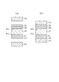
熱圧着機は図27(a)に示すように固定基板205の上面に支持された加熱媒体及び冷却媒体を流通する通路206aを有する下型206と、可動基板207の下面に装着され、かつ加熱媒体及び冷却媒体を流通する通路208aを有する上型208とにより構成されている。そして、下型206の上面に形成された凹部に素材209を収容した状態で、可動基板207を図27(b)に示すように下降させて素材209の上面に上型208を押圧し、通路206a,208aに加熱された油を通し、素材209を加熱する。上型208の成形面に形成されたパターンが素材209の上面に形成された後、通路206a,208aへの加熱油の供給を停止し、図27(c)に示すように通路206a,208aに冷却油の供給を行う。素材209が所定温度以下に冷却された後、上型208を上方に移動し、素材209の取り出しを行う。
【0004】
【発明が解決しようとする課題】
ところが、既存の射出成型機では肉厚が薄い大型品の成形加工が非常に難しく、ミクロンオーダーの凹凸のパターンの内部に樹脂材料が進入しにくく精度の良いパターンが形成されないという問題があった。又、上型と下型を離型する際にキャビティ内に収容された成形素材に形成されたパターンが崩れ易いという問題もあった。
【0005】
一方、図27に示す熱圧着機においては、下型206と上型208を型締状態で通路206a,208aに加熱用の油を供給して加熱した後、通路206a,208aに冷却用の油を供給して冷却する。このため、素材209内部の温度分布が均一なため例えば光学特性の良い製品が得られる反面、下型206と上型208の加熱時間と冷却時間が長くなり転写能率を向上することができないという問題があった。
【0006】
又、従来の転写装置として、素材をパターン成形板とともに加熱板により挟んで加熱を行った後、加熱室から素材、パターン成形板及び加熱板を積層状態で加熱室から出して冷却装置の冷却室内に移動させて冷却するようにした方法も提案されている。
【0007】
しかし、この製造方法は加熱装置から冷却装置へ移動する間に素材が内部まで加熱されてしまうので、製品の熱歪による変形が生じて製品としての価値が低減するという問題があった。又、加熱時間と冷却時間が長くなり製造能率を向上することができないという問題もあった。
【0008】
本発明は、上記従来の技術に存する問題点を解消して、転写能率を向上することができるとともにパターンの転写を精度よく行うことができる転写装置を提供することにある。
【0010】
【課題を解決するための手段】
上記問題点を解決するために、請求項1に記載の発明は、素材の表裏両面のうち少なくとも片面に接触されて、素材の片面に所定のパターンを成形可能なパターン成形手段と、上記素材及びパターン成形手段の上面側及び下側に位置して該パターン成形手段が前記素材に接触された状態で該素材及びパターン成形手段を加熱するための上下一対の加熱手段と、前記上側の加熱手段の上側及び下側の加熱手段の下側に位置して前記素材に対し前記パターン成形手段を押圧する上下一対のパターン押圧手段と、前記上側の加熱手段の上側及び下側の加熱手段の下側に位置して前記パターン押圧手段による素材の押圧状態で該素材を冷却するための上下一対の素材冷却手段とを備え、前記加熱手段と素材冷却手段は個別に形成され、前記加熱手段による素材の加熱工程において、前記上側のパターン押圧手段は前記上側の加熱手段から上方に離隔し、前記下側のパターン押圧手段は、前記下側の加熱手段から下方に離隔した位置に保持されるようになっていることを要旨とする。
【0011】
請求項2に記載の発明は、請求項1において、前記パターン成形手段は素材の表裏両面に対応して配設されるようにしたことを要旨とする。
請求項3に記載の発明は、請求項1又は2において、前記加熱手段はパターン押圧手段が作動される以前に作動位置から退避位置に切り換え可能に構成されていることを要旨とする。
【0012】
請求項4に記載の発明は、請求項1〜3のいずれか1項において、前記パターン成形手段、加熱手段、パターン押圧手段及び素材冷却手段は、減圧室を形成するケースの内部に収容され、前記ケースは、支持テーブルと、この支持テーブルの上面に配設された下部筒体と、上部昇降テーブルと、この上部昇降テーブルの下面に配設され、かつ前記下部筒体に嵌合又は突合せ可能な上部筒体と、下部筒体及び上部筒体の周面又は突合せ面間に介在されたシールリングとによって形成されていることを要旨とする。
【0013】
請求項5に記載の発明は、請求項4において、前記支持テーブルは、基盤の上面に対し位置切換機構によって位置の切り換え可能に装着され、該支持テーブルの上面には前記下部筒体が複数カ所に配設され、該下部筒体は、上部筒体と対応する転写位置と、該転写位置から離隔した素材をセットする準備位置と、転写を終えた素材を取り出す取出位置との間で切り換え可能に構成されていることを要旨とする。
【0014】
請求項6に記載の発明は、請求項1〜5のいずれか1項において、前記加熱手段は下部加熱板及び上部加熱板によって構成され、両加熱板の左右両側端部には、加熱面と反対側に指向するように折り曲げ部が形成され、下部加熱板及び上部加熱板を取り付けるブラケットに形成した収容溝に前記折り曲げ部を進入してクランプ板によってクランプするようになっていることを要旨とする。
【0015】
請求項7に記載の発明は、請求項1〜6のいずれか1項において、前記冷却手段は下部冷却体及び上部冷却体によって構成され、両冷却体は、加熱手段による加熱動作を停止した後に、数秒間は素材の冷却を抑制する冷却抑制手段を備えていることを要旨とする。
【0016】
請求項8に記載の発明は、請求項1〜7のいずれか1項において、前記パターン押圧手段は、素材の表面に沿って押圧力を平均化するためのフローティング機構を備えていることを要旨とする。
【0017】
請求項9に記載の発明は、請求項5において、前記準備位置又は取出位置と対応して、素材及びパターン成形手段のうち少なくとも素材を、加熱手段としての下部加熱板の上面へ搬入するとともに、転写済みの素材を前記下部加熱板の上面から搬出するためのローダー機構が設けられていることを要旨とする。
【0018】
請求項10に記載の発明は、請求項9において、前記ローダー機構は、横方向に往復動されるとともに、昇降動作されるチャック機構を備え、チャック機構は素材をクランプして昇降するクランプ機構と、パターン成形手段を吸着して昇降する吸着把持機構とにより構成されていることを要旨とする。
【0019】
請求項11に記載の発明は、請求項2〜10のいずれか1項において、基盤には案内レールを介して下部転写ユニットが転写位置と準備位置との間で位置の切り換え可能に装着され、前記基盤には昇降板を介して上部転写ユニットが昇降可能に装着され、前記下部転写ユニットは、前記案内レールに沿って移動される支持テーブルと、該支持テーブルの上面に装着された下部冷却体と、前記支持テーブルに対し前記下部冷却体の上面に接離可能に装着された下部加熱板とにより構成され、前記上部転写ユニットは前記昇降板に対しロック機構を介して脱着可能に装着された取付板と、該取付板の下面に装着された上部冷却体と、前記取付板に対し前記上部冷却体の下面に接離可能に装着された上部加熱板とにより構成され、前記転写位置の側方には素材をセットする準備位置が設けられ、該準備位置には、前記ロック機構のロック状態を解除することにより前記昇降板から分離され、かつ前記案内レールにより下部転写ユニットと共に前記転写位置から準備位置に移動された上部転写ユニットを反転してその保守点検を行うための反転機構が設けられていることを要旨とする。
【0024】
【発明の実施の形態】
(第1実施形態)
以下、本発明を具体化した転写装置の第1実施形態を図1〜図5に従って説明する。
【0025】
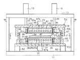
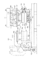
図3に示すように、平板状の基盤11の上面には円柱状をなす複数(第1実施形態では四本)の案内コラム12が上下方向に互いに平行に基盤11の四隅部に立設されている。各案内コラム12の上端部には平板状の天板13が水平に支持固定されている。前記案内コラム12〜12には下部昇降テーブル14が水平状態に、かつ各案内コラム12〜12に沿って上下方向に移動可能に装着されている。この下部昇降テーブル14の下方には複数箇所に下部昇降シリンダ15が上向きに立設され、各下部昇降シリンダ15のピストンロッド16によって前記下部昇降テーブル14が昇降動作されるようになっている。前記下部昇降テーブル14の上面には後述する下部転写ユニット17が装設されている。
【0026】
前記各案内コラム12〜12には上部昇降テーブル18が水平状態のまま上下方向の往復案内移動可能に装着されている。前記天板13の上面には複数の上部昇降シリンダ19が下向きに装着され、各上部昇降シリンダ19のピストンロッド20は、天板13を貫通して前記上部昇降テーブル18の上面に連結され、上部昇降テーブル18を上下方向に往復動するようになっている。前記上部昇降テーブル18の下面には後述する上部転写ユニット21が装着されている。
【0027】
次に、前記下部転写ユニット17及び上部転写ユニット21の構成を説明する。
前記下部昇降テーブル14の上面には左右一対の取付板22が互いに平行に取り付けられている。この取付板22の対向する内側面には絶縁板23を介してブラケット24が取り付けられ、このブラケット24の上端部間にはステンレススチール製の下部加熱板25が架設され、図示しないネジにより下部加熱板25がブラケット24に固定されている。前記下部加熱板25の左右両端部に電気的に接続されたリード線26は、案内板27によって挟着されている。前記取付板22、絶縁板23、ブラケット24、リード線26及び案内板27は図示しないボルトにより締め付け固定されている。
【0028】
前記左右一対の案内板27の内側面には素材冷却手段としての機能とパターン押圧手段としての機能を備えた下部冷却体29の両端部が上下方向の案内移動可能に装着されている。この下部冷却体29は、下部昇降テーブル14の下面に取り付けた下部加圧シリンダ30のピストンロッド31によって上下方向の往復動可能に支持されている。ピストンロッド31の上端部と前記下部冷却体29との間には例えば球面軸受け或いはユニバーサルジョイント等よりなるフローティング機構32が装着されている。前記下部冷却体29には多数の通水路29aが形成され、第1実施形態では冷却水を通過させるようになっている。
【0029】
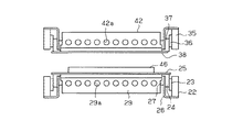
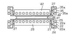
次に、前記上部転写ユニット21について説明すると、上部昇降テーブル18の下面には左右一対の取付板35が互いに平行に取り付けられ、両取付板35の内側面には絶縁板36を介してブラケット37が取り付けられている。このブラケット37の下端部間にはステンレススチール製の上部加熱板38の両端部が接触され、図示しないネジにより上部加熱板38がブラケット37に固定されている。前記ブラケット37の左右両端部に電気的に接続されたリード線39は案内板40によって挟着されている。前記取付板35、絶縁板36、ブラケット37、リード線39及び案内板40は、図示しないボルトにより締め付け固定されている。前記左右一対の案内板40の内側面には素材冷却手段としての機能とパターン押圧手段としての機能を備えた上部冷却体42の両端部が上下方向の案内移動可能に装着されている。この上部冷却体42は、上部昇降テーブル18の上面に取り付けた上部加圧シリンダ43のピストンロッド44によって上下方向の往復動可能に支持されている。前記上部冷却体42には多数の通水路42aが形成され、第1実施形態では冷却水を通過させるようになっている。前記ピストンロッド44の下端部と上部冷却体42との間には、例えば球面軸受け或いはユニバーサルジョイント等よりなるフローティング機構45が設けられている。
【0030】
前記下部加熱板25及び上部加熱板38の表面には、図示しないが例えば酸化アルミ或いは窒化アルミ等が溶射され、絶縁層が形成されている。
前記下部加熱板25と上部加熱板38との間には素材46が配設され、下部加熱板25と素材46の間には下部のパターン成形手段としてのパターン成形板47が介在されている。上部加熱板38と素材46の間には上部のパターン成形手段としてのパターン成形板48が介在されるようになっている。前記パターン成形板47,48の素材46側の表面には例えばミクロンオーダーの凹凸模様が形成され、前記素材46の表裏両面に同様の凹凸模様を転写可能となっている。パターン成形板47,48は凹凸模様が形成された原型に対し、例えばニッケル・クロム鍍金を行って、鍍金部分を剥離し、それをパターン成形板の基板に接着することにより形成されている。
【0031】
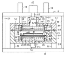
図3,図4に示すように前記下部転写ユニット17及び上部転写ユニット21等の各部材は、箱型のケース51によって遮蔽され、ケース51の内部を減圧室52としている。前記ケース51の前面には図4に示すように開口53が設けられ、この開口53は蓋54によって開閉されるようにしている。図示しないがケース51と蓋54の間にはシール部材が介在されている。
【0032】
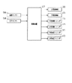
図5は転写装置の制御ブロック回路を示す。減圧室52内において下部加熱板25及び上部加熱板38と対応して設けられた温度センサー56は、制御装置57に検出された温度信号を入力するようになっている。前記下部加圧シリンダ30及び上部加圧シリンダ43には圧力センサー58が設けられ、この圧力センサー58の圧力信号が制御装置57に入力されるようになっている。前記下部加熱板25及び上部加熱板38による素材46の加熱温度は、前記温度センサー56の信号によって制御装置57が下部加熱板25及び上部加熱板38の通電電力及び通電時間を制御することにより例えば60℃〜230℃までの間で制御するようになっている。一般的には加熱温度は150℃〜160℃に設定される。又、前記制御装置57は加熱時間の制御の他、冷却開始と温度勾配の制御等を行うようになっている。圧力センサー58によって下部冷却体29及び上部冷却体42による素材46への押圧力が測定され、この測定信号が制御装置57に入力され、押圧力を制御するようになっている。
【0033】
次に、前記のように構成した転写装置についてその動作を説明する。
最初に、下部昇降シリンダ15及び上部昇降シリンダ19を動作させて、下部昇降テーブル14及び上部昇降テーブル18を所定高さ位置に保持する。又、下部加圧シリンダ30及び上部加圧シリンダ43を動作させて下部冷却体29及び上部冷却体42を下部加熱板25及び上部加熱板38からそれぞれ離隔させる。
【0034】
この状態において下部加熱板25の上面に図1(a)に示すようにパターン成形板47を載置し、このパターン成形板47の上面に素材46を載置する。さらに素材46の上面にパターン成形板48を載置する。
【0035】
次に、図4に示す開口53を蓋54によって閉鎖し減圧室52内を図示しないコンプレッサを作動させて減圧する。
その後、上部昇降シリンダ19を作動させて上部昇降テーブル18を下方に移動させ、上部加熱板38の下面が図1(b)に示すようにパターン成形板48の上面に接触した状態で上部昇降シリンダ19を停止させる。この状態では図2(a)に示すように、素材46の表裏両面にパターン成形板47のパターン47aとパターン成形板48のパターン48aが接触している。
【0036】
この状態において下部加熱板25及び上部加熱板38に交流又は直流電力を通電してジュール熱を発生させ、パターン成形板47及びパターン成形板48を加熱するとともに、素材46の表裏両面の表層部のみを加熱して軟化させる。この表層部の加熱領域の深さは、下部加熱板25及び上部加熱板38への通電時間の調整によって調整が可能である。
【0037】
この状態において下部加圧シリンダ30及び上部加圧シリンダ43を作動させ、図1(c)に示すように下部冷却体29及び上部冷却体42を下部加熱板25の下面と上部加熱板38の上面に接触させ所定の力で押圧する。この押圧によって、図2(b)に示すように、パターン成形板47,48のパターン47a,48aに軟化している素材46の一部が進入して所定のパターンが形成される。
【0038】
前記押圧力は素材46の材質あるいはパターンの深さによって、例えば1kg/cm2〜10kg/cm2の範囲に適宜に設定される。前記下部加圧シリンダ30及び上部加圧シリンダ43の作動に先立って下部加熱板25及び上部加熱板38への通電が停止され加熱動作が停止される。その後、図示しない水源及び給水配管を通して下部冷却体29及び上部冷却体42の通水路29a,42aに冷却水が供給される。このため下部冷却体29によって下部加熱板25、パターン成形板47及び素材46の下層部が冷却されるとともに、上部冷却体42によって上部加熱板38、パターン成形板48及び素材46の表層部が冷却される。
【0039】
前記素材46が素材46の軟化点の温度以下に冷却されたら前記下部昇降シリンダ15、上部昇降シリンダ19及び下部加圧シリンダ30及び上部加圧シリンダ43を動作させて、図1(a)に示すように初期状態と同様の状態に復帰する。この状態で、蓋54を開放して、素材46、パターン成形板47及びパターン成形板48を下部加熱板25の上面から取り出す。その後、素材46からパターン成形板47とパターン成形板48を分離することにより所望するパターンを備えた導光板等の板状製品を製造することができる。
【0040】
上記第1実施形態の転写装置によれば、以下のような特徴を得ることができる。
(1)第1実施形態では、前記下部昇降テーブル14の上面に下部加熱板25を配設し、この下部加熱板25の下方に下部冷却体29を配設し、前記下部加熱板25の上面にパターン成形板47を介して素材46を支持した。この素材46の上面にパターン成形板48を載置するようにした。又、前記パターン成形板48の上方に上部加熱板38を配設し、その上方に上部冷却体42を配設した。このため、素材46及びその上下両面に接触されたパターン成形板47及びパターン成形板48のみを下部加熱板25及び上部加熱板38によって加熱すればよいので、熱効率を向上することができるとともに、加熱時間を大幅に短縮することができ、転写作業の能率を高めることができる。又、加熱されて軟化した素材46の表面にパターン成形板47,48を押圧してパターン47a,48aを転写するようにしたので、パターンの形成を精度よく行うことができる。
【0041】
(2)第1実施形態では、下部加熱板25及び上部加熱板38によって素材46の表層部のみを加熱した状態で、素材46に対しパターン成形板47及びパターン成形板48を下部冷却体29及び上部冷却体42によって押圧し冷却するようにした。このため、素材46の中心部が加熱される以前にパターン成形板47,48のパターン47a,48aを素材46の表層部に転写することができる。このため素材46の中心部の加熱による素材46の熱歪によって素材46が変形するのを防止することができ、製品の品質を向上することができる。
【0042】
(3)第1実施形態では、下部加熱板25及び上部加熱板38を外側方向から下部冷却体29及び上部冷却体42によって冷却するようにした。このため、必要最小限の下部加熱板25、上部加熱板38、パターン成形板47,48及び素材46のみを冷却すればよく、素材46の中心部が加熱される以前に素材46の表層部を所定温度以下に冷却することができ、冷却時間を大幅に短縮することができ、この点からも転写作業の能率を高めることができる。
【0043】
(4)第1実施形態では、下部加圧シリンダ30のピストンロッド31と下部冷却体29との間にフローティング機構32を介在し、上部加圧シリンダ43のピストンロッド44と上部冷却体42との間にフローティング機構45を介在した。このため、素材46に対する下部冷却体29と上部冷却体42との押圧が適正に行われ、素材46の板厚寸法が適正に保持され、この点からも製品の品質を向上することができる。
【0044】
(5)第1実施形態では、ケース51内に減圧室52を設けて転写作業中において、減圧するようにしたので、例えば150℃前後に加熱された空気が焼けて酸化して微細な塵埃となっても、それが素材46の表面に付着するのを防止することができる。
【0045】
(6)第1実施形態では、パターン冷却手段を構成する下部冷却体29及び上部冷却体42に対し、パターン押圧手段としての機能を兼用させたので、部品点数を低減し構成を簡素化することができる。
(第2実施形態)
次に、この発明の第2実施形態を図6及び図7に基づいて説明する。なお、以下の各実施形態においては、前に説明した実施形態と同一の機能を有する部材については、同一の符号を付して説明を省略する。
【0046】
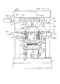
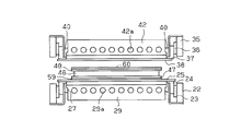
前記基盤11の上面には支持ブロック62を介して固定の支持テーブル63が水平に配設されている。この支持テーブル63の上面には前記下部転写ユニット17が装着されている。前記基盤11の上面の外周縁寄りには複数の支柱64が立設され、各支柱64の上端部には前記天板13が所定位置に支持されている。
【0047】
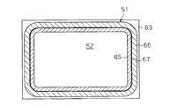
前記支持テーブル63の上面には、図7に示すように平面ほぼ四角筒状の下部筒体65が前記下部転写ユニット17を囲繞するように溶接により連結されている。前記上部昇降テーブル18の下面には、前記下部筒体65と対応するように、かつこの下部筒体65の外周面の形状と相似状に形成された上部筒体66が上部転写ユニット21を囲繞するように溶接により連結されている。前記下部筒体65の上部外周面にはオーリング67を収容するための溝65aが形成されている。オーリング67に上部筒体66の内周面が摺接されるようになっている。前記支持テーブル63のピストンロッド31を挿通する孔、及び上部昇降テーブル18のピストンロッド44を貫通する孔には、シール性を保持するためのオーリング67a,67bが配設されている。
【0048】
第2実施形態では前記上部昇降テーブル18、支持テーブル63、下部筒体65、上部筒体66及びオーリング67,67a,67b等によって前記減圧室52を区画形成するケース51が形成されている。
【0049】
従って、第2実施形態では前記下部転写ユニット17及び上部転写ユニット21を収容するための減圧室52の容積が小さくなるため、減圧作業時間を短くすることができ、転写作業の能率を向上することができる。又、広い空間を減圧するのと比較して動力の損失を低減することもできる。
(第3実施形態)
この第3実施形態においては、第2実施形態において、図8に示すように支持テーブル63に対し下部筒体65を一体に形成し、上部昇降テーブル18に対し上部筒体66を一体に形成し、前記天板13の上面に上部加圧シリンダ43を配置し、ピストンロッド44を上部昇降テーブル18の中央部に設けたボス部18aに貫通するようにしている。この第3実施形態では、減圧室52を形成するケース51の部品点数を低減して、製造及び組み付け作業を容易に行いコストの低減を図ることができる。
(第4実施形態)
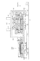
次に、図9に基づいて第4実施形態を説明する。
【0050】
この第4実施形態においては、前記基盤11の上面に対して二本(図において一本のみ図示)の案内レール68を互いに平行に、かつ水平方向に敷設するとともに、この案内レール68の上部にスライドブロック69を介して前記支持テーブル63を水平方向の往復動可能に支持している。前記支持テーブル63の上面に対し前記下部転写ユニット17を所定間隔をおいて二箇所に装着している。
【0051】
さらに、前記基盤11の上面には、シリンダ70が水平方向に、かつ前記案内レール68と平行に配設され、このシリンダ70のピストンロッド71の先端部を前記支持テーブル63の端部に取り付けた連結板72に連結している。前記案内レール68、支持テーブル63及びシリンダ70等によって一対の下部転写ユニット17,17を準備位置P1、転写位置P2及び取出位置P3の間で切り換える位置切換機構を構成している。
【0052】
従って、この第4実施形態では、転写位置P2にある一方の下部転写ユニット17によってワークの転写作業を行っている間に、準備位置P1にある別の下部転写ユニット17の下部加熱板25の上面に素材46、パターン成形板47,48を支持することにより、転写作業の準備を行うことができる。又、一方の素材46に対する転写作業が完了した後に上部昇降シリンダ19を作動して上部昇降テーブル18、上部転写ユニット21及び上部筒体66等を上方に移動させた状態で、前記シリンダ70を作動しピストンロッド71により支持テーブル63を図9において右方向に移動する。これによって、待機していた下部転写ユニット17が右方向の転写位置P2に移動されて、転写作業が行われる。この転写作業中において、右側の取出位置P3に移動された一方の下部転写ユニット17の下部加熱板25の上面から転写作業を終えた素材46、パターン成形板47,48を搬出する。
【0053】
その後、一方の下部転写ユニット17に対し準備作業が可能となるので、図9の右側の取出位置P3が準備位置P1となり、左側の準備位置P1が取出位置P3となる。
【0054】
上記第4実施形態では準備作業と転写作業及び転写作業と取出作業を並行して行うことができ、作業能率を向上することができる。
(第5実施形態)
次に、図10〜図12に基づいてこの発明の第5実施形態を説明する。
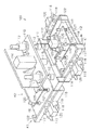
【0055】
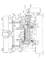
図10は転写装置全体を示す斜視図、図11は転写機構部の縦断面図、図12は素材46のチャック機構109を示す斜視図である。
図11に示すように、前記スライドブロック69と支持テーブル63との間には、エアクション式のフローティング機構73が設けられている。前記案内コラム12には昇降支持板81がスライダー82によって上下方向の往復動可能に装着され、この昇降支持板81には前記ピストンロッド44が上下方向に貫通固定されている。前記上部昇降テーブル18は前記案内コラム12に対しスライダー83によって昇降動作可能に支持されている。前記昇降支持板81にはボルト84が下向きに緩く貫通され、その下端雄ネジ部が前記上部昇降テーブル18に螺合されている。前記ボルト84の外周面にはコイルばね85が巻き取着され、上部昇降テーブル18と昇降支持板81を離隔する方向に付勢している。
【0056】
前記下部加熱板25は前記支持テーブル63に対しフローティング機構91によって支持されている。前記上部加熱板38は上部筒体66に対しフローティング機構91Aによって支持されている。前記下部筒体65には端子金具92が貫通され、リード線93によって下部加熱板25に接続されている。前記基盤11には転写位置P2にある下部転写ユニット17の端子金具92と対応するように通電機構94が装着されている。この通電機構94は転写位置P2に移動された端子金具92をクランプする一対のクランプ部材95及び96を連結ピン97によって連結するとともに、シリンダ98によって前記クランプ部材95及び96を開閉するようにしている。そして、トランス99からリード線100を介して前記端子金具92に電流を供給するようになっている。
【0057】
図10に示すように転写機構の前方にはベルトコンベヤー103が設けられ、素材46、パターン成形板47,48等の材料を搬入するようになっている。前記ベルトコンベヤー103の先端部左右両側には支持テーブル104が配設され、材料を載置することができるようになっている。前記支持テーブル104と対応するように、前記素材46等の材料を支持テーブル104から準備位置P1に移動された下部転写ユニット17に移し替えるローダー機構105が装設されている。このローダー機構105は、取出位置P3に移動された下部転写ユニット17から転写済みの素材46を取り出して一時的に貯留する貯留位置P4へ移し替えるための機能を有している。前記ローダー機構105は所定位置に水平方向に配設されたフレーム106と、このフレーム106の側面に取り付けられた案内レール107と、この案内レール107に沿ってロッドレスシリンダ108により位置の切り換え可能に装着されたチャック機構109とによって構成されている。
【0058】
次に、図12に基づいて前記チャック機構109について説明する。
前記案内レール107によって案内移動される取付基板110には、昇降ブロック111が案内ロッド112及び案内筒113によって昇降可能に支持され、昇降用シリンダ114のロッド115によって昇降動作されるようになっている。前記昇降ブロック111の右側面には一対の取付板116が水平方向に互いに平行に支持されている。この取付板116にはクランプ板117が支持ロッド118及び支持筒119によって水平方向の往復動可能に支持され、クランプ用シリンダ120のロッド121によってクランプ板117を水平方向に往復動するようになっている。前記クランプ板117の左右両端部にはアングル状のクランプ爪122が溶接等により取り付けられている。従って、左右及び前後計四つのクランプ爪122によって素材46の四隅部をクランプするようになっている。この実施形態では、前記取付板116、クランプ板117、支持ロッド118、支持筒119、クランプ用シリンダ120、及びクランプ爪122等によって、素材46のクランプ機構K1が構成されている。
【0059】
前記昇降ブロック111の側面にはブラケット125が水平に片持ち支持され、その下方には取付板126が昇降可能に支持されている。この取付板126の四隅部には吸盤127が装着され、下部加熱板25の上面に載置されるパターン成形板47又は素材46の上面に載置されるパターン成形板48を吸着保持するようになっている。前記ブラケット125には取付板126に連結された案内ロッド128を貫通する案内筒129が取り付けられ、ブラケット125の上面に取付けたシリンダ130のロッド131によって取付板126及び吸盤127を昇降動作するようになっている。この実施形態では、前記ブラケット125、取付板126、案内ロッド128、案内筒129、シリンダ130等によってパターン成形板47,48の吸着把持機構K2が構成されている。
【0060】
前記昇降ブロック111の左側面にも前記クランプ機構K1及び吸着把持機構K2と同様の機構が装着されている。従って、下部筒体65内部に収容されたが下部加熱板25に対して、同時に2つの素材46を載置して2つの転写作業を同時に行うことができる。
【0061】
この第5実施形態においては、最初に、一対の吸着把持機構K2によって前記支持テーブル104の上面に搬入されたパターン成形板47を吸着して、準備位置P1にある下部転写ユニット17の下部加熱板25の上面にパターン成形板47を搬入する作業が行われる。次に、クランプ機構K1によって支持テーブル104の上面に搬入された素材46をクランプして、前記パターン成形板47の上面に搬入する作業が行われ。さらに、前記吸着把持機構K2によって前記支持テーブル104の上面に搬入されたパターン成形板48を吸着して、素材46の上面に搬入する作業が行われる。
【0062】
又、取出位置P3にあるパターン成形板48、素材46、パターン成形板47の貯留位置P4への移動も前記クランプ機構K1及び吸着把持機構K2によって同様に行われる。
【0063】
さらに、図11において、上部加圧シリンダ43が作動されると、ピストンロッド44により昇降支持板81が下方に移動される。上部筒体66がオーリング67に接触されると、ケース51内に減圧室52が形成される。そして、ピストンロッド44がさらに下方に移動されると、上部転写ユニット21が下方に移動され、下部加熱板25と上部加熱板38の間に素材46、パターン成形板47,48が挟着され、転写作業が行われる。このとき、フローティング機構91,91Aにより前記挟着が均一圧力で行われ、転写作業の精度が向上する。
【0064】
この第5実施形態においては、案内レール68に沿って準備位置P1、転写位置P2、取出位置P3との間で位置切り換えされる一対の下部転写ユニット17の下部加熱板25への材料の供給と、貯留位置P4への移動を自動的に迅速かつ確実に行うことができ、転写作業の能率を向上することができる。
(第6実施形態)
次に、図13〜図15に基づいてこの発明の第6実施形態を説明する。
【0065】
図14に示すように前記案内コラム12には昇降板141が案内筒142によって昇降可能に支持され、この昇降板141の下面に上部転写ユニット21が取り外し可能に装着されている。この昇降板141の下面には取付板143が後述するロック機構160により取り付けられている。この取付板143の下面には円柱状をなする案内部材144を介して前記上部冷却体42が連結されている。該案内部材144の外周面には前記上部昇降テーブル18のボス部18aが上下方向の移動可能に装着され、前記上部昇降テーブル18と取付板143との間には、前述したボルト84及びコイルばね85が装着されている。なお、図13においては、前記ボルト84、コイルばね85及びロック機構160等は省略されている。
【0066】
前記昇降板141は昇降機構151によって昇降動作されるようになっている。この昇降機構151について説明すると、前記天板13の端部にはサーボモータ152が取り付けられ、これよって回転されるボールネジ153が天板13の下面に固定した軸受154によって回転可能に支持されている。前記天板13の下面には案内レール155が水平に取り付けられ、前記ボールネジ153に螺合されたボールネジナット157に取り付けたスライダー156を水平方向に案内移動するようになっている。前記昇降板141とスライダー156との間には連結リンク158が揺動可能に連節されている。前記天板13の中心部には下向きにバランスシリンダ159が取り付けられ、そのピストンロッドが前記昇降板141に連結されている。そして、前記昇降機構151のサーボモータ152による昇降板141の昇降動作を開始する際に、昇降板141の昇降動作が円滑に行われるようになっている。
【0067】
前記昇降板141の下面には前記上部転写ユニット21の取付板143を該昇降板141にロックするためのロック機構160が装着されている。このロック機構160は、昇降板141の下面に固定したブラケット160aと、該ブラケット160aに取り付けられたシリンダ160bと、前記ブラケット160aに取り付けられ、かつシリンダ160bにより前後動されるロック爪160cとにより構成されている。前記ロック機構160は図14に示すように左右に各一対設けられ、取付板143の下面を計四つのロック爪160cにより昇降板141との間でクランプすることにより上部転写ユニット21を昇降板141に取り付けるようにしている。前記上部転写ユニット21は、保守点検の際に前記ロック機構160のロック状態を解除すことによって前記昇降板141から分離されるようになっている。
【0068】
図13に示すように基盤11の端部には転写位置P2から準備位置P1に移動された下部転写ユニット17及び取り外されて下部転写ユニット17の上面に載置された上部転写ユニット21の保守点検を行う際に上方へ上部転写ユニット21を反転するための反転機構161が装着されている。この反転機構161について説明すると、基盤11の端部に立設した取付台162には、反転アーム163が支持軸164によって水平位置と垂直位置との間で往復回動可能に支持されている。前記取付台162には反転アーム163の反転用のサーボモータ165が配設されている。前記反転アーム163の下面には上部転写ユニット21の取付板143を反転アーム163に取り付けるための取付板166が設けられ、該取付板166には前記取付板143をクランプするための計四つのロック機構167が装着されている。各ロック機構167は図13において簡略化されているが、前記ロック機構160と同様に構成されている。
【0069】
前記取付台162の下端部と前記反転アーム163の基端部との間には、該反転アーム163の反転動作を円滑に行うための緩衝用のシリンダ169が連節されている。
【0070】
図13に示すように、下部転写ユニット17及び上部転写ユニット21は、案内レール68に沿って転写位置P2から準備位置P1に移動されるので、前記通電機構94が上下二箇所に装着されている。
【0071】
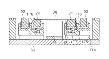
図15に示すように、前記支持テーブル63の上面には取付板174を介して支持ブロック175が支持され、この支持ブロック175に形成した収容孔175aには絶縁材よりなる横断面がU字状の昇降筒体176が収容されている。この昇降筒体176の底面と収容孔175aの底面との間にはバネ177が介在され、昇降筒体176を弾性的に支持している。前記昇降筒体176の内部には取付部材178が嵌入され、複数の取付部材178の上面に前記下部加熱板25が取り付けられている。前記支持ブロック175の別の位置に設けた収容孔175bにはリード線26の取付部材179が収容されている。
【0072】
従って、第6実施形態では、ロック機構160による上部転写ユニット21のロックを解除することにより、昇降板141から上部転写ユニット21を取り外すことができる。又、取り外された上部転写ユニット21を準備位置P1に移動した後、前記反転機構161によって上部転写ユニット21の姿勢を変更することができ、上部転写ユニット21の保守点検作業を容易に行うことができる。
【0073】
さらに、支持ブロック175に対し昇降筒体176及びバネ177を介して下部加熱板25を支持するようにしたので、下部加熱板25の熱膨張を吸収することができ、下部加熱板25の熱変形を防止して転写作業を精度よく行うことができる。
【0074】
なお、本実施形態は以下のように変更してもよい。
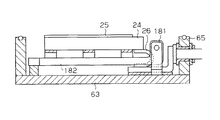
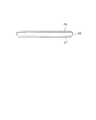
○ 図16に示すように支持テーブル63の上面に対しブラケット181を支持し、このブラケット181の上端部に回動テーブル182の端縁を連結ピンにより上下方向の傾動可能に支持し、この回動テーブル182の上面にブラケット24を介して下部加熱板25を支持するようにしてもよい。この別例においては、回動テーブル182を上方に回動させることによって下部加熱板25の姿勢を変更して保守点検作業を容易に行うことができる。
【0075】
○ 図17に示すように下部加熱板25の上面に所定のパターンを形成することにより下部加熱板25自体にパターン成形板47の機能を兼用させる。又、上部加熱板38の下面に所定のパターンを形成することにより上部加熱板38自体にパターン成形板48の機能を兼用させるようにしてもよい。この場合には装置の部品点数を低減して、転写装置の製造及び転写作業を容易に行うことができる。この場合には、第5実施形態の吸着把持機構K2を省略することができる。
【0076】
○ 図18に示すように下部加熱板25とパターン成形板47の間及び上部加熱板38とパターン成形板48との間にゴム或いは樹脂製の絶縁緩衝板59,60を介在するようにしてもよい。この場合には下部冷却体29及び上部冷却体42による押圧の際の素材46の変形を防止することができる。
【0077】
○ 図19に示すように素材46の下面を支持テーブル63により直接支持するようにしてもよい。この場合には素材46の上面の片面のみにパターンを形成する場合に使用することができる。又、支持テーブル63と素材46の間にパターン成形板47を設け、パターン成形板48を省略してもよい。
【0078】
○ 図20に示すように上部加熱板38を加熱工程の終了直後に水平方向側方に退避した状態で上部冷却体42を下方に移動するようにしてもよい。この別例では上部加熱板38を冷却しなくてもよいので、素材46の冷却時間を短縮することができる。
【0079】
○ 図21に示すように、素材46に対しパターン成形板47とパターン成形板48が食み出さないように接触してもよい。この別例では素材46の外周部の上下の角部の変形を防止することができる。
【0080】
○ 図22に示すように、下部冷却体29の内部にピン191を収容し、バネ192によってピン191を上方に付勢するとともに、前記ピン191の上端面によって前記下部加熱板25の下面を支持するようにしてもよい。なお、バネ192の下端部はバネ受193によって位置規制されている。又、前記上部冷却体42の内部にも前記ピン191、バネ192及びバネ受193と同様の部材を装着してもよい。
【0081】
上記別例では前記ピン191によって下部加熱板25及び上部加熱板38が複数カ所において支持されるので、下部加熱板25及び上部加熱板38のそりを防止して素材46及びパターン成形板47,48を適正に挟着することができ、転写作業を適正に行うことができる。
【0082】
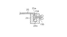
○ 図23に示すように、前記ブラケット24に収容溝24aをブラケット24の長手方向に形成するとともに、収容溝24aの内部に下部加熱板25の左右両端部に加熱面と反対方向に形成された折り曲げ部25a(右端部のみ図示)を挿入する。前記収容溝24aにクランプ板194を収容する。該クランプ板194を前記折り曲げ部25aの側面に押圧するためのクランプボルト195を前記ブラケット24に螺合する。上部加熱板38の左右両端部にも折り曲げ部25aと同様の折り曲げ部を設けてクランプ板194によりクランプするようにしてもよい。
【0083】
上記別例においては、帯状のクランプ板194を適数本のクランプボルト195によって折り曲げ部25aに押圧して固定することができ、ブラケット24に対する下部加熱板25の脱着作業を容易に行うことができる。
【0084】
○ 図24に示すように、取付板22及び取付板35に対し冷却水を通すための通路22a,35aを形成してもよい。この場合には、ブラケット24及びブラケット37を冷却して下部加熱板25及び上部加熱板38の外周部の冷却を適正に行い、冷却ムラをなくして転写作業を精度よく行うことができる。
【0085】
○ 図25に示すように、下部冷却体29の上面側の層に熱伝導度の低い材料よりなる冷却抑制手段としての冷却抑制板200を接合するとともに、前記上部冷却体42の下面側の層にも同じく冷却抑制板200を接合するようにしてもよい。
【0086】
上記別例においては、素材46の冷却を開始した直後においては、前記冷却抑制板200によって素材46の冷却が数秒間(例えば3〜5秒)緩やかに行われ、その後、下部冷却体29及び上部冷却体42によって冷却が迅速で行われる。この結果、素材46の冷却動作が適正に行われて、転写作業を適正に行うことができる。
【0087】
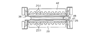
○ 図26に示すように、下部冷却体29及び上部冷却体42に冷却抑制手段としてのヒーター201を埋設し、素材46の冷却動作を開始した直後において、前記ヒーター201を作動して素材46が急激に冷やされるのをなくしてもよい。冷却抑制手段として、前記冷却抑制板200あるいはヒーター201に代えて、ゴム製の冷却抑制板を下部冷却体29の上面や上部加熱板38の上面に載置するようにしてもよい。又、加熱動作を停止した後に、下部冷却体29及び上部冷却体42の作動を数秒間だけ遅らせるようにしてもよい。
【0088】
○ 図示しないが、前記下部冷却体29及び上部冷却体42による素材46及びパターン成形板47,48の冷却工程において、押圧力を最初の数秒間は例えば20トンで行い、それ以降は例えば100トンで行うようにしてもよい。この別例では、最初に弱い押圧力で冷却を開始するので、素材46から下部冷却体29及び上部冷却体42に伝導される熱が抑制され、転写精度を向上することができる。
【0089】
○ 図示しないが、例えば下部冷却体29及び上部冷却体42にハニカム構造を適用して、軽量化するようにしてもよい。
○ 前記パターン成形板47及びパターン成形板48の材料として例えばクローム合金等の絶縁性の高い材料を用いてもよい。
【0090】
○ 前記下部加熱板25、上部加熱板38及びパターン成形板48の清掃を行うための装置を設けてもよい。この清掃装置の一例として、粘着テープを回転させたり、空気を噴射させたり、回転ブラシを回転しつつ移動させたりするようにしてもよい。
【0091】
○ IC基板の素材に対しICチップの埋め込みを行うようにしてもよい。
○ 減圧室52内に除湿装置を設けてもよい。
○ 減圧室52内にオゾンを収容した状態で転写作業を行うようにしてもよい。
【0092】
○ 加熱手段として加熱板以外に超音波振動により素材46の表面を加熱したり、素材46を直接振動させて加熱したりしてもよい。
○ 下部加熱板25と上部加熱板38の加熱温度をそれぞれ個別に制御するようにしてもよい。この場合には素材46の上下両面の加熱温度を同じにしたときに素材46に反りがでる場合には、温度差をもたせて反りを無くすことができる。
【0093】
○ 一つのケース51の内部に下部転写ユニット17及び上部転写ユニット21を上下方向又は横方向に複数箇所に配設してもよい。ソータに収容された素材を一枚つづ転写装置に供給して転写するようにしてもよい。
【0094】
○ 前記実施形態では下部冷却体29及び上部冷却体42にパターン押圧手段としての機能を付与したが、パターン押圧手段と冷却手段を別体で構成してもよい。
【0095】
○ パターン押圧手段としての機能を、下部加熱板25及び上部加熱板38に付与したり、上部加熱板38の自重やパターン成形板48の自重をパターン押圧手段として用いたりしてもよい。
【0096】
○ 前記下部昇降シリンダ15、下部加圧シリンダ30に代えて、例えばスプリングを用いたり、上部昇降シリンダ19、上部加圧シリンダ43に代えて例えばスプリングを用いたりしてもよい。又、上部昇降テーブル18の自重を利用して押圧力を素材46に作用させるようにしてもよい。さらに、パターン押圧手段として電動モータにより回転されるピニオンとラックを用いたり、その他のアクチュエータを用いたりしてもよい。
【0097】
(定義)この明細書において、パターン形成手段は、凹凸の模様以外に単なる平面のパターンも含むものとする。
【0098】
【発明の効果】
以上詳述したように、請求項1〜11記載の発明は、転写能率を向上することができるとともにパターンの形成を精度よく行うことができる。
【0099】
又、請求項6記載の発明は、上記効果に加えて製品の熱による変形を抑制することができる。
【図面の簡単な説明】
【図1】 (a)〜(c)はこの発明の第1実施形態の転写装置の素材の転写工程を示す説明図。
【図2】 (a)及び(b)は第1実施形態の要部の拡大断面図。
【図3】 第1実施形態の転写装置全体を示す正断面図。
【図4】 第1実施形態の転写装置全体を示す側断面図。
【図5】 第1実施形態の制御装置を示すブロック回路図。
【図6】 この発明の第2実施形態を示す縦断面図。
【図7】 図6の1−1線断面図。
【図8】 この発明の第3実施形態を示す縦断面図。
【図9】 この発明の第4実施形態を示す正断面図。
【図10】 この発明の第5実施形態を示す斜視図。
【図11】 図10の要部の断面図。
【図12】 図10のチャック機構の斜視図。
【図13】 この発明の第6実施形態を示す正面図。
【図14】 図13の要部の断面図。
【図15】 この発明の別例を示す断面図。
【図16】 この発明の別例を示す断面図。
【図17】 この発明の別例を示す部分正面図。
【図18】 この発明の別例を示す部分正面図。
【図19】 この発明の別例を示す部分正面図。
【図20】 この発明の別例を示す部分正断面図。
【図21】 この発明の別例を示す部分正面図。
【図22】 この発明の別例を示す部分正断面図。
【図23】 この発明の別例を示す部分断面図。
【図24】 この発明の別例を示す部分正面図。
【図25】 この発明の別例を示す部分正面図。
【図26】 この発明の別例を示す部分正面図。
【図27】 (a)〜(c)は従来の熱圧着機のパターン成形方法を示す説明図。
【符号の説明】
K1…クランプ機構、K2…吸着把持機構、P1…準備位置、P2…転写位置、P3…取出位置、11…基盤、17…下部転写ユニット、18…上部昇降テーブル、21…上部転写ユニット、24…ブラケット、24a…収容溝、25…下部加熱板、25a…折り曲げ部、29…下部冷却体、32,45,73,91…フローティング機構、38…上部加熱板、42…上部冷却体、46…素材、47,48…パターン成形板、47a,48a…パターン、51…ケース、52…減圧室、63…支持テーブル、65…下部筒体、66…上部筒体、105…ローダー機構、109…チャック機構、117…クランプ板、161…反転機構、194…クランプ板。[0001]
BACKGROUND OF THE INVENTION
The present invention relates to a transfer device capable of thermally transferring a predetermined pattern onto the surface of a flat plate-like material.
[0002]
[Prior art]
In recent years, resin-made light guide plates for generating a backlight are used for flat display panels such as liquid crystal display panels or organic electroluminescence display panels. The surface of the light guide plate has a micron-order concavo-convex pattern that reflects light output from the light source to generate a uniform backlight.
[0003]
The light guide plate having the pattern having the predetermined shape is manufactured by using an injection molding machine or a thermocompression bonding machine (hot press).
As shown in FIG. 27A, the thermocompression bonding machine is attached to the
[0004]
[Problems to be solved by the invention]
However, the existing injection molding machine has a problem in that it is very difficult to mold a large-sized product with a small thickness, and the resin material does not easily enter the concave and convex pattern on the order of microns, and a high-precision pattern cannot be formed. There is also a problem that when the upper mold and the lower mold are separated from each other, the pattern formed on the molding material accommodated in the cavity tends to collapse.
[0005]
On the other hand, in the thermocompression bonding machine shown in FIG. 27, the
[0006]
Also, as a conventional transfer device, after heating the material together with the pattern forming plate by the heating plate, the material, the pattern forming plate and the heating plate are taken out from the heating chamber in a stacked state and then the cooling chamber is cooled. There has also been proposed a method of cooling by moving to the position.
[0007]
However, this manufacturing method has a problem that since the raw material is heated to the inside while moving from the heating device to the cooling device, the product is deformed due to thermal strain and the value as a product is reduced. In addition, the heating time and the cooling time become long, and there is a problem that the production efficiency cannot be improved.
[0008]
An object of the present invention is to provide a transfer apparatus capable of solving the above-described problems in the prior art, improving transfer efficiency, and accurately transferring a pattern.
[0010]
[Means for Solving the Problems]
In order to solve the above-mentioned problems, the invention according to
[0011]
The gist of a second aspect of the present invention is that, in the first aspect, the pattern forming means is arranged corresponding to both the front and back surfaces of the material.
The invention according to claim 3 is the invention according to
[0012]
Invention of Claim 4 is set in any one of Claims 1-3, The pattern forming unit, the heating unit, the pattern pressing unit, and the material cooling unit are accommodated in a case forming a decompression chamber, and the case includes a support table and a lower cylindrical body disposed on the upper surface of the support table. An upper lifting table, an upper cylinder disposed on the lower surface of the upper lifting table and fitted or butted against the lower cylinder, and a circumferential surface or a butting surface of the lower cylinder and the upper cylinder. Formed by intervening seal ring It is a summary.
[0013]
The invention described in claim 5 5. The support table according to claim 4, wherein the support table is mounted on the upper surface of the base so that the position can be switched by a position switching mechanism, and the lower cylinder is disposed at a plurality of locations on the upper surface of the support table. Is configured to be switchable between a transfer position corresponding to the upper cylindrical body, a preparation position for setting a material separated from the transfer position, and a take-out position for taking out the material after the transfer. It is a summary.
[0014]
The invention according to claim 6 6. The heating means according to any one of
[0015]
The invention described in
[0016]
The invention according to claim 8 provides: 8. The pattern pressing means according to
[0017]
The invention according to claim 9 is: 6. In accordance with claim 5, corresponding to the preparation position or the take-out position, at least the material of the material and the pattern forming means is carried onto the upper surface of the lower heating plate as the heating means, and the transferred material is transferred to the lower heating plate. A loader mechanism is provided for unloading from the top surface. It is a summary.
[0018]
The invention according to claim 10 is: 10. The loader mechanism according to claim 9, wherein the loader mechanism includes a chuck mechanism that is reciprocated in the lateral direction and is moved up and down, and the chuck mechanism lifts and lowers by clamping a material and lifting and lowering the pattern forming means. The suction gripping mechanism It is a summary.
[0019]
The invention according to
[0024]
DETAILED DESCRIPTION OF THE INVENTION
(First embodiment)
Hereinafter, a first embodiment of a transfer device embodying the present invention will be described with reference to FIGS.
[0025]
As shown in FIG. 3, a plurality of (four in the first embodiment) guide
[0026]
An upper elevating table 18 is mounted on each of the
[0027]
Next, the configuration of the
A pair of left and right mounting
[0028]
On both inner surfaces of the pair of left and
[0029]
Next, the
[0030]
Although not shown, for example, aluminum oxide or aluminum nitride is thermally sprayed on the surfaces of the
A
[0031]
As shown in FIGS. 3 and 4, the members such as the
[0032]
FIG. 5 shows a control block circuit of the transfer apparatus. A
[0033]
Next, the operation of the transfer apparatus configured as described above will be described.
First, the lower elevating
[0034]
In this state, the
[0035]
Next, the
Thereafter, the upper elevating
[0036]
In this state, the
[0037]
In this state, the
[0038]
The pressing force depends on the
[0039]
When the
[0040]
According to the transfer device of the first embodiment, the following features can be obtained.
(1) In the first embodiment, the
[0041]
(2) In the first embodiment, only the surface layer portion of the
[0042]
(3) In the first embodiment, the
[0043]
(4) In the first embodiment, the floating
[0044]
(5) In the first embodiment, the
[0045]
(6) In the first embodiment, since the
(Second Embodiment)
Next, a second embodiment of the present invention will be described with reference to FIGS. In the following embodiments, members having the same functions as those of the previously described embodiments are denoted by the same reference numerals and description thereof is omitted.
[0046]
A fixed support table 63 is horizontally disposed on the upper surface of the
[0047]
As shown in FIG. 7, a lower
[0048]
In the second embodiment, the upper elevating table 18, the support table 63, the
[0049]
Accordingly, in the second embodiment, the volume of the
(Third embodiment)
In the third embodiment, in the second embodiment, as shown in FIG. 8, the lower
(Fourth embodiment)
Next, a fourth embodiment will be described based on FIG.
[0050]
In the fourth embodiment, two guide rails 68 (only one is shown in the figure) are laid parallel to each other and horizontally with respect to the upper surface of the
[0051]
Further, a
[0052]
Therefore, in the fourth embodiment, the upper surface of the
[0053]
Thereafter, preparation work is possible for one of the
[0054]
In the fourth embodiment, preparation work, transfer work, transfer work and take-out work can be performed in parallel, and work efficiency can be improved.
(Fifth embodiment)
Next, a fifth embodiment of the present invention will be described with reference to FIGS.
[0055]
FIG. 10 is a perspective view showing the entire transfer device, FIG. 11 is a longitudinal sectional view of the transfer mechanism portion, and FIG. 12 is a perspective view showing the
As shown in FIG. 11, an action
[0056]
The
[0057]
As shown in FIG. 10, a
[0058]
Next, the
An elevating
[0059]
A
[0060]
A mechanism similar to the clamp mechanism K1 and the suction gripping mechanism K2 is also mounted on the left side surface of the elevating
[0061]
In the fifth embodiment, first, the
[0062]
The movement of the
[0063]
Further, in FIG. 11, when the
[0064]
In the fifth embodiment, the material is supplied to the
(Sixth embodiment)
Next, a sixth embodiment of the present invention will be described with reference to FIGS.
[0065]
As shown in FIG. 14, an elevating
[0066]
The lifting
[0067]
A
[0068]
As shown in FIG. 13, at the end of the
[0069]
A
[0070]
As shown in FIG. 13, the
[0071]
As shown in FIG. 15, a support block 175 is supported on the upper surface of the support table 63 via a mounting
[0072]
Therefore, in the sixth embodiment, the
[0073]
Furthermore, since the
[0074]
In addition, you may change this embodiment as follows.
As shown in FIG. 16, the
[0075]
As shown in FIG. 17, by forming a predetermined pattern on the upper surface of the
[0076]
As shown in FIG. 18, rubber or resin insulating
[0077]
As shown in FIG. 19, the lower surface of the material 46 may be directly supported by the support table 63. In this case, it can be used when a pattern is formed only on one side of the upper surface of the
[0078]
As shown in FIG. 20, the
[0079]
As shown in FIG. 21, the
[0080]
As shown in FIG. 22, the
[0081]
In the above example, since the
[0082]
23. As shown in FIG. 23, the
[0083]
In the other example, the belt-
[0084]
As shown in FIG. 24,
[0085]
25, as shown in FIG. 25, a cooling
[0086]
In the other example, immediately after the cooling of the
[0087]
As shown in FIG. 26, immediately after the
[0088]
○ Although not shown, in the cooling process of the
[0089]
Although not shown, for example, a honeycomb structure may be applied to the
As the material of the
[0090]
A device for cleaning the
[0091]
○ An IC chip may be embedded in the material of the IC substrate.
A dehumidifier may be provided in the
The transfer operation may be performed in a state where ozone is accommodated in the
[0092]
As a heating means, in addition to the heating plate, the surface of the material 46 may be heated by ultrasonic vibration, or the
The heating temperatures of the
[0093]
In the
[0094]
In the embodiment, the
[0095]
The function as the pattern pressing unit may be imparted to the
[0096]
In place of the lower elevating
[0097]
(Definition) In this specification, the pattern forming means includes not only uneven patterns but also simple planar patterns.
[0098]
【The invention's effect】
As detailed above, claims 1-1 1 The described invention can improve transfer efficiency and can form a pattern with high accuracy.
[0099]
In addition to the above effects, the invention described in claim 6 can suppress deformation of the product due to heat.
[Brief description of the drawings]
FIGS. 1A to 1C are explanatory views showing a material transfer process of a transfer apparatus according to a first embodiment of the present invention;
FIGS. 2A and 2B are enlarged cross-sectional views of main parts of the first embodiment. FIGS.
FIG. 3 is a front sectional view showing the entire transfer apparatus according to the first embodiment.
FIG. 4 is a side sectional view showing the entire transfer apparatus according to the first embodiment.
FIG. 5 is a block circuit diagram showing the control device of the first embodiment.
FIG. 6 is a longitudinal sectional view showing a second embodiment of the present invention.
7 is a cross-sectional view taken along line 1-1 of FIG.
FIG. 8 is a longitudinal sectional view showing a third embodiment of the present invention.
FIG. 9 is a front sectional view showing a fourth embodiment of the invention.
FIG. 10 is a perspective view showing a fifth embodiment of the present invention.
11 is a cross-sectional view of the main part of FIG.
12 is a perspective view of the chuck mechanism of FIG.
FIG. 13 is a front view showing a sixth embodiment of the present invention.
14 is a cross-sectional view of the main part of FIG.
FIG. 15 is a sectional view showing another example of the present invention.
FIG. 16 is a sectional view showing another example of the present invention.
FIG. 17 is a partial front view showing another example of the present invention.
FIG. 18 is a partial front view showing another example of the present invention.
FIG. 19 is a partial front view showing another example of the present invention.
FIG. 20 is a partial front sectional view showing another example of the present invention.
FIG. 21 is a partial front view showing another example of the present invention.
FIG. 22 is a partial front sectional view showing another example of the present invention.
FIG. 23 is a partial sectional view showing another example of the present invention.
FIG. 24 is a partial front view showing another example of the present invention.
FIG. 25 is a partial front view showing another example of the present invention.
FIG. 26 is a partial front view showing another example of the present invention.
27A to 27C are explanatory views showing a pattern forming method of a conventional thermocompression bonding machine.
[Explanation of symbols]
K1 ... Clamping mechanism, K2 ... Adsorption gripping mechanism, P1 ... Preparation position, P2 ... Transfer position, P3 ... Extraction position, 11 ... Base, 17 ... Lower transfer unit, 18 ... Upper lift table, 21 ... Upper transfer unit, 24 ... Bracket, 24a ... receiving groove, 25 ... lower heating plate, 25a ... bent portion, 29 ... lower cooling body, 32, 45, 73, 91 ... floating mechanism, 38 ... upper heating plate, 42 ... upper cooling body, 46 ...
Claims (11)
上記素材及びパターン成形手段の上面側及び下面側に位置して該パターン成形手段が前記素材に接触された状態で該素材及びパターン成形手段を加熱するための上下一対の加熱手段と、
前記上側の加熱手段の上側及び下側の加熱手段の下側に位置して前記素材に対し前記パターン成形手段を押圧する上下一対のパターン押圧手段と、
前記上側の加熱手段の上側及び下側の加熱手段の下側に位置して前記パターン押圧手段による素材の押圧状態で該素材を冷却するための上下一対の素材冷却手段とを備え、
前記加熱手段と素材冷却手段は個別に形成され、前記加熱手段による素材の加熱工程において、前記上側のパターン押圧手段は前記上側の加熱手段から上方に離隔し、前記下側のパターン押圧手段は、前記下側の加熱手段から下方に離隔した位置に保持されるようになっていることを特徴とする転写装置。A pattern forming means capable of forming a predetermined pattern on one side of the material by contacting at least one side of the front and back surfaces of the material;
And a pair of upper and lower heating means for heating the said workpiece and the pattern forming means in a state in which located on the top side and the bottom side of the material and the pattern forming means is the pattern forming means is in contact with the material,
A pair of upper and lower pattern pressing means for pressing the pattern forming means against the material located on the upper side of the upper heating means and the lower side of the heating means ;
A pair of upper and lower material cooling means for cooling the material in a pressed state of the material by the pattern pressing means located on the upper side of the upper heating means and the lower side of the lower heating means ,
The heating means and the material cooling means are individually formed, in the material of the heating process by the heating means, the upper pattern pressing means is spaced upwardly from the heating means of the upper, the pattern pressing means of the lower, A transfer apparatus, wherein the transfer apparatus is held at a position spaced downward from the lower heating means .
Priority Applications (1)
| Application Number | Priority Date | Filing Date | Title |
|---|---|---|---|
| JP2003172521A JP4266328B2 (en) | 2002-06-17 | 2003-06-17 | Transfer device |
Applications Claiming Priority (2)
| Application Number | Priority Date | Filing Date | Title |
|---|---|---|---|
| JP2002176268 | 2002-06-17 | ||
| JP2003172521A JP4266328B2 (en) | 2002-06-17 | 2003-06-17 | Transfer device |
Publications (2)
| Publication Number | Publication Date |
|---|---|
| JP2004074775A JP2004074775A (en) | 2004-03-11 |
| JP4266328B2 true JP4266328B2 (en) | 2009-05-20 |
Family
ID=32032442
Family Applications (1)
| Application Number | Title | Priority Date | Filing Date |
|---|---|---|---|
| JP2003172521A Expired - Lifetime JP4266328B2 (en) | 2002-06-17 | 2003-06-17 | Transfer device |
Country Status (1)
| Country | Link |
|---|---|
| JP (1) | JP4266328B2 (en) |
Families Citing this family (10)
| Publication number | Priority date | Publication date | Assignee | Title |
|---|---|---|---|---|
| JP4469713B2 (en) * | 2004-12-20 | 2010-05-26 | コマツ産機株式会社 | Stamper mounting device and thermal transfer press machine |
| KR100892801B1 (en) * | 2005-02-25 | 2009-04-10 | 스미토모덴키고교가부시키가이샤 | Processing method of fine structure and processing equipment for fine structure |
| JP4858805B2 (en) * | 2005-06-30 | 2012-01-18 | 公益財団法人新産業創造研究機構 | Light guide plate manufacturing method, light guide plate, surface light source device using the same, light source panel for liquid crystal display, and liquid crystal display device |
| CN104317161A (en) * | 2005-12-08 | 2015-01-28 | 分子制模股份有限公司 | Method and system for double-sided patterning of substrates |
| JP4854313B2 (en) * | 2006-01-27 | 2012-01-18 | 東芝機械株式会社 | Control device in transfer device |
| US8814556B2 (en) | 2007-09-28 | 2014-08-26 | Toray Industries, Inc | Method and device for manufacturing sheet having fine shape transferred thereon |
| JP5267939B2 (en) * | 2009-02-03 | 2013-08-21 | 富士電機株式会社 | Imprint apparatus and imprint method |
| KR101796514B1 (en) * | 2016-03-21 | 2017-12-01 | 주식회사 신명프라텍 | Method for manufacturing clear files |
| CN108437308B (en) * | 2018-04-28 | 2024-01-30 | 南京金三力高分子科技有限公司 | Vulcanization molding die for printing ink printing transfer rubber pedal pad and manufacturing method |
| CN113459467B (en) * | 2021-08-06 | 2022-08-23 | 重庆万桥交通科技发展有限公司 | Extrusion molding cooling device for outer sheaths of stay cables |
Family Cites Families (16)
| Publication number | Priority date | Publication date | Assignee | Title |
|---|---|---|---|---|
| JPS55124626A (en) * | 1979-03-20 | 1980-09-25 | Matsushita Electric Ind Co Ltd | Production of and apparatus for mirror-finished resin plate |
| JPS57135137A (en) * | 1981-02-17 | 1982-08-20 | Asahi Chem Ind Co Ltd | Forming method for synthetic resin and apparatus therefor |
| JPH05375Y2 (en) * | 1987-02-20 | 1993-01-07 | ||
| JPH02282218A (en) * | 1989-04-24 | 1990-11-19 | Matsushita Electric Ind Co Ltd | Gap forming device |
| JP2828161B2 (en) * | 1993-12-16 | 1998-11-25 | 株式会社リコー | Plastic molding equipment |
| JP4014232B2 (en) * | 1994-08-03 | 2007-11-28 | 旭化成ケミカルズ株式会社 | Electromagnetic induction heating mold for resin molding |
| JP3401584B2 (en) * | 1994-09-22 | 2003-04-28 | 鈴木総業株式会社 | Equipment for manufacturing uneven sheet |
| JPH09239757A (en) * | 1996-03-13 | 1997-09-16 | Matsushita Electric Ind Co Ltd | Optical device molding apparatus and molding method |
| DE19648844C1 (en) * | 1996-11-26 | 1997-09-18 | Jenoptik Jena Gmbh | Forming microstructured components for embossing tool and formable material between chamber walls |
| JPH1158510A (en) * | 1997-08-20 | 1999-03-02 | Olympus Optical Co Ltd | Manufacture of bent resin tube |
| JP3243607B2 (en) * | 1998-07-02 | 2002-01-07 | 株式会社名機製作所 | Vacuum laminating apparatus and vacuum laminating method |
| JP2000141392A (en) * | 1998-11-09 | 2000-05-23 | Polymatech Co Ltd | Method for molding polymer composite material and magnetic field oriented press forming machine |
| JP2001079865A (en) * | 1999-09-17 | 2001-03-27 | Meiki Co Ltd | Vacuum laminating apparatus |
| JP2001310385A (en) * | 2000-04-28 | 2001-11-06 | Matsushita Electric Ind Co Ltd | Transfer molding method |
| JP3638514B2 (en) * | 2000-09-27 | 2005-04-13 | 株式会社東芝 | Transfer device, transfer cartridge, and transfer method |
| JP2002113775A (en) * | 2000-10-06 | 2002-04-16 | Dainippon Printing Co Ltd | Method for producing uneven sheet |
-
2003
- 2003-06-17 JP JP2003172521A patent/JP4266328B2/en not_active Expired - Lifetime
Also Published As
| Publication number | Publication date |
|---|---|
| JP2004074775A (en) | 2004-03-11 |
Similar Documents
| Publication | Publication Date | Title |
|---|---|---|
| CN102177010B (en) | Device and method for thermoforming by hot-plate heating | |
| JP4266328B2 (en) | Transfer device | |
| JP6272676B2 (en) | Bonding equipment | |
| JP2010123770A (en) | Component mounting apparatus and component mounting method | |
| CN106002606A (en) | Polishing and wax pasting machine for sapphire substrate | |
| JP2014231185A (en) | Resin molding apparatus and resin molding method | |
| WO2015104890A1 (en) | Automatic bonding apparatus | |
| WO2011089827A1 (en) | Bonding apparatus, bonding method, and computer storage medium | |
| JP2010212638A (en) | Manufacturing device for manufacturing semiconductor device and manufacturing method for manufacturing semiconductor device | |
| CN219703990U (en) | Battery tray welding fixture | |
| US20070158871A1 (en) | Press-molding apparatus, mold, and press-molding method | |
| JP4302447B2 (en) | Press machine | |
| JP2010123771A (en) | Component mounting device and component mounting method | |
| CN115692261A (en) | An adaptive leveling pressure applying device and method for electrostatic bonding | |
| CN119593067A (en) | Seed crystal bonding device and method | |
| CN219076563U (en) | Corner board forming equipment | |
| JPH08288337A (en) | Chip bonder and bonding method | |
| KR102343647B1 (en) | Flexible display divice bonding table structure | |
| KR102277383B1 (en) | Wide area forming device | |
| CN221497359U (en) | Special ceramic metallization device | |
| JP2005077426A (en) | Substrate bonding apparatus and substrate bonding method | |
| JP3565793B2 (en) | Ultrasonic vibration bonding resonator | |
| CN118658797B (en) | Laser bonding device | |
| CN223322237U (en) | A hot pressing device for flexible circuit board and adhesive backing | |
| CN222004206U (en) | Hemp plate heating insert production system |
Legal Events
| Date | Code | Title | Description |
|---|---|---|---|
| A621 | Written request for application examination |
Free format text: JAPANESE INTERMEDIATE CODE: A621 Effective date: 20060426 |
|
| A977 | Report on retrieval |
Free format text: JAPANESE INTERMEDIATE CODE: A971007 Effective date: 20080513 |
|
| A131 | Notification of reasons for refusal |
Free format text: JAPANESE INTERMEDIATE CODE: A131 Effective date: 20080610 |
|
| A521 | Request for written amendment filed |
Free format text: JAPANESE INTERMEDIATE CODE: A523 Effective date: 20080811 |
|
| A131 | Notification of reasons for refusal |
Free format text: JAPANESE INTERMEDIATE CODE: A131 Effective date: 20081118 |
|
| A521 | Request for written amendment filed |
Free format text: JAPANESE INTERMEDIATE CODE: A523 Effective date: 20090119 |
|
| TRDD | Decision of grant or rejection written | ||
| A01 | Written decision to grant a patent or to grant a registration (utility model) |
Free format text: JAPANESE INTERMEDIATE CODE: A01 Effective date: 20090210 |
|
| A01 | Written decision to grant a patent or to grant a registration (utility model) |
Free format text: JAPANESE INTERMEDIATE CODE: A01 |
|
| A61 | First payment of annual fees (during grant procedure) |
Free format text: JAPANESE INTERMEDIATE CODE: A61 Effective date: 20090216 |
|
| R150 | Certificate of patent or registration of utility model |
Ref document number: 4266328 Country of ref document: JP Free format text: JAPANESE INTERMEDIATE CODE: R150 Free format text: JAPANESE INTERMEDIATE CODE: R150 |
|
| FPAY | Renewal fee payment (event date is renewal date of database) |
Free format text: PAYMENT UNTIL: 20120227 Year of fee payment: 3 |
|
| FPAY | Renewal fee payment (event date is renewal date of database) |
Free format text: PAYMENT UNTIL: 20150227 Year of fee payment: 6 |
|
| R250 | Receipt of annual fees |
Free format text: JAPANESE INTERMEDIATE CODE: R250 |
|
| R250 | Receipt of annual fees |
Free format text: JAPANESE INTERMEDIATE CODE: R250 |
|
| R250 | Receipt of annual fees |
Free format text: JAPANESE INTERMEDIATE CODE: R250 |
|
| R250 | Receipt of annual fees |
Free format text: JAPANESE INTERMEDIATE CODE: R250 |
|
| EXPY | Cancellation because of completion of term |