JP4265723B2 - Frame structure of crawler type construction machine vehicle - Google Patents
Frame structure of crawler type construction machine vehicle Download PDFInfo
- Publication number
- JP4265723B2 JP4265723B2 JP2000246429A JP2000246429A JP4265723B2 JP 4265723 B2 JP4265723 B2 JP 4265723B2 JP 2000246429 A JP2000246429 A JP 2000246429A JP 2000246429 A JP2000246429 A JP 2000246429A JP 4265723 B2 JP4265723 B2 JP 4265723B2
- Authority
- JP
- Japan
- Prior art keywords
- cross member
- frame
- pair
- rear cross
- body frame
- Prior art date
- Legal status (The legal status is an assumption and is not a legal conclusion. Google has not performed a legal analysis and makes no representation as to the accuracy of the status listed.)
- Expired - Fee Related
Links
Images

Classifications
-
- B—PERFORMING OPERATIONS; TRANSPORTING
- B62—LAND VEHICLES FOR TRAVELLING OTHERWISE THAN ON RAILS
- B62D—MOTOR VEHICLES; TRAILERS
- B62D55/00—Endless track vehicles
- B62D55/08—Endless track units; Parts thereof
- B62D55/10—Bogies; Frames
-
- B—PERFORMING OPERATIONS; TRANSPORTING
- B62—LAND VEHICLES FOR TRAVELLING OTHERWISE THAN ON RAILS
- B62D—MOTOR VEHICLES; TRAILERS
- B62D21/00—Understructures, i.e. chassis frame on which a vehicle body may be mounted
- B62D21/18—Understructures, i.e. chassis frame on which a vehicle body may be mounted characterised by the vehicle type and not provided for in groups B62D21/02 - B62D21/17
- B62D21/186—Understructures, i.e. chassis frame on which a vehicle body may be mounted characterised by the vehicle type and not provided for in groups B62D21/02 - B62D21/17 for building site vehicles or multi-purpose tractors
Landscapes
- Engineering & Computer Science (AREA)
- Chemical & Material Sciences (AREA)
- Combustion & Propulsion (AREA)
- Transportation (AREA)
- Mechanical Engineering (AREA)
- Architecture (AREA)
- Structural Engineering (AREA)
- Body Structure For Vehicles (AREA)
Description
【0001】
【発明の属する技術分野】
本発明は、主として履帯走行装置を備える建設機械における車輌のフレームに関するもので、全体剛性を強化できるとともに、基本形を崩すことなく車種バリエーションに応じて車体重心位置を最適箇所に設定できる構成の建設機械車輌のフレーム構造に関するものである。
【0002】
【従来の技術】
従来、履帯走行装置を備える建設機械車輌においては、エンジンと機械動力伝達装置を車体フレームに搭載して、動力伝達装置を搭載した車体フレームと左右履帯走行装置のトラックフレームとの間に、履帯駆動減速機を介在させて車体フレームとトラックフレームとを連結してなる構成とされている。このような車輌では、車体フレームとトラックフレームの連結取付位置が、履帯駆動減速機からの機械駆動伝動軸の位置により拘束されて、一義的に定まっている。
【0003】
【発明が解決しようとする課題】
このようなことから、従来の履帯走行装置を備える建設機械車輌では、トラックフレーム上の任意の位置を選択して車体フレームを連結取付することができないので、履帯接地長さ方向の適正な位置に車体重心が来るように、車体バランスの設定に腐心しなければならないという問題がある。
【0004】
さらに、前記した車体重心位置の設定は、接地長を長くしたバリエーション車種の履帯走行装置にすることで変化し、適性重心位置の設定のために車体改造が必要になるという問題もある。また、左右履帯の轍間距離を広げた履帯走行装置にすると、大幅な車体改造が強いられ、簡単な改造で済まされないという問題もある。
【0005】
一方、アメリカ特許第5894908号明細書では、上部車体フレームと下部トラックフレームを完全一体化して、全体剛性を強化した一体フレームを提起している。しかし、このような構成の場合、接地長を長くした履帯走行装置のバリエーション車種、左右履帯の軸間距離を広げた履帯走行装置のバリエーション車種を製作する際には、完全一体化フレーム全体の造り替えとなり、簡単な改造では得られない。
【0006】
本発明は、前述のような問題点に鑑みてなされたもので、上部車体フレームを最適重心位置が得られるようにトラックフレームの任意位置に置いて結合一体化を図れるようにするとともに、履帯走行装置のバリエーション車種に応じた改造を容易にできて、全体の剛性強化を可能とする履帯式建設機械車輌のフレーム構造を提供することを目的とするものである。
【0007】
【課題を解決するための手段および作用・効果】
前述された目的を達成するために、第1発明による履帯式建設機械車輌のフレーム構造は、
履帯式建設機械車輌の左右トラックフレームと車体フレームを剛構造一体化したフレーム構造であって、
左右に間隔を空けて並置される一対のトラックフレームは、長手方向の前部に二股の遊動輪取付フレーム部分を、中間部に下部転輪取付面を有する断面箱形のフレーム部分を、後部に前記中間部分から車体内方側にオフセットした油圧モータ内蔵の履帯駆動減速機取付部分をそれぞれ有する一体構成にてなるとともに、その左右のトラックフレーム間に跨げた前側クロスメンバーおよび後側クロスメンバーにて一体結合され、前記油圧モータ内蔵の履帯駆動減速機取付部分のオフセットはみだし個所が、前記後側クロスメンバーの後方面に一体結合され、前記左右のトラックフレームの間隔幅よりも小さく並置される左右一対の車体フレームメンバーが、前記前側クロスメンバーおよび後側クロスメンバーの上位置に跨げて一体結合され、前記左右一対のトラックフレームと前記左右一対の車体フレームメンバーが前記前側および後側クロスメンバーによって一体化された構成であることを特徴とするものである。
【0008】
また、第2発明による履帯式建設機械車輌のフレーム構造は、
履帯式建設機械車輌の左右トラックフレームと車体フレームを剛構造一体化したフレーム構造であって、
左右に間隔を空けて並置される一対のトラックフレームは、その左右のトラックフレーム間に跨げた前側クロスメンバーおよび後側クロスメンバーにて一体結合され、前記左右のトラックフレームの間隔幅よりも小さく並置される左右一対の車体フレームメンバーは、それぞれ縦板ビームからなり、その縦板ビームの長手方向二箇所に所要の間隔で前記前側クロスメンバーおよび後側クロスメンバーの上から嵌まり合う切欠きを有して、前記前側および後側クロスメンバーの上位置に跨げて一体結合され、前記左右一対のトラックフレームと前記左右一対の車体フレームメンバーが前記前側および後側クロスメンバーによって一体化され、
かつ前記左右の縦板ビームの前部側底面に底部プレートが渡されるとともに、前記左右の縦板ビームの後部側端面間に壁板と前記後側クロスメンバーの後面板メンバーとなる縦壁ビームが渡されて、前記左右の縦板ビーム後部と前記後側クロスメンバーとが結合されて一体化された構成であることを特徴とするものである。
【0009】
前記第1発明および第2発明においては、左右トラックフレームに前後クロスメンバーを所要の配置で直交させて結合するとともに、それら前後クロスメンバーに対してその上で車体フレームを直交させて結合する梯形状結合とされている。このように左右トラックフレーム,前後クロスメンバー,車体フレームをそれぞれ独立した骨格フレームとしているから、設計上の自由度が得られる。したがって、本発明によれば、例えばトラックフレームを長くした接地長の長い履帯走行装置に付替えた車輌、あるいは前後クロスメンバーの左右方向長さを長くして左右履帯走行装置の轍間距離を広くした車輌のように、車体バリエーションの変更が、独立した要部メンバーの変更のみで対応させることができ、その設計変更を容易にするという効果がある。しかも、トラックフレームに対する前後クロスメンバーの結合位置を適宜に調整設定することで、変更される製品に応じた車体の最適重心位置を任意に選定でき、合理的な車体構造が得られるという効果を奏する。
【0010】
また、第1発明においては、とりわけ、履帯駆動減速機取付部分を前記遊動輪および下部転輪取付フレーム部分と一体化したトラックフレームとされたから、前記減速機取付部分に取付られる履帯駆動輪の回転位置を精度良く位置決めできる利点がある。さらに、前記減速機取付部分を後側クロスメンバーの後方面に一体結合する構成とされたので強度的に保証される。
【0011】
また、第2発明によれば、左右一対の車体フレームメンバーである縦板ビームを、左右トラックフレームと一体結合する前後クロスメンバーに対して交叉状に一体結合させたので、左右トラックフレームと前後クロスメンバーとの歪みに対する抵抗を高め、全体の剛性を確保できるという効果を奏する。
【0012】
前記各発明において、前記前側クロスメンバーは、箱形断面構造のビームからなり、前記後側クロスメンバーは箱形断面構造の後面板メンバーを左右一対の車体フレームメンバーを構成する縦板ビーム後端間の後壁として上方に延設された縦壁ビーム部分を有するクロスメンバーであり、それら前側クロスメンバーの両端と後側クロスメンバーの両端が前記左右トラックフレームの側面にそれぞれ結合されるとともに、前記後側クロスメンバーの前記縦壁ビーム部分が左右一対の縦板ビームの後端面間に一体結合された構成であるのが好ましい。(第3発明)。
【0013】
このような構成によれば、後側クロスメンバーの縦壁ビーム部分が左右一対の車体フレームの縦板ビームと左右トラックフレームとに一体結合されているので、この縦壁ビーム部分を後方作業機の取付板部としても、作業時の動態応力および振動が後側クロスメンバー、車体フレームおよび左右トラックフレームと車体全体に分散して吸収されるという効果を奏する。
【0015】
前記車体フレームメンバーを構成する左右一対の縦板ビーム後端面と前記後側クロスメンバーとに跨って渡された縦壁ビームの外壁面に、後部プラットホームおよび後部アタッチメント取付の支持架台が設けられるのが好ましい(第4発明)。こうすると、車体フレームの後部に設けられる後部プラットホームおよび支持架台を介して後付けされるアタッチメントなどを安定状態で取付けることができる。
【0016】
また、前記車体フレームメンバーを構成する左右一対の縦板ビームに、前記前側および後側クロスメンバー間において箱形ビーム部分が形成され、その箱形ビーム部分の上面に作業機リフトシリンダの取付座を有する構成とされているのが良い(第5発明)。こうすると、車体フレームは、前後クロスメンバー間に位置する部分を、箱型構成にしたことで縦方向の剛性が向上し、作業機のリフトシリンダからの負荷に十分耐えることができる。
【0017】
さらに、前記車体フレームの縦板ビームにおける箱形ビーム部分は、その上面に設けられる作業機リフトシリンダの取付座下方から後側クロスメンバーに向かって断面が次第に大きくなるように構成されているのがよい(第6発明)。こうすると、作業機リフトシリンダ取付部に作用する応力を後側クロスメンバーとその後側クロスメンバーの箱形ビーム部分に向けて分散させることができ、必要以外の部分の構造を簡素化して軽量化を図ることができる。
【0018】
また、前記前側クロスメンバーは、車体フレームとトラックフレームとの間の箱形ビーム部分の前面側に、作業機フレームの取付座を有しているように構成されるのがよい(第7発明)。こうすると、作業機(例えばブルドーザのブレード)からの掘削反力を、箱型にされた前側クロスメンバーで受けるので、振動吸収作用が高く、車体フレームへの振動の伝播を軽減できる効果がある。
【0019】
【発明の実施の形態】
次に、本発明による履帯式建設機械車輌のフレーム構造の具体的な実施の形態につき、図面を参照しつつ説明する。なお、本実施例はブルドーザのフレーム構造について説明する。
【0020】
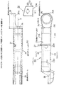
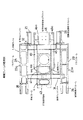
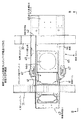
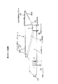
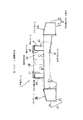
図1に本実施例にかかる履帯式建設機械車輌の車輌フレーム全体斜視図が示され、図2にトラックフレームを表わす側面図(a),平面図(b)およびA−A断面図(c)がそれぞれ示されている。図3に車輌フレームの底面図が、図4に車体フレームと前後クロスメンバーが組合わされた状態での平面図が、図5に図4のB−B視図が、図6に図1のC−C視断面図が、それぞれ示されている。
【0021】
本実施例のブルドーザは、トラックフレームに油圧モータ内蔵式の履帯駆動減速機を装備した履帯駆動手段による履帯走行式のブルドーザであって、車輌フレーム1は、履帯走行装置を支持する左右一対のトラックフレーム2A,2Bと、これらトラックフレーム2A,2Bを一体結合にするために、トラックフレーム2A,2B間に梯形状に渡した前後クロスメンバー31,32、およびその前後クロスメンバー31,32を跨いで前記左右トラックフレーム2A,2Bの間に格子状に配される左右一対の縦板ビームからなる車体フレーム4とを一体結合された構成である。
【0022】
前記トラックフレーム2A,2Bは、基本的に左右対称に構成されて、細部において一部の形状が異なっている。したがって、説明の都合上、図1において右側のフレーム2Aにより説明する。このトラックフレーム2Aは、図2(a)(b)(c)によって示されるように、下部転輪が臨む取付穴を複数形成した平面プレートメンバー23に、樋状に屈曲形成された主メンバー22の開口側を下に伏せて溶接され一体化した断面箱形フレーム部分21と、この断面箱形フレーム部分21の後端側に、履帯設置線aから一方側(車体内方側)にオフセットした位置に溶接接合される油圧モータ内蔵の履帯駆動減速機取付フレーム25部分と、前端側に二股状に形成されて溶接接合される遊動輪取付フレーム26とから構成されている。なお、前記断面箱形フレーム部分21の上面は、図2(c)によって示されるように外側(車体横方向)に向かって下がり勾配の斜面に形成されている。
【0023】
断面箱形フレーム部分21を構成する前記平面プレートメンバー23の下向き面23aには、所要の間隔で複数の取付穴23bが穿設され、これら取付穴23bによって下部転輪を支持する軸受(いずれも図示せず)が配設されるようにされている。また、断面箱形フレーム部分21の上面で内側寄りの長手方向中間の適当な位置には、少なくとも1個(この具体例では1個)の上部転輪支持ブラケット27が直立して設けられている。
【0024】
前後クロスメンバー31,32は、いずれも所要厚さの鋼板材で所要寸法の箱型構造にされて、両端を前記トラックフレーム2A,2Bの対向側面に梯形状に溶接結合されている。そして、前側クロスメンバー31の前側面には車体フレーム4とトラックフレーム2A,2Bとの間にそれぞれ作業機フレーム(図示せず)の基端部を接続固定するための取付座部が設けられ、その作業機フレームを接続する取付ボルト孔33が前後方向に複数設けられている。
【0025】
車体フレーム4は、所要長さ寸法の左右一対の縦板ビーム41,41を所要の間隔を隔てて平行に配されて、後端を後部支持板42(本発明の縦壁ビームに相当)で一体に結合され、前端を前部繋ぎ部材43によって結合され、かつ底部で底板44(本発明の底部プレートに相当)によって結合されてなる。そして、左右の縦板ビーム41,41には、外側面から後側クロスメンバー32と前記後部支持板42とにわたって、ボックス構造部45,45(本発明の箱形ビーム部分に相当)を一体溶接結合され、それらボックス構造部45,45の上面の先端部位置に作業機リフトシリンダ取付ブラケット47が設置されている。
【0026】
前記後部支持板42は、前記後側クロスメンバー32の後面板を上方に延在して、左右一対の前記縦板ビーム41,41後端面および縦板ビームのボックス構造部45,45の後端面間にわたって一体結合した後壁であって、後方作業機の取付支持部となり、後方作業機取付ブラケット46(本発明における後部プラットホームおよび後部アタッチメント取付の支持架台に相当)が一体に結合されている。
【0027】
このように構成される左右トラックフレーム2A,2Bと前後クロスメンバー31,32および車体フレーム4は、それぞれ個々に製作されてユニットとされ、これらを纏めて所定の寸法で溶接によって結合されて車輌フレーム1を構成する。
【0028】
その組合わせの態様を説明すれば、まず所定寸法に溶接結合される車体フレーム4は、その基本寸法に基づいて左右一対の縦板ビーム41,41に、前後クロスメンバー31,32の配置間隔に合わせて、それらクロスメンバー31,32の嵌り得る切込み部b,cを設けたものを作製する。なお、縦板ビーム41の外側部にはボックス構造部45が形成される。こうした左右縦板ビーム41,41を所定の間隔で平行に配し、前部繋ぎ部材43と底部底板44とで結合して枠組み構造にされる。
【0029】
一方、前側クロスメンバー31は、予め設定される履帯走行装置の轍間距離に対応した長さ寸法で箱形ビームに溶接構成され、後側クロスメンバー32は予め設定される履帯走行装置の轍間距離に対応した長さ寸法でコ形ビームに溶接構成される。そして、前側クロスメンバー31には、前述のように前側面に作業機フレームの基部が締結できる取付座部34と取付ボルト孔33が設けられる。
【0030】
このように構成された前後クロスメンバー31,32は、前記車体フレーム4の縦板ビーム41,41に形成された切込み部b,cにそれぞれ嵌め合わせるとともに、後側クロスメンバー32のコ形開口部を塞いでボックス状ビームを形成する後面板から縦板ビーム41,41および縦板ビームのボックス構造部45,45の後端面間に跨って後部支持板42をあてがい、前後クロスメンバー31,32と、縦板ビーム41,41と後部支持板42とを溶接結合して、図4に示されるように格子状に一体化される。なお、後方作業機取付ブラケット46は作業の手順に応じて、事前もしくは組立後に取付られる。このようにすることによって、簡単な断面構造の縦板ビームを用いて剛性の高いフレーム構造とすることができる。しかも、左右縦板ビーム41,41における外側部に形成されるボックス構造部45は、上面に固着立設される作業機のリフトシリンダ取付ブラケット47の位置下部から後側クロスメンバー32との結合位置まで下がり勾配で次第に広がる形状にされるので、そのリフトシリンダ取付ブラケット47の取付基部に作用する作業機のリフトシリンダによる負荷を作用方向に分散させて、局部的に内部応力が発生するのを防止して過剰な強度メンバーにすることなく合理的に構成できるのである。
【0031】
また、左右のトラックフレーム2A,2Bは、前述のように板曲げ加工された主メンバー22と底部を形成する支持メンバー23とを溶接結合して箱型構造にされた断面箱形フレーム部分21に、前後端で減速駆動機取付フレーム25と遊動輪取付フレーム26を結合させ、左右両トラックフレーム2A,2Bに対応した細部で所要寸法に一体構成される。このように構成されたトラックフレーム2A,2Bは、その側面に前記クロスメンバー31,32によって梯形状に構成された車体フレーム4と、そのクロスメンバー31,32の各端面を突合せて溶接結合することにより、所定の轍間距離でトラックフレーム2A,2Bを平行に配置して、それらトラックフレーム2A,2B間内で前後クロスメンバー31,32を介し上側に車体フレーム4が組み付けられ、全体が梯形状で一体構造にされた剛性のすこぶる高い車輌フレーム1に構成することができる。
【0032】
このように構成される本実施例の車輌フレーム1は、前述のように、各主要メンバーが直線的に形成されたユニット構造のものを梯形状に組合わせて結合される構成であるので、例えば接地長の長い履帯走行装置を要する車種、あるいは左右履帯の轍間距離を広げた履帯走行装置を備える車種というように、車種バリエーションに対応させることが容易になる。
【0033】
すなわち、基本的に変更の少ない車体フレームに対して、例えば接地長の長い履帯走行装置を要する車種の場合には、トラックフレーム2A,2Bの断面箱形フレーム部分21を所要長さのものにして、車体フレーム4と両トラックフレーム2A,2Bを結合させる前後クロスメンバー31,32の前後位置をその車種に見合った位置に変更すれば、車体フレーム4を構成する縦板ビーム41,41に対する前後クロスメンバー31,32との結合用の切込み部b,c位置を所要個所に設定して設けることにより、車体重心位置を最適位置に選定して枠組み構成できることになる。
【0034】
また、左右履帯の轍間距離を広げた履帯走行装置を備える車種の場合には、左右トラックフレーム2A,2Bを相互に接続結合させる前後クロスメンバー31,32とは側面部での結合によって構成できるので、その前後クロスメンバー31,32の長さ寸法を所要長さに変更したものを用いることにより目的を達成できる。なお、この実施例による車輌フレーム1は、履帯駆動減速機取付フレーム25に対して油圧モータ内蔵の減速駆動機(図示せず)を装着して、履帯走行装置の駆動ができるようにされるので、車体フレーム4の要所、例えば底板44部に油圧ユニット(図示せず)を搭載して、この油圧ユニットからは後部支持板42に設けられる透かし穴を通じて油圧ホースにより前記油圧モータに接続すれば、駆動機を駆動させることが可能になるので、車種バリエーションに応じてフレームメンバーを任意に変更することができる利点がある。
【0035】
このように、各部メンバーの組合わせ変更の自由度が高く、しかも全体としての結合構成については、常に主要メンバーを同様にして最適な寸法に変更することで、それに伴う車体としての重心位置の選定が任意に行えるという従来にない新しい構成とされ、しかも、その結合に際して前述のように格子状に組合わせることによって過度な部材構成とすることなく全体を一体化して剛性を高められることができるという効果を奏する。
【0036】
また、本発明では、各部(トラックフレーム,前後クロスメンバーおよび車体フレームを形成する縦板ビーム)をそれぞれユニット化して製作できるので、製作に際しての合理化を図ることができるという利点がある。もちろん、それら各部の部材について最適寸法を選定することにより軽量化でき、それに伴ない生産コストの低減と、全体重量の低減により車輌としての駆動時における消費エネルギーの削減にも役立つという効果が得られることになる。
【0037】
以上の説明においては、ブルドーザの車輌フレームについて記載したが、本発明に趣旨に則すれば、他の建設機械車輌にも採用することが可能である。
【図面の簡単な説明】
【図1】図1は、本実施例にかかる建設機械車輌の車輌フレーム全体斜視図である。
【図2】図2は、トラックフレームを表わす側面図(a),平面図(b)およびA−A断面図(c)である。
【図3】図3は、車輌フレームの底面図である。
【図4】図4は、車体フレームと前後クロスメンバーが組合わされた状態での平面図である。
【図5】図5は、図4のB−B視図である。
【図6】図6は、図1のC−C視断面図である。
【符号の説明】
1 車輌フレーム
2A,2B トラックフレーム
4 車体フレーム
21 トラックフレームの断面箱形フレーム部分
22 主メンバー
23 支持メンバー
24 支持端板
25 履帯駆動減速機取付フレーム
26 遊動輪取付フレーム
31 前側クロスメンバー
32 後側クロスメンバー
34 作業機の取付座部
41 縦板ビーム
42 後部支持板
43 前部繋ぎ部材
45 ボックス構造部
46 後方作業機取付ブラケット[0001]
BACKGROUND OF THE INVENTION
The present invention mainly relates to a vehicle frame in a construction machine provided with a crawler track traveling device, and can improve the overall rigidity and can set the position of the center of gravity of the vehicle body at an optimum location according to the vehicle type variation without breaking the basic shape. The present invention relates to a vehicle frame structure.
[0002]
[Prior art]
Conventionally, in a construction machine vehicle equipped with a crawler traveling device, an engine and a mechanical power transmission device are mounted on the vehicle body frame, and the crawler belt drive is performed between the vehicle body frame equipped with the power transmission device and the track frame of the left and right crawler traveling devices. The vehicle body frame and the track frame are connected via a reduction gear. In such a vehicle, the connection mounting position between the body frame and the track frame is uniquely determined by being constrained by the position of the mechanical drive transmission shaft from the crawler belt drive speed reducer.
[0003]
[Problems to be solved by the invention]
For this reason, in a construction machine vehicle equipped with a conventional crawler belt traveling device, an arbitrary position on the track frame cannot be selected and the vehicle body frame cannot be connected and attached. There is a problem that the body balance must be set so that the center of gravity of the vehicle body comes.
[0004]
Further, the setting of the center of gravity position of the vehicle body described above is changed by using a crawler traveling device of a variation vehicle type having a long contact length, and there is a problem that the vehicle body needs to be modified to set the appropriate center of gravity position. In addition, if the crawler traveling device has a wider distance between the left and right crawler belts, there is a problem that a large amount of vehicle body modification is forced and simple modification is not sufficient.
[0005]
On the other hand, US Pat. No. 5,894,908 discloses an integrated frame in which the upper body frame and the lower track frame are completely integrated to enhance the overall rigidity. However, in the case of such a configuration, when manufacturing a variation model of a crawler traveling device with a longer ground contact length or a variation of a crawler traveling device with a wider inter-axis distance between the left and right crawler tracks, It becomes a replacement and cannot be obtained with a simple modification.
[0006]
The present invention has been made in view of the above-described problems. The upper body frame is placed at an arbitrary position of the track frame so that an optimum center of gravity position can be obtained, and can be integrated and tracked. It is an object of the present invention to provide a frame structure for a crawler type construction machine vehicle that can be easily modified in accordance with the vehicle model of the apparatus and can enhance the overall rigidity.
[0007]
[Means for solving the problems and actions / effects]
In order to achieve the above-described object, the frame structure of the crawler construction machine vehicle according to the first invention is:
It is a frame structure in which the left and right track frames and the body frame of the crawler type construction machine vehicle are rigidly integrated,
A pair of track frames juxtaposed at a distance from each other on the left and right, a bifurcated idler wheel mounting frame part at the front in the longitudinal direction, a cross-sectional box-shaped frame part having a lower wheel mounting surface at the middle part, and a rear part together comprising the hydraulic motor internal crawler drive reduction gear mounting portion of the intermediate portion is offset to the vehicle body inner side at the integral structure having respectively at the front cross member and a rear cross member has Matage between its right and left track frames A pair of left and right , which are integrally coupled, and an offset protruding portion of a crawler belt drive speed reducer mounting portion with a built-in hydraulic motor is integrally coupled to the rear surface of the rear cross member, and juxtaposed to be smaller than the interval width of the left and right track frames. body frame members are integrally coupled Matage a position on the front cross member and a rear cross member, front Is characterized in that said pair of left and right body frame members and a pair of right and left track frames are integrated constituted by the front and rear cross members.
[0008]
Further, the frame structure of the crawler type construction machine vehicle according to the second invention is:
It is a frame structure in which the left and right track frames and the body frame of the crawler type construction machine vehicle are rigidly integrated,
A pair of track frames juxtaposed with a gap between them on the left and right are joined together by a front cross member and a rear cross member straddling the left and right track frames, and are juxtaposed smaller than the width of the left and right track frames. Each of the pair of left and right body frame members is formed of a vertical plate beam, and has notches that fit from above the front cross member and the rear cross member at two predetermined positions in the longitudinal direction of the vertical plate beam. And it is integrally coupled across the upper position of the front and rear cross members, the pair of left and right track frames and the pair of left and right body frame members are integrated by the front and rear cross members,
And a bottom plate is passed to the front side bottom surface of the left and right vertical plate beams, and a vertical wall beam serving as a rear plate member of a wall plate and the rear cross member is provided between rear side end surfaces of the left and right vertical plate beams. The left and right vertical plate beam rear portions and the rear cross member are combined and integrated with each other.
[0009]
In the first and second aspects of the invention , the front and rear cross members are coupled to the left and right track frames in a required arrangement so as to be orthogonal to each other, and the vehicle body frame is orthogonally coupled to the front and rear cross members. It is considered as a bond. Thus, since the left and right track frames, the front and rear cross members, and the body frame are independent frame frames, a degree of freedom in design can be obtained. Therefore, according to the present invention, for example, a vehicle replaced with a crawler traveling device with a long grounding length with a longer track frame, or the longitudinal length of the front and rear cross members is increased to increase the distance between the left and right crawler traveling devices. As in the case of the vehicle, the change of the vehicle body variation can be dealt with only by the change of the independent main member, and the design change can be facilitated. Moreover, by appropriately adjusting and setting the coupling position of the front and rear cross members with respect to the track frame, it is possible to arbitrarily select the optimum center of gravity position of the vehicle body according to the product to be changed, and there is an effect that a rational vehicle body structure can be obtained. .
[0010]
In the first aspect of the invention, in particular, since the track drive reduction gear mounting portion is a track frame integrated with the idler wheel and the lower roller mounting frame portion, the rotation of the track driving wheel mounted on the reduction gear mounting portion is performed. There is an advantage that the position can be accurately positioned. Furthermore, since the reduction gear mounting portion is integrally coupled to the rear surface of the rear cross member, the strength is guaranteed.
[0011]
According to the second aspect of the invention, the vertical plate beam, which is a pair of left and right vehicle body frame members, is integrally coupled to the front and rear cross members integrally coupled to the left and right track frames in a cross shape. Increases resistance to distortion with members, and has the effect of ensuring overall rigidity.
[0012]
In each invention, the front cross member is made from the beam of box-shaped cross section, said rear cross member between the longitudinal plate beam rear constituting the vehicle body frame members of the faceplate member of pair after box-shaped cross section a cross member having extending been vertical wall beam portion upwardly as the rear wall of the ends of both end and rear cross members of those front cross member are coupled respectively to the side of the right and left track frames Rutotomoni, the rear the said vertical wall beam section of the side cross member is integral coupled configuration between the rear end surfaces of the pair of left and right vertical plate beam is preferred. (Third invention).
[0013]
According to such a configuration , the vertical wall beam portion of the rear cross member is integrally coupled to the vertical plate beam and the left and right track frames of the pair of left and right vehicle body frames. The mounting plate portion also has an effect that dynamic stress and vibration during work are dispersed and absorbed by the rear cross member, the vehicle body frame, the left and right track frames, and the entire vehicle body.
[0015]
The outer wall surface of the passed been vertical wall beam across a pair of left and right vertical plate-beam rear end surface and the rear cross member that constitutes the vehicle body frame member, the support cradle of the rear platform and rear attachment mounting Ru provided Is preferred ( fourth invention). If it carries out like this, the attachment etc. which are retrofitted via the rear part platform and support stand provided in the rear part of a vehicle body frame can be attached in a stable state.
[0016]
Further, the pair of left and right vertical plate beam constituting the vehicle body frame members, the box beam section between the front and rear cross member is formed, the mounting seat of the working machine lift cylinders on the upper surface of the box beam section It is good to have a configuration ( 5th invention). In this way, the body frame has a box-shaped portion positioned between the front and rear cross members, so that the rigidity in the vertical direction is improved and the load from the lift cylinder of the work implement can be sufficiently resisted.
[0017]
Further, the box-shaped beam portion of the vertical beam of the vehicle body frame is configured so that the cross section gradually increases from the lower side of the mounting seat of the work machine lift cylinder provided on the upper surface toward the rear cross member. Good ( sixth invention). In this way, the stress acting on the work equipment lift cylinder mounting part can be distributed toward the box beam part of the rear cross member and rear cross member, simplifying the structure of parts other than necessary and reducing the weight. Can be planned.
[0018]
Further, the front cross members, box-shaped on the front side of the beam portion, the working machine may be composed as a mounting seat frame (seventh invention between the body frame and the track frame ). In this case, the excavation reaction force from the work machine (for example, a bulldozer blade) is received by the box-shaped front cross member, so that the vibration absorption action is high and the propagation of vibration to the vehicle body frame can be reduced.
[0019]
DETAILED DESCRIPTION OF THE INVENTION
Next, specific embodiments of the frame structure of the crawler type construction machine vehicle according to the present invention will be described with reference to the drawings. In this embodiment, a bulldozer frame structure will be described.
[0020]
FIG. 1 is a perspective view of the entire vehicle frame of a crawler construction machine vehicle according to the present embodiment, and FIG. 2 is a side view (a), a plan view (b), and a cross-sectional view A-A showing a track frame. Are shown respectively. 3 is a bottom view of the vehicle frame, FIG. 4 is a plan view of the vehicle body frame and the front and rear cross members combined, FIG. 5 is a view taken along the line BB of FIG. 4, and FIG. -C sectional views are shown respectively.
[0021]
The bulldozer according to the present embodiment is a crawler travel bulldozer using a crawler track drive means equipped with a crawler drive speed reducer with a built-in hydraulic motor in the track frame. The vehicle frame 1 includes a pair of left and right tracks that support the crawler travel device. In order to connect the
[0022]
The track frames 2 </ b> A and 2 </ b> B are basically configured symmetrically, and some shapes are different in detail. Therefore, for convenience of explanation, the description will be made with the
[0023]
A plurality of mounting
[0024]
Each of the front and
[0025]
The
[0026]
The
[0027]
The left and right track frames 2A and 2B, the front and
[0028]
Explaining the mode of the combination, first, the
[0029]
On the other hand, the
[0030]
The front and
[0031]
The left and right track frames 2A and 2B are joined to the cross-sectional
[0032]
As described above, the vehicle frame 1 of the present embodiment configured as described above has a structure in which each main member is linearly formed and combined in a ladder shape. It becomes easy to deal with vehicle type variations such as a vehicle type that requires a crawler traveling device with a long contact length, or a vehicle type that includes a crawler traveling device with a wider distance between the left and right crawler tracks.
[0033]
That is, in the case of a vehicle type that requires a crawler traveling device having a long contact length, for example, with respect to a body frame that is basically not changed, the cross-sectional box-shaped
[0034]
Further, in the case of a vehicle type equipped with a crawler track traveling device in which the distance between the left and right crawler belts is increased, the front and
[0035]
In this way, there is a high degree of freedom in changing the combination of each part member, and for the overall combined configuration, the main member is always changed to the optimum size in the same way, and the center of gravity position as the car body accompanying it is selected In addition, it is a new structure that can be arbitrarily performed, and it is possible to increase the rigidity by integrating the whole without making an excessive member structure by combining in a lattice shape as described above at the time of the connection There is an effect.
[0036]
Further, according to the present invention, each part (vertical plate beam forming the track frame, the front and rear cross member, and the vehicle body frame) can be manufactured as a unit, so that there is an advantage that rationalization in manufacturing can be achieved. Of course, it is possible to reduce the weight by selecting the optimum dimensions for the members of each part, and it is possible to obtain the effect of reducing the production cost and the reduction of the energy consumption when driving as a vehicle by reducing the overall weight. It will be.
[0037]
In the above description, a bulldozer vehicle frame has been described. However, in accordance with the gist of the present invention, the vehicle frame can be adopted in other construction machine vehicles.
[Brief description of the drawings]
FIG. 1 is an overall perspective view of a vehicle frame of a construction machine vehicle according to the present embodiment.
FIG. 2 is a side view (a), a plan view (b), and an AA sectional view (c) showing a track frame.
FIG. 3 is a bottom view of the vehicle frame.
FIG. 4 is a plan view showing a state in which a vehicle body frame and front and rear cross members are combined.
FIG. 5 is a BB view of FIG. 4;
6 is a cross-sectional view taken along the line CC in FIG. 1. FIG.
[Explanation of symbols]
1
Claims (7)
左右に間隔を空けて並置される一対のトラックフレームは、長手方向の前部に二股の遊動輪取付フレーム部分を、中間部に下部転輪取付面を有する断面箱形のフレーム部分を、後部に前記中間部分から車体内方側にオフセットした油圧モータ内蔵の履帯駆動減速機取付部分をそれぞれ有する一体構成にてなるとともに、その左右のトラックフレーム間に跨げた前側クロスメンバーおよび後側クロスメンバーにて一体結合され、前記油圧モータ内蔵の履帯駆動減速機取付部分のオフセットはみだし個所が、前記後側クロスメンバーの後方面に一体結合され、前記左右のトラックフレームの間隔幅よりも小さく並置される左右一対の車体フレームメンバーが、前記前側クロスメンバーおよび後側クロスメンバーの上位置に跨げて一体結合され、前記左右一対のトラックフレームと前記左右一対の車体フレームメンバーが前記前側および後側クロスメンバーによって一体化された構成であることを特徴とする履帯式建設機械車輌のフレーム構造。It is a frame structure in which the left and right track frames and the body frame of the crawler type construction machine vehicle are rigidly integrated,
A pair of track frames juxtaposed at a distance from each other on the left and right, a bifurcated idler wheel mounting frame part at the front in the longitudinal direction, a cross-sectional box-shaped frame part having a lower wheel mounting surface at the middle part, and a rear part together comprising the hydraulic motor internal crawler drive reduction gear mounting portion of the intermediate portion is offset to the vehicle body inner side at the integral structure having respectively at the front cross member and a rear cross member has Matage between its right and left track frames A pair of left and right , which are integrally coupled, and an offset protruding portion of a crawler belt drive speed reducer mounting portion with a built-in hydraulic motor is integrally coupled to the rear surface of the rear cross member, and juxtaposed to be smaller than the interval width of the left and right track frames. body frame members are integrally coupled Matage a position on the front cross member and a rear cross member, front Tracked construction equipment vehicle frame structure, wherein the pair of left and right body frame members and a pair of right and left track frames are integrated constituted by the front and rear cross members.
左右に間隔を空けて並置される一対のトラックフレームは、その左右のトラックフレーム間に跨げた前側クロスメンバーおよび後側クロスメンバーにて一体結合され、前記左右のトラックフレームの間隔幅よりも小さく並置される左右一対の車体フレームメンバーは、それぞれ縦板ビームからなり、その縦板ビームの長手方向二箇所に所要の間隔で前記前側クロスメンバーおよび後側クロスメンバーの上から嵌まり合う切欠きを有して、前記前側および後側クロスメンバーの上位置に跨げて一体結合され、前記左右一対のトラックフレームと前記左右一対の車体フレームメンバーが前記前側および後側クロスメンバーによって一体化され、
かつ前記左右の縦板ビームの前部側底面に底部プレートが渡されるとともに、前記左右の縦板ビームの後部側端面間に壁板と前記後側クロスメンバーの後面板メンバーとなる縦壁ビームが渡されて、前記左右の縦板ビーム後部と前記後側クロスメンバーとが結合されて一体化された構成であることを特徴とする履帯式建設機械車輌のフレーム構造。 It is a frame structure in which the left and right track frames and the body frame of the crawler type construction machine vehicle are rigidly integrated,
A pair of track frames juxtaposed with a gap between them on the left and right are joined together by a front cross member and a rear cross member straddling the left and right track frames, and are juxtaposed smaller than the width of the left and right track frames. Each of the pair of left and right body frame members is formed of a vertical plate beam, and has notches that fit from above the front cross member and the rear cross member at two predetermined positions in the longitudinal direction of the vertical plate beam. And it is integrally coupled across the upper position of the front and rear cross members, the pair of left and right track frames and the pair of left and right body frame members are integrated by the front and rear cross members,
And a bottom plate is passed to the front side bottom surface of the left and right vertical plate beams, and a vertical wall beam serving as a rear plate member of a wall plate and the rear cross member is provided between rear side end surfaces of the left and right vertical plate beams. passed, the footwear band construction machine vehicle frame structure, characterized in that the said rear cross member and the vertical plate beam rear part of the right and left are coupled by integral configuration.
Priority Applications (3)
| Application Number | Priority Date | Filing Date | Title |
|---|---|---|---|
| JP2000246429A JP4265723B2 (en) | 2000-08-15 | 2000-08-15 | Frame structure of crawler type construction machine vehicle |
| US09/925,450 US6719075B2 (en) | 2000-08-15 | 2001-08-10 | Frame structure of crawler-type construction machine vehicle |
| CNB011407700A CN1234563C (en) | 2000-08-15 | 2001-08-15 | Endless-track type building machinery vehicle frame structure |
Applications Claiming Priority (1)
| Application Number | Priority Date | Filing Date | Title |
|---|---|---|---|
| JP2000246429A JP4265723B2 (en) | 2000-08-15 | 2000-08-15 | Frame structure of crawler type construction machine vehicle |
Publications (2)
| Publication Number | Publication Date |
|---|---|
| JP2002059864A JP2002059864A (en) | 2002-02-26 |
| JP4265723B2 true JP4265723B2 (en) | 2009-05-20 |
Family
ID=18736742
Family Applications (1)
| Application Number | Title | Priority Date | Filing Date |
|---|---|---|---|
| JP2000246429A Expired - Fee Related JP4265723B2 (en) | 2000-08-15 | 2000-08-15 | Frame structure of crawler type construction machine vehicle |
Country Status (3)
| Country | Link |
|---|---|
| US (1) | US6719075B2 (en) |
| JP (1) | JP4265723B2 (en) |
| CN (1) | CN1234563C (en) |
Families Citing this family (29)
| Publication number | Priority date | Publication date | Assignee | Title |
|---|---|---|---|---|
| JP2002248954A (en) * | 2001-02-21 | 2002-09-03 | Komatsu Ltd | Piping structure of crawler drive hydraulic motor |
| DE10200175A1 (en) * | 2002-01-04 | 2003-07-24 | Bauer Maschinen Gmbh | crawler track |
| ATE388075T1 (en) * | 2002-10-09 | 2008-03-15 | Hitachi Construction Machinery | BASE FOR CONSTRUCTION MACHINERY |
| JP2004189003A (en) * | 2002-12-06 | 2004-07-08 | Komatsu Ltd | Crawler frame for construction machinery |
| CN1530496B (en) * | 2003-03-10 | 2010-04-21 | 株式会社小松制作所 | Track frame of building machinery |
| JP2005255141A (en) * | 2004-02-10 | 2005-09-22 | Komatsu Ltd | Crawler frame |
| JP2005271602A (en) * | 2004-03-22 | 2005-10-06 | Komatsu Ltd | Construction machinery |
| CN100402334C (en) * | 2006-06-13 | 2008-07-16 | 现代农装株洲联合收割机有限公司 | A full hydraulic drive method and device for a rubber crawler conveyor |
| JP5298694B2 (en) * | 2008-08-04 | 2013-09-25 | コベルコ建機株式会社 | Crawler frame, construction machine equipped with the same, and method for manufacturing crawler frame |
| US8016065B2 (en) * | 2008-09-11 | 2011-09-13 | Clark Equipment Company | Split chaincase with fixed axles |
| US7815000B2 (en) * | 2008-10-15 | 2010-10-19 | Clark Equipment Company | Fully welded track undercarriage transmission with inboard motor mounting flange |
| DE202008013896U1 (en) * | 2008-10-17 | 2010-03-11 | Liebherr-Hydraulikbagger Gmbh | Mobile working device |
| US20120145471A1 (en) * | 2010-12-14 | 2012-06-14 | Caterpillar, Inc. | Pyramid Structure for Non Engine End Frame (NEEF) of a Wheel Loader |
| CN102837747A (en) * | 2011-06-21 | 2012-12-26 | 江苏柳工机械有限公司 | Running system of crawler-type skid-steer loader |
| US8899371B2 (en) * | 2012-08-10 | 2014-12-02 | Komatsu Ltd. | Bulldozer |
| US8820453B2 (en) | 2012-11-30 | 2014-09-02 | Caterpillar Sarl | Bumper assembly |
| ES2536087T3 (en) * | 2012-11-30 | 2015-05-20 | Hymer Ag | Road vehicle chassis and road vehicle |
| GB2519522B (en) * | 2013-10-22 | 2017-12-13 | Strickland Tracks Ltd | A chain guard for an undercarriage track system |
| CN103664268B (en) * | 2013-12-09 | 2015-06-03 | 江阴市联业生物科技有限公司 | Large-scale turning throwing machine |
| CN106218741B (en) * | 2016-08-31 | 2018-10-02 | 杭州远大不锈钢有限公司 | Combined type load-carrying carrier |
| CN108327794B (en) * | 2018-03-14 | 2023-09-05 | 星光农机股份有限公司 | Tractor frame and travelling wheel system |
| US10590625B2 (en) | 2018-07-06 | 2020-03-17 | Caterpillar Inc. | Rear frame for a motor grader |
| CA3116548C (en) | 2018-10-19 | 2024-04-09 | Clark Equipment Company | Rigid track mount |
| CN109766591B (en) * | 2018-12-20 | 2022-11-22 | 中国北方车辆研究所 | Lightweight design method for crawler-type chariot movable cross beam |
| CN110282040B (en) * | 2019-07-01 | 2020-07-31 | 国网重庆市电力公司电力科学研究院 | A tracked vehicle and its tracked vehicle frame |
| CN113622231B (en) * | 2020-05-09 | 2024-07-02 | 金鹰重型工程机械股份有限公司 | Crawler-type rail-changing operation vehicle |
| CN115123384A (en) * | 2021-03-24 | 2022-09-30 | 天津特智履研究开发有限公司 | Crawler frame |
| CN115123408B (en) * | 2022-08-08 | 2024-05-28 | 重庆理工大学 | Leveling structure of full-track tractor for hilly and mountain areas |
| CN117227864A (en) * | 2023-09-15 | 2023-12-15 | 江苏柳工机械有限公司 | A crawler chassis of a scissor-type aerial work platform |
Family Cites Families (14)
| Publication number | Priority date | Publication date | Assignee | Title |
|---|---|---|---|---|
| US1629890A (en) * | 1925-07-27 | 1927-05-24 | George T Ronk | Frame construction for excavator trucks |
| US2144760A (en) * | 1937-01-11 | 1939-01-24 | Harnischfeger Corp | Excavator base and frame |
| GB1156760A (en) * | 1967-07-03 | 1969-07-02 | Massey Ferguson Services Nv | Improvements in or relating to Tracked Vehicles. |
| US3696879A (en) * | 1969-05-31 | 1972-10-10 | Komatsu Mfg Co Ltd | Heavy bulldozer |
| US3861498A (en) * | 1973-07-13 | 1975-01-21 | Fulton Industries | Counterbalancing chassis for aerial platform apparatus |
| US4000784A (en) * | 1975-04-24 | 1977-01-04 | The Manitowoc Company, Inc. | Demountable self-propelled crane transport assembly |
| US4195740A (en) * | 1977-04-27 | 1980-04-01 | The Manitowoc Company, Inc. | Lift crane support system |
| FR2467131A1 (en) * | 1979-10-11 | 1981-04-17 | Poclain Sa | CHASSIS CARRIER OF A MOBILE MACHINE, SUCH AS A HYDRAULIC EXCAVATOR |
| FR2467130A1 (en) * | 1979-10-12 | 1981-04-17 | Poclain Sa | CHASSIS CARRIER OF A MOBILE MACHINE, SUCH AS A HYDRAULIC EXCAVATOR |
| US4650017A (en) * | 1985-02-18 | 1987-03-17 | Industries Tanguay, Inc. | Crawler-mounted machine for travel over natural terrain |
| JPH0651083A (en) | 1992-07-28 | 1994-02-25 | Ishikawajima Harima Heavy Ind Co Ltd | Cooling device for nuclear reactor suppression pool |
| JPH0649284A (en) | 1992-07-31 | 1994-02-22 | Showa Denko Du Pont Kk | Ethylene-acrylic ester copolymer rubber composition |
| US5894908A (en) | 1997-05-07 | 1999-04-20 | Caterpillar Inc. | Unitary frame structure |
| US6322104B1 (en) * | 1999-03-02 | 2001-11-27 | Clark Equipment Company | Excavator frame and method of assembly |
-
2000
- 2000-08-15 JP JP2000246429A patent/JP4265723B2/en not_active Expired - Fee Related
-
2001
- 2001-08-10 US US09/925,450 patent/US6719075B2/en not_active Expired - Lifetime
- 2001-08-15 CN CNB011407700A patent/CN1234563C/en not_active Expired - Fee Related
Also Published As
| Publication number | Publication date |
|---|---|
| CN1342578A (en) | 2002-04-03 |
| US20020023786A1 (en) | 2002-02-28 |
| CN1234563C (en) | 2006-01-04 |
| US6719075B2 (en) | 2004-04-13 |
| JP2002059864A (en) | 2002-02-26 |
Similar Documents
| Publication | Publication Date | Title |
|---|---|---|
| JP4265723B2 (en) | Frame structure of crawler type construction machine vehicle | |
| EP2039591B1 (en) | Center frame in crawler travel device and method for manufacturing center frame | |
| US7204519B2 (en) | Construction machine | |
| JPWO2005073473A1 (en) | Main frame of construction machine and manufacturing method thereof | |
| JP4451448B2 (en) | Crawler frame mounting structure for construction machinery | |
| JP4617096B2 (en) | Construction machinery | |
| JP2004189003A (en) | Crawler frame for construction machinery | |
| JP2005088639A (en) | Construction machine truck frame | |
| GB2434344A (en) | Working machine | |
| JP2001171977A (en) | Wheel type construction machine | |
| JP3056716B2 (en) | Construction Machine Main Frame | |
| JP4215460B2 (en) | Crawler link | |
| JP4298905B2 (en) | Mini excavator cabin | |
| CN217515227U (en) | Electric tractor and frame for same | |
| CN223074822U (en) | Walking board device and engineering machinery | |
| JP4430550B2 (en) | Swivel construction machine | |
| JP2010012814A (en) | Frame structure of crawler type vehicle | |
| JP4364734B2 (en) | Gauge change device for track-and-rail work machines | |
| JP2562946Y2 (en) | Car body for undercarriage of construction machinery | |
| JP6575435B2 (en) | Semi-crawler type work vehicle | |
| JPH04133878A (en) | Rubber crawler belt for crawler vehicle | |
| JP4247970B2 (en) | Construction machinery | |
| JP2004268761A (en) | Cargo fastening structure | |
| JP2001180539A (en) | Running part structure of agricultural work machine | |
| JP2018001791A (en) | Semi crawler-type work vehicle |
Legal Events
| Date | Code | Title | Description |
|---|---|---|---|
| A621 | Written request for application examination |
Free format text: JAPANESE INTERMEDIATE CODE: A621 Effective date: 20060223 |
|
| A131 | Notification of reasons for refusal |
Free format text: JAPANESE INTERMEDIATE CODE: A131 Effective date: 20081125 |
|
| A521 | Written amendment |
Free format text: JAPANESE INTERMEDIATE CODE: A523 Effective date: 20090121 |
|
| TRDD | Decision of grant or rejection written | ||
| A01 | Written decision to grant a patent or to grant a registration (utility model) |
Free format text: JAPANESE INTERMEDIATE CODE: A01 Effective date: 20090210 |
|
| A01 | Written decision to grant a patent or to grant a registration (utility model) |
Free format text: JAPANESE INTERMEDIATE CODE: A01 |
|
| A61 | First payment of annual fees (during grant procedure) |
Free format text: JAPANESE INTERMEDIATE CODE: A61 Effective date: 20090210 |
|
| R150 | Certificate of patent or registration of utility model |
Ref document number: 4265723 Country of ref document: JP Free format text: JAPANESE INTERMEDIATE CODE: R150 Free format text: JAPANESE INTERMEDIATE CODE: R150 |
|
| FPAY | Renewal fee payment (event date is renewal date of database) |
Free format text: PAYMENT UNTIL: 20120227 Year of fee payment: 3 |
|
| FPAY | Renewal fee payment (event date is renewal date of database) |
Free format text: PAYMENT UNTIL: 20130227 Year of fee payment: 4 |
|
| FPAY | Renewal fee payment (event date is renewal date of database) |
Free format text: PAYMENT UNTIL: 20140227 Year of fee payment: 5 |
|
| LAPS | Cancellation because of no payment of annual fees |