JP4265719B2 - Game machine - Google Patents
Game machine Download PDFInfo
- Publication number
- JP4265719B2 JP4265719B2 JP2000059818A JP2000059818A JP4265719B2 JP 4265719 B2 JP4265719 B2 JP 4265719B2 JP 2000059818 A JP2000059818 A JP 2000059818A JP 2000059818 A JP2000059818 A JP 2000059818A JP 4265719 B2 JP4265719 B2 JP 4265719B2
- Authority
- JP
- Japan
- Prior art keywords
- game
- special
- value
- game value
- determination
- Prior art date
- Legal status (The legal status is an assumption and is not a legal conclusion. Google has not performed a legal analysis and makes no representation as to the accuracy of the status listed.)
- Expired - Fee Related
Links
- 238000000034 method Methods 0.000 description 75
- 230000008569 process Effects 0.000 description 75
- 230000015654 memory Effects 0.000 description 49
- 238000012544 monitoring process Methods 0.000 description 26
- 230000009471 action Effects 0.000 description 25
- 238000012545 processing Methods 0.000 description 24
- 238000005034 decoration Methods 0.000 description 19
- 238000001514 detection method Methods 0.000 description 15
- 238000007689 inspection Methods 0.000 description 12
- 239000003990 capacitor Substances 0.000 description 10
- 230000008859 change Effects 0.000 description 10
- 230000006870 function Effects 0.000 description 9
- 239000002184 metal Substances 0.000 description 9
- 229910052751 metal Inorganic materials 0.000 description 9
- 230000006854 communication Effects 0.000 description 8
- 238000010586 diagram Methods 0.000 description 8
- 230000007246 mechanism Effects 0.000 description 8
- 230000000694 effects Effects 0.000 description 7
- 230000005540 biological transmission Effects 0.000 description 6
- 238000005452 bending Methods 0.000 description 3
- PCHJSUWPFVWCPO-UHFFFAOYSA-N gold Chemical compound [Au] PCHJSUWPFVWCPO-UHFFFAOYSA-N 0.000 description 3
- 239000010931 gold Substances 0.000 description 3
- 229910052737 gold Inorganic materials 0.000 description 3
- 230000008520 organization Effects 0.000 description 3
- 230000002459 sustained effect Effects 0.000 description 3
- 238000011144 upstream manufacturing Methods 0.000 description 3
- 238000007599 discharging Methods 0.000 description 2
- 238000000605 extraction Methods 0.000 description 2
- 238000010304 firing Methods 0.000 description 2
- 239000011521 glass Substances 0.000 description 2
- 239000004973 liquid crystal related substance Substances 0.000 description 2
- 238000012986 modification Methods 0.000 description 2
- 230000004048 modification Effects 0.000 description 2
- 230000004044 response Effects 0.000 description 2
- 230000002441 reversible effect Effects 0.000 description 2
- 239000000758 substrate Substances 0.000 description 2
- 230000004397 blinking Effects 0.000 description 1
- 238000012790 confirmation Methods 0.000 description 1
- 239000013078 crystal Substances 0.000 description 1
- 230000003247 decreasing effect Effects 0.000 description 1
- 238000013461 design Methods 0.000 description 1
- 230000002427 irreversible effect Effects 0.000 description 1
- 230000010355 oscillation Effects 0.000 description 1
- 230000000737 periodic effect Effects 0.000 description 1
- 230000002035 prolonged effect Effects 0.000 description 1
- 229920003002 synthetic resin Polymers 0.000 description 1
- 239000000057 synthetic resin Substances 0.000 description 1
- 238000012360 testing method Methods 0.000 description 1
- 230000001960 triggered effect Effects 0.000 description 1
- 230000003936 working memory Effects 0.000 description 1
Images

Landscapes
- Pinball Game Machines (AREA)
- Display Devices Of Pinball Game Machines (AREA)
Description
【0001】
【発明の属する技術分野】
本発明は、可変表示装置(画像表示装置や回胴式の表示装置)に変動表示される図柄や数字等(以下「図柄」で代表する)のランダムな停止態様を楽しむ、いわゆる変動表示ゲームを行う遊技機に関する。
【0002】
【従来の技術】
従来より、遊技機、例えば、パチンコ遊技機にあっては、遊技盤に設けられた入賞口等への遊技球の入賞をきっかけにして、同盤上の可変表示装置に表示された複数の図柄を高速変動させ、しかる後、その図柄を停止させて、図柄の停止態様に応じた遊技価値を発生させるようにした変動表示ゲームを行うものが知られている。かかるパチンコ遊技機においては、上記変動表示ゲームによる図柄の停止態様が特定の停止態様、例えば、三つの図柄が揃った場合に大量の遊技球を獲得可能な、いわゆる「大当たり」などと称される遊技価値を発生する。
また、同種のパチンコ遊技機においては、図柄の停止態様が、例えば、奇数のゾロ目(「333」や「555」または「777」など)の場合に、いわゆる特図高確率状態(略して“確変状態”ともいう)と呼ばれる特殊遊技状態を発生し、次回の大当たりを発生し易くすることも行われている。
【0003】
ここで、上記大当たり発生時の遊技価値の量は、遊技盤に設けられた大入賞口(図1の特別変動入賞装置5の大入賞口5bを参照)の開回数(ラウンド数という)に依存する。すなわち、大入賞口は、その開時間が規定時間(例えば、30秒)を越えない範囲で、例えば10個入賞までの期間だけ一時的に開放する開放動作が行われようになっており、この開放動作は、継続入賞球の検出が行われることを条件に、例えば、最大16ラウンド繰り返し行われるようになっているが、このラウンド数を、例えば、16Rと10R(Rはラウンドの略)の何れかに変更するようにしたパチンコ遊技機も知られている。
【0004】
【発明が解決しようとする課題】
しかしながら、上記従来の遊技機にあっては、大当たりのラウンド数を固定的に対応させる構成となっていたため、遊技者は、大当たりの発生時点で、特図の停止態様や所要の演出効果等により、その大当たりが特殊遊技状態の大当たりであるか否かはもちろんのこと、ラウンド数も知ってしまうから、特に、非特殊遊技状態の大当たりの場合は、その大当たりの継続期間中、単に大入賞口への継続入賞に注意を払うだけで、遊技に対する興趣を持続できないという問題点がある。
なお、大当たりのラウンド数を固定(例えば、16R固定)とする確率変動機能のある従来のパチンコ遊技機にあっては、連続的な大当たりが生じても遊技店側の損害を一方的なものとしないための対策(通常状態の確率を低確率に設定することによって大当たりし難くする)が遊技機メーカー側などによって講じられる傾向があり、このような対策がとられた場合、当該パチンコ遊技機は、通常状態で大当たりになるまでの時間が相当長引くため、遊技者に大当たりの興趣を与えにくくなってしまうものの、一旦大当たりが発生すると、連続的な大当たりが発生した場合に大量の出球が生じる可能性があり、射倖性が高いものとなってしまう。よって、射倖性の高い遊技機を望まない遊技者にはこのような遊技機は敬遠されてしまう場合があり、遊技店における売り上げ減少につながるおそれがある。
【0005】
そこで本発明は、上記問題点に鑑みなされたもので、遊技に対する興趣の持続性向上を図りつつ、射倖性の高い遊技機を好まない遊技者に対しても興味を持たせ得るようにした遊技機の提供を目的とする。
【0006】
【課題を解決するための手段】
上記目的達成のため、請求項1記載の発明は、遊技価値を付与するか否かを決定する遊技価値判定用乱数を生成し、
始動条件の成立に基づいて前記遊技価値判定用乱数値を抽出し、判定時にその遊技価値判定用乱数値と予め設定された判定値とを比較判定し、この比較判定結果に基づいて可変表示装置の複数の表示領域に識別情報を変動表示する変動表示ゲームを行い、
前記変動表示ゲームの結果が特別結果となる場合に、遊技者に遊技価値を付与する遊技機であって、
所定条件の成立に基づいて特殊遊技状態判定用乱数及び遊技価値量決定用乱数を抽出する特別遊技価値決定用乱数取得手段と、
前記判定時に前記遊技価値判定用乱数値を判定した結果に基づいて遊技価値が付与されることを決定した際には、特殊遊技状態判定用乱数を判定して、該遊技価値判定用乱数値の判定結果が該遊技価値を付与する判定結果となる確率を通常の確率よりも高めた特殊遊技状態を付与するか否かを決定する特殊遊技状態決定手段と、
前記特殊遊技状態決定手段の決定結果に基づいて前記遊技価値量決定用乱数を判定し、複数設定された遊技価値量のうちから前記遊技者に付与する遊技価値量を決定する遊技価値量決定手段と、
前記特殊遊技状態決定手段により決定された内容を報知する特殊遊技状態情報報知手段と、
前記遊技価値量決定手段により決定された内容を報知する遊技価値量情報報知手段と、を備え、
前記遊技価値量決定手段は、
前記特殊遊技状態決定手段の決定結果が特殊遊技状態を付与しない結果となった場合には、特殊遊技状態を付与する結果の場合よりも、遊技価値量を多く決定する割合を高め、
前記特殊遊技状態情報報知手段は、
前記特殊遊技状態決定手段によって決定された前記特殊遊技状態の付与の有無に関する情報を、前記遊技価値の付与状態の終了タイミングに報知し、
前記遊技価値量情報報知手段は、
前記遊技価値量決定手段によって遊技者に付与されることが決定された遊技価値量を、前記複数設定された遊技価値量のうち最少の遊技価値量の付与状態が終了するまでの間に報知するものであり、
前記遊技価値量決定手段によって遊技者に付与されることが決定された遊技価値量が、前記複数設定された遊技価値量のうちの最少の遊技価値量であった場合には、当該最少の遊技価値量の付与状態の終了タイミングに報知する一方、
前記遊技価値量決定手段によって遊技者に付与されることが決定された遊技価値量が、前記複数設定された遊技価値量のうちの最少の遊技価値量でなかった場合には、前記最少の遊技価値量の付与状態が終了するまでの間に報知することを特徴とする。
請求項2記載の発明は、前記特殊遊技状態情報報知手段は、
前記遊技価値の付与状態の終了タイミングに、前記特殊遊技状態を付与するか否かをゲームにて報知することを特徴とする。
【0007】
【発明の実施の形態】
以下、本発明の実施の形態を、パチンコ遊技機への適用例として図面を参照して説明する。
A.遊技機の正面構成
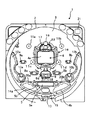
図1はパチンコ遊技機の遊技盤1を示す正面図であり、遊技盤1の前面の略円形領域にはガイドレール2で取り囲まれた遊技領域3が形成されている。
遊技領域3には、例えば、複数の図柄や数字等からなる識別情報(以下、特図という)を変動表示する可変表示装置4aを有する特別図柄表示装置4が備えられているほか、開閉扉5aにより開閉される大入賞口5bを有する特別変動入賞装置5、左右一対の開閉部材6aを有し特図始動口として機能する普通変動入賞装置6(いわゆる普電)、この普通変動入賞装置6の前面中央に位置して後述する普通図柄(以下、普図という)を表示する普通図柄表示器7、左右1個ずつのスルーチャッカー形式の普通図柄始動口8a、8b、左右2個ずつの一般入賞口9a、9b、10a、10b、風車と呼ばれる複数の打球方向変換部材11a〜11d、電飾用のサイドランプ12a、12b、アウト穴13、特別変動入賞装置5の両側や下側に設けられたランプ14a、14bおよび飾り15などが備えられている。
【0008】
可変表示装置4aの周囲を装飾してケーシングするセンターケース16の上部には4個の特図始動記憶表示器17が設けられており、普通変動入賞装置6の前面に位置する普通図柄表示器7の周囲には4個の普図始動記憶表示器18が設けられている。また、センターケース16の上端面中央位置には1個の一般入賞口19が設けられており、さらに、特別変動入賞装置5の両側上面にも左右1個ずつの一般入賞口20a、20bが設けられている。したがって、図示の遊技盤1の場合、特に限定しないが、独立した一般入賞口は、符号9a、9b、10a、10b、19、20a、20bで示すように、全部で7個設けられている。
特別図柄表示装置4の可変表示装置4aは、カラー画像(静止画や動画)の表示が可能な液晶ディスプレイ(LCD)であるが、これに限らず、例えば、他の平面形表示装置や冷陰極管型のディスプレイ(CRT)であってもよいし、あるいは、回胴式の機構を有する可変表示装置であってもよい。普通図柄表示器7は、例えば、一桁の数字を表示する7セグメントの表示部を有し液晶またはLED等よりなる表示器であり、この場合、上記普通図柄(普図)は一桁の数字である。特図始動記憶表示器17は特図の始動記憶の数を表示するものであり、同様に、普図始動記憶表示器18は普図の始動記憶の数を表示するものである。
【0009】
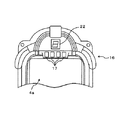
なお、遊技盤1の遊技領域3には、通常、天釘やヨロイ釘といった多数の障害釘が設けられるが、ここでは、図面の繁雑化を防ぐため一部を除いて省略している。また、同様に図示を略しているが、遊技盤1には、その他の各種装飾ランプやLED等が設けられていてもよい。例えば、本実施の形態の遊技盤1の場合、特に必須ではないが、右上隅に残賞球(賞球払い出し予定数と賞球払い出し実数の差)の有無を表示する残賞球有無表示器21(残賞球有無表示器21の代わりに残賞球の数を表示する残賞球数表示器を設けてもよく、あるいは、その両方を設けてもよい。)が設けられているほか、必須の要素として、センターケース16の上部に、確変判定図柄表示器兼ラウンド数表示器22(図2参照)が設けられている。なお、センターケース16は前記のとおり可変表示装置4aの周囲を装飾してケーシングするものであるから、センターケース16は発明の要旨に記載のケーシング部材に相当する。
この確変判定図柄表示器兼ラウンド数表示器22は、発明の要旨に記載の情報報知手段、遊技価値量情報報知手段、特殊遊技状態情報報知手段に相当し、その名前の意味するとおり、確変判定図柄(すなわち、特殊遊技状態か否かの図柄)を表示(報知)するとともに、大当たりのラウンド数も表示(報知)するものである。ラウンド数の報知は大当たりに伴う遊技価値の付与を終了する前に行われ、確変判定図柄の報知は同遊技価値の付与を終了する時に行われるようになっている。なお、上記報知の区別は、例えば、7セグメントの数字表示で行ってもよいし、表示色を異ならせることによって行ってもよいし、あるいは、キャラクタや記号等を表示することによって行ってもよい。
【0010】
また、本発明では、遊技盤1における遊技領域3の構成はどのようなものでもよく、特図の変動表示ゲームを行う遊技機であれば、任意の構成を取り得る。本形態例では、いわゆる「第1種」に属するタイプのものに適用した例を説明するが、「第1種」以外のタイプに属するパチンコ遊技機であってもよい。
【0011】
ここで、遊技盤1に設けられた、特別変動入賞装置5、普通変動入賞装置6および一般入賞口9a、9b、10a、10b、19、20a、20bは、これらの入賞口のいずれかに球が入賞すると、予め設定された数(15個を超えない数)の入賞球が払い出されるから、遊技球の獲得に直接的に関与する入賞口である。また、普通図柄始動口8a、8bはスルーチャッカー式の始動口であって、この始動口に遊技球が入賞(通過)すると、後述の普図変動ゲームを実行して普図当たり(例えば、普図が「7」で停止)となった場合に、上記入賞口の一つである普通変動入賞装置6の一対の開閉部材6aを逆ハの字に開いて普通変動入賞装置6への入賞を促すので、この普通図柄始動口8a、8bも入賞口である。したがって、本明細書では、遊技盤1に設けられた、特別変動入賞装置5、普通変動入賞装置6および一般入賞口9a、9b、10a、10b、19、20a、20bならびに普通図柄始動口8a、8bを総称する用語として適宜に「入賞口」を使用することにする。
【0012】
B.遊技機の裏機構
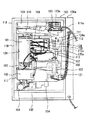
次に、図3はパチンコ遊技機(以下「遊技機100」という)の裏機構を示す図である。なお、図示の遊技機100はカード式の球貸機100aを併設するいわゆるCR機と称されるものであるが、これに限定されない。
図3において、遊技機100の裏機構に向かって左側には遊技制御装置101が設けられており、その下側には音制御装置102と排出制御装置103が設けられ、さらにその下側には発射ユニット104と発射制御装置105が設けられている。また、裏機構の中央部付近には装飾制御装置106と表示制御装置107が設けられており、その下側には電源供給ユニット108が設けられている。
遊技制御装置101は役物遊技に必要な各種制御を行うもので、中身が透けて見えるケース内にこの制御機能を実現するための制御基板が実装されている。音制御装置102は遊技状態に応じた各種の効果音を生成して遊技機100の前面等に配設されたスピーカ(図示略)から出力する制御を行うものであり、中身が透けて見えるケース内にこの制御機能を実現するための制御基板が実装されている。排出制御装置103は球の排出に必要な各種電気部品(例えば、後述の排出ユニット112の電気的駆動源)の制御を行うもので、中身が透けて見えるケース内にこの制御機能を実現するための制御基板が実装されている。
【0013】
発射ユニット104は遊技機100の前面下部に設けられた発射操作ノブ(不図示)の操作に応じて、球を発射するための機構である。発射制御装置105は球の発射に必要な各種電気部品(例えば、発射ユニット104の電気的駆動源)の制御を行うもので、中身が透けて見えるケースにこの制御機能を実現するための制御基板が実装されている。装飾制御装置106は遊技機100の前面等に配設された装飾用ランプ類の作動(点灯または消灯もしくは点滅)を制御するもので、中身が透けて見えるケース内にこの制御機能を実現するための制御基板が実装されている。
表示制御装置107は遊技制御装置101から出力される指令などに従ってセンター役物を制御し、センター役物の前面表示部(すなわち、特別図柄表示装置4の可変表示装置4a)に所定の画像を表示させるもので、中身が透けて見えるケース内にこの制御機能を実現するための制御基板が実装されている。電源供給ユニット108は遊技機100の外部からの電源(例えば、AC24V電源)を受けて、遊技機100の各部、例えば、遊技制御装置101、音制御装置102、排出制御装置103、発射ユニット104、発射制御装置105、装飾制御装置106および表示制御装置107などに必要な各種電源を発生して各々に供給する。
以上の各部、すなわち、遊技制御装置101、音制御装置102、排出制御装置103、発射ユニット104、発射制御装置105、装飾制御装置106、表示制御装置107および電源供給ユニット108などは、図面上にその一部を実体的に示すように、着脱可能な信号ケーブルや電源ケーブルによって接続されている。
【0014】
遊技機100の裏機構の上部付近から右側端部付近を経由して下部付近に至る経路上には、貯留タンク109、横方向の誘導路110、屈曲接続ユニット111、排出ユニット112、縦方向の誘導路113、入賞球集合棚(不図示)、入賞球流下樋(不図示)および球排出口114が順番に設けられている。入賞球集合棚と入賞球流下樋は部材の陰に隠れて見えない。
貯留タンク109は排出される前の球を予め貯留しておくもので、この貯留タンク109の球数不足は不図示の補給センサによって検出され、不足のときは島設備から球が補給されるようになっている。貯留タンク109に貯留された球は誘導路110と屈曲接続ユニット111によって排出ユニット112に導かれ、排出ユニット112は導かれた球を所定の球排出指令信号(排出制御装置103からの信号)に従って、遊技機100の前面に設けられた不図示の上皿へ所要数排出(ここでの排出は賞球排出と球貸し排出が含まれる)する。
【0015】
具体的には、排出ユニット112は例えば2条の排出通路を有し、各通路に設けられた不図示のソレノイド(後述の第1排出ソレノイド112a、第2排出ソレノイド112b;図5参照)を上記球排出指令信号に従って駆動して賞球用の球排出と球貸し用の球排出を行い、且つ、各通路から排出された排出球を不図示のセンサ(後述の第1排出センサ112c、第2排出センサ112d;図5参照)で検出して排出制御装置103に通知するとともに、さらに、賞球用の球排出数(賞球払い出し数)を専用のセンサ(以下「賞球払い出し数検出センサ112e」という)で検出して遊技制御装置101に通知する。
因みに、“賞球払い出し”とは遊技において発生した遊技価値を遊技者に提供するために行われる遊技球の排出のことをいう。
【0016】
遊技盤1の特別変動入賞装置5、普通変動入賞装置6および一般入賞口9a、9b、10a、10b、19、20a、20bに入った入賞球ならびにアウト穴13に入ったアウト球は、遊技盤1の裏面に設けられた不図示の入賞球集合棚に集められ、入賞球流下樋を介して球排出口114から島設備に戻されるようになっており、同様に、排出ユニット112の上流側に待機中の球も、遊技店の営業終了時等に不図示の球抜きソレノイド(図5の球抜きソレノイド173参照)を駆動することによって球排出口114から島設備に戻されるようになっている。
なお、排出ユニット112の上流側に待機中の球(一般に100個程度の球)が有るかどうかは、屈曲接続ユニット111の内部に設けられた半端センサ111a(予備球センサともいう)によって検出されるようになっている。
【0017】
117は基枠体である。この基枠体117は合成樹脂製の一体成型品で形成されており、遊技機100の前面枠118の裏側に固定された金属フレーム119に着脱可能に取り付けられている。そして、この基枠体117に上述の各構成部品のうちのいくつかの構成部品、すなわち、本実施の形態の場合、排出制御装置103、発射ユニット104、発射制御装置105、貯留タンク109、誘導路110、屈曲接続ユニット111、排出ユニット112、誘導路113、入賞球集合棚(不図示)、入賞球流下樋(不図示)および球排出口114などが着脱可能に取り付けられている。以下、基枠体117に取り付けられたこれらの構成部品のことを便宜的に「枠取り付け部品」ということにする。
金属フレーム119には遊技盤収納部120が形成されており、この遊技盤収納部120には遊技盤1(図1参照)が着脱可能に取り付けられている。そして、遊技盤1の裏側には上述の各構成部品のうち基枠体117に取り付けられた構成部品以外のもの、すなわち、本実施の形態の場合、遊技制御装置101、音制御装置102、装飾制御装置106、表示制御装置107および電源供給ユニット108などが着脱可能に取り付けられている。以下、以下、遊技盤1に取り付けられた構成部品のことを便宜的に「盤取り付け部品」ということにする。
【0018】
ここで、上述の「枠取り付け部品」と「盤取り付け部品」の例は、あくまでも一例にすぎない。「盤取り付け部品」は専ら遊技盤1の機種に依存する構成部品であればよく、「枠取り付け部品」はそれ以外の部品、すなわち、機種依存性のない部品(言い換えれば様々な機種の遊技盤1に共通に使用できる部品)であればよい。このような考え方に立って「枠取り付け部品」と「盤取り付け部品」を分類しておくことにより、図示の遊技機100にあっては、金属フレーム119の遊技盤収納部120から遊技盤1を取り外すことにより、その遊技盤1に取り付けられた「盤取り付け部品」、すなわち、遊技制御装置101、音制御装置102、装飾制御装置106、表示制御装置107および電源供給ユニット108などの構成部品を一緒に取り外すことができ、機種交換の容易化を図ることができる。
【0019】
ところで、枠取り付け部品や盤取り付け部品は、上記例示の構成部品のみに限らない。それ以外の部品も含まれている。例えば、枠取り付け部品には上記例示の構成部品のほかに、球貸し機接続ユニット121やセンサケーブル接続ユニット122および遊技店用第1ケーブル接続ユニット123などが含まれており、また、盤取り付け部品には上記例示の構成部品のほかに、遊技店用第2ケーブル接続ユニット124や検査用ケーブル接続ユニット125などが含まれている。
これらの接続ユニット121〜125は外部装置などからの信号ケーブルを接続するためのものであり、具体的には、球貸し機接続ユニット121は球貸機100aからの信号ケーブルを接続し、センサケーブル接続ユニット122は排出ユニット112の内部に設けられた賞球払い出し数検出センサ112eなどからの信号ケーブルを接続し、遊技店用第1ケーブル接続ユニット123および遊技店用第2ケーブル接続ユニット124は遊技店の管理用コンピュータからの信号ケーブルを接続し、さらに、検査用ケーブル接続ユニット125は第三者機関等の検査装置からの信号ケーブルを接続するためのものである。
これらの接続ユニット121〜125は接続相手のケーブルコネクタに合致した形状の受け側コネクタを備えており、例えば、遊技店用第1ケーブル接続ユニット123はコネクタ123aを介して遊技店の管理用コンピュータと遊技機100との間で所要の信号のやり取りを行うようになっている。
【0020】
遊技店用第1ケーブル接続ユニット123を介して遊技店の管理用コンピュータとの間でやり取りされる信号は「枠取り付け部品」の各々に必要な信号や「枠取り付け部品」の各々で発生した信号であり、例えば、発射制御装置105に対する発射停止信号(入力信号)、貯留タンク109の貯留球不足を示す球切れ信号(出力信号)、貸し出された遊技球の数を示す球貸し信号(出力信号)、払い出された遊技球の数を示す賞球数信号(出力信号)、遊技機100の金枠(ガラス枠)の開放を示す金枠開放信号(出力信号)などである。
一方、遊技店用第2ケーブル接続ユニット124もコネクタ124aを介して遊技店の管理用コンピュータと遊技機100との間で所要の信号のやり取りを行うようになっている。遊技店用第2ケーブル接続ユニット124を介して遊技店の管理用コンピュータとの間でやり取りされる信号は基本的に「盤取り付け部品」の一つである遊技制御装置101で発生したいくつかの信号であり、その信号の方向は遊技機100から管理用コンピュータへの方向(遊技機100から見て出力信号)である。この出力信号としては、例えば、特図の変動回数を示す図柄確定回数信号、大当たり中の状態を示す大当たり信号、大当たり中および普図・特図の高確率中を示す確率変動信号などが該当する。
【0021】
他方、検査用ケーブル接続ユニット125もコネクタ125aを介して第三者機関等の検査装置と遊技機100との間で所要の信号のやり取りを行うようになっている。検査用ケーブル接続ユニット125を介して検査装置との間でやり取りされる信号は基本的に「盤取り付け部品」の一つである遊技制御装置101で発生したいくつかの信号(特に検査に必要な信号)であり、その信号の方向は遊技機100から検査装置の方向(遊技機100から見て出力信号)である。この出力信号としては、例えば、各入賞口への遊技球の入賞を示す信号、発射球の検出信号、賞球の払い出し信号などが該当する。
【0022】
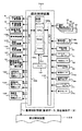
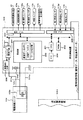
C.制御系統
図4および図5は遊技機100における制御系統を示す図である。図4において、遊技制御装置101はパチンコ遊技等に必要な役物制御を行うワンチップマイコンからなる遊技用演算処理装置(遊技用マイクロコンピュータ)160と、高精度発振器(例えば、クリスタル発振器)の発振周波数を分周して所定のクロックを得るクロック生成回路(CLK)161と、各種センサ信号を受け入れる入力インターフェース162と、出力インターフェース163とを含んで構成される。
発明の要旨に記載の情報報知手段、特別遊技価値決定用乱数取得手段、特殊遊技状態決定手段、遊技価値量決定手段、遊技価値量情報報知手段、特殊遊技状態情報報知手段として機能する遊技用演算処理装置160は、後述の遊技制御プログラムを実行するCPU160a、同プログラムを格納するROM160bおよび作業用メモリ(RAM160c)などをワンチップ化して内蔵しており、いわゆるアミューズチップ用のICとして製造されている。
【0023】
入力インターフェース162には、遊技盤1に設けられた各センサ、すなわち、7個の入賞球検出センサ31〜37、2個の普図始動ゲートセンサ38、39、1個の特図始動センサ40、1個のカウントセンサ41、1個の継続センサ42および1個の発射球検出センサ43からの各検出信号が入力されるとともに、半端センサ111a、賞球払い出し数検出センサ112e、オーバフローセンサ171および金枠センサ172からの各検出信号が入力される。ここで、既述のとおり、半端センサ111aは排出ユニット112の上流側に待機中の球が有るかどうかを検出するものであり、また、賞球払い出し数検出センサ112eは排出ユニット112から実際に(遊技者に)払い出された賞球数を検出するものである。さらに、オーバフローセンサ171は遊技機100の前面の下皿の満杯状態を検出するものであり、金枠センサ172は遊技機100の前面の金枠(遊技盤1の前面を覆うガラス枠)の開閉を検出するものである。
なお、オーバフローセンサ171および金枠センサ172の取り付け位置については図示しないが、上記の検出機能を実現するための適当な位置であればよく、例えば、オーバフローセンサ171を上皿と下皿の間の球移動通路に設けてもよく、また、金枠センサ172を金枠の開閉部材の近くに設けてもよい。
【0024】
出力インターフェース163からは、遊技盤1に設けられた各入賞口のうち駆動源を有するもの、すなわち、特別変動入賞装置5や普通変動入賞装置6の各駆動源(不図示の大入賞口ソレノイドや普通電動役物ソレノイド)を駆動するための駆動信号が出力されるとともに、普通図柄表示器7に普通図柄を表示するための表示信号が出力され、さらに、遊技機100の裏機構に設けられた各装置、すなわち、音制御装置102、排出制御装置103、発射制御装置105、装飾制御装置106および表示制御装置107へ所要の制御信号(または制御情報;例えば、排出制御装置103に対しては賞球データや排出条件データを含む賞球制御情報)が出力されるほか、確変判定図柄表示器兼ラウンド数表示器22に対して表示信号が出力され、さらに、遊技店用第1ケーブル接続ユニット123、遊技店用第2ケーブル接続ユニット124および検査用ケーブル接続ユニット125の各々に対して所要の外部出力信号が出力される。
【0025】
排出制御装置103は、図5に示すように、CPU201、ROM202、RAM203、所定のクロックを得るクロック生成回路(CLK)204、入力インターフェース205、出力インターフェース206、ロジック電源回路207、停電検出回路208、逆流防止用のダイオード209を含んで構成されている。
CPU201は遊技球の排出(賞球排出および貸球排出を含む)に必要な処理を行い、ROM202は排出制御に必要なプログラム等を格納し、RAM203はワークメモリとして使用される。なお、RAM203は遊技価値情報を格納する賞球データメモリエリア、各種データを格納する各種データメモリエリアおよびその他のワークメモリエリア等に分けられており、そのうちの賞球データメモリエリアをバッテリバックアップできるようになっている。電源ユニット108に設けられたコンデンサ(電池でもよい)108aおよび排出制御装置103のダイオード209はそのためのバッテリバックアップ手段を構成する。
【0026】
入力インターフェース205には、遊技制御装置101からの賞球制御情報(賞球データや排出条件データなど)が入力されるとともに、前述の第1排出センサ112cおよび第2排出センサ112dからの検出信号が入力され、さらに、球抜きセンサ174(営業終了時等に行われる排出ユニット112から島設備への球抜きを検出するためのセンサ)からの検出信号が入力されている。また、出力インターフェース206からは、球抜きソレノイド173へ駆動信号が出力されるとともに、上述の第1排出ソレノイド112a、第2排出ソレノイド112bへ駆動信号が出力され、さらに、残賞球の有無を表示する残賞球有無表示器21と残賞球の数を表示する残賞球数表示器21aへ表示信号が出力されており、且つ、残賞球報知信号出力端子175を介して外部装置(例えば、遊技店の管理用コンピュータ)へ残賞球情報(残賞球の有無や残賞球の数)が出力されている。
排出制御装置103は遊技制御装置101から送信された賞球制御情報のうちの賞球データをRAM203の賞球データメモリエリアに順次加算記憶するとともに、その賞球データメモリエリアの加算記憶と排出条件データとに基づいて所要の排出処理を行う。
【0027】
ロジック電源回路207には電源供給ユニット108からDC12Vが供給されており、ロジック電源回路207はDC12VをDC5Vに変換して上記CPU201、ROM202、RAM203等の各素子の動作に必要な電源を供給する。RAM203には不可逆素子として機能するダイオード209を介してロジック電源回路207からDC5Vが供給される。また、電源供給ユニット108からのDC5Vは配線211a、211bを通して電源供給ユニット108の内部に配置されたコンデンサ108aにも供給されるようになっている。コンデンサ108aは単に電源供給ユニット108の基板上に配置されているだけで(あるいは基板上でなく別体でもよい)、電源の供給は排出制御装置103側のロジック電源回路207から受けている。配線211a、211bの途中にはオス/メスタイプのコネクタ(図示略)が設けられており、コネクタにより配線211a、211bは電源供給ユニット108側と排出制御装置103側との間で分離可能になっている。
【0028】
RAM203とコンデンサ108aの接続状態を説明すると、RAM203の電源端子は排出制御装置103内で生成されたロジック電圧をダイオード209を介して受けるように接続され、この電源端子は更に電源供給ユニット108に配置したコンデンサ108aのプラスの電位に接続されている。一方、コンデンサ108aは排出制御装置103のロジック電源回路207が生成したロジック電圧であるDC5Vの供給を受けて充電状態に維持されるとともに、コンデンサ108aのグランドレベルは配線211bを介して排出制御装置103のグランドに導通するようになっている。したがって、排出制御装置103内で生成されたロジック電源は、RAM203の電源端子にダイオード209を介して供給されてRAM203の作動を可能にするとともに、コンデンサ108aも充電するようになっている。なお、ダイオード209を介してコンデンサ108aを充電しているので、停電時はRAM203(厳密にはRM203の第2エリア203bと第3エリア203c)のみをバックアップする構成になっており、他の回路にはコンデンサ108aの電圧は供給されない。
停電検出回路208は電源供給ユニット108からロジック電源回路207への電源供給が断たれたことを検出(例えば、DC12Vが所定の電圧まで低下したとき停電として検出)するもので、停電になると、CPU201に強制的に割り込みをかけてCPU201を停止させる。
【0029】
次に、作用を説明する。
まず、本例の遊技機100で行われる遊技の概要について説明する。
ガイドレール2を介して遊技領域3に打込まれた遊技球が、特図始動口を兼ねる普通変動入賞装置6に入賞すると、可変表示装置4aの複数の変動表示領域(例えば上下または左右の3箇所)において多数の特図(数字、文字、記号、模様等よりなるもの)が変動(例えば、スクロール)する表示(いわゆる変動表示)が行われて、変動表示ゲームが行われる。そして、この変動表示ゲームの結果(停止した特図の組合せ)が特定表示結果(例えば、「777」などのゾロ目)であれば、大当りと呼ばれる遊技価値が付与される。
なお、制御上は、例えば、特図始動口への遊技球の入賞があったことを条件(始動条件)として、大当り判定用の乱数値(遊技価値判定用乱数値)などの各種乱数値が抽出記憶され、この抽出記憶された乱数値と予め設定された判定値とが判定時に比較判定され、この比較判定結果に基づいて、予め停止図柄(大当りとするか否か)やリーチアクションを行うか否かなどが決定され、この決定に応じて上記変動表示が開始される。
【0030】
また、いわゆる確率変動の制御によって大当りの確率が高確率(いわゆる確変状態)に設定されている場合は、通常よりも大当りとなる確率が増加するようになっており、この確変状態の設定も、所定の乱数値(特殊遊技状態判定用乱数値)を抽出して判定することによって行っている。さらに、大当たりのラウンド数の設定も、所定の乱数値(遊技価値量決定用乱数値)を抽出して判定することによって行っている。
【0031】
大当りになると、特別変動入賞装置5の開閉扉5aが規定時間(例えば、30秒)を越えない範囲内において、例えば10個入賞までの期間だけ一時的に開放する開放動作が行われる。そして、この開放動作は、継続入賞球の検出(継続センサ42による入賞球の検出)が行われることを条件に、nラウンドを上限にして繰り返し行われるようになっており、そのnの値は、後で詳述するが、上記特殊遊技状態判定用乱数値の判定結果と、上記遊技価値量決定用乱数値の判定結果とに応じて決定されるようになっている。
また、上記特図の変動表示ゲーム中または大当り中に、普通変動入賞装置6にさらに遊技球が入賞したときには、遊技制御装置101の内部(の例えばRAM160c)にその入賞数が特図始動記憶(この場合最大4個まで)として記憶され、変動表示ゲームまたは大当りが終了した後に、その特図始動記憶に基づいて上記特図の変動表示ゲームが繰り返し実行されるようになっている。因みに、特図記憶の記憶数は、特図始動記憶表示器17に表示されるようになっている。
【0032】
一方、遊技中に、遊技球が普通図柄始動口8a、8bに入賞(通過)したときは、普通図柄表示器7の普図(この場合、一桁の数字)の変動表示による普図の変動表示ゲームが行われる。そして、この変動表示ゲーム結果(停止した普図)が所定の態様(例えば、「7」)であれば、普図当りと呼ばれる遊技価値が付与される。
この普図当りの状態になると、普通変動入賞装置6の一対の開閉部材6aが逆ハの字に開いた開放状態に、例えば0.5秒程度保持される遊技が行われる。これにより、普通変動入賞装置6に遊技球が入賞し易くなり、その分、特図の変動表示ゲームの実施回数が増えて大当りになる可能性が増す。
また、上記普図の変動表示ゲーム中に、普通図柄始動口8a、8bにさらに遊技球が入賞したときには、普図始動記憶表示器18が点灯してこの場合4個まで記憶され、普図の変動表示ゲームの終了後に、その記憶に基づいて上記普図の変動表示ゲームが繰り返される。
【0033】
D.制御系の動作
次に、前述した制御系により行われる本例の遊技機100の制御について説明する。
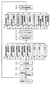
(a)遊技制御プログラム
図6は、遊技制御装置101の遊技用演算処理装置(遊技用マイクロコンピュータ)160で実行される遊技プログラムのフローチャートを示す図である。この制御処理は、所定の基準時間(例えば、2ms)毎に1シーケンスずつ行われる。すなわち、最終ステップS23の残余時間処理において、CLK161から遊技用マイクロコンピュータ160に上記基準時間間隔の周期信号に相当するリセット信号が入力するたびに、ステップS1から繰り返し実行される。
処理が開始されると、まず、ステップS1において電源の投入時であるか否かを判定する電源投入判定処理を行い、電源投入時であれば初期化処理を行って、ROM160bの正常判定処理やRAM160cにおけるワークエリアのイニシャライズ、I/Oレジスタの設定、システム内部のレジスタの設定処理およびフラグのイニシャライズ等が行われる。また、電源投入時でなければ、ステップS2に進んで入力処理を行い、入力インターフェース回路162からの信号を取り込む。これにより、外部の入力情報が取得される。次いで、ステップS3で出力処理を行い、出力インターフェース回路163に制御信号を出力する。これにより、出力インターフェース回路163に接続される遊技盤1上の各器具が駆動され、例えば、特別変動入賞装置5の駆動等が行われる。
【0034】
次いで、ステップS4〜S11のうちの一つの処理を時分割で順次行う。ステップS4〜S11の概要は以下のとおりである。
<ステップS4:排出制御情報編集処理>
ステップS4の排出制御情報編集処理では、遊技用マイクロコンピュータ160から排出制御装置103へ送信する賞球数制御情報、賞球数データ等に関する編集が行われる。
<ステップS5:排出制御装置通信処理>
ステップS5の排出制御装置通信処理では、遊技用マイクロコンピュータ160から排出制御装置103へ賞球数制御情報等を送信する。
<ステップS6:音声制御装置通信処理>
ステップS6の音声制御装置通信処理では、遊技用マイクロコンピュータ160から音制御装置102へ音声制御信号(例えば、遊技ゲームの効果音の制御信号)を送信する。
<ステップS7:装飾制御装置通信処理>
ステップS7の装飾制御装置通信処理では、遊技用マイクロコンピュータ160から装飾表示制御装置106へ装飾制御信号を送信する。これにより、遊技盤1の各種装飾ランプやLED等を装飾発光させて遊技を演出することが行われる。
【0035】
<ステップS8:表示制御装置通信処理>
ステップS8の表示制御装置通信処理では、後述する表示制御装置送信情報編集処理S20で行われる送信情報の設定に基づいて、実際に表示制御装置107に対して所定の表示制御信号が出力される(つまり、送信領域にセットされているコマンドデータが送信される)。これにより、特別図柄表示装置4の可変表示装置4aにて複数の特図が複数列で変動表示等され、変動表示ゲームが行われる。
<ステップS9〜ステップS11:スルー処理>
ステップS9〜ステップS11のスルー処理では、何も処理を行わずに、これらのステップをスルーする。
【0036】
次に、図示の遊技プログラムでは、以上の時分割処理がなされた後に、ステップS12で乱数生成処理を行う。乱数生成処理では、特図に関連する乱数や普図に関連する乱数の更新が行われる。特図に関連する乱数としては、例えば、大当り乱数(大当りとするか否かを決定するための乱数)、リーチ乱数(リーチ態様決定用の乱数)、大当り停止図柄乱数(大当り停止図柄決定用の乱数)、確率変動乱数(高確率の大当たりとするか否かを決定するための乱数)、ラウンド数決定乱数(ラウンド数を16Rにするか10Rにするかを決定するための乱数)などがある。乱数の生成では、各乱数の基数を例えば「1」ずつインクリメントして更新することが行われる。したがって、本ルーチンが繰り返される毎に、各乱数の発生条件(基数)が変化し、大当り或いは普図当りの乱数抽出値がアトランダム性を保つようになる。他の乱数についても同様である。
【0037】
次いで、ステップS13でセンサ入力処理を行う。ここでは、入賞球検出センサ31〜37、普図始動ゲートセンサ38、39、特図始動センサ40、カウントセンサ41、継続センサ42、半端センサ111a、賞球払い出し数検出センサ112e、オーバフローセンサ171および金枠センサ172などからの入力監視を行うとともに、これらセンサからの入力信号に基づいて、特図変動や普図変動の始動記憶(特図始動記憶および普図始動記憶)の更新、特図や普図などに関連する乱数の抽出、賞球数記憶、大当り時のラウンド継続の設定、などの処理を行う。なお、このセンサ入力処理における各処理のうち特図始動センサ40に関するサブルーチン(特図始動センサ監視処理)については、図7により後述する。
【0038】
次いで、ステップS14〜S21のうちの一つの処理を時分割で順次行う。ステップS14〜S21の概要は以下のとおりである。
<ステップS14:特別図柄ゲーム処理>
ステップS14の特別図柄ゲーム処理では、特図をスクロールさせる前の始動記憶監視、図柄停止監視および大当り処理の何れかに対応した処理が行われる。なお、この特別図柄ゲーム処理については、概略を後述する。
<ステップS15:普通図柄ゲーム処理>
ステップS15の普通図柄ゲーム処理では、遊技球が普通図柄始動口8a、8bに入賞(通過)したときに、普通図柄表示器7の普図(この場合、一桁の数字)の変動表示による変動表示ゲームについての処理を行い、普図当りとなった場合には対応する普図当り処理を行う。
<ステップS16:図柄変動処理>
ステップS16の図柄変動処理では、特図を変動表示(例えば、スクロール)させる処理が行われ、所定時間経過後に、図柄変動が停止して大当り或いは外れの何れかになる。
【0039】
<ステップS17:装飾制御情報編集処理>
ステップS17の装飾制御情報編集処理では、遊技用マイクロコンピュータ160から装飾表示制御装置106へ送信する装飾制御情報の編集(例えば、サイドランプ12a、12b、14a、12b等の装飾をどのようにするかの編集)を行う。
<ステップS18:ソレノイド編集処理>
ステップS18のソレノイド編集処理では、遊技用マイクロコンピュータ160から、特別変動入賞装置5(の大入賞口ソレノイド)や普通変動入賞装置6(の普通電動役物ソレノイド)へ送信するソレノイド制御情報の編集を行う。
<ステップS19:不正監視処理>
ステップS19の不正監視処理では、特別変動入賞装置5に対するノーカウントの監視、その他の不正監視が行われ、不正等の場合には、例えば後述のステップS21の外部端子情報編集処理にてエラー信号を外部の管理装置に出力するような編集が行われる。
【0040】
<ステップS20:表示制御装置送信情報編集処理>
ステップS20の表示制御装置送信情報編集処理では、遊技用マイクロコンピュータ160から表示制御装置107へ送信する表示制御情報(コマンドデータよりなる表示制御信号)の編集を行う(つまり、コマンドデータを選択して送信領域にセットする)。
<ステップS21:外部端子情報編集処理>
ステップS21の外部端子情報編集処理では、遊技用マイクロコンピュータ160から遊技店用第1ケーブル接続ユニット123や遊技店用第2ケーブル接続ユニット124を介して管理用コンピュータ等へ送信する遊技店用外部端子情報の編集を行うとともに、検査用ケーブル接続ユニット125を介して第三者機関等の検査装置へ送信する検査用外部端子情報の編集を行う。
【0041】
そして、本遊技プログラムでは、以上の時分割処理がなされた後に、残余時間処理(S22)を行い、上記基準時間(例えば、2ms)になるまで待機して、残余時間がゼロになったときに1シーケンスを終了し、再び、ステップS1からのシーケンスを開始する。
【0042】
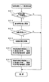
(b)特図始動センサ監視処理
図7は上記遊技プログラムのセンサ入力処理(S13)で実行される特図始動センサ40に関するサブルーチン(特図始動センサ監視処理)を示すフローチャートである。このフローチャートを開始すると、まず、ステップS31で特図始動センサ40からの特図始動信号の有無を判定する。すなわち、普通変動入賞装置6への始動入賞を判定する。そして、入賞球がなければ、そのままフローチャートを終了して遊技プログラム(のセンサ入力処理S13)に復帰し、入賞球があれば、ステップS32で賞球用記憶を+1して更新する。次に、ステップS33で賞球用記憶の更新値が始動記憶の最大値(一般に4個;以下同様とする)以下であるか否かを判定し、以下でなければ、そのままフローチャートを終了して遊技プログラム(のセンサ入力処理S13)に復帰する一方、以下であれば、ステップS35およびステップS36を実行した後、フローチャートを終了して遊技プログラム(のセンサ入力処理S13)に復帰する。
【0043】
ステップS35では、特図乱数記憶領域(遊技価値判定用乱数値の記憶領域)より乱数値を取得(抽出)し、特図判定用記憶領域に記憶する。また、ステップS36では、確変乱数記憶領域(特殊遊技状態判定用乱数値の記憶領域)より乱数値を取得(抽出)し、確変判定用記憶領域に記憶する。ここで、上記四つの領域(特図乱数記憶領域、確変乱数記憶領域、特図判定用記憶領域および確変判定用記憶領域)は、いずれもRAM160cのワークエリア上に確保された領域であるが、前二つの領域(特図判定用記憶領域と確変乱数記憶領域)は、特図乱数に使用する数列(例えば、0〜299)と確率変動乱数に使用する数列(例えば、0〜9)を記憶するために使用され、後二つの領域(特図判定用記憶領域と確変判定用記憶領域)は、各数列から抽出された一つの乱数値を記憶するために使用される。
したがって、例えば、ステップS35で特図乱数記憶領域から乱数値x(x:上記例示に従えば0〜299の間の任意の値)が抽出されたとすると、この乱数値xは特図判定用記憶領域に記憶され、同様に、ステップS36で確変乱数記憶領域から乱数値y(y:上記例示に従えば0〜9の間の任意の値)が抽出されたとすると、この乱数値yは確変判定用記憶領域に記憶される。
【0044】
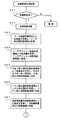
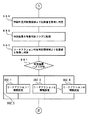
(c)特別図柄ゲーム処理
図8は上記遊技プログラムの特別図柄ゲーム処理(S14)の要部フローチャートである。このフローチャートが開始されると、まず、ステップS15aの分岐処理で処理番号により分岐する。この分岐処理は、以下の各処理過程(ステップS15b、S15c、S15d、……)ごとに定められている処理NO.(処理番号)に従って、以下の各処理のうち該当するいずれか一つのを行うための判断処理である。
<始動記憶監視処理:処理No.1>
ステップS15bの始動記憶監視処理では、特図始動記憶を監視し、特図の停止図柄(大当り、外れ図柄等)を決定するとともに、リーチアクションの情報設定や特殊遊技状態の発生/非発生の設定ならびに大当たりラウンド数(16R、10R)の設定などが行われる。なお、ここで設定された情報は、遊技プログラムの表示制御装置送信情報編集処理(S20)で使用され、ここでの設定に対応した表示制御信号が適宜出力されることで、ここでの設定どおりに特図の変動表示ゲームでの表示(例えば、リーチアクションや停止図柄の表示)が行われる。この始動記憶監視処理については、図9〜図13により詳細を後述する。
<図柄停止監視処理:処理No.2>
ステップS15cの図柄停止監視処理では、特図の図柄変動が終了して停止したかどうかを監視し、次の処理(大当り処理、始動記憶監視処理)に処理番号を格納する。
<大当り処理:処理No.3>
ステップS15dの大当り処理では、特図の図柄変動が終了して大当りで停止したとき、大当りに対応する処理を行い、次の処理(始動記憶監視処理)に処理番号を格納する。
【0045】
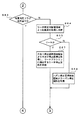
(d)始動記憶監視処理
図9〜図13は特別図柄ゲーム処理における始動記憶監視処理のフローチャートである。このフローチャートを開始すると、まずステップS51で特図始動記憶があるか否かを判別し、特図始動記憶がなければリターンする。特図始動記憶があると、ステップS52に進んで特図始動記憶を減算(すなわち、特図始動記憶を「−1」だけ更新)する。これにより、特図始動記憶表示器17に表示される特図始動記憶数が1つだけ少なくなり、遊技者に特図の始動入賞が減算されたことが報知される。
【0046】
次に、ステップS53でリーチ乱数記憶領域より乱数値(すなわち、リーチ乱数)を取得し、始動記憶に対応したリーチ乱数判定用領域に記憶する。これにより、変動開始フェッチによってリーチ乱数の抽出が行われて格納され、格納されたリーチ乱数は後述のステップS64でリーチを行うか否かの判定に使用されることになる。
次いで、ステップS54でリーチアクション乱数記憶領域より乱数値(すなわち、リーチアクション乱数)を取得し、始動記憶に対応したリーチアクション乱数判定用領域に記憶する。これにより、同様に変動開始フェッチによってリーチアクション乱数の抽出が行われて格納され、格納されたリーチアクション乱数は後述のステップS60でリーチアクションの種類や内容の判定に使用されることになる。
【0047】
次に、ステップS55で大当り停止図柄乱数記憶領域より乱数値(すなわち、大当り停止図柄乱数)を取得し、始動記憶に対応した大当り停止図柄乱数記憶領域に記憶する。これにより、いわゆる変動開始フェッチによって大当り停止図柄乱数の抽出が行われて格納され、格納された大当り停止図柄乱数は後述のステップS67およびステップS75で大当り停止図柄の指定に使用されることになる。
次いで、ステップS56でハズレ停止図柄乱数記憶領域より乱数値(すなわち、ハズレ停止図柄乱数)を取得し、始動記憶に対応したハズレ停止図柄乱数記憶領域に記憶する。これにより、いわゆる変動開始フェッチによってハズレ停止図柄乱数の抽出が行われて格納され、格納されたハズレ停止図柄乱数は後述のステップS66でハズレ停止図柄の指定に使用されることになる。
【0048】
次いで、ステップS57で遊技価値量乱数記憶領域より乱数値(すなわち、ラウンド数を16Rにするか10Rにするかを決定する乱数)を取得し、遊技価値量決定用記憶領域に記憶する。これにより、いわゆる変動開始フェッチによってラウンド数決定用乱数の抽出が行われて格納され、格納されたラウンド数決定用乱数は、後述のステップS72において、特殊遊技フラグの内容を踏まえたラウンド数の指定に使用されることになる。
次いで、ステップS58で特図判定用記憶領域より該当する乱数値(該当する乱数値とは、変動開始フェッチのタイミングで取得され記憶されている乱数のうち最も古い乱数値のこと)を取得し、取得した乱数値(前記乱数値x)と予め設定されている所定値(大当たりを決定する判定値)とを比較判定した後、ステップS59で比較判定結果(大当たりか否か)を特賞判定フラグに記憶する。
なお、本実施例では、入賞フェッチおよび変動開始フェッチによって、各種乱数を抽出しているが、これに限らず、例えば、すべてを入賞フェッチで抽出したり、または、その他のタイミングで抽出したりしてもよい。
【0049】
ここで、上記大当たりを決定する判定値をXとすると、このXの値は、例えば、通常の大当たり確率を1/300とした場合、0〜299の数列の中から予め選択された一つの数、例えば、X=0とすることにより、乱数値xが0となる確率、すなわち、通常の大当たり確率を1/300とすることができる。一方、確変当たりの確率を通常の大当たり確率の、例えば、n倍とするならば、前記Xの種類をn種類として、X=0、1、2、3、4とすることにより、乱数値xが0、1、2、3または4のいずれかと一致した場合に大当たりを発生することができ、通常の大当たり確率のn倍の確変状態(特殊遊技状態)にすることができる。
【0050】
次いで、ステップS60でリーチアクション判定用記憶領域より該当する乱数値(すなわち、リーチアクション乱数)を取得し、取得した乱数値と予め設定されている所定値(リーチアクションを決定する判定値)とを比較判定する。次いで、ステップS61で、ステップS59の比較判定結果に基づく分岐処理を行い、ステップS62_1のリーチアクション1情報設定、ステップ62_2のリーチアクション2情報設定、……、ステップS62_NのリーチアクションN情報設定の何れかの設定処理を実行する。ステップS62_0は情報の設定を行わないパススルーである。
なお、リーチアクション1情報〜リーチアクションN情報は、異なる態様の各種リーチアクションの情報であり、これに基づいて様々なリーチアクションの演出が可能となる。そして、大当たりの場合および後述のステップS65でリーチ発生と判定された場合に、取得したリーチアクション乱数に対応したリーチアクション1〜リーチアクションNのうちの一つのリーチアクション演出が、特別図柄表示装置4の可変表示装置4aによって行われる。
【0051】
次いで、ステップS63で、上記記憶された特賞判定フラグが大当りか否かを判別し、大当りであればステップS70(図13)に分岐し、大当りでなければステップS64に分岐する。
ステップS64では、リーチ乱数判定用記憶領域より該当する乱数値(すなわち、リーチ乱数)を取得し、取得した乱数値と予め設定されている所定値(リーチするか否かを決定する判定値)とを比較判定する。
【0052】
次いで、ステップS65では、ステップS64の比較判定結果によりリーチするか(リーチ発生か)否かを判別する。リーチ発生でなければ、ステップS66でハズレ停止図柄を作成してステップS68(図12)に進み、リーチ発生であれば、ステップS67で大当たり停止図柄格納領域より大当たり停止図柄を取得し、リーチアクションに適合するリーチ停止図柄を作成してステップS68(図12)に進む。これにより、リーチ発生の場合は、ステップS67で作成されたリーチ停止図柄により、ステップS62_1〜ステップS62_Nの何れかで設定されたリーチアクションに対応してリーチ演出が行われることになる。そして、リーチ発生または非発生のいずれの場合も、ステップS68において、決定した停止図柄のデータを停止図柄格納領域に記憶した後、ステップS69で処理番号(処理No.)を1(次の図柄停止監視処理)に設定し、特別図柄ゲーム処理にリターンする。
【0053】
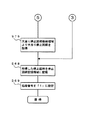
一方、ステップS63で特賞フラグの大当たりが判定された場合は、図13のステップS70に進み、確変判定用記憶領域から乱数値(すなわち、特殊遊技状態を発生するか否かの乱数値)を取得し、あらかじめ設定された所定値(特殊遊技状態を発生させるための乱数値)と比較判定して、ステップS71でその判定結果を特殊遊技判定フラグに記憶する。次いで、ステップS72で遊技価値量決定用記憶領域から乱数値(すなわち、ラウンド数を16Rにするか10Rにするかを決定するための乱数値)を取得し、あらかじめ設定された各ラウンド数ごとの所定値(詳細は後述)と比較判定して、ステップS73でその判定結果と上記特殊遊技フラグの内容を踏まえて、以下に説明するステップS74の四つのモードの分岐処理を選択し、ステップS75(図12)で大当たり停止図柄格納領域より大当たり停止図柄を取得し、ステップS68で停止図柄のデータを停止図柄格納領域に記憶した後、ステップS69で処理番号(処理No.)を1(次の図柄停止監視処理)に設定し、特別図柄ゲーム処理にリターンする。
【0054】
<モードA:ステップS74a>
非特殊遊技状態で、且つ、ラウンド数を16Rとするモードである。このモードを選択した場合は、次回の大当たりの可能性が低い特図低確率状態に設定されるとともに、ラウンド数が16Rに設定される。
<モードB:ステップS74b>
非特殊遊技状態で、且つ、ラウンド数を10Rとするモードである。このモードを選択した場合は、次回の大当たりの可能性が低い特図低確率状態に設定されるとともに、ラウンド数が10Rに設定される。
<モードC:ステップS74c>
特殊遊技状態で、且つ、ラウンド数を16Rとするモードである。このモードを選択した場合は、次回の大当たりの可能性が高い特図高確率状態に設定されるとともに、ラウンド数が16Rに設定される。
<モードD:ステップS74d>
特殊遊技状態で、且つ、ラウンド数を10Rとするモードである。このモードを選択した場合は、次回の大当たりの可能性が高い特図高確率状態に設定されるとともに、ラウンド数が10Rに設定される。
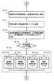
【0055】
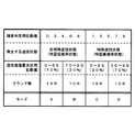
図14は上記四つのモードの選択条件を示す図である。この図において、モードAとモードBは、確変判定用乱数値が0,2,4,6,8のいずれかに一致した場合(特図低確率状態)に選択され、また、モードCとモードDは、確変判定用乱数値が1,3,5,7,9のいずれかに一致した場合(特図高確率状態)に選択されることを表している。そして、モードAは、遊技価値量決定用乱数値が0〜69のいずれかに一致した場合に選択され、モードBは、遊技価値量決定用乱数値が70〜99のいずれかに一致した場合に選択されることを表している。さらに、モードCは、遊技価値量決定用乱数値が0〜29のいずれかに一致した場合に選択され、モードDは、遊技価値量決定用乱数値が30〜99のいずれかに一致した場合に選択されることを表している。
【0056】
この選択条件において、特図低確率状態のモード(モードA、B)と特図高確率状態のモード(モードC、D)は各々50%の割合で発生するようになっているのに対して、それぞれの確率状態における16Rと10Rのモードの割合は異なっている。すなわち、特図低確率状態のモードA(16R)は70%、モードB(10R)は30%の割合で発生するようになっており、且つ、特図高確率状態のモードC(16R)は30%、モードD(10R)は70%の割合で発生するようになっている。このような選択条件によれば、特図高確率状態と特図低確率状態の発生割合を50%にすることができるとともに、特図高確率状態のときのラウンド数の設定割合を少ない方(10R)に偏らせることができ、且つ、特図低確率状態のときのラウンド数の設定割合を多い方(16R)に偏らせることができる。したがって、確変選択とラウンド数選択の柔軟な組み合わせを得ることができる。
上記四つのモードの選択結果の情報は、既述のとおり、遊技盤1に設けられた確変判定図柄表示器兼ラウンド数表示器22で報知されるようになっており、特に、同情報のうちのラウンド数の情報は大当たりに伴う遊技価値の付与終了前に、そして、同情報のうちの特殊遊技状態の発生/非発生の情報は同遊技価値の付与終了時に報知されるようになっている。
【0057】
次に、本実施の形態における各種報知タイミングについて説明する。
図14に示したとおり、本実施の形態における大当たり時の変動表示ゲームは、モードA〜モードDのいずれかのモードに従って行われる。非特殊遊技状態(特図低確率状態)の大当たりはモードAとモードBの二つであり、これらのモード(A,B)の判定条件は確変判定用乱数値が偶数(0,2,4,6,8のいずれか)の場合である。また、特殊遊技状態(特図高確率状態)の大当たりはモードCとモードDの二つであり、これらのモード(C,D)の判定条件は確変判定用乱数値が奇数(1,3,5,7,9のいずれか)の場合である。
一方、大当たり時のラウンド数が10回(少ない遊技価値量)になるか16回(多い遊技価値量)になるかは遊技価値量決定用乱数値によって判定され、例えば、非特殊遊技状態では70%の確率で16R(モードA)、残り30%の確率で10R(モードB)となり、特殊遊技状態では30%の確率で16R(モードC)、残り70%の確率で10R(モードD)となる。
【0058】
本実施の形態では、遊技盤1のセンターケース16に設けられた表示器(確変判定図柄表示器兼ラウンド数表示器22)によって、非特殊遊技状態と特殊遊技状態の報知およびラウンド数の報知を行なうが、その報知タイミングは非特殊遊技状態と特殊遊技状態の報知については遊技価値の付与状態が終了する場合、ラウンド数の報知については遊技価値の付与状態が終了する前である。
【0059】
ここで、遊技価値の付与状態が終了する場合とは、大当たりの最終ラウンド終了時(より詳細には遊技価値の付与が終了して特別変動入賞装置5の大入賞口5bが閉じるとき)、最終ラウンドの終了直後、最終ラウンドの実行中(まだ大入賞口5bが閉じていない)、または、最終ラウンドの終了から次回の変動表示ゲームが開始されるまでの間の任意時点、のいずれかである。これらのいずれかでは、多くの遊技者は遊技価値の付与が終わったことを悟り、大当たりに伴う興奮を急速に冷ますことになるが、上記の場合(遊技価値の付与状態が終了する場合)に、大当たり後の遊技状態が特殊遊技状態になるか否かのゲームを開始することにより、再び期待感を持たせて興奮の持続を誘うことができるからである。
【0060】
また、遊技価値の付与状態が終了する前とは、遊技価値の付与が開始されてから終了するまでの間の任意時点であり、例えば、大当たりに伴う大入賞口5bの1ラウンドの開動作スタートから最終ラウンドの開動作終了までの任意時点であるが、ラウンド数の報知は、そもそもその時点で実行中のラウンド数が、例えば、10Rであるのかまたは16Rであるのかを報知するものであるから、ゲーム性を加味するのであれば、10Rと16Rの分岐ラウンド、すなわち10ラウンド目の終了までの間に上記報知(ラウンド数の報知)を行なうべきである。分岐ラウンドを過ぎてもまだラウンドが続いている場合は、すでに特殊遊技状態に入っていることを遊技者に悟られてしまい、あらためてラウンド数の報知を行なっても、もはや特殊遊技状態のラウンド数(上記例示では16R)を表示するだけで、単なる確認表示となってしまい、まったくゲーム性が得られないからである。
【0061】
<まとめ>
したがって、本実施の形態によれば、以上のとおり構成したので、以下の効果を得ることができる。
(1)大当たりに伴う遊技価値の付与終了前、言い換えれば、大当たり“終了前”に、遊技盤1に設けられた確変判定図柄表示器兼ラウンド数表示器22でラウンド数の情報が報知されるので、当該大当たりにおける遊技価値量(ラウンド数)をその時点で把握することができる。
(2)また、大当たりに伴う遊技価値の付与終了時、言い換えれば、大当たり“終了時”に、遊技盤1に設けられた確変判定図柄表示器兼ラウンド数表示器22で特殊遊技状態の発生/非発生の情報が報知されるので、当該大当たりに伴う遊技価値の付与終了時(ラウンド終了時)まで遊技の興趣を持続させることができる。
(3)しかも、特殊遊技状態の発生/非発生とラウンド数との関係は固定でなく、例えば、特殊遊技状態であっても30%の割合で高ラウンド数(16R)が発生し、あるいは、非特殊遊技状態であっても70%の割合で高ラウンド数(16R)が発生するから、遊技者は、遊技価値の付与終了時(ラウンド終了時)まで高い関心を持って確変判定図柄表示器兼ラウンド数表示器22の表示を見続けることとなり、この点においても、遊技の興趣を持続させることができる。
【0062】
(4)大当たりの際に大当たりラウンド数が大当たりごとに変化する遊技機において、大当たり終了前に大当たりラウンド数を報知し、且つ、大当たり終了時に確変/非確変を報知するとともに、ラウンド数と確変/非確変の関係を四つのモード(モードA〜D)の中から選択するようにし、低ラウンド数の方が確変になり易く、高ラウンド数の方が確変になり難くしたので、遊技価値量(ラウンド数)とのバランスを取りつつ、大当たりの頻度を高めることができ、遊技者に対して満足感を与えることができる。しかも、低ラウンド数の大当たりであっても、その大当たり終了時に確変発生の期待が持てるので、遊技者は常に興味を失うことなく、遊技を継続することができる。また、特殊遊技状態の発生/非発生とラウンド数の組み合わせを多様化したので、遊技店における台設定の柔軟性を向上できる。
【0063】
以上説明の今回開示の実施の形態およびその変形例はすべての点で例示であって制限的なものではないと考えられるべきである。本発明の範囲は上記した説明ではなくて特許請求の範囲によって示され、特許請求の範囲と均等の意味および範囲内でのすべての変更が含まれることが意図される。
例えば、確変判定図柄表示器兼ラウンド数表示器22は、前記実施の形態では、確変判定図柄とラウンド数とを同一の表示器で表示しているが、別々の表示器で表示するようにしてもよい。また、確変判定図柄表示器兼ラウンド数表示器22は、センターケース16に設けているが、これに限らず、別に設けられた表示器でもよいし、アタッカー等その他の部材に表示器を設けて、その表示器に表示させてもよい。あるいは、可変表示装置4aにて、大当たり画面と一緒に表示するようにしてもよい。
【0064】
【発明の効果】
請求項1記載の発明によれば、遊技価値量決定手段によって遊技者に付与されることが決定された遊技価値量が、前記複数設定された遊技価値量のうちの最少の遊技価値量であった場合には、当該最少の遊技価値量の付与状態の終了タイミングに報知する一方、前記遊技価値量決定手段によって遊技者に付与されることが決定された遊技価値量が、前記複数設定された遊技価値量のうちの最少の遊技価値量でなかった場合には、前記最少の遊技価値量の付与状態が終了するまでの間に報知するので、遊技価値の付与終了時まで遊技に対する興味を持続させることができるとともに、特に、低ラウンド数の大当たりであっても、特殊遊技状態になる余地を残すことができ、ラウンド終了時まで特殊遊技状態の発生への期待感を持続させることができる。
また、連続的な大当たりが続く可能性がある場合は1回の獲得遊技球数を少なくする方向に制御する一方、大当たりがその時点で終了する場合は1回の獲得遊技球数を多くする方向に制御して「がっかり感」を味合わせないようにできるとともに、低ラウンド数の大当たりであっても、特殊遊技状態になる余地を残すことができ、ラウンド終了時まで特殊遊技状態の発生への期待感を持続させることができる。しかも、特殊遊技状態の発生/非発生とラウンド数の組み合わせを多様化したので、遊技店における台設定の柔軟性を向上できる。
【図面の簡単な説明】
【図1】 遊技盤の正面図である。
【図2】 遊技盤の部分拡大図である。
【図3】 遊技機の裏面図である。
【図4】 遊技機の制御系統を示す図(1/2)である。
【図5】 遊技機の制御系統を示す図(2/2)である。
【図6】 遊技制御プログラムのフローチャートある。
【図7】 特図始動センサ監視処理のフローチャートである。
【図8】 特別図柄ゲーム処理のフローチャートである。
【図9】 始動記憶監視処理のフローチャート(1/5)である。
【図10】 始動記憶監視処理のフローチャート(2/5)である。
【図11】 始動記憶監視処理のフローチャート(3/5)である。
【図12】 始動記憶監視処理のフローチャート(4/5)である。
【図13】 始動記憶監視処理のフローチャート(5/5)である。
【図14】 モードA〜モードDの選択条件を示す図である。
【符号の説明】
1 遊技盤
4a 可変表示装置
16 センターケース(ケーシング部材)
22 確変判定図柄表示器兼ラウンド数表示器(情報報知手段、遊技価値量情報報知手段、特殊遊技状態情報報知手段)
100 遊技機
160 遊技用演算処理装置(情報報知手段、特別遊技価値決定用乱数取得手段、特殊遊技状態決定手段、遊技価値量決定手段、遊技価値量情報報知手段、特殊遊技状態情報報知手段)[0001]
BACKGROUND OF THE INVENTION
The present invention provides a so-called variable display game that enjoys a random stop mode of symbols, numbers, and the like (hereinafter referred to as “symbols”) that are variably displayed on a variable display device (an image display device or a swivel type display device). It relates to a gaming machine to be performed.
[0002]
[Prior art]
Conventionally, in a gaming machine, for example, a pachinko gaming machine, a plurality of symbols displayed on a variable display device on the same board triggered by winning a game ball in a winning opening provided on the gaming board, etc. It is known to perform a variable display game in which the symbol is stopped at a high speed and then the symbol is stopped to generate a game value corresponding to the symbol stop mode. In such a pachinko gaming machine, the symbol stop mode by the above-described variable display game is referred to as a specific stop mode, for example, a so-called “big hit” in which a large number of game balls can be acquired when three symbols are arranged. Generate gaming value.
Also, in the same kind of pachinko machines, when the pattern stop mode is, for example, an odd number of eyes (“333”, “555”, “777”, etc.), a so-called special figure high probability state (abbreviated “ A special game state called “probable change state” is also generated to make it easy to generate the next jackpot.
[0003]
Here, the amount of game value at the time of occurrence of the jackpot depends on the number of times of opening (referred to as the number of rounds) of the big prize opening provided on the game board (see the big prize opening 5b of the special variable
[0004]
[Problems to be solved by the invention]
However, in the above conventional gaming machine,The number of rounds per jackpotSince it was configured to be fixedly supported, the player can, of course, determine whether or not the jackpot is a jackpot in the special gaming state at the time of jackpot occurrence, depending on the stop mode of the special figure or the required effect. In addition, since the number of rounds is also known, especially in the case of a jackpot in a non-special game state, during the jackpot duration, simply paying attention to the continuous winnings in the jackpot, the interest in the game can not be sustained There is a problem.
In the case of a conventional pachinko gaming machine with a probability variation function in which the number of rounds per jackpot is fixed (for example, fixed at 16R), even if consecutive jackpots occur, the damage on the game store side is unilateral. There is a tendency for game machine manufacturers to take measures to prevent this from happening (setting the probability of normal conditions to a low probability makes it hard to hit), and if such measures are taken, the pachinko machine However, since the time until the big hit in the normal state is considerably prolonged, it becomes difficult to give the player the interest of the big hit, but once the big hit occurs, a large number of balls are generated when a continuous big hit occurs There is a possibility, and it becomes a thing with high shooting characteristics. Therefore, a player who does not want a gaming machine with high shooting characteristics may be avoided from such a gaming machine, which may lead to a decrease in sales at a gaming store.
[0005]
Therefore, the present invention has been made in view of the above-mentioned problems, and it can be interesting to a player who does not like a game machine with high shooting characteristics while improving the sustainability of the game.likeThe purpose is to provide a game machine.
[0006]
[Means for Solving the Problems]
In order to achieve the above object, the invention according to
The game value determination random value is extracted based on the establishment of the start condition, and the game value determination random value is compared with a predetermined determination value at the time of determination, and the variable display device is based on the comparison determination result. A variable display game that displays identification information in multiple display areas
A gaming machine that gives a player a game value when the result of the variable display game is a special result,
Based on the establishment of a predetermined conditionRandom numbers for determining special gaming status andExtract random numbers for determining game valueFor determining special game valueRandom number acquisition means;
When it is determined that a gaming value is given based on a result of determining the gaming value determination random value at the time of the determination, a special gaming state determination random number is determined, and the gaming value determination random value A special game state determination means for determining whether or not to give a special game state in which a determination result is a determination result of giving the game value higher than a normal probability;
Based on the determination result of the special gaming state determination meansA game value amount determining means for determining the game value amount determination random number and determining a game value amount to be given to the player from among a plurality of set game value amounts;
Special gaming state information notifying means for notifying the contents determined by the special gaming state determining means;
Game value information notifying means for notifying the content determined by the game value determining means,
The game value determining means
If the determination result of the special gaming state determination means is a result that does not give a special gaming state, increase the ratio of determining a large amount of game value than the result of giving a special gaming state,
The special gaming state information informing means is
Information on the presence / absence of the special game state determined by the special game state determination means is notified at the end timing of the game value provision state,
The game value information reporting means
The game value amount determined to be given to the player by the game value amount determining means is notified until the minimum game value amount grant state of the plurality of set game value amounts ends.Is,
When the game value amount determined to be given to the player by the game value amount determination means is the minimum game value amount among the plurality of set game value amounts, the minimum game While informing the end timing of the value amount grant state,
When the game value amount determined to be given to the player by the game value amount determination means is not the minimum game value amount among the plurality of set game value amounts, the minimum game value Notify until the end of the value assignmentIt is characterized by that.
The invention according to claim 2The special gaming state information informing means is
Whether or not to give the special game state at the end timing of the game value grant state in the gameTo informFeatures.
[0007]
DETAILED DESCRIPTION OF THE INVENTION
Hereinafter, embodiments of the present invention will be described with reference to the drawings as application examples to a pachinko gaming machine.
A. Front view of gaming machine
FIG. 1 is a front view showing a
The
[0008]
Four special figure
The
[0009]
The
The probability variation determination symbol display /
[0010]
In the present invention, any configuration of the
[0011]
Here, the special
[0012]
B. The mechanism behind the gaming machine
Next, FIG. 3 is a view showing a back mechanism of a pachinko gaming machine (hereinafter referred to as “
In FIG. 3, a
The
[0013]
The
The
The above-described parts, that is, the
[0014]
On the path from the upper part of the back mechanism of the
The
[0015]
Specifically, the
Incidentally, “Prize ball payout” refers to the discharge of game balls performed in order to provide the player with the game value generated in the game.
[0016]
The special
Whether there is a waiting ball (generally about 100 balls) on the upstream side of the
[0017]
A game
[0018]
Here, the above-described examples of “frame mounting component” and “panel mounting component” are merely examples. The “board mounting part” may be a component part that depends exclusively on the model of the
[0019]
By the way, the frame mounting component and the panel mounting component are not limited to the components illustrated above. Other parts are also included. For example, the frame attachment parts include the ball lending
These
These
[0020]
The signals exchanged with the game store management computer via the amusement store first
On the other hand, the game store second
[0021]
On the other hand, the inspection
[0022]
C. Control system
4 and 5 are diagrams showing a control system in the
Game calculation functioning as information notification means, special game value determination random number acquisition means, special game state determination means, game value amount determination means, game value amount information notification means, special game state information notification means described in the gist of the invention The
[0023]
The
Note that the attachment positions of the
[0024]
From the output interface 163, each winning opening provided on the
[0025]
As shown in FIG. 5, the
The
[0026]
The
The
[0027]
The logic
[0028]
The connection state between the
The power
[0029]
Next, the operation will be described.
First, an outline of a game performed in the
When a game ball that has been driven into the
In terms of control, for example, on condition that a game ball has been won at the special chart starting port (starting condition), various random values such as a random value for jackpot determination (random value for determining game value) Whether the extracted and stored random number value is compared with a preset determination value at the time of determination, and based on the result of the comparison determination, whether a stop symbol (whether or not to make a big hit) or reach action is performed in advance Whether or not is determined, and in response to this determination, the above-described variation display is started.
[0030]
In addition, when the probability of jackpot is set to a high probability (so-called probability variation state) by the control of so-called probability fluctuation, the probability of hitting the jackpot increases more than usual. This is done by extracting and determining a predetermined random value (special game state determination random value). Furthermore, the number of rounds for jackpot is also set by extracting and determining a predetermined random number value (random value for determining game value).
[0031]
When the big hit is reached, an opening operation is performed in which the open /
Further, when a game ball is further won in the normal
[0032]
On the other hand, when the game ball wins (passes) the normal
When this normal state is reached, a game is held in which the pair of opening / closing members 6a of the normal
Further, during the above-mentioned variable display game, when a game ball is further won in the normal
[0033]
D. Control system operation
Next, the control of the
(A) Game control program
FIG. 6 is a diagram showing a flowchart of a game program executed by the game arithmetic processing device (game microcomputer) 160 of the
When the process is started, first, in step S1, a power-on determination process for determining whether or not the power is turned on is performed. If the power is turned on, an initialization process is performed to determine whether the
[0034]
Next, one of steps S4 to S11 is sequentially performed in a time division manner. The outline of steps S4 to S11 is as follows.
<Step S4: Discharge Control Information Editing Process>
In the discharge control information editing process in step S4, editing relating to prize ball number control information, prize ball number data, and the like transmitted from the
<Step S5: Discharge Control Device Communication Process>
In the discharge control device communication process in step S5, prize game number control information and the like are transmitted from the
<Step S6: Voice control device communication process>
In the voice control device communication process in step S6, a voice control signal (for example, a control signal for a sound effect of a game game) is transmitted from the
<Step S7: Decoration Control Device Communication Process>
In the decoration control device communication process of step S7, a decoration control signal is transmitted from the
[0035]
<Step S8: Display Control Device Communication Process>
In the display control device communication process of step S8, a predetermined display control signal is actually output to the
<Step S9 to Step S11: Through Process>
In the through process of steps S9 to S11, these processes are passed through without performing any process.
[0036]
Next, in the illustrated game program, after the above time-sharing process is performed, a random number generation process is performed in step S12. In the random number generation process, a random number related to the special drawing or a random number related to the normal drawing is updated. The random numbers related to the special figure include, for example, a big hit random number (random number for determining whether or not to make a big hit), a reach random number (a random number for determining reach mode), a big hit stop symbol random number (for determining a big hit stop symbol) Random number), probability variation random number (random number for determining whether or not to make a high probability jackpot), round number determination random number (random number for determining whether the round number is 16R or 10R), etc. . In the generation of random numbers, the radix of each random number is updated by incrementing, for example, “1”. Therefore, each time this routine is repeated, the condition (radix) for generating each random number changes, and the random number extraction value for each jackpot or regular figure maintains atrandomness. The same applies to other random numbers.
[0037]
Next, sensor input processing is performed in step S13. Here, winning
[0038]
Next, one of steps S14 to S21 is sequentially performed in a time division manner. The outline of steps S14 to S21 is as follows.
<Step S14: Special symbol game processing>
In the special symbol game process in step S14, a process corresponding to any one of start memory monitoring, symbol stop monitoring and jackpot processing before scrolling the special figure is performed. An outline of the special symbol game process will be described later.
<Step S15: Normal symbol game processing>
In the normal symbol game process of step S15, when the game ball wins (passes) the normal
<Step S16: Symbol Variation Processing>
In the symbol variation process of step S16, a special symbol variation display (for example, scrolling) is performed, and after a predetermined time elapses, the symbol variation is stopped and either a big hit or a miss.
[0039]
<Step S17: Decoration Control Information Editing Process>
In the decoration control information editing process in step S17, the decoration control information transmitted from the
<Step S18: Solenoid editing process>
In the solenoid editing process of step S18, the solenoid control information to be transmitted from the
<Step S19: Fraud monitoring process>
In the fraud monitoring process in step S19, no-count monitoring and other fraud monitoring for the special
[0040]
<Step S20: Display Control Device Transmission Information Editing Process>
In the display control device transmission information editing process in step S20, the display control information (display control signal consisting of command data) transmitted from the
<Step S21: External Terminal Information Editing Process>
In the external terminal information editing process in step S21, the game store external terminal that is transmitted from the
[0041]
In this game program, after the above time-sharing process is performed, the remaining time process (S22) is performed, the system waits until the reference time (for example, 2 ms), and the remaining time becomes zero. One sequence is ended, and the sequence from step S1 is started again.
[0042]
(B) Special figure start sensor monitoring process
FIG. 7 is a flowchart showing a subroutine (special chart start sensor monitoring process) regarding the special
[0043]
In step S35, a random number value is obtained (extracted) from the special figure random number storage area (random value storage area for game value determination) and stored in the special figure determination storage area. In step S36, a random value is acquired (extracted) from the probability variation random number storage area (the storage area for the special gaming state determination random value) and stored in the probability variation determination storage area. Here, the above four areas (special figure random number storage area, probability variable random number storage area, special figure determination storage area and probability variation determination storage area) are all areas secured on the work area of the RAM 160c. The previous two areas (the special figure determination storage area and the probability variable random number storage area) store a number sequence (for example, 0 to 299) used for the special figure random number and a number sequence (for example, 0 to 9) used for the probability varying random number. The latter two areas (special drawing determination storage area and probability variation determination storage area) are used to store one random number value extracted from each number sequence.
Therefore, for example, if a random value x (x: any value between 0 and 299 according to the above example) is extracted from the special figure random number storage area in step S35, the random value x is stored in the special figure determination memory. Similarly, if a random value y (y: any value between 0 and 9 according to the above example) is extracted from the probability random number storage region in step S36, the random value y is determined to be a probability variation. Stored in the storage area.
[0044]
(C) Special symbol game processing
FIG. 8 is a main part flowchart of the special symbol game process (S14) of the game program. When this flowchart is started, first, the process number branches in the branch process of step S15a. This branching process is a process NO. Determined for each of the following processing steps (steps S15b, S15c, S15d,...). This is a determination process for performing any one of the following processes according to (process number).
<Starting memory monitoring process: Process No. 1>
In the start memory monitoring process in step S15b, the special figure start memory is monitored to determine a special symbol stop symbol (big hit, missed symbol, etc.), reach action information setting, special game state occurrence / non-occurrence setting, The number of big hit rounds (16R, 10R) is set. The information set here is used in the display control device transmission information editing process (S20) of the game program, and the display control signal corresponding to the setting here is appropriately output, so that the setting here In addition, display (for example, reach action or stop symbol display) is performed in a special figure variable display game. Details of the start-up memory monitoring process will be described later with reference to FIGS.
<Design stop monitoring process: Process No. 2>
In the symbol stop monitoring process of step S15c, it is monitored whether or not the symbol variation of the special symbol has ended, and the process number is stored in the next process (big hit process, start memory monitoring process).
<Big hit processing: Processing No. 3>
In the big hit process of step S15d, when the symbol variation of the special figure ends and stops at the big hit, the process corresponding to the big hit is performed, and the process number is stored in the next process (starting storage monitoring process).
[0045]
(D) Start memory monitoring process
9 to 13 are flowcharts of the start memory monitoring process in the special symbol game process. When this flowchart is started, it is first determined in step S51 whether or not there is a special figure start memory. If there is no special figure start memory, the process returns. If there is a special figure start memory, the process proceeds to step S52, and the special figure start memory is subtracted (that is, the special figure start memory is updated by "-1"). As a result, the special figure start memory number displayed on the special figure
[0046]
Next, in step S53, a random number value (ie, reach random number) is acquired from the reach random number storage area, and stored in the reach random number determination area corresponding to the start-up storage. As a result, reach random numbers are extracted and stored by the fluctuation start fetch, and the stored reach random numbers are used to determine whether or not to perform reach in step S64 described later.
Next, in step S54, a random value (ie, reach action random number) is acquired from the reach action random number storage area, and stored in the reach action random number determination area corresponding to the start memory. Accordingly, the reach action random number is similarly extracted and stored by the fluctuation start fetch, and the stored reach action random number is used for determination of the type and contents of the reach action in step S60 described later.
[0047]
Next, in step S55, a random number value (that is, big hit stop symbol random number) is acquired from the big hit stop symbol random number storage area, and stored in the big hit stop symbol random number storage area corresponding to the start memory. Thus, the big hit stop symbol random number is extracted and stored by so-called fluctuation start fetch, and the stored big hit stop symbol random number is used for designating the big hit stop symbol in step S67 and step S75 described later.
Next, in step S56, a random number value (that is, a loss stop symbol random number) is acquired from the loss stop symbol random number storage area, and stored in the loss stop symbol random number storage area corresponding to the start memory. Thus, the loss stop symbol random number is extracted and stored by so-called fluctuation start fetch, and the stored loss stop symbol random number is used for designating the loss stop symbol in step S66 described later.
[0048]
Next, in step S57, the game value random number storage areaThanA random value (that is, a random number that determines whether the number of rounds is set to 16R or 10R) is acquired and stored in the game value determination storage area. Thereby, the round number determination random number is extracted and stored by so-called variable start fetching, and the stored round number determination random number is specified in step S72, which will be described later, based on the contents of the special game flag. Will be used.
Next, in step S58, the corresponding random number value is acquired from the special figure determination storage area (the corresponding random number value is the oldest random number value acquired and stored at the timing of the variation start fetch), After comparing and determining the acquired random value (the random value x) and a predetermined value (determination value for determining jackpot), the comparison determination result (whether or not it is a jackpot) is used as a special prize determination flag in step S59. Remember.
In this embodiment, various random numbers are extracted by winning fetch and variation start fetching. However, the present invention is not limited to this. For example, all random numbers are extracted by winning fetch or extracted at other timing. May be.
[0049]
Here, assuming that the determination value for determining the jackpot is X, this value of X is, for example, one number selected in advance from a number sequence of 0 to 299 when the normal jackpot probability is 1/300. For example, by setting X = 0, the probability that the random value x is 0, that is, the normal jackpot probability can be reduced to 1/300. On the other hand, if the probability per probability variation is, for example, n times the normal jackpot probability, the random number value x can be obtained by setting X = 0, 1, 2, 3, 4 with the X types being n types. Can be a big hit when it matches any one of 0, 1, 2, 3 or 4, and a probability variation state (special gaming state) that is n times the normal jackpot probability.
[0050]
Next, in step S60, a corresponding random number value (that is, reach action random number) is acquired from the reach action determination storage area, and the acquired random value is compared with a predetermined value (determination value for determining reach action). . Next, in step S61, branch processing based on the comparison determination result in step S59 is performed, and any one of
The
[0051]
Next, in step S63, it is determined whether or not the stored special prize determination flag is a big hit. If it is a big win, the process branches to step S70 (FIG. 13), and if not a big win, the process branches to step S64.
In step S64, the corresponding random number value (that is, reach random number) is acquired from the reach random number determination storage area, and the acquired random value and a predetermined value (determination value for determining whether or not to reach) are set. Are compared.
[0052]
Next, in step S65, it is determined whether or not reach is performed (whether reach is generated) based on the comparison determination result in step S64. If the reach has not occurred, a lost stop symbol is created in step S66 and the process proceeds to step S68 (FIG. 12). If the reach has occurred, the jackpot stop symbol is obtained from the jackpot stop symbol storage area in step S67 and is adapted to the reach action. The reach stop symbol to be created is created, and the process proceeds to step S68 (FIG. 12). As a result, when reach occurs, the reach effect is performed in accordance with the reach action set in any of steps S62_1 to S62_N by the reach stop symbol created in step S67. In either case of reach occurrence or non-occurrence, after the determined stop symbol data is stored in the stop symbol storage area in step S68, the process number (processing No.) is set to 1 (next symbol stop) in step S69. Monitor process) and return to the special symbol game process.
[0053]
On the other hand, if the big win of the special prize flag is determined in step S63, the process proceeds to step S70 in FIG. 13, and a random value (that is, a random value indicating whether or not a special gaming state is generated) is acquired from the probability variation determination storage area. Then, it is compared with a predetermined value (random value for generating a special game state) set in advance, and the determination result is stored in a special game determination flag in step S71. Next, in step S72, a random number value (that is, the round number is set to 16R or set to 10R from the game value amount determining storage area).Decide what to doRandom number value) to be obtained, and compared with a predetermined value (details will be described later) for each round number set in advance, and based on the determination result and the contents of the special game flag in step S73, The branch processing of the four modes in step S74 described in step S74 is selected, the jackpot stop symbol is acquired from the jackpot stop symbol storage area in step S75 (FIG. 12), and the stop symbol data is stored in the stop symbol storage area in step S68. After that, in step S69, the process number (process No.) is set to 1 (next symbol stop monitoring process), and the process returns to the special symbol game process.
[0054]
<Mode A: Step S74a>
This is a non-special gaming state and a mode in which the number of rounds is 16R. When this mode is selected, the special figure low probability state with a low possibility of the next jackpot is set, and the number of rounds is set to 16R.
<Mode B: Step S74b>
This is a non-special gaming state and a mode in which the number of rounds is 10R. When this mode is selected, the special figure low probability state with a low possibility of the next jackpot is set, and the number of rounds is set to 10R.
<Mode C: Step S74c>
This is a special gaming state and a mode in which the number of rounds is 16R. When this mode is selected, a special figure high probability state with a high possibility of the next jackpot is set, and the number of rounds is set to 16R.
<Mode D: Step S74d>
This is a special gaming state and a mode in which the number of rounds is 10R. When this mode is selected, a special figure high probability state with a high possibility of the next jackpot is set, and the number of rounds is set to 10R.
[0055]
FIG. 14 is a diagram showing selection conditions for the above four modes. In this figure, mode A and mode B are selected when the random number value for probability variation determination matches one of 0, 2, 4, 6, and 8 (special figure low probability state), and mode C and mode D indicates that the random number value for probability variation determination is selected when it matches one of 1, 3, 5, 7, and 9 (special drawing high probability state). The mode A is selected when the game value amount random number value matches any of 0 to 69, and the mode B is selected when the game value amount random number value matches any of 70 to 99. Indicates that it is selected. Further, the mode C is selected when the game value determination random number value matches any of 0 to 29, and the mode D is selected when the game value determination random number value matches any of 30 to 99. Indicates that it is selected.
[0056]
Under this selection condition, the special figure low probability state mode (modes A and B) and the special figure high probability state mode (modes C and D) each occur at a rate of 50%. The ratio of the 16R and 10R modes in each probability state is different. That is, mode A (16R) in the special figure low probability state is generated at a ratio of 70%, mode B (10R) is generated at a ratio of 30%, and mode C (16R) in the special figure high probability state is 30% and mode D (10R) are generated at a rate of 70%. According to such a selection condition, the occurrence ratio of the special figure high probability state and the special figure low probability state can be reduced to 50%, and the setting ratio of the number of rounds in the special figure high probability state is smaller ( 10R) and the setting ratio of the number of rounds in the special figure low probability state can be biased to the larger one (16R). Therefore, a flexible combination of probability variation selection and round number selection can be obtained.
As described above, the information on the selection results of the four modes is notified by the probability variation determination symbol display /
[0057]
Next, various notification timings in the present embodiment will be described.
As shown in FIG. 14, the variable display game at the time of jackpot in this embodiment is mode A toMode DThis is done according to one of the modes. There are two jackpots for the non-special gaming state (special figure low probability state): mode A and mode B, and the determination conditions for these modes (A, B) are even random numbers for probability variation determination (0, 2, 4). , 6 or 8). Further, the special game state (special figure high probability state) has two jackpots, Mode C and Mode D, and the determination conditions of these modes (C, D) are odd numbers (1, 3, 3). (5, 7 or 9).
On the other hand, whether the number of rounds at the big hit is 10 (small game value) or 16 (large game value) is determined by a random value for determining the game value, for example, 70 in the non-special game state. 16R (Mode A) with a probability of%, 10R (Mode B) with a probability of 30% remaining, 16R (Mode C) with a probability of 30% in the special gaming state, and 10R (Mode D) with a probability of 70% remaining Become.
[0058]
In the present embodiment, non-special gaming status and special gaming status notification and round number notification are provided by a display (probability variation determination symbol display / round number display 22) provided in the
[0059]
Here, the case where the game value granting state ends means that at the end of the last round of jackpot (more specifically, when the game value grant ends and the special
[0060]
Also, before the game value granting state is ended, it is an arbitrary point in time from the start of the game value giving to the end, for example, the start of the opening operation for one round of the
[0061]
<Summary>
Therefore, according to the present embodiment, since it is configured as described above, the following effects can be obtained.
(1) Information about the number of rounds is notified by the probability variation determination symbol display /
(2) Also, at the end of the grant of the game value associated with the jackpot, in other words, at the end of the jackpot, the occurrence of a special gaming state / progress on the probability variation determination symbol display /
(3) In addition, the relationship between the occurrence / non-occurrence of the special gaming state and the number of rounds is not fixed, for example, a high round number (16R) occurs at a rate of 30% even in the special gaming state, or Even in a non-special game state, a high round number (16R) is generated at a rate of 70%, so that the player has a high interest until the end of the provision of the game value (at the end of the round) and the probability variation determination symbol display The display of the cum
[0062]
(4) In gaming machines in which the number of jackpot rounds changes for each jackpot at the time of jackpot, the number of jackpot rounds is notified before the jackpot ends, and the probability change / non-change is reported at the end of the jackpot and the number of rounds and the probability change / Since the non-probability relationship is selected from four modes (modes A to D), the low round number is more likely to be probabilistic, and the high round number is less likely to be probabilistic. The frequency of jackpots can be increased while balancing with the number of rounds), and the player can be satisfied. Moreover, even if it is a big hit with a low number of rounds, it can be expected that the probability change will occur at the end of the big hit, so that the player can continue the game without losing interest all the time. In addition, since the combination of occurrence / non-occurrence of special gaming state and the number of rounds is diversified, it is possible to improve the flexibility of setting a stand in a gaming store.
[0063]
The embodiment of the present disclosure described above and the modifications thereof are to be considered as illustrative in all points and not restrictive. The scope of the present invention is defined by the terms of the claims, rather than the description above, and is intended to include any modifications within the scope and meaning equivalent to the terms of the claims.
For example, the probability variation determination symbol display /
[0064]
【The invention's effect】
According to invention of
Also, if there is a possibility that the consecutive big hits will continue, control is performed in a direction to decrease the number of game balls to be acquired once, while if the big hit ends at that time, the direction to increase the number of game balls to be acquired once Can be controlled to prevent the feeling of disappointment, and even if the number of low rounds is a big hit, there is room for a special gaming state, and a special gaming state can be generated until the end of the round. Expectation can be sustained. In addition, since the combination of the occurrence / non-occurrence of the special gaming state and the number of rounds is diversified, it is possible to improve the flexibility of setting a stand in the gaming store.
[Brief description of the drawings]
FIG. 1 is a front view of a game board.
FIG. 2 is a partially enlarged view of the game board.
FIG. 3 is a back view of the gaming machine.
FIG. 4 is a diagram (1/2) showing a control system of the gaming machine.
FIG. 5 is a diagram (2/2) showing a control system of the gaming machine.
FIG. 6 is a flowchart of a game control program.
FIG. 7 is a flowchart of special figure start sensor monitoring processing;
FIG. 8 is a flowchart of special symbol game processing.
FIG. 9 is a flowchart (1/5) of the start memory monitoring process.
FIG. 10 is a flowchart (2/5) of the start memory monitoring process.
FIG. 11 is a flowchart (3/5) of the start memory monitoring process.
FIG. 12 is a flowchart (4/5) of the start memory monitoring process.
FIG. 13 is a flowchart (5/5) of the start memory monitoring process.
FIG. 14 is a diagram showing selection conditions for mode A to mode D;
[Explanation of symbols]
1 Game board
4a Variable display device
16 Center case (casing member)
22 Probability change symbol display / round number display (information notification means, game value information notification means, special gaming state information notification means)
100 gaming machines
160 Game processing device (information notification means, special game value determination random number acquisition means, special game state determination means, game value amount determination means, game value amount information notification means, special game state information notification means)
Claims (2)
始動条件の成立に基づいて前記遊技価値判定用乱数値を抽出し、判定時にその遊技価値判定用乱数値と予め設定された判定値とを比較判定し、この比較判定結果に基づいて可変表示装置の複数の表示領域に識別情報を変動表示する変動表示ゲームを行い、
前記変動表示ゲームの結果が特別結果となる場合に、遊技者に遊技価値を付与する遊技機であって、
所定条件の成立に基づいて特殊遊技状態判定用乱数及び遊技価値量決定用乱数を抽出する特別遊技価値決定用乱数取得手段と、
前記判定時に前記遊技価値判定用乱数値を判定した結果に基づいて遊技価値が付与されることを決定した際には、特殊遊技状態判定用乱数を判定して、該遊技価値判定用乱数値の判定結果が該遊技価値を付与する判定結果となる確率を通常の確率よりも高めた特殊遊技状態を付与するか否かを決定する特殊遊技状態決定手段と、
前記特殊遊技状態決定手段の決定結果に基づいて前記遊技価値量決定用乱数を判定し、複数設定された遊技価値量のうちから前記遊技者に付与する遊技価値量を決定する遊技価値量決定手段と、
前記特殊遊技状態決定手段により決定された内容を報知する特殊遊技状態情報報知手段と、
前記遊技価値量決定手段により決定された内容を報知する遊技価値量情報報知手段と、を備え、
前記遊技価値量決定手段は、
前記特殊遊技状態決定手段の決定結果が特殊遊技状態を付与しない結果となった場合には、特殊遊技状態を付与する結果の場合よりも、遊技価値量を多く決定する割合を高め、
前記特殊遊技状態情報報知手段は、
前記特殊遊技状態決定手段によって決定された前記特殊遊技状態の付与の有無に関する情報を、前記遊技価値の付与状態の終了タイミングに報知し、
前記遊技価値量情報報知手段は、
前記遊技価値量決定手段によって遊技者に付与されることが決定された遊技価値量を、前記複数設定された遊技価値量のうち最少の遊技価値量の付与状態が終了するまでの間に報知するものであり、
前記遊技価値量決定手段によって遊技者に付与されることが決定された遊技価値量が、前記複数設定された遊技価値量のうちの最少の遊技価値量であった場合には、当該最少の遊技価値量の付与状態の終了タイミングに報知する一方、
前記遊技価値量決定手段によって遊技者に付与されることが決定された遊技価値量が、前記複数設定された遊技価値量のうちの最少の遊技価値量でなかった場合には、前記最少の遊技価値量の付与状態が終了するまでの間に報知することを特徴とする遊技機。Generate a random number for determining game value that determines whether or not to add game value,
The game value determination random value is extracted based on the establishment of the start condition, and the game value determination random value is compared with a predetermined determination value at the time of determination, and the variable display device is based on the comparison determination result. A variable display game that displays identification information in multiple display areas
A gaming machine that gives a player a gaming value when the result of the variable display game is a special result,
Special game value determination random number acquisition means for extracting a special game state determination random number and a game value amount determination random number based on establishment of a predetermined condition;
When it is determined that a gaming value is given based on a result of determining the gaming value determination random value at the time of the determination, a special gaming state determination random number is determined, and the gaming value determination random value A special game state determination means for determining whether or not to give a special game state in which a determination result is a determination result of giving the game value higher than a normal probability;
Game value amount determining means for determining the game value amount random number based on a determination result of the special game state determining means, and determining a game value amount to be given to the player from among a plurality of set game value amounts When,
Special gaming state information notifying means for notifying the contents determined by the special gaming state determining means;
Game value information notifying means for notifying the content determined by the game value determining means,
The game value determining means
If the determination result of the special gaming state determination means is a result that does not give a special gaming state, increase the ratio of determining a large amount of game value than the result of giving a special gaming state,
The special gaming state information informing means is
Information on the presence / absence of the special game state determined by the special game state determination means is notified at the end timing of the game value provision state,
The game value information reporting means
The game value amount determined to be given to the player by the game value amount determining means is notified until the minimum game value amount grant state of the plurality of set game value amounts ends. Is,
When the game value amount determined to be given to the player by the game value amount determination means is the minimum game value amount among the plurality of set game value amounts, the minimum game While informing the end timing of the value amount grant state,
When the game value amount determined to be given to the player by the game value amount determination means is not the minimum game value amount among the plurality of set game value amounts, the minimum game value A gaming machine that is informed before a value amount is given .
前記遊技価値の付与状態の終了タイミングに、前記特殊遊技状態を付与するか否かをゲームにて報知することを特徴とする請求項1に記載の遊技機。 The special gaming state information informing means is
The gaming machine according to claim 1 , wherein at the end timing of the gaming value granting state, the game is notified as to whether or not the special gaming state is to be granted .
Priority Applications (1)
| Application Number | Priority Date | Filing Date | Title |
|---|---|---|---|
| JP2000059818A JP4265719B2 (en) | 2000-03-06 | 2000-03-06 | Game machine |
Applications Claiming Priority (1)
| Application Number | Priority Date | Filing Date | Title |
|---|---|---|---|
| JP2000059818A JP4265719B2 (en) | 2000-03-06 | 2000-03-06 | Game machine |
Publications (3)
| Publication Number | Publication Date |
|---|---|
| JP2001246070A JP2001246070A (en) | 2001-09-11 |
| JP2001246070A5 JP2001246070A5 (en) | 2005-07-07 |
| JP4265719B2 true JP4265719B2 (en) | 2009-05-20 |
Family
ID=18580224
Family Applications (1)
| Application Number | Title | Priority Date | Filing Date |
|---|---|---|---|
| JP2000059818A Expired - Fee Related JP4265719B2 (en) | 2000-03-06 | 2000-03-06 | Game machine |
Country Status (1)
| Country | Link |
|---|---|
| JP (1) | JP4265719B2 (en) |
Families Citing this family (14)
| Publication number | Priority date | Publication date | Assignee | Title |
|---|---|---|---|---|
| JP2003093643A (en) * | 2001-09-27 | 2003-04-02 | Adachi Light Co Ltd | Pachinko game machine |
| JP2006101946A (en) * | 2004-09-30 | 2006-04-20 | Aruze Corp | Game machine and simulation game program |
| JP4938977B2 (en) * | 2004-12-28 | 2012-05-23 | 株式会社平和 | Game machine |
| JP5363707B2 (en) * | 2007-03-30 | 2013-12-11 | 株式会社ユニバーサルエンターテインメント | Game machine |
| JP5363708B2 (en) * | 2007-03-30 | 2013-12-11 | 株式会社ユニバーサルエンターテインメント | Game machine |
| JP2012065740A (en) * | 2010-09-22 | 2012-04-05 | Daito Giken:Kk | Game machine |
| JP2012231869A (en) * | 2011-04-28 | 2012-11-29 | Daiichi Shokai Co Ltd | Game machine |
| JP2012120891A (en) * | 2012-03-26 | 2012-06-28 | Heiwa Corp | Game machine |
| JP5583240B2 (en) * | 2013-06-03 | 2014-09-03 | 株式会社三共 | Game machine |
| JP6013995B2 (en) * | 2013-08-23 | 2016-10-25 | 株式会社平和 | Game machine |
| JP2015112415A (en) * | 2013-12-13 | 2015-06-22 | タイヨーエレック株式会社 | Game machine |
| JP6027077B2 (en) * | 2014-11-28 | 2016-11-16 | 京楽産業.株式会社 | Game machine |
| JP6611155B2 (en) * | 2015-01-23 | 2019-11-27 | 株式会社三共 | Game machine |
| JP6109882B2 (en) * | 2015-06-26 | 2017-04-05 | 株式会社平和 | Game machine |
-
2000
- 2000-03-06 JP JP2000059818A patent/JP4265719B2/en not_active Expired - Fee Related
Also Published As
| Publication number | Publication date |
|---|---|
| JP2001246070A (en) | 2001-09-11 |
Similar Documents
| Publication | Publication Date | Title |
|---|---|---|
| JP7277027B2 (en) | game machine | |
| JP4089855B2 (en) | Game machine | |
| JP4265719B2 (en) | Game machine | |
| JP2001170290A5 (en) | ||
| JP2019055123A (en) | Game machine | |
| JP7218255B2 (en) | game machine | |
| JP2012228405A (en) | Game machine | |
| JP2010063551A (en) | Pachinko game machine | |
| JP7204501B2 (en) | game machine | |
| JP5894007B2 (en) | Game machine | |
| JP2019130018A (en) | Game machine | |
| JP7224952B2 (en) | game machine | |
| JP6622270B2 (en) | Game machine | |
| JP6622269B2 (en) | Game machine | |
| JP7267050B2 (en) | game machine | |
| JP6021212B2 (en) | Pachinko machine | |
| JP7198739B2 (en) | game machine | |
| JP3792021B2 (en) | Game machine | |
| JP7319127B2 (en) | game machine | |
| JP7297459B2 (en) | game machine | |
| JP7123499B2 (en) | game machine | |
| JP7134898B2 (en) | game machine | |
| JP7224951B2 (en) | game machine | |
| JP7258573B2 (en) | game machine | |
| JP2019130016A (en) | Game machine |
Legal Events
| Date | Code | Title | Description |
|---|---|---|---|
| A521 | Written amendment |
Free format text: JAPANESE INTERMEDIATE CODE: A523 Effective date: 20041102 |
|
| A621 | Written request for application examination |
Free format text: JAPANESE INTERMEDIATE CODE: A621 Effective date: 20041102 |
|
| A977 | Report on retrieval |
Free format text: JAPANESE INTERMEDIATE CODE: A971007 Effective date: 20080326 |
|
| A131 | Notification of reasons for refusal |
Free format text: JAPANESE INTERMEDIATE CODE: A131 Effective date: 20080707 |
|
| A521 | Written amendment |
Free format text: JAPANESE INTERMEDIATE CODE: A523 Effective date: 20080828 |
|
| A131 | Notification of reasons for refusal |
Free format text: JAPANESE INTERMEDIATE CODE: A131 Effective date: 20080922 |
|
| A521 | Written amendment |
Free format text: JAPANESE INTERMEDIATE CODE: A523 Effective date: 20081111 |
|
| A02 | Decision of refusal |
Free format text: JAPANESE INTERMEDIATE CODE: A02 Effective date: 20081204 |
|
| A521 | Written amendment |
Free format text: JAPANESE INTERMEDIATE CODE: A523 Effective date: 20081215 |
|
| A911 | Transfer of reconsideration by examiner before appeal (zenchi) |
Free format text: JAPANESE INTERMEDIATE CODE: A911 Effective date: 20090120 |
|
| TRDD | Decision of grant or rejection written | ||
| A01 | Written decision to grant a patent or to grant a registration (utility model) |
Free format text: JAPANESE INTERMEDIATE CODE: A01 Effective date: 20090210 |
|
| A01 | Written decision to grant a patent or to grant a registration (utility model) |
Free format text: JAPANESE INTERMEDIATE CODE: A01 |
|
| A61 | First payment of annual fees (during grant procedure) |
Free format text: JAPANESE INTERMEDIATE CODE: A61 Effective date: 20090210 |
|
| R150 | Certificate of patent or registration of utility model |
Free format text: JAPANESE INTERMEDIATE CODE: R150 |
|
| FPAY | Renewal fee payment (event date is renewal date of database) |
Free format text: PAYMENT UNTIL: 20120227 Year of fee payment: 3 |
|
| FPAY | Renewal fee payment (event date is renewal date of database) |
Free format text: PAYMENT UNTIL: 20120227 Year of fee payment: 3 |
|
| FPAY | Renewal fee payment (event date is renewal date of database) |
Free format text: PAYMENT UNTIL: 20120227 Year of fee payment: 3 |
|
| FPAY | Renewal fee payment (event date is renewal date of database) |
Free format text: PAYMENT UNTIL: 20120227 Year of fee payment: 3 |
|
| FPAY | Renewal fee payment (event date is renewal date of database) |
Free format text: PAYMENT UNTIL: 20130227 Year of fee payment: 4 |
|
| FPAY | Renewal fee payment (event date is renewal date of database) |
Free format text: PAYMENT UNTIL: 20130227 Year of fee payment: 4 |
|
| FPAY | Renewal fee payment (event date is renewal date of database) |
Free format text: PAYMENT UNTIL: 20130227 Year of fee payment: 4 |
|
| FPAY | Renewal fee payment (event date is renewal date of database) |
Free format text: PAYMENT UNTIL: 20130227 Year of fee payment: 4 |
|
| FPAY | Renewal fee payment (event date is renewal date of database) |
Free format text: PAYMENT UNTIL: 20140227 Year of fee payment: 5 |
|
| R250 | Receipt of annual fees |
Free format text: JAPANESE INTERMEDIATE CODE: R250 |
|
| R250 | Receipt of annual fees |
Free format text: JAPANESE INTERMEDIATE CODE: R250 |
|
| R250 | Receipt of annual fees |
Free format text: JAPANESE INTERMEDIATE CODE: R250 |
|
| R250 | Receipt of annual fees |
Free format text: JAPANESE INTERMEDIATE CODE: R250 |
|
| LAPS | Cancellation because of no payment of annual fees |