JP4264635B2 - Data reproduction method and data reproduction apparatus - Google Patents
Data reproduction method and data reproduction apparatus Download PDFInfo
- Publication number
- JP4264635B2 JP4264635B2 JP2003101298A JP2003101298A JP4264635B2 JP 4264635 B2 JP4264635 B2 JP 4264635B2 JP 2003101298 A JP2003101298 A JP 2003101298A JP 2003101298 A JP2003101298 A JP 2003101298A JP 4264635 B2 JP4264635 B2 JP 4264635B2
- Authority
- JP
- Japan
- Prior art keywords
- sync
- block
- sync block
- blocks
- data
- Prior art date
- Legal status (The legal status is an assumption and is not a legal conclusion. Google has not performed a legal analysis and makes no representation as to the accuracy of the status listed.)
- Expired - Fee Related
Links
Images


Landscapes
- Television Signal Processing For Recording (AREA)
- Signal Processing For Digital Recording And Reproducing (AREA)
Description
【0001】
【発明の属する技術分野】
この発明は、例えばデジタルビデオテープレコーダ等に適用して好適なデータ再生方法およびデータ再生装置に関する。
【0002】
詳しくは、この発明は、二次元ブロック単位で圧縮符号化されたビデオデータをパッキングする複数個のシンクブロックとして、変速再生時に単独で再生したとき、使用できるシンクブロックを第1のシンクブロックとし、使用できないシンクブロックを第2のシンクブロックとしたとき、同一の二次元ブロックに係る第1および第2のシンクブロックが順次連続して記録されてなるテープの傾斜トラックを再生ヘッドで走査して当該第1および第2のシンクブロックを再生することで、変速再生時に同一ブロックに係る第1、第2のシンクブロックをペアで容易に再生できるようにしたデータ再生方法およびデータ再生装置に係るものである。
【0003】
またこの発明は、変速再生時には、再生された第1のシンクブロックについては、付加されているパリティによってエラー訂正処理を行い、該エラー訂正できたとき、当該第1のシンクブロックに対応するメモリのアドレス位置に当該第1のシンクブロックを書き込み、再生された第2のシンクブロックについては、直前に再生された第1のシンクブロックがエラー訂正でき、該第1のシンクブロックと同一のブロックに係るものであり、かつ付加されているパリティによってエラー訂正処理を行い、該エラー訂正できたとき、当該第2のシンクブロックに対応するメモリのアドレス位置に当該第2のシンクブロックを書き込むものである。
【0004】
【従来の技術】
従来、ビデオデータを二次元ブロック単位で、例えばDCT(Discrete Cosine Transform)を用いた圧縮符号化を行い、各ブロックの圧縮符号化データをそれぞれ一個のシンクブロックにパッキングし、テープの傾斜トラックにシンクブロックを順次記録し、再生時には当該テープの傾斜トラックからシンクブロックを順次再生し、デパッキングの処理によって各ブロックの圧縮符号化データを得、データ伸長処理を行ってビデオデータを得る記録再生装置が提案されている(例えば、特許文献1参照)。
【0005】
このような記録再生装置では、再生時にバースト状のデータエラーが生じ、同一のECC(Error Correction Code)ブロックに多くのエラーが生じて、エラー訂正ができなくなることを防止するために、同一のECCブロックに含まれるシンクブロックの分布がテープの傾斜トラック上でランダムとなるように、シャフリング処理を行って記録するのが一般的である。
【0006】
また、このような記録再生装置では、テープの走行速度を通常再生時に比べて、速く、あるいは遅くして再生を行う変速再生時には、再生ヘッドが傾斜トラックに沿って走査せず、複数の傾斜トラックに跨って走査する。そのため、変速再生時には、各傾斜トラックに記録されたシンクブロックの全てを再生できず、一部のみが再生される。
【0007】
再生されたシンクブロックは、当該シンクブロックに対応したメモリのアドレス位置に順次書き込まれ、そのアドレス位置に記憶されるシンクブロックのみが更新される。そして、メモリに記憶されている1画面分のシンクブロックに基づき、デパッキング処理によって各ブロックの圧縮符号化データが順次取得され、データ伸長の処理が行われ、再生ビデオデータが得られる。
【0008】
【特許文献1】
特開平09−139910号公報
【0009】
【発明が解決しようとする課題】
上述した特許文献1のように、各ブロックの圧縮符号化データをそれぞれ一個のシンクブロックにパッキングするものにあっては、変速再生時に再生される全てのシンクブロックを使用することができる。
【0010】
ところで、圧縮率が低い場合には、各ブロックの圧縮符号化データをそれぞれ複数個のシンクブロックにパッキングすることとなる。その場合、テープの傾斜トラックに記録されているシンクブロックには、変速再生時に単独で再生したとき、使用できる第1のシンクブロックと、使用できない第2のシンクブロックが存在するようになる。例えば、上述したように直交変換を用いた圧縮符号化が行われる場合、第1のシンクブロックはDC係数を含むシンクブロックであり、第2のシンクブロックはDC係数を含まないシンクブロックである。
【0011】
すなわちこの場合、同一ブロックに係る第1のシンクブロックと第2のシンクブロックとをペアで取得できれば、第2のシンクブロックも使用できることから、画質の向上を図ることが可能となる。またこの場合、第2のシンクブロックを単独で再生した場合、当該第2のシンクブロックは使用できないので、このシンクブロックをメモリに書き込むものとすれば無駄となる。
【0012】
この発明の目的は、変速再生時に同一ブロックに係る第1、第2のシンクブロックをペアで容易に再生できるようにすることにある。また、この発明の他の目的は、使用不可能な第2のシンクブロックをメモリに書き込む無駄を防止することにある。
【0013】
【課題を解決するための手段】
この発明に係るデータ再生方法は、二次元ブロック単位で圧縮符号化されたビデオデータをパッキングする複数個のシンクブロックとして、テープの通常の走行速度に比べて速くあるいは遅くして再生を行う変速再生時に単独で再生したとき、使用できるシンクブロックを第1のシンクブロックとし、使用できないシンクブロックを第2のシンクブロックとしたとき、同一の二次元ブロックに係る第1および第2のシンクブロックが順次連続して記録されてなるテープの傾斜トラックを再生ヘッドで走査して当該第1および第2のシンクブロックを再生し、変速再生時には、再生された第1のシンクブロックについては、付加されているパリティによってエラー訂正処理を行い、該エラー訂正できたとき、当該第1のシンクブロックに対応するメモリのアドレス位置に当該第1のシンクブロックを書き込み、再生された第2のシンクブロックについては、直前に再生された第1のシンクブロックがエラー訂正でき、該第1のシンクブロックと同一のブロックに係るものであり、かつ付加されているパリティによってエラー訂正処理を行い、該エラー訂正できたとき、当該第2のシンクブロックに対応するメモリのアドレス位置に当該第2のシンクブロックを書き込むものである。
【0014】
また、この発明に係るデータ再生装置は、二次元ブロック単位で圧縮符号化されたビデオデータをパッキングする複数個のシンクブロックとして、テープの通常の走行速度に比べて速くあるいは遅くして再生を行う変速再生時に単独で再生したとき、使用できるシンクブロックを第1のシンクブロックとし、使用できないシンクブロックを第2のシンクブロックとしたとき、同一の二次元ブロックに係る第1および第2のシンクブロックが順次連続して記録されてなるテープの傾斜トラックを再生ヘッドで走査して当該第1および第2のシンクブロックを再生する再生手段と、再生手段で再生された第1および第2のシンクブロックを、メモリの当該第1および第2のシンクブロックに対応するアドレス位置に書き込むデータ書き込み手段とを備え、データ書き込み手段は、変速再生時には、再生された第1のシンクブロックについては、付加されているパリティによってエラー訂正処理を行い、該エラー訂正できたとき、当該第1のシンクブロックに対応するメモリのアドレス位置に当該第1のシンクブロックを書き込み、再生された第2のシンクブロックについては、直前に再生された第1のシンクブロックがエラー訂正でき、該第1のシンクブロックと同一のブロックに係るものであり、かつ付加されているパリティによってエラー訂正処理を行い、該エラー訂正できたとき、当該第2のシンクブロックに対応するメモリのアドレス位置に当該第2のシンクブロックを書き込むものである。
【0020】
この発明においては、ビデオデータが二次元ブロック単位で圧縮符号化され、各ブロックの圧縮符号化データがそれぞれ複数個のシンクブロックに渡ってパッキングされ、このシンクブロックが順次記録されてなるテープの傾斜トラックが、再生ヘッドで走査される。そして、再生されたシンクブロックが、当該シンクブロックに対応するメモリのアドレス位置に書き込まれる。
【0021】
例えば、同一のECCブロックに含まれるシンクブロックの分布がテープの傾斜トラック上でランダムとなるようにシャフリング処理されて記録されている場合、このように再生されたシンクブロックに対応するメモリのアドレス位置に書き込まれることで、デシャフリング処理が行われることとなる。
【0022】
この場合、各ブロックの圧縮符号化データをパッキングする複数個のシンクブロックとして、変速再生時に単独で再生したとき、使用できる第1のシンクブロックおよび使用できない第2のシンクブロックが存在する。また、同一のブロックに係る第1のシンクブロックおよび第2のシンクブロックは、傾斜トラックに連続して記録されている。
【0023】
変速再生時には、再生された第1のシンクブロックおよび第2のシンクブロックは以下のように処理される。つまり、再生された第1のシンクブロックについては、付加されているパリティによってエラー訂正できたとき、メモリに書き込まれる。一方、第2のシンクブロックについては、直前に再生された第1のシンクブロックがエラー訂正でき、この第1のシンクブロックと同一のブロックに係るものであり、かつ付加されているパリティによってエラー訂正できたとき、メモリに書き込まれる。
【0024】
第2のシンクブロックについては、同一のブロックに係る第1のシンクブロックとペアでのみ使用できる。直前に再生された第1のシンクブロックがエラー訂正できないとき、直前に再生された第1のシンクブロックと同一のブロックに係るものでないとき、および付加されているパリティによってエラー訂正できないとき、いずれも当該第2のシンクブロックは、同一のブロックに係る第1のシンクブロックとペアで使用できない。このような場合、第2のシンクブロックをメモリに書き込まないものであり、使用不可能な第2のシンクブロックをメモリに書き込む無駄を防止できる。
【0025】
なお、再生された第1のシンクブロックをメモリに書き込む際に、この第1のシンクブロックと同一のブロックに係る第2のシンクブロックをメモリに書き込まないときは、この第1のシンクブロックに後シンクエラーフラグを付加してメモリに書き込むことができる。その場合には、当該後シンクエラーフラグに基づいて、メモリ上でこの第1のシンクブロックとペアである第2のシンクブロックの圧縮符号化データを用いないようにでき、他のブロックの圧縮符号化データが混じることによる画質の劣化を防止できる。
【0026】
【発明の実施の形態】
以下、図面を参照しながら、この発明の実施の形態について説明する。図1は、実施の形態としての記録再生装置100の基本的構成を示している。なお、説明を簡単にするため、オーディオ系については省略している。
【0027】
まず、記録系を説明する。入力端子111に入力されるデジタルのビデオデータVinはビデオ圧縮回路112に供給される。このビデオ圧縮回路112では、ビデオデータVinが例えば8×8画素の二次元ブロックに分割され、DCT等のブロック符号化を用いたデータ圧縮処理が行われる。
【0028】
ビデオ圧縮回路112より出力されるビデオデータ(圧縮符号化データ)VDaは、ECCエンコーダ113に供給される。このECCエンコーダ113では、ビデオデータVDaに対して符号化単位毎に積符号を用いたエラー訂正符号化が行われる。このECCエンコーダ113より出力される記録ビデオデータ(エラー訂正符号化データ)VDbは、記録アンプ114を介して記録ヘッドHrに供給され、磁気テープ120の記録トラックに順次記録される。
【0029】
この場合、記録ビデオデータVDbはデジタル変調処理を経ることなく、NRZ(Non-Return-to-Zero)の形式のままで記録される。しかし、ビデオデータVDbに対してデジタル変調処理を施した後に記録するようにしてもよい。
【0030】
次に、再生系を説明する。磁気テープ120の記録トラックより再生ヘッドHpで再生された再生信号は再生アンプ131で増幅され、さらに等化回路132で波形等化された後に復号回路133に供給される。復号回路133では、波形等化後の再生信号に対して、例えばビタビアルゴリズムを利用した復号化の処理が行われ、上述した記録系のECCエンコーダ113から出力される記録ビデオデータVDbに対応した再生ビデオデータVDcが得られる。
【0031】
復号回路133より出力される再生ビデオデータVDcはECCデコーダ134に供給される。このECCデコーダ134では、ビデオデータVDcに付加されているパリティ(C1パリティ、C2パリティ)を用いてエラー訂正が行われる。
【0032】
ECCデコーダ134より出力されるエラー訂正後のビデオデータ(圧縮符号化データ)VDdはビデオ伸長回路135に供給される。このビデオ伸長回路135では、記録系のビデオ圧縮回路112とは逆の処理によってデータ伸長が行われる。そして、このビデオ伸長回路135より出力されるビデオデータVoutは出力端子136に出力される。
【0033】
図2は、磁気テープ120の記録フォーマットを示している。磁気テープ120には、その長手方向に対して傾斜したトラックTが順次形成される。この場合、互いに隣接する2本のトラックTにおける記録アジマスは異なるようにされる。
【0034】
トラックTの走査開始端側および走査終了端側の領域は、それぞれビデオデータ領域ARVL,ARVUに割り当てられている。このビデオデータ領域ARVL,ARVUには、上述したECCエンコーダ113より出力される記録ビデオデータVDbが記録される。また、トラックTのビデオ領域ARVL,ARVUに挟まれた領域は、オーディオデータ領域ARAに割り当てられている。このオーディオデータ領域ARAには、図1にはオーディオ系については図示していないが、記録オーディオデータが記録される。
【0035】
図3は、図1に示す記録再生装置100の回転ドラムの構成を示す略線図である。回転ドラム140には、180度の巻き付け角度をもって、磁気テープ120が斜めに巻き付けられる。磁気テープ120は、回転ドラム140にこのように巻き付けられた状態で、所定速度で走行するようにされる。
【0036】
また、回転ドラム140には、4個の記録ヘッドRECA〜RECDが配置されていると共に、これら4個の記録ヘッドRECA〜RECDに対して180度の角間隔をもって4個の記録ヘッドRECE〜RECHが配置されている。さらに、回転ドラム140には、記録ヘッドRECA〜RECHに対応する8個の再生ヘッドPBA〜PBHが、記録ヘッドRECA〜RECHに対してそれぞれ90度の角間隔をもって配置されている。
【0037】
図1に示す記録再生装置100の記録ヘッドHrは、実際には、上述したように8個の記録ヘッドRECA〜RECHからなっている。また、図1に示す記録再生装置100の再生ヘッドHpは、実際には、上述したように8個の再生ヘッドPBA〜PBHからなっている。1フィールドのビデオデータは、12トラックに記録される。記録時および再生時には、1回のスキャンでは4個のヘッドによって4トラックが同時に走査され、従って12トラックは3回のスキャンで走査される。
【0038】
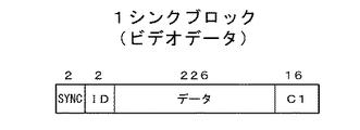
12トラックのビデオデータ領域ARVL,ARVUには、図4に示すように、ブロック0〜ブロック35までの、36個のECCブロック(符号化単位のデータ)が記録される。1個のECCブロックは、以下のように構成されている。すなわち、226バイト×114バイトのデータ配列からなるビデオデータに対して、矢印bで示す外符号演算データ系列につき、各列のデータ(データ列)が例えば(126,114)リードソロモン符号によって符号化され、12バイトのC2パリティ(外符号パリティ)が生成される。さらに、これらビデオデータおよびC2パリティに対して、矢印aで示す内符号演算データ系列につき、各行のデータ(データ列)が例えば(242,226)リードソロモン符号によって符号化され、16バイトのC1パリティが生成される。また、各々のデータ行の先頭には、それぞれ2バイトの大きさを有するシンクデータおよびIDが配される。
【0039】
図5は、ECCブロックにおける1シンクブロックの構成を示している。先頭の2バイトはシンクデータである。続く2バイトはIDである。このIDには、当該1シンクブロックが12トラックのいずれに記録されたものかを識別するトラックID、当該1シンクブロックが一本の傾斜トラックに記録された複数のシンクブロックのいずれであるかを識別するシンクブロックIDが含まれる。
【0040】
例えば、シンクブロックIDは、9ビットのデータとして構成される。この場合、1ビットで、走査開始端側のビデオデータ領域ARVLに記録されるものか、走査終了端側のビデオデータ領域ARVUに記録されるものかを表すものとされる。また、残りの8ビットで、領域ARVL,ARVUのそれぞれに記録される189シンクブロックにそれぞれ対応して0〜188の数値が与えられる。
【0041】
また、12トラック毎に1セグメントが構成され、0〜3のセグメント番号が順次繰り返し付与されるが、上述の2バイトのIDには、当該1シンクブロックが記録されるセグメントのセグメント番号を示すセグメントIDも含まれる。
【0042】
また、このIDに、226バイトのビデオデータ(またはC2パリティ)および16バイトのC1パリティが続く。
【0043】
上述したように、磁気テープ120の12トラックに、36個のECCブロック(図4参照)が記録される。図6は、1セグメントを構成する12トラックのビデオデータ領域ARVL,ARVUにおける各ECCブロックのシンクブロックの配置を示している。
【0044】
図6Aに示すように、1回目にスキャンされる0〜3の4トラックに関しては、ビデオデータ領域ARVLには0〜35のECCブロックにおける0Row〜20Rowまでの21Rowのシンクブロックが記録され、ビデオデータ領域ARVUには0〜35のECCブロックにおける21Row〜41Rowまでの21Rowのシンクブロックが記録される。
【0045】
また、2回目にスキャンされる4〜7の4トラックに関しては、ビデオデータ領域ARVLには0〜35のECCブロックにおける42Row〜62Rowまでの21Rowのシンクブロックが記録され、ビデオデータ領域ARVUには0〜35のECCブロックにおける63Row〜83Rowまでの21Rowのシンクブロックが記録される。
【0046】
さらに、3回目にスキャンされる8〜11の4トラックに関しては、ビデオデータ領域ARVLには0〜35のECCブロックにおける84Row〜104Rowまでの21Rowのシンクブロックが記録され、ビデオデータ領域ARVUには0〜35のECCブロックにおける105Row〜125Rowまでの21Rowのシンクブロックが記録される。
【0047】
ここで、0Rowのシンクブロックは、0〜35のECCブロックのそれぞれにおける0番目のシンクブロックからなっており、これら36個のシンクブロックは、図6Bに示すように、0〜4のトラックに、9シンクブロックずつ振り分けられて記録される。つまり、0のトラックには0,18,1,19,2,20,3,21,4のECCブロックにおける0番目のシンクブロックが記録され、1のトラックには22,5,23,6,24,7,25,8,26のECCブロックにおける0番目のシンクブロックが記録され、2のトラックには9,27,10,28,11,29,12,30,13のECCブロックにおける0番目のシンクブロックが記録され、さらに3のトラックには31,14,32,15,33,16,34,17,35のECCブロックにおける0番目のシンクブロックが記録される。
【0048】
以下、同様に、1〜125Rowのシンクブロックは、それぞれ0〜35のECCブロックにおける1〜125番目のシンクブロックからなっており、各36個のシンクブロックは対応する4トラックに9シンクブロックずつ振り分けられて記録される。この場合、Row毎に、4トラックのそれぞれに記録される9シンクブロックが取り出されるECCブロックがローテーションされる。なお、1シンクブロックは、図6Cに示すように、2バイトのシンクデータ、2バイトのID、226バイトのビデオデータ(またはC2パリティ)および16バイトのC1パリティからなっている。
【0049】
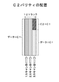
ここで、0〜11の12トラックには、0Row〜125Rowのシンクブロックが順次記録される。この場合、0Row〜113Rowのシンクブロックは、内符号演算データ系列を構成するビデオデータのデータ列にC1パリティが付加されてなるものであるが、114Row〜125Rowのシンクブロックは、内符号演算データ系列を構成するC2パリティのデータ列にC1パリティが付加されてなるものである。
【0050】
つまり、本実施の形態においては、12トラックに0〜35の36個のECCブロックを記録する際に、図7に示すように、最初は内符号演算データ系列を構成するビデオデータのデータ列にC1パリティが付加されてなる第1のシンクブロックが順次記録され、この第1のシンクブロックの記録が終了した後に、内符号演算データ系列を構成するC2パリティのデータ列にC1パリティが付加されてなる第2のシンクブロックが順次記録される。
【0051】
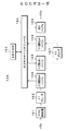
次に、図1に示す記録再生装置100におけるECCエンコーダ113の詳細を説明する。図8は、ECCエンコーダ113の構成を示している。
【0052】
このECCエンコーダ113は、SDRAM(Synchronous Dynamic RAM)151と、このSDRAM151に対する書き込みおよび読み出しを行うためのインタフェースであるSDRAMインタフェース152とを有している。SDRAM151は、複数フィールドのビデオデータを記憶し得る容量を持っている。この場合、SDRAM151には、各フィールドについて、36個のECCブロック(図4参照)に対応したメモリ空間が用意されている。
【0053】
また、ECCエンコーダ113は、ビデオ圧縮回路112から供給されるビデオデータ(圧縮符号化データ)VDaをSDRAM151に書き込むためのバッファとなる入力書き込みバッファ153を有している。ここで、入力書き込みバッファ153は、パッキング手段も構成しており、ビデオ圧縮回路112から供給されるビデオデータ(圧縮符号化データ)VDaをシンクブロックにパッキングする。
【0054】
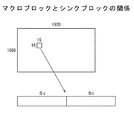
上述したようにビデオ圧縮回路112では、ビデオデータVinが例えば8×8画素の二次元ブロックに分割され、DCT等のブロック符号化を用いたデータ圧縮処理が行われる。上述せずも、有効画面は、1920画素×1088ラインで構成される。入力書き込みバッファ153では、図9に示すように、16×16画素のマクロブロック(8×8画素のDCTブロックが4個で構成される)の圧縮符号化データ毎に、2個のシンクブロックSd,Shにパッキングされる。
【0055】
ここで、シンクブロックSdは、第1のシンクブロックを構成しており、変速再生時に単独で再生したとき、使用できるシンクブロックである。このシンクブロックSdには、DC係数を含む低域周波数領域の係数がパッキングされる。また、シンクブロックShは、第2のシンクブロックを構成しており、変速再生時に単独で再生したとき、使用できないシンクブロックである。このシンクブロックShには、シンクブロックSdにパッキングされる係数を除く、高域周波数領域の係数がパッキングされる。
【0056】
SDRAM151には、各マクロブロックの圧縮符号化データがパッキングされたシンクブロックSd,Shが、各フィールドにつき、36個のECCブロックに対応したメモリ空間に順次書き込まれる。図6に示すように、36個のECCブロックの各シンクブロックがシャフリングされて傾斜トラックに記録される。各マクロブロックの圧縮符号化データがパッキングされたシンクブロックSd,ShをSDRAM151の36個のECCブロックに対応したメモリ空間に書き込む際に、図10に示すように、同一のマクロブロックに係るシンクブロックSd,Shが連続して記録されるように、SDRAM151における書き込みアドレスが制御される。なお、図10において、矢印SCNは、変速再生時における、再生ヘッドの走査軌跡の一例を示している。
【0057】
つまり、36個のECCブロックの各シンクブロックが図6Bに示すように記録される場合、0,18のECCブロックの0番目のシンクブロック、1,19のECCブロックの0番目のシンクブロック、2,20のECCブロックの0番目のシンクブロック、・・・に対応したメモリ空間には、それぞれ同一のマクロブロックに係るシンクブロックSd,Shが書き込まれる。
【0058】
図8に戻って、また、ECCエンコーダ113は、各フィールドについて、SDRAM151から読み出される36個のECCブロックに対応したビデオデータを後述するC2エンコーダ155に供給するためのバッファとなるC2読み出しバッファ154と、各フィールドについて、36個のECCブロックにおけるC2パリティ(外符号パリティ)を演算するC2エンコーダ155とを有している。
【0059】
この場合、C2エンコーダ155は、C2パリティを演算する演算器を例えば36個有しており、上述した36個のECCブロックにおけるC2パリティを並行して演算できる。そのため、C2読み出しバッファ154からC2エンコーダ155には、36個のECCブロックに対応したビデオデータが並行して供給される。
【0060】
また、ECCエンコーダ113は、各フィールドについて、C2エンコーダ155で演算された36個のECCブロックにおけるC2パリティをSDRAM151に書き込むためのバッファとなるC2書き込みバッファ156と、各フィールドについて、SDRAM151から読み出される、36個のECCブロックに対応したビデオデータおよびC2パリティを出力するためのバッファとなる出力バッファ157とを有している。
【0061】
また、ECCエンコーダ113は、出力バッファ157から記録順に出力される各シンクブロックのビデオデータ(またはC2パリティ)のデータ列に、シンクデータおよびIDを付加するSYNC・ID付加回路158と、このSYNC・ID付加回路158でシンクデータおよびIDが付加された各シンクブロックのビデオデータに対してC1パリティを演算して付加し、記録ビデオデータVDbとして出力するC1エンコーダ159とを有している。
【0062】
図8に示すECCエンコーダ113の動作を説明する。
ビデオ圧縮回路112(図1参照)より供給されるビデオデータ(圧縮符号化データ)VDaは、入力書き込みバッファ153およびSDRAMインタフェース152を介してSDRAM151に書き込まれる。この場合、16×16画素のマクロブロックの圧縮符号化データ毎に、2個のシンクブロックSd,Shにパッキングされ、これらシンクブロックSd,Shが、各フィールドにつき、36個のECCブロックに対応したメモリ空間に順次書き込まれる。
【0063】
この場合、同一のマクロブロックに係るシンクブロックSd,Shが傾斜トラックに連続して記録されるように(図10参照)、SDRAM151における書き込みアドレスが制御される。ここで、シンクブロックSdは、変速再生時に単独で再生したとき使用できる第1のシンクブロックを構成している。このシンクブロックSdには、DC係数を含む低域周波数領域の係数がパッキングされる。また、シンクブロックShは、変速再生時に単独で再生したとき使用できない第2のシンクブロックを構成している。このシンクブロックShには、シンクブロックSdにパッキングされる係数を除く、高域周波数領域の係数がパッキングされる。
【0064】
また、各フィールドについて、SDRAM151から読み出される36個のECCブロックに対応したビデオデータは、SDRAMインタフェース152およびC2読み出しバッファ154を介してC2エンコーダ155に供給される。この場合、C2読み出しバッファ154からC2エンコーダ155には、36個のECCブロックに対応したビデオデータが並行して供給される。
【0065】
C2エンコーダ155では、各フィールドについて、36個の演算器によって、36個のECCブロックにおけるC2パリティが並行して演算される。このように各フィールドについて、C2エンコーダ155で演算される、36個のECCブロックにおけるC2パリティは、C2書き込みバッファ156およびSDRAMインタフェース152を介して、SDRAM151の、対応する36個のECCブロックのメモリ空間におけるC2パリティ領域に書き込まれる。
【0066】
また、各フィールドについて、SDRAM151から読み出される36個のECCブロックに対応したビデオデータおよびC2パリティは、SDRAMインタフェース152を介して出力バッファ157に供給される。この出力バッファ157から記録順に出力される各シンクブロックのビデオデータ(またはC2パリティ)は、SYNC・ID付加回路158でシンクデータおよびIDが付加された後にC1エンコーダ159に供給される。
【0067】
C1エンコーダ159では、シンクデータおよびIDが付加された各シンクブロックのビデオデータに対してC1パリティが演算されて付加され、記録ビデオデータVDbとしての各シンクブロックが生成される。この記録ビデオデータVDbは、上述したように記録アンプ114(図1参照)に供給される。
【0068】
次に、図1に示す記録再生装置100におけるECCデコーダ134の詳細を説明する。図11は、ECCデコーダ134の構成を示している。
【0069】
このECCデコーダ134は、復号回路133から供給される再生ビデオデータVDcを構成する各シンクブロックのシンクデータを検出するSYNC検出回路161と、このSYNC検出回路161を通じて供給される各シンクブロック毎にC1パリティを用いてエラー訂正処理を行うC1デコーダ162とを有している。C1デコーダ162からは、エラー訂正処理後のビデオデータ列に、エラー訂正ができたか否かを示すエラー訂正フラグおよびIDが付加された状態で、各シンクブロックが出力される。エラー訂正フラグは、シンクデータの部分に挿入される。この場合、エラー訂正フラグがエラー訂正ができたことを示す状態にある場合、そのエラー訂正フラグが付加されているビデオデータ列にはエラーは含まれておらず、一方エラー訂正フラグがエラー訂正ができなかったことを示す状態にある場合、そのエラー訂正フラグが付加されているビデオデータ列にはエラーが含まれている。
【0070】
また、ECCデコーダ134は、SDRAM163と、このSDRAM163に対する書き込みおよび読み出しを行うためのインタフェースであるSDRAMインタフェース164とを有している。SDRAM163は、複数フィールドのビデオデータを記憶し得る容量を持っている。この場合、SDRAM163には、各フィールドについて、36個のECCブロック(図4参照)に対応したメモリ空間が用意されている。
【0071】
また、ECCデコーダ134は、C1デコーダ162から供給される各シンクブロックをSDRAM163に書き込むためのバッファとなる入力書き込みバッファ165を有している。
【0072】
ここで、入力書き込みバッファ165は、通常再生時には、後述するように、C2デコーダによってC2パリティを用いたエラー訂正処理が行われることから、付加されているエラー訂正フラグの状態によらず、全てのシンクブロックをSDRAM163に書き込む。この場合、各シンクブロックは、それに付加されているトラックIDおよびシンクブロックIDに基づいて、各フィールドにつき、36個のECCブロックに対応したメモリ空間の所定アドレス位置に書き込まれる。これにより、SDRAM163には、各フィールドにつき、それぞれ記録時と同様の126個のシンクブロックからなる、36個のECCブロックが生成される。
【0073】
また、入力書き込みバッファ165は、磁気テープ120の走行速度を通常再生時より速くあるいは遅くして再生を行う変速再生時には、C1デコーダ162から供給されるシンクブロックのうち、以下の選択処理で選択されたシンクブロックのみ、SDRAM163に書き込む。この場合も、各シンクブロックは、それに付加されているトラックIDおよびシンクブロックIDに基づいて、36個のECCブロックに対応したメモリ空間の所定アドレス位置に書き込まれる。この場合、各フィールドにおいて同一のメモリ空間に書き込みが行われ、記憶データが順次更新されていく。
【0074】
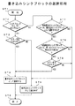
図12のフローチャートは、選択処理の手順を示している。
ステップST1で処理を開始し、ステップST2で、再生されたシンクブロックが、シンクブロックSd、Shのいずれかかを判定する。この判定は、シンクブロックIDに基づいて行われる。シンクブロックSdであると判定するときは、ステップST3で、当該シンクブロックがC1パリティによってエラー訂正できたものであるか否かを判定する。この判定は、エラー訂正フラグに基づいて行われる。
【0075】
エラー訂正できたものであるときは、ステップST4で、当該シンクブロックを書き込みシンクブロックとして選択し、ステップST5で処理を終了する。一方、エラー訂正できたものでないときは、ステップST6で、当該シンクブロックを書き込みシンクブロックとして選択しないこととし、ステップST5で処理を終了する。
【0076】
上述のステップST2でシンクブロックShであると判定するときは、ステップST7で、直前に再生されたシンクブロックSdが、エラー訂正できて書き込みシンクブロックとして選択されたか否かを判定する。書き込みシンクブロックとして選択されたときは、ステップST8で、当該シンクブロックが、直前に再生されたシンクブロックSdと同一のマクロブロックに係るものであるか否かを判定する。この判定はトラックIDおよびシンクブロックIDに基づいて行われる。
【0077】
すなわち、当該シンクブロックにおけるトラックIDが直前に再生されたシンクブロックSdにおけるトラックIDと同一であり、かつ当該シンクブロックにおけるシンクブロックIDが直前に再生されたシンクブロックSdにおけるシンクブロックIDに連続したものであるとき、当該シンクブロックは、直前に再生されたシンクブロックSdと同一のマクロブロックに係るものであると判定する。
【0078】
ステップST8で同一のマクロブロックに係るものであると判定するときは、ステップST9で、当該シンクブロックがC1パリティによってエラー訂正できたものであるか否かを判定する。この判定は、エラー訂正フラグに基づいて行われる。
【0079】
エラー訂正できたものであるときは、ステップST4で、当該シンクブロックを書き込みシンクブロックとして選択し、ステップST5で処理を終了する。ステップST7で直前に再生されたシンクブロックSdが書き込みブロックとして選択されなかったとき、ステップST8で当該シンクブロックが直前に再生されたシンクブロックSdと同一のマクロブロックに係るものでないとき、およびステップST9で当該シンクブロックがエラー訂正できたものでないときは、ステップST6で、当該シンクブロックを書き込みシンクブロックとして選択しないこととし、ステップST5で処理を終了する。
【0080】
また、入力書き込みバッファ165は、シンクブロックSdをSDRAM163に書き込む際に、このシンクブロックSdと同一のマクロブロックに係るシンクブロックShを書き込むことができないとき、当該シンクブロックSdに後シンクエラーフラグを付加してSDRAM163に書き込む。この状況は、再生されたシンクブロックSdが書き込みシンクブロックとして選択されるが、その直後に再生されたシンクブロックShが、当該シンクブロックSdと同一のマクロブロックに係るものでないか、あるいはエラー訂正できたものでなく、書き込みシンクブロックとして選択されなかった場合に、発生する。
【0081】
このようにシンクブロックSdに後シンクエラーフラグを付加してSDRAM163に書き込むのは、SDRAM163に記憶されている当該シンクブロックSdとペアになるべきシンクブロックShは、当該シンクブロックSdと同一のマクロブロックに係るものではなく、例えば後段のビデオ伸長回路135で、そのシンクブロックShに含まれる圧縮符号化データの使用を防止可能とするためである。
【0082】
図11に戻って、また、ECCデコーダ134は、各フィールドについて、SDRAM163から読み出される36個のECCブロックにおける各シンクブロックのデータを後述するC2デコーダ167に供給するためのバッファとなるC2読み出しバッファ166と、各フィールドについて、36個のECCブロックにおいてC2パリティを用いてエラー訂正処理を行うC2デコーダ167と、各フィールドについて、C2デコーダ167で訂正された36個のECCブロックにおけるビデオデータ(圧縮符号化データ)をSDRAM163に書き込むためのバッファとなるC2書き込みバッファ168とを有している。
【0083】
なお、これらバッファ166,168およびC2デコーダ167の部分は、通常再生時にのみ使用される。つまり、変速再生時には、C2パリティを用いたエラー訂正処理は行われない。
【0084】
また、ECCデコーダ134は、各フィールドについて、SDRAM163に記憶されている36個のECCブロックに基づいて、各マクロブロックの圧縮符号化データを出力するためのバッファとなる出力バッファ169を有している。この場合、出力バッファ169は、デパッキングの処理を行って、各マクロブロックの圧縮符号化データを対応するシンクブロックSd,Shから取得する。
【0085】
なお、出力バッファ169は、変速再生時には、所定のマクロブロックの圧縮符号化データを得るためのシンクブロックSdに後シンクエラーフラグが付加されている場合には、当該所定のマクロブロックの圧縮符号化データのうち、シンクブロックShから取得した圧縮符号化データに関しては、エラーフラグを付加して出力する。これにより、後段のビデオ伸長回路135では、エラーフラグが付加されている圧縮符号化データを誤って使用することを防止できる。
【0086】
図11に示すECCデコーダ134の動作を説明する。最初に通常再生時の動作を説明する。
【0087】
復号回路133から供給される再生ビデオデータVDcはSYNC検出回路161でシンクデータが検出され、その後にC1デコーダ162に供給される。C1デコーダ162では、各シンクブロックに対して、C1パリティを用いたエラー訂正処理が行われる。このC1デコーダ162からは、エラー訂正処理後のビデオデータ列に、エラー訂正ができたか否かを示すエラー訂正フラグおよびIDが付加された状態で、各シンクブロックが出力される。
【0088】
C1デコーダ162から出力される各シンクブロックは、入力書き込みバッファ165およびSDRAMインタフェース164を介して、SDRAM163に書き込まれる。この場合、各シンクブロックは、それに付加されているトラックIDおよびシンクブロックIDに基づいて、各フィールドについて、36個のECCブロックに対応したメモリ空間の所定アドレス位置に書き込まれる。これにより、SDRAM163には、各フィールドにつき、それぞれ記録時と同様の126個のシンクブロックからなる、36個のECCブロックが生成される。
【0089】
また、各フィールドについて、SDRAM163から36個のECCブロックにおける各シンクブロックのデータが読み出され、SDRAMインタフェース164およびC2読み出しバッファ166を介してC2デコーダ167に供給される。C2デコーダ167では、各フィールドにつき、36個のECCブロックにおいて、C2パリティを用いてエラー訂正処理が行われる。そして、各フィールドについて、C2デコーダ167で訂正された36個のECCブロックにおけるビデオデータ(圧縮符号化データ)は、C2書き込みバッファ168およびSDRAMインタフェース164を介して、SDRAM163に書き込まれる。
【0090】
また、各フィールドについて、SDRAM163に記憶されている36個のECCブロックに基づいて、各マクロブロックの圧縮符号化データが読み出され、出力バッファ169を介して出力される。この場合、出力バッファ169では、デパッキングの処理が行われ、各マクロブロックの圧縮符号化データが、対応するシンクブロックSd,Shから取得される。
【0091】
次に、変速再生時の動作を説明する。
復号回路133から供給される再生ビデオデータVDcはSYNC検出回路161でシンクデータが検出され、その後にC1デコーダ162に供給される。C1デコーダ162では、各シンクブロックに対して、C1パリティを用いたエラー訂正処理が行われる。このC1デコーダ162からは、エラー訂正処理後のビデオデータ列に、エラー訂正ができたか否かを示すエラー訂正フラグおよびIDが付加された状態で、各シンクブロックが出力される。
【0092】
C1デコーダ162から出力される各シンクブロックは、入力書き込みバッファ165およびSDRAMインタフェース164を介して、SDRAM163に書き込まれる。この場合、C1デコーダ162から供給されるシンクブロックのうち、選択されたシンクブロックのみ、SDRAM163に書き込まれる。つまり、シンクブロックSdに関しては、C1パリティによってエラー訂正できた場合には、書き込みシンクブロックとして選択される。また、シンクブロックShに関しては、直前に再生されたシンクブロックSdが書き込みブロックとして選択され、当該シンクブロックShが直前に再生されたシンクブロックSdと同一のマクロブロックに係るものであり、かつ当該シンクブロックShがC1パリティによってエラー訂正できた場合には、書き込みシンクブロックとして選択される。
【0093】
この場合、各シンクブロックは、それに付加されているトラックIDおよびシンクブロックIDに基づいて、36個のECCブロックに対応したメモリ空間の所定アドレス位置に書き込まれる。この場合、各フィールドにおいて同一のメモリ空間に書き込みが行われ、記憶データが順次更新されていく。
【0094】
またこの場合、シンクブロックSdがSDRAM163に書き込まれるが、このシンクブロックSdと同一のマクロブロックに係るシンクブロックShがSDRAM163に書き込まれないとき、当該シンクブロックSdに後シンクエラーフラグが付加されてSDRAM163に書き込まれる。
【0095】
また、各フィールドについて、SDRAM163に記憶されている36個のECCブロックに基づいて、各マクロブロックの圧縮符号化データが読み出され、SDRAMインタフェース164および出力バッファ169を介して出力される。この場合、各マクロブロックの圧縮符号化データは、対応するシンクブロックSd,Shから取得される。
【0096】
ここで、所定のマクロブロックの圧縮符号化データを得るためのシンクブロックSdに、後シンクエラーフラグが付加されている場合には、当該所定のマクロブロックの圧縮符号化データのうち、シンクブロックShから取得した圧縮符号化データに関しては、エラーフラグが付加されて出力される。この場合、SDRAM163上でシンクブロックSdとペアであるシンクブロックShには、実際には同一のマクロブロックに係る圧縮符号化データが含まれていない。これにより、後段のビデオ伸長回路135では、エラーフラグが付加されている圧縮符号化データを誤って使用することを防止でき、他のブロックの圧縮符号化データが混じることによる画質の劣化を防止できる。
【0097】
以上説明したように、本実施の形態においては、磁気テープ120の傾斜トラックTには、同一のマクロブロックに係るシンクブロックSd,Shが連続して記録される(図10参照)。したがって、変速再生時に、同一のマクロブロックに係るシンクブロックSd,Shをペアで容易に再生でき、画質の向上を図ることができる。
【0098】
また、本実施の形態においては、変速再生時において、再生されたシンクブロックShについては、直前に再生されたシンクブロックSdがSDRAM163に書き込まれないとき、当該シンクブロックShと直前に再生されたシンクブロックSdとが同一のマクロブロックに係るものでないとき、さらには当該シンクブロックShがC1パリティによってエラー訂正できないときは、SDRAM163に書き込まないものであり、使用不可能なシンクブロックShをSDRAM163に書き込む無駄を防止できる。
【0099】
なお、上述実施の形態においては、ブロック毎の圧縮符号化データが16×16画素のマクロブロック毎の圧縮符号化データであるものを示したが、これに限定されるものではない。例えば、ブロック毎の圧縮符号化データが、8×8のDCTブロックの圧縮画像データであってもよい。
【0100】
また、上記実施の形態においては、マクロブロック毎の圧縮符号化データを2個のシンクブロックSd,Shにパッキングするものを示したが、ブロック毎の圧縮符号化データをパッキングするシンクブロックの数は2個に限定されるものではない。
【0101】
また、上記実施の形態においては、DCT等のブロック符号化を用いたデータ圧縮処理が行われるものであるが、DCTの他にウォーブレット変換、離散サイン変換等の直交変換を用いた符号化処理、あるいはその他の符号化処理を行ってもよい。要は、ブロック毎の圧縮符号化データを複数個のシンクブロックにパッキングした場合、変速再生時に単独で再生したとき、使用できる第1のシンクブロックと、使用できない第2のシンクブロックとを、得ることができるものであればよい。
【0102】
【発明の効果】
この発明によれば、ビデオデータを二次元ブロック単位で分割して圧縮符号化し、各ブロックの圧縮符号化データを複数のブロックに渡ってパッキングし、テープの傾斜トラックに、同一のブロックに係る第1、第2のシンクブロック(変速再生時に単独で再生したとき、第1のシンクブロックは使用できるが、第2のシンクブロックは使用できない)を連続して記録するものであり、変速再生時に同一ブロックに係る第1、第2のシンクブロックをペアで容易に再生でき、画質の向上を図ることができる。
【0103】
また、この発明によれば、上述したように第1、第2のシンクブロックが記録されたテープの傾斜トラックからシンクブロックを再生する際に、第1のシンクブロックについてはエラー訂正できたときはメモリに書き込むが、第2のシンクブロックについては、直前に再生された第1のシンクブロックがエラー訂正でき、この第1のシンクブロックと同一のブロックに係るものであり、かつエラー訂正できたときメモリに書き込むものであり、使用不可能な第2のシンクブロックをメモリに書き込む無駄を防止できる。
【0104】
また、この発明によれば、再生された第1のシンクブロックをメモリに書き込む際に、この第1のシンクブロックと同一のブロックに係る第2のシンクブロックをメモリに書き込まないときは、この第1のシンクブロックに後シンクエラーフラグを付加してメモリに書き込むものであり、この後シンクエラーフラグに基づいて、メモリ上でこの第1のシンクブロックとペアである第2のシンクブロックの圧縮符号化データを用いないようにでき、他のブロックの圧縮符号化データが混じることによる画質の劣化を防止できる。
【図面の簡単な説明】
【図1】実施の形態としての記録再生装置の構成を示すブロック図である。
【図2】記録フォーマットを説明するための図である。
【図3】磁気ヘッドの配置を説明するための図である。
【図4】ビデオデータのECCブロックの構成を示す図である。
【図5】ビデオデータの1シンクブロックの構成を示す図である。
【図6】12トラック内のシンクブロックの配置を説明するための図である。
【図7】C2パリティの配置を示す図である。
【図8】ECCエンコーダの構成を示すブロック図である。
【図9】マクロブロックとシンクブロックとの関係を説明するための図である。
【図10】同一マクロブロックに係る2シンクブロックの配置を示す図である。
【図11】ECCデコーダの構成を示すブロック図である。
【図12】書き込みシンクブロックの選択処理の手順を示すフローチャートである。
【符号の説明】
100・・・記録再生装置、111・・・入力端子、112・・・ビデオ圧縮回路、113・・・ECCエンコーダ、114・・・記録アンプ、120・・・磁気テープ、131・・・再生アンプ、132・・・等化回路、133・・・復号回路、134・・・ECCデコーダ、135・・・ビデオ伸長回路、136・・・出力端子、140・・・回転ドラム、151・・・SDRAM、152・・・SDRAMインタフェース、153・・・入力書き込みバッファ、154・・・C2読み出しバッファ、155・・・C2エンコーダ、156・・・C2書き込みバッファ、157・・・出力バッファ、158・・・SYNC・ID付加回路、159・・・C1エンコーダ、161・・・SYNC検出回路、162・・・C1デコーダ、163・・・SDRAM、164・・・SDRAMインタフェース、165・・・入力書き込みバッファ、166・・・C2読み出しバッファ、167・・・C2デコーダ、168・・・C2書き込みバッファ、169・・・出力バッファ[0001]
BACKGROUND OF THE INVENTION
The present invention is suitable for application to, for example, a digital video tape recorder. Re The present invention relates to a live method and a data reproduction apparatus.
[0002]
Specifically, this invention As a plurality of sync blocks for packing video data that has been compression-encoded in units of two-dimensional blocks, the sync block that can be used when the playback is performed independently at the time of variable speed playback is the first sync block, and the unusable sync block is the second In this case, the inclined track of the tape on which the first and second sync blocks related to the same two-dimensional block are sequentially recorded is scanned with the reproducing head, and the first and second sync blocks are recorded. By playing the block, Data that allows the first and second sync blocks related to the same block to be easily reproduced in pairs during variable speed reproduction Regeneration Methods and data Regeneration It concerns the device.
[0003]
The present invention also provides At the time of variable speed reproduction, the reproduced first sync block is subjected to error correction processing with the added parity, and when the error can be corrected, the first sync block is moved to the address position of the memory corresponding to the first sync block. For the second sync block that has been written and played back by one sync block, the first sync block played back immediately before can be error-corrected and relates to the same block as the first sync block, and Error correction processing is performed with the added parity, and when the error can be corrected, the second sync block is written at the address position of the memory corresponding to the second sync block. Is.
[0004]
[Prior art]
Conventionally, video data is compressed and encoded in units of two-dimensional blocks using, for example, DCT (Discrete Cosine Transform), the compressed encoded data of each block is packed into one sync block, and the data is synced to an inclined track on the tape. A recording / reproducing apparatus that sequentially records blocks, reproduces sync blocks sequentially from the inclined track of the tape, obtains compressed encoded data of each block by depacking processing, and performs video decompression processing to obtain video data It has been proposed (see, for example, Patent Document 1).
[0005]
In such a recording / reproducing apparatus, in order to prevent a burst-like data error from occurring during reproduction and many errors from occurring in the same ECC (Error Correction Code) block, it becomes impossible to perform error correction. In general, recording is performed by shuffling so that the distribution of sync blocks included in the blocks is random on the inclined track of the tape.
[0006]
Further, in such a recording / reproducing apparatus, the reproducing head does not scan along the inclined track during the variable speed reproduction in which the tape travel speed is faster or slower than the normal reproducing time, and the inclined tracks are not scanned. Scan across the screen. Therefore, at the time of variable speed reproduction, not all of the sync blocks recorded on each inclined track can be reproduced, and only a part is reproduced.
[0007]
The reproduced sync block is sequentially written in the address position of the memory corresponding to the sync block, and only the sync block stored in the address position is updated. Then, based on the sync block for one screen stored in the memory, the compressed encoded data of each block is sequentially acquired by the depacking process, the data expansion process is performed, and the reproduced video data is obtained.
[0008]
[Patent Document 1]
JP 09-139910 A
[0009]
[Problems to be solved by the invention]
As in the above-described
[0010]
By the way, when the compression rate is low, the compression encoded data of each block is packed into a plurality of sync blocks. In this case, the sync block recorded on the inclined track of the tape includes a first sync block that can be used and a second sync block that cannot be used when played independently during variable speed playback. For example, when compression encoding using orthogonal transform is performed as described above, the first sync block is a sync block including a DC coefficient, and the second sync block is a sync block including no DC coefficient.
[0011]
That is, in this case, if the first sync block and the second sync block related to the same block can be acquired in pairs, the second sync block can also be used, so that the image quality can be improved. Further, in this case, when the second sync block is reproduced alone, the second sync block cannot be used, so it is useless to write this sync block in the memory.
[0012]
An object of the present invention is to enable easy reproduction of first and second sync blocks related to the same block in pairs during variable speed reproduction. Another object of the present invention is to prevent wasteful writing of the unusable second sync block into the memory.
[0013]
[Means for Solving the Problems]
Data according to the present invention Regeneration The method is Can be used as a plurality of sync blocks for packing video data compressed and encoded in units of two-dimensional blocks when played back independently during variable speed playback where playback is performed faster or slower than the normal running speed of the tape. When the sync block is the first sync block and the unusable sync block is the second sync block, the first and second sync blocks related to the same two-dimensional block are sequentially recorded. The inclined track is scanned with the reproducing head to reproduce the first and second sync blocks, and at the time of variable speed reproduction, the reproduced first sync block is subjected to error correction processing with the added parity, When the error can be corrected, the first address is stored at the address position of the memory corresponding to the first sync block. For the second sync block written and reproduced, the first sync block reproduced immediately before can be error-corrected, is related to the same block as the first sync block, and is added. When the error correction process is performed using the parity, and the error can be corrected, the second sync block is written to the address position of the memory corresponding to the second sync block. Is.
[0014]
In addition, data according to the present invention Regeneration The device Can be used as a plurality of sync blocks for packing video data compressed and encoded in units of two-dimensional blocks when played back independently during variable speed playback where playback is performed faster or slower than the normal running speed of the tape. When the sync block is the first sync block and the unusable sync block is the second sync block, the first and second sync blocks related to the same two-dimensional block are sequentially recorded. Reproducing means for reproducing the first and second sync blocks by scanning the inclined track with the reproducing head, and the first and second sync blocks reproduced by the reproducing means are connected to the first and second sync blocks of the memory. Data writing means for writing to an address position corresponding to the sync block, and the data writing means is for variable speed reproduction. For the reproduced first sync block, error correction processing is performed with the added parity, and when the error can be corrected, the first sync block is located at the address position of the memory corresponding to the first sync block. For the second sync block that was written and played back, the first sync block played back immediately before can be error-corrected, is related to the same block as the first sync block, and is added When the error correction processing is performed with the parity that has been performed and the error has been corrected, the second sync block is written to the address position of the memory corresponding to the second sync block Is.
[0020]
In this invention, the video data is compressed and encoded in units of two-dimensional blocks, the compressed encoded data of each block is packed across a plurality of sync blocks, and the tape block is formed by sequentially recording the sync blocks. The track is scanned with the playhead. Then, the reproduced sync block is written into the address position of the memory corresponding to the sync block.
[0021]
For example, when the distribution of sync blocks included in the same ECC block is recorded after being shuffled so as to be random on the inclined track of the tape, the address of the memory corresponding to the sync block reproduced in this way By writing at the position, the deshuffling process is performed.
[0022]
In this case, there are a first sync block that can be used and a second sync block that cannot be used when reproduced independently at the time of variable speed reproduction as a plurality of sync blocks for packing the compression encoded data of each block. Further, the first sync block and the second sync block related to the same block are continuously recorded on the inclined track.
[0023]
At the time of variable speed reproduction, the reproduced first sync block and second sync block are processed as follows. That is, the reproduced first sync block is written into the memory when error correction can be performed with the added parity. On the other hand, for the second sync block, the first sync block reproduced immediately before can be error-corrected, is related to the same block as the first sync block, and is error-corrected by the added parity. When it is done, it is written to memory.
[0024]
The second sync block can be used only in pairs with the first sync block related to the same block. When the first sync block reproduced immediately before cannot be error-corrected, when it does not relate to the same block as the first sync block reproduced immediately before, and when error correction cannot be performed by the added parity The second sync block cannot be used in a pair with the first sync block related to the same block. In such a case, the second sync block is not written into the memory, and it is possible to prevent wasteful writing of the unusable second sync block into the memory.
[0025]
When writing the regenerated first sync block to the memory, if the second sync block related to the same block as the first sync block is not written to the memory, the first sync block is written to the first sync block. A sync error flag can be added and written to the memory. In that case, based on the post sync error flag, the compression encoded data of the second sync block paired with the first sync block on the memory can be avoided, and the compression code of the other block can be used. Image quality deterioration due to mixed data can be prevented.
[0026]
DETAILED DESCRIPTION OF THE INVENTION
Hereinafter, embodiments of the present invention will be described with reference to the drawings. FIG. 1 shows a basic configuration of a recording / reproducing
[0027]
First, the recording system will be described. Digital video data Vin input to the
[0028]
Video data (compression encoded data) VDa output from the
[0029]
In this case, the recorded video data VDb is recorded in the form of NRZ (Non-Return-to-Zero) without undergoing digital modulation processing. However, the video data VDb may be recorded after being subjected to digital modulation processing.
[0030]
Next, the reproduction system will be described. A reproduction signal reproduced from the recording track of the
[0031]
The reproduced video data VDc output from the
[0032]
The error-corrected video data (compression encoded data) VDd output from the
[0033]
FIG. 2 shows a recording format of the
[0034]
The areas on the scanning start end side and the scanning end end side of the track T are the video data area ARV, respectively. L , ARV U Assigned to. This video data area ARV L , ARV U The recording video data VDb output from the
[0035]
FIG. 3 is a schematic diagram showing the configuration of the rotating drum of the recording / reproducing
[0036]
In addition, four recording heads RECA to RECD are arranged on the
[0037]
The recording head Hr of the recording / reproducing
[0038]
Video data area ARV of 12 tracks L ,
[0039]
FIG. 5 shows the configuration of one sync block in the ECC block. The first two bytes are sync data. The following 2 bytes are ID. This ID includes a track ID for identifying which of the 12 tracks the one sync block is recorded on, and which of the plurality of sync blocks is recorded on one inclined track. A sync block ID to be identified is included.
[0040]
For example, the sync block ID is configured as 9-bit data. In this case, 1-bit video data area ARV on the scanning start end side L Or the video data area ARV on the scanning end side U It is assumed that it is recorded in In the remaining 8 bits, the area ARV L , ARV U A numerical value of 0 to 188 is given corresponding to each of the 189 sync blocks recorded in each of.
[0041]
In addition, one segment is formed for every 12 tracks, and segment numbers of 0 to 3 are repeatedly given. The above-mentioned 2-byte ID is a segment indicating the segment number of the segment in which the one sync block is recorded. An ID is also included.
[0042]
This ID is followed by 226 bytes of video data (or C2 parity) and 16 bytes of C1 parity.
[0043]
As described above, 36 ECC blocks (see FIG. 4) are recorded on 12 tracks of the
[0044]
As shown in FIG. 6A, for the four
[0045]
In addition, with respect to 4 to 4 tracks scanned for the second time, the video
[0046]
Further, regarding the 4
[0047]
Here, the 0Row sync block is composed of the 0th sync block in each of the 0 to 35 ECC blocks, and these 36 sync blocks are arranged on
[0048]
Similarly, the 1 to 125 Row sync blocks are the 1st to 125th sync blocks in the 0 to 35 ECC blocks, and each of the 36 sync blocks is divided into 9 sync blocks for the corresponding 4 tracks. And recorded. In this case, for each row, the ECC block from which nine sync blocks recorded on each of the four tracks are extracted is rotated. As shown in FIG. 6C, one sync block includes 2-byte sync data, 2-byte ID, 226-byte video data (or C2 parity), and 16-byte C1 parity.
[0049]
Here, sync blocks of 0 Row to 125 Row are sequentially recorded on 12 tracks of 0 to 11. In this case, the sync blocks of 0 Row to 113 Row are obtained by adding C1 parity to the data sequence of the video data constituting the inner code calculation data sequence, while the sync blocks of 114 Row to 125 Row are the inner code calculation data sequence. C1 parity is added to the data string of C2 parity that constitutes.
[0050]
That is, in the present embodiment, when 36 ECC blocks of 0 to 35 are recorded on 12 tracks, as shown in FIG. 7, the data sequence of the video data constituting the inner code calculation data sequence is initially set. The first sync block to which the C1 parity is added is sequentially recorded, and after the recording of the first sync block is completed, the C1 parity is added to the C2 parity data string constituting the inner code calculation data sequence. The second sync block is sequentially recorded.
[0051]
Next, details of the
[0052]
The
[0053]
The
[0054]
As described above, in the
[0055]
Here, the sync block Sd constitutes a first sync block, and is a sync block that can be used when reproduced alone during variable speed reproduction. The sync block Sd is packed with coefficients in a low frequency region including DC coefficients. The sync block Sh constitutes a second sync block, and is a sync block that cannot be used when reproduced alone during variable speed reproduction. The sync block Sh is packed with high frequency domain coefficients excluding the coefficients packed into the sync block Sd.
[0056]
In the
[0057]
That is, when each sync block of 36 ECC blocks is recorded as shown in FIG. 6B, 0th sync block of 0,18 ECC block, 0th sync block of 1,19 ECC block, 2 , 20, the sync blocks Sd and Sh related to the same macro block are written in the memory space corresponding to the 0th sync block of the ECC block.
[0058]
Returning to FIG. 8, the
[0059]
In this case, the
[0060]
Further, the
[0061]
Further, the
[0062]
The operation of the
Video data (compression encoded data) VDa supplied from the video compression circuit 112 (see FIG. 1) is written to the
[0063]
In this case, the write address in the
[0064]
For each field, video data corresponding to 36 ECC blocks read from the
[0065]
In the
[0066]
For each field, video data and C2 parity corresponding to 36 ECC blocks read from the
[0067]
In the
[0068]
Next, details of the
[0069]
The
[0070]
The
[0071]
The
[0072]
Here, during normal reproduction, the input write buffer 165 performs error correction processing using C2 parity by the C2 decoder, as will be described later, so that all of the input write buffer 165 does not depend on the state of the added error correction flag. Write the sync block to the
[0073]
The input write buffer 165 is selected by the following selection process from the sync blocks supplied from the
[0074]
The flowchart of FIG. 12 shows the procedure of the selection process.
Processing is started in step ST1, and in step ST2, it is determined whether the reproduced sync block is one of the sync blocks Sd and Sh. This determination is made based on the sync block ID. When it is determined that the block is the sync block Sd, it is determined in step ST3 whether or not the sync block has been error-corrected by the C1 parity. This determination is made based on the error correction flag.
[0075]
If the error has been corrected, the sync block is selected as a write sync block in step ST4, and the process ends in step ST5. On the other hand, if the error cannot be corrected, in step ST6, the sync block is not selected as a write sync block, and the process ends in step ST5.
[0076]
When it is determined in step ST2 that it is a sync block Sh, it is determined in step ST7 whether or not the sync block Sd reproduced immediately before has been error-corrected and selected as a write sync block. If it is selected as a write sync block, it is determined in step ST8 whether or not the sync block is related to the same macro block as the sync block Sd reproduced immediately before. This determination is made based on the track ID and sync block ID.
[0077]
That is, the track ID in the sync block is the same as the track ID in the sync block Sd reproduced immediately before, and the sync block ID in the sync block is continuous with the sync block ID in the sync block Sd reproduced immediately before In this case, the sync block is determined to be related to the same macro block as the sync block Sd reproduced immediately before.
[0078]
When it is determined in step ST8 that the blocks are related to the same macroblock, it is determined in step ST9 whether or not the sync block has been error-corrected by C1 parity. This determination is made based on the error correction flag.
[0079]
If the error has been corrected, the sync block is selected as a write sync block in step ST4, and the process ends in step ST5. When the sync block Sd reproduced immediately before in step ST7 is not selected as a writing block, when the sync block does not relate to the same macro block as the sync block Sd reproduced immediately before in step ST8, and step ST9 If the sync block has not been corrected, in step ST6, the sync block is not selected as a write sync block, and the process ends in step ST5.
[0080]
In addition, when writing the sync block Sd to the
[0081]
In this way, the post sync error flag is added to the sync block Sd and written to the
[0082]
Returning to FIG. 11, the
[0083]
The portions of the
[0084]
Further, the
[0085]
Note that the
[0086]
The operation of the
[0087]
In the reproduced video data VDc supplied from the
[0088]
Each sync block output from the
[0089]
For each field, the data of each sync block in the 36 ECC blocks is read from the
[0090]
In addition, for each field, based on the 36 ECC blocks stored in the
[0091]
Next, the operation during variable speed reproduction will be described.
In the reproduced video data VDc supplied from the
[0092]
Each sync block output from the
[0093]
In this case, each sync block is written at a predetermined address position in the memory space corresponding to 36 ECC blocks based on the track ID and sync block ID added thereto. In this case, writing is performed in the same memory space in each field, and the stored data is sequentially updated.
[0094]
In this case, the sync block Sd is written in the
[0095]
In addition, for each field, based on the 36 ECC blocks stored in the
[0096]
Here, when a post sync error flag is added to the sync block Sd for obtaining the compressed encoded data of the predetermined macroblock, the sync block Sh of the compressed encoded data of the predetermined macroblock is included. The compressed encoded data obtained from the above is output with an error flag added. In this case, the sync block Sh that is paired with the sync block Sd on the
[0097]
As described above, in the present embodiment, sync blocks Sd and Sh related to the same macroblock are continuously recorded on the inclined track T of the magnetic tape 120 (see FIG. 10). Therefore, at the time of variable speed reproduction, the sync blocks Sd and Sh related to the same macroblock can be easily reproduced in pairs, and the image quality can be improved.
[0098]
In the present embodiment, when the sync block Sh reproduced just before the sync block Sh is reproduced in the variable speed reproduction, when the sync block Sd reproduced immediately before is not written in the
[0099]
In the above-described embodiment, the compressed encoded data for each block is the compressed encoded data for each macroblock of 16 × 16 pixels. However, the present invention is not limited to this. For example, the compressed encoded data for each block may be compressed image data of an 8 × 8 DCT block.
[0100]
In the above embodiment, the compression encoded data for each macroblock is packed into two sync blocks Sd and Sh. However, the number of sync blocks for packing the compression encoded data for each block is as follows. The number is not limited to two.
[0101]
In the above embodiment, data compression processing using block coding such as DCT is performed. In addition to DCT, coding processing using orthogonal transformation such as wavelet transform and discrete sine transform is used. Alternatively, other encoding processing may be performed. In short, when compression-coded data for each block is packed into a plurality of sync blocks, a first sync block that can be used and a second sync block that cannot be used are obtained when played back independently during variable speed playback. Anything can be used.
[0102]
【The invention's effect】
According to the present invention, video data is divided and compressed and encoded in units of two-dimensional blocks, the compressed and encoded data of each block is packed across a plurality of blocks, and the tapes on the inclined track are recorded in the same block. 1 and 2 sync blocks (the first sync block can be used, but the second sync block cannot be used when played alone during variable speed playback) are recorded continuously, and the same during variable speed playback The first and second sync blocks related to the block can be easily reproduced in pairs, and the image quality can be improved.
[0103]
According to the present invention, when the sync block is reproduced from the inclined track of the tape on which the first and second sync blocks are recorded as described above, the error can be corrected for the first sync block. When the second sync block is written into the memory, the first sync block reproduced immediately before can be error-corrected, is related to the same block as the first sync block, and the error can be corrected. Writing to the memory, and the waste of writing the unusable second sync block to the memory can be prevented.
[0104]
Further, according to the present invention, when the reproduced first sync block is written to the memory, the second sync block related to the same block as the first sync block is not written to the memory. A sync error flag is added to one sync block and written to the memory. After that, based on the sync error flag, the compression code of the second sync block paired with the first sync block on the memory Therefore, it is possible to prevent the deterioration of the image quality due to the mixing of the compression encoded data of other blocks.
[Brief description of the drawings]
FIG. 1 is a block diagram showing a configuration of a recording / reproducing apparatus as an embodiment.
FIG. 2 is a diagram for explaining a recording format;
FIG. 3 is a diagram for explaining the arrangement of magnetic heads.
FIG. 4 is a diagram illustrating a configuration of an ECC block of video data.
FIG. 5 is a diagram illustrating a configuration of one sync block of video data.
FIG. 6 is a diagram for explaining the arrangement of sync blocks in 12 tracks.
FIG. 7 is a diagram illustrating an arrangement of C2 parity.
FIG. 8 is a block diagram showing a configuration of an ECC encoder.
FIG. 9 is a diagram for explaining a relationship between a macro block and a sync block;
FIG. 10 is a diagram illustrating an arrangement of two sync blocks related to the same macroblock.
FIG. 11 is a block diagram showing a configuration of an ECC decoder.
FIG. 12 is a flowchart illustrating a procedure of write sync block selection processing.
[Explanation of symbols]
DESCRIPTION OF
Claims (4)
使用できない上記シンクブロックを第2のシンクブロックとしたとき、
同一の二次元ブロックに係る上記第1および第2のシンクブロックが順次連続して記録されてなるテープの傾斜トラックを再生ヘッドで走査して当該第1および第2のシンクブロックを再生し、
上記変速再生時には、再生された上記第1のシンクブロックについては、付加されているパリティによってエラー訂正処理を行い、該エラー訂正できたとき、当該第1のシンクブロックに対応するメモリのアドレス位置に当該第1のシンクブロックを書き込み、再生された上記第2のシンクブロックについては、直前に再生された上記第1のシンクブロックがエラー訂正でき、該第1のシンクブロックと同一のブロックに係るものであり、かつ付加されているパリティによってエラー訂正処理を行い、該エラー訂正できたとき、当該第2のシンクブロックに対応するメモリのアドレス位置に当該第2のシンクブロックを書き込むデータ再生方法。 Can be used as a plurality of sync blocks for packing video data compressed and encoded in units of two-dimensional blocks when played back independently during variable speed playback where playback is performed faster or slower than the normal running speed of the tape. The sync block is the first sync block,
When the sync block that cannot be used is the second sync block,
By scanning the inclined tracks of the same tape the according to the two-dimensional blocks the first and second sync blocks, which are recorded sequentially and continuously by the reproducing head to reproduce the first and second sync blocks,
When the variable speed reproduction, the reproduced the first sync block, an error correction processing by parity added, when uncorrectable the error, the address location of the memory corresponding to the first sync block writing the first sync block, the regenerated the second sync block, those immediately before the reproduced the first sync block can be error corrected, according to the same block and a sync block of the first , and the and performs error correction processing by parity added, when uncorrectable the error, the write Mude over data write second sync the address position of the memory corresponding to the block second sync blocks Playback method.
使用できない上記シンクブロックを第2のシンクブロックとしたとき、
同一の二次元ブロックに係る上記第1および第2のシンクブロックが順次連続して記録されてなるテープの傾斜トラックを再生ヘッドで走査して当該第1および第2のシンクブロックを再生する再生手段と、
上記再生手段で再生された第1および第2のシンクブロックを、メモリの当該第1および第2のシンクブロックに対応するアドレス位置に書き込むデータ書き込み手段とを備え、
上記データ書き込み手段は、
上記変速再生時には、再生された上記第1のシンクブロックについては、付加されているパリティによってエラー訂正処理を行い、該エラー訂正できたとき、当該第1のシンクブロックに対応するメモリのアドレス位置に当該第1のシンクブロックを書き込み、再生された上記第2のシンクブロックについては、直前に再生された上記第1のシンクブロックがエラー訂正でき、該第1のシンクブロックと同一のブロックに係るものであり、かつ付加されているパリティによってエラー訂正処理を行い、該エラー訂正できたとき、当該第2のシンクブロックに対応するメモリのアドレス位置に当該第2のシンクブロックを書き込むデータ再生装置。 Can be used as a plurality of sync blocks for packing video data compressed and encoded in units of two-dimensional blocks when played back independently during variable speed playback where playback is performed faster or slower than the normal running speed of the tape. The sync block is the first sync block,
When the sync block that cannot be used is the second sync block,
By scanning the same in the first and second sync blocks playback head oblique tracks of a tape which is being recorded sequentially and continuously according to the two-dimensional blocks and reproduces the first and second sync block reproduction Means,
The first and second sync blocks reproduced by said reproducing means, and a data writing means for writing the address position corresponding to the first and second sync blocks of memory,
The upper Symbol data writing means,
At the time of the variable speed reproduction, the reproduced first sync block is subjected to error correction processing with the added parity , and when the error can be corrected , the address is stored in the memory corresponding to the first sync block. writing the first sync block, the regenerated the second sync block, those immediately before the reproduced the first sync block can be error corrected, according to the same block and a sync block of the first , and the and performs error correction processing by parity added, when uncorrectable the error, the write Mude over data write second sync the address position of the memory corresponding to the block second sync blocks Playback device.
上記再生された第1のシンクブロックを上記メモリに書き込む際に、該第1のシンクブロックと同一ブロックに係る第2のシンクブロックを上記メモリに書き込まないときは、該第1のシンクブロックに後シンクエラーフラグを付加して上記メモリに書き込む請求項3に記載のデータ再生装置。The data writing means is
When writing the regenerated first sync block to the memory, if the second sync block related to the same block as the first sync block is not written to the memory, the first sync block is written to the first sync block. data reproducing apparatus according to write no請 Motomeko 3 written to the memory by adding a sync error flag.
Priority Applications (1)
| Application Number | Priority Date | Filing Date | Title |
|---|---|---|---|
| JP2003101298A JP4264635B2 (en) | 2003-04-04 | 2003-04-04 | Data reproduction method and data reproduction apparatus |
Applications Claiming Priority (1)
| Application Number | Priority Date | Filing Date | Title |
|---|---|---|---|
| JP2003101298A JP4264635B2 (en) | 2003-04-04 | 2003-04-04 | Data reproduction method and data reproduction apparatus |
Publications (2)
| Publication Number | Publication Date |
|---|---|
| JP2004312228A JP2004312228A (en) | 2004-11-04 |
| JP4264635B2 true JP4264635B2 (en) | 2009-05-20 |
Family
ID=33465140
Family Applications (1)
| Application Number | Title | Priority Date | Filing Date |
|---|---|---|---|
| JP2003101298A Expired - Fee Related JP4264635B2 (en) | 2003-04-04 | 2003-04-04 | Data reproduction method and data reproduction apparatus |
Country Status (1)
| Country | Link |
|---|---|
| JP (1) | JP4264635B2 (en) |
-
2003
- 2003-04-04 JP JP2003101298A patent/JP4264635B2/en not_active Expired - Fee Related
Also Published As
| Publication number | Publication date |
|---|---|
| JP2004312228A (en) | 2004-11-04 |
Similar Documents
| Publication | Publication Date | Title |
|---|---|---|
| JP3043268B2 (en) | Digital video recording and reproducing method with improved error correction capability | |
| JP3004252B2 (en) | Digital recording / reproducing apparatus and method with improved error correction capability | |
| EP0683611A2 (en) | A digital recording and reproducing apparatus | |
| JPH09135423A (en) | Apparatus and method for recording diginal signal, apparatusand method for reproducing digital signal | |
| JPH0723333A (en) | Video signal recording and reproducing apparatus | |
| JP4264635B2 (en) | Data reproduction method and data reproduction apparatus | |
| CN1112699C (en) | Audio and video data recording and reproducing apparatus and method | |
| JP3774929B2 (en) | Data reproducing apparatus and data reproducing method | |
| JPH04283473A (en) | Video and audio digital recording/playback equipment | |
| JP3991905B2 (en) | Data recording method and data recording apparatus | |
| JP3991906B2 (en) | Data reproduction method and data reproduction apparatus | |
| JP4042610B2 (en) | Data reproduction method and data reproduction apparatus | |
| JP4107136B2 (en) | Information reproducing apparatus and information reproducing method | |
| JP4106713B2 (en) | Digital information signal recording apparatus and method | |
| JP3864924B2 (en) | Information recording apparatus, information recording method, information reproducing apparatus, information reproducing method, and information recording medium | |
| US7027715B2 (en) | Magnetic-tape recording apparatus, magnetic-tape recording method, magnetic tape, and recording medium | |
| JPWO1998044503A1 (en) | Digital information signal recording device and method | |
| KR100213873B1 (en) | Apparatus and method for trick mode in dvcr | |
| JP3861819B2 (en) | Video signal reproducing apparatus and video signal reproducing method | |
| JP3687428B2 (en) | Digital signal reproduction device | |
| JP3489223B2 (en) | Digital signal recording device and reproducing device | |
| JP3743309B2 (en) | Recording method and recording / reproducing apparatus | |
| JPH07105119B2 (en) | Data storage device using PCM processor | |
| JP2004310860A (en) | Information reproducing apparatus and information reproducing method | |
| JPH06302125A (en) | Digital signal processing device |
Legal Events
| Date | Code | Title | Description |
|---|---|---|---|
| A621 | Written request for application examination |
Free format text: JAPANESE INTERMEDIATE CODE: A621 Effective date: 20060314 |
|
| RD04 | Notification of resignation of power of attorney |
Free format text: JAPANESE INTERMEDIATE CODE: A7424 Effective date: 20060502 |
|
| A131 | Notification of reasons for refusal |
Free format text: JAPANESE INTERMEDIATE CODE: A131 Effective date: 20081104 |
|
| A521 | Written amendment |
Free format text: JAPANESE INTERMEDIATE CODE: A523 Effective date: 20081219 |
|
| TRDD | Decision of grant or rejection written | ||
| A01 | Written decision to grant a patent or to grant a registration (utility model) |
Free format text: JAPANESE INTERMEDIATE CODE: A01 Effective date: 20090120 |
|
| A01 | Written decision to grant a patent or to grant a registration (utility model) |
Free format text: JAPANESE INTERMEDIATE CODE: A01 |
|
| A61 | First payment of annual fees (during grant procedure) |
Free format text: JAPANESE INTERMEDIATE CODE: A61 Effective date: 20090202 |
|
| FPAY | Renewal fee payment (event date is renewal date of database) |
Free format text: PAYMENT UNTIL: 20120227 Year of fee payment: 3 |
|
| LAPS | Cancellation because of no payment of annual fees |