JP4262860B2 - Exhaust structure of grill storage - Google Patents
Exhaust structure of grill storage Download PDFInfo
- Publication number
- JP4262860B2 JP4262860B2 JP2000134143A JP2000134143A JP4262860B2 JP 4262860 B2 JP4262860 B2 JP 4262860B2 JP 2000134143 A JP2000134143 A JP 2000134143A JP 2000134143 A JP2000134143 A JP 2000134143A JP 4262860 B2 JP4262860 B2 JP 4262860B2
- Authority
- JP
- Japan
- Prior art keywords
- grill
- exhaust
- cooking
- communication port
- waste gas
- Prior art date
- Legal status (The legal status is an assumption and is not a legal conclusion. Google has not performed a legal analysis and makes no representation as to the accuracy of the status listed.)
- Expired - Fee Related
Links
Images


Landscapes
- Baking, Grill, Roasting (AREA)
Description
【0001】
【発明の属する技術分野】
本発明は、魚類などの被調理物をグリル庫内の焼網上でガスバーナにより加熱調理する調理用グリルに関し、さらに詳しくは、被調理物の加熱に供されグリル庫内に充満する燃焼廃ガスや被調理物から発生する煙等の排気ダクトからの排気流れの抵抗を減少させるグリル庫の排気構造に関するものである。
【0002】
【従来の技術】
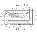
従来からテーブルコンロにおいては、グリル庫内で魚等の被調理物を加熱調理する調理用グリルを組み込んだものは知られている。こうした調理用グリルには、図1に示すように、グリル庫22内に被調理物Fを載置する焼網24と、被調理物からの焼き脂等を受ける受皿28とを備え、グリル庫22内の上方側面に設置される全一次空気式の上バーナ26の燃焼面を斜め上方に向け、その焼網24のやや下方側面にはブンゼン燃焼式の下バーナ27を設けると共に、グリル庫22の奥行部の排気室36への連通口38が焼網24の被調理物F載置面より下方に設けられている。
【0003】
このような構成により、グリル庫22下部の受皿28に溜まった焼き脂等への加熱を低減しつつグリル庫22内での燃焼廃ガスを上方から下方に充満させ、この燃焼廃ガス熱で焼網24上の被調理物Fを加熱調理することにより加熱調理性能を損なうことなく焼き脂の温度を発火点以下に抑えることができ、さらに排気室36のドラフト効果によりグリル庫の手前の隙間47及びギャラリ47aから外部の新鮮な空気が吸引され、受皿28を冷却して後方の連通口38から排出されることにより、受皿28に水を張らなくても焼き脂等の過熱による発火が防止できるという、いわゆる、水無しグリルがある。
【0004】
このような調理用グリルでは、ガスバーナの燃焼廃ガスがグリル庫22内に十分こもって被調理物Fの加熱に供された後、その燃焼廃ガスや被調理物Fから発生する煙等は、焼網24の被調理物F載置面より下方に設けられる連通口38の上部側に集中した流れを形成して排気室36へ流れ、ドラフト効果によって排気ダクト34の排気口32より庫外へ自然排気される。この排気ダクト34の構造として、例えば図7に示すものが知られている。
【0005】
これは図1のB−B断面を示しており、その排気ダクト34が排気上流側より排気下流側に向けて排気面積が一定のストレート構造のものである。この場合、焼き脂が異常過熱されて発火した場合に、その火炎が排気口32から外部に溢れ出すことを防止するために、複数の通気孔が形成された多孔板で火炎の伝播を阻止して消炎させるフレームトラップ33を備えたものもある。
【0006】
【発明が解決しようとする課題】
しかしながら、このような自然排気方式を用いたオーブン的加熱構造の両面焼調理用グリルにおいては、高温の燃焼廃ガスがグリル庫22内に十分こもって被調理物Fの加熱に供された後、その燃焼廃ガスや被調理物Fから発生する煙等は、焼網24の被調理物F載置面より下方に設けられる連通口38の上部を通って排気室36へ流れ、排気ダクト34の排気口32より庫外へ抵抗なくスムーズに排出されることで良好な燃焼性を確保されるが、この図7に示したストレート排気構造のものでは、グリル庫22下方部の下バーナ27等の配設により、排気ダクト34の幅方向の長さが制限されて充分な排気断面積が確保できないため、その燃焼廃ガスや被調理物から発生する煙等の排気の流れが排気室38内で滞留してスムーズにグリル庫22外に排出されなくなり、燃焼廃ガスがグリル庫22内にこもりすぎて燃焼性が悪くなり易く、特に排気口32に前述のフレームトラップ33を備えた場合は、これらの傾向がより大きくなるという問題があった。
【0007】
また、高温の燃焼廃ガスがグリル庫22内にこもり過ぎることで、受皿28に溜まった焼き脂等を過熱することにもなり、またスムーズに排気されないことにより、グリル庫の手前の隙間47及びギャラリ47aから外部の新鮮な空気が、受皿28を冷却するのに十分吸引されなくなり、さらにはブンゼン式の下バーナ27の燃焼に必要な二次空気が不足するという問題もあった。そこでこれを解消しようとするものとして、図8のように排気室36の出口面積を拡大することも考えられる。しかし、このように排気口32を広げても、少しは排気抵抗が減少されるが、十分とは言えなかった。
【0008】
本発明の解決しようとする課題は、この種の調理用グリルにおいて、グリル庫内で被調理物の加熱に供されたガスバーナの燃焼廃ガスや被調理物から発生する煙等の排気流れの抵抗を減少させて、良好な燃焼性を確保することのできるグリル庫の排気構造を提供することにある。又、排気ダクトを構成するのに一枚板を折曲加工のみで安価に製造することにある。
【0009】
【課題を解決するための手段】
この課題を解決するため本発明に係るグリル庫の排気構造は、焼網上に載置される被調理物を加熱調理するガスバーナがグリル庫の内壁面に設けられると共に、該ガスバーナの燃焼廃ガスや被調理物から発生する煙等を排出する排気ダクトがグリル庫内の奥行部の隔壁に開設される連通口を介して設けられ、該連通口は前記焼網上に載置された被調理物よりも下方に設けられ、かつその上端幅が下端幅より長い逆台形状に形成され、前記排気ダクトは一枚板の折り曲げにより上方に向かってグリル庫の幅方向に漸次拡径となる逆台形状に形成されていることを要旨とするものである。
【0010】
上記構成を有する本発明の請求項1記載のグリル庫の排気構造によれば、グリル庫内でガスバーナの燃焼廃ガスにより焼網上の被調理物が加熱調理され、その燃焼廃ガスや被調理物から発生する煙等は連通口より排気ダクトへ導かれて、グリル庫外へ排出されるが、そのとき、その排気ダクトは上方に向かって漸次拡径状に形成されているので、少ない抵抗でスムーズに排気される。また、前記連通口はその上端幅が下端幅より長い逆台形状に形成されているので、燃焼廃ガスや被調理物から発生する煙等が連通口上部に集中して流れても同様にスムーズに排気される。又、排気ダクトの側壁と後壁を一枚板を折り曲げて作ることができ、安価に製造できる。
【0011】
また、グリル庫内の奥行部の隔壁に開設される連通口が焼網に載置される被調理物よりも下方に設けられているため、ガスバーナの燃焼廃ガスによる対流熱がグリル庫内にこもって、被調理物の加熱に十分に供された後、連通口から排気室にあふれた燃焼廃ガスや被調理物から発生する煙等がスムーズにグリル庫外へ排出される。
【0012】
さらに、排気ダクトはグリル庫の幅方向に漸次拡径となる逆台形状に形成されているため、幅方向のスペースを利用することにより、奥行方向のスペースを犠牲にすることなく、またバーナ等の配設に影響を与えることなく簡易な構成で排気ダクトを漸次拡径状に形成することができる。
【0013】
【発明の実施の形態】
以下に、本発明の一実施形態を図面を参照して詳細に説明する。図9は、本発明の一実施例に係る調理用グリルをテーブルコンロに適用した例を示している。図示されるようにこのテーブルコンロ10は、テーブル天板12面にコンロバーナ14a,14bが配置され、それらの周囲に設けられた五徳13a,13b上に調理鍋(図示せず)を載せ、テーブルコンロ10の前面に設けられる点火栓18a,18bを操作することによりそれぞれのコンロバーナ14a,14bが点火され、五徳13a,13b上の調理鍋が加熱される。
【0014】
そして、コンロバーナ14a,14b間のテーブルコンロ10の中央部には魚などの被調理物を加熱する調理用グリル20が備え付けられ、テーブルコンロ10前面にはグリル庫22内の上バーナ26及び下バーナ27の点火栓46が設けられている。
【0015】
図1に示すように、グリル庫22内には、上段に燃料ガスを燃焼させて被調理物Fを加熱調理する表面燃焼式の上バーナ26と、中段に被調理物Fを載置する焼網24と、下段に焼網24を載せたまま手前にスライドさせて引き出すことができる受皿28とが設けられている。また、焼網24のやや下方にはブンゼン燃焼式の下バーナ27が設けられている。
【0016】
そして、このグリル庫22の奥行部には、隔壁30を介して並設され、上方に開口した排気口32を備えた後述する排気ダクト34が設けられることで排気室36が形成される。排気口32には前述した多孔板のフレームトラップ33が設けられている。この隔壁30に開口してグリル庫22と排気室36を連通する連通口38が設けられ、連通口38は焼網24上の被調理物Fの載置面より低い位置に開口している。この連通口はその上端幅が下端幅より逆台形状に形成されている。ここで、焼網24上の被調理物Fの載置面と連通口38の上端位置との位置関係は、被調理物F周囲の燃焼廃ガスによる高温雰囲気が被調理物Fに着火しない酸素濃度となるように設定される。
【0017】
グリル庫22の正面中央には、受皿28と一体的に固定され、受皿28を手前に引き出す取手42と、受皿28を引き出す時に連動して開閉する開閉扉44とが設けられ、その開閉44にはガラス製の覗き窓44aが設けられる。このとき、取手42を手前に引き出すと、取手42に固定された受皿28がグリル庫22内底面をスライドし、受皿28に載置された焼網24が同時に引き出される。また、グリル庫22手前側の底面には、外部より空気が流入して受皿28を冷却する隙間47が設けられている。
【0018】
上バーナ26は、多孔質セラミックスの平面プレートに多数の小炎口を貫通させた燃焼面を有する全1次空気式のものを用いられ、その燃焼面が垂直面に対して上方向に傾斜され、グリル庫22の上方左右側面に設けられる。一方、下バーナ27は燃焼に必要な空気を一次空気と二次空気とでまかない、輻射熱の発生の少ないブンゼン式のバーナが用いられ、上バーナ26と同様にグリル庫22の下方左右側面に一対設けられ、その内縁部分にはグリル庫22の奥行方向に沿って配列されたノズル体により火口列を形成する。また、燃料ガスに着火する図示しない点火用電極の放電部が、噴出する燃料ガスを横切って放電するように設けられる。
【0019】
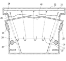
また、グリル庫22天井には、図2に示すように、グリル庫22内の上バーナ26より上段で左右のバーナ間の中央に、先端を下方へ向けると共に、バーナ方向へ傾斜面を向けた断面V字状の排気ガイド部48及び分布板48aがグリル庫22内に突き出るように設けられる。この排気ガイド部48及び分布板48aは、グリル庫22下方の被調理物Fが均一に加熱されるように燃焼廃ガスを導く目的で設けられる。このため、グリル庫22の大きさ、ガス消費量、上バーナ26の傾き、連通口38の位置と大きさとにより、排気ガイド部48の傾斜面高さと角度とが適切に設定される。
【0020】
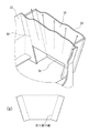
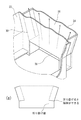
そして、図3及び図4に示すように、排気室36は、その排気断面積が上方に向かうにつれて漸次広くなる逆台形状になるように、排気ダクト34により形成され、排気ダクト34上部には従来例と同じ幅のフレームトラップ33を有する排気口32が形成される。隔壁30には、排気室36に連通する連通口38が排気ダクト34の左右側面壁の形状に沿うように、連通口38がその上端幅が下端幅より長い逆台形状に形成されている。この場合、図5に示すような、連通口38の形状を従来例と同様に上端幅と下端幅が同じ長さの長方形に形成し、排気室36を構成する排気ダクト34の下部ををその長方形の連通口38の形状にあわせて形成する構造のものが考えられるが、図6の排気ダクト34を一枚板から折曲加工のみで製作するのは、その展開図である図6(a)の如く不可能である。しかし、図4に示すような構成であれば、排気ダクト34の展開図である図4(a)のように一枚板から折曲加工のみで製作できる。
【0021】
尚、図3及び図4に示される連通口38は、上端に向かって漸次広くなる逆台形状に形成されているので、その連通口38の下端幅が従来例のものよりも狭くなるが、グリル庫22上部にたまって、連通口38へあふれ出る燃焼廃ガスや被調理物から発生する煙等の排気の流れは、そのほとんどが連通口38の広くなった上端部付近に集中して形成されるので、よりスムーズに排出される。
【0022】
次に、燃焼廃ガス及び排気の流れについて説明する。まず、点火操作により、左右側方の上バーナ26から噴出される燃料ガスに点火されて燃焼が開始されると、高温の燃焼廃ガスはグリル庫22上部に溜まり、下方の連通口38へあふれて排気室36へ流入し、ドラフト効果により排気室36内を上昇して排出される。燃焼がこのまま続けられると、図2に示すように燃焼廃ガスは、そのドラフト力と燃料ガスの噴出力とによって中央上方部に向けて流れ、断面V字状の排気ガイド部48及び分布板48aに沿って上方から下方の被調理物F方向へ流れる。
【0023】
この場合に、燃焼廃ガスの流れの方向が排気ガイド部48の傾斜面により下方に導かれ、傾斜面から離れている部分の燃焼廃ガスもこの流れに導かれて下方に流れる。このため、燃焼廃ガスは被調理物F全体へ均一な流れとなり、燃焼廃ガスに接触する被調理物Fは均一に加熱される。このように、被調理物Fは、上バーナ26の輻射熱によらないで、充満して均一に対流する高温の燃焼廃ガスに包まれ、また被調理物Fの下面は下バーナ27の燃焼熱で加熱調理される。
【0024】
上バーナ26は、燃焼に必要な空気全てを1次空気として供給する全1次空気式バーナであるので、グリル庫22が燃焼廃ガスで充満しても良好な燃焼を維持する。また、上バーナ26は上方向に傾斜されているため、被調理物F、受皿28に溜まった焼き脂への輻射加熱は弱くなる。しかも、同時に、排気室36のドラフト効果によりグリル庫の手前の隙間47から外部の新鮮な空気が吸引され、受皿28を冷却して後方の連通口38から排出されるため、受皿28に水を入れなくても受皿28上に落下した被調理物Fの焼き脂が過熱によって発火しない。
【0025】
このとき、排気口32の幅が従来と同じであるにもかかわらず、排気室36は排気ダクト34によって排気断面積が上方に向かうにつれて漸次広くなる逆台形状に形成されているので、排気室36を上昇する燃焼廃ガスや被調理物Fから発生する煙等の排気が排気室38内に滞留することなく排気上流側より排気下流側に向かって流出する。従って、排気のドラフト力をより効果的に得ることができ、抵抗の少ない円滑な排出が可能になる。
【0026】
このように、ガスバーナの燃焼廃ガスによる対流熱がグリル庫22内にこもって、被調理物の加熱に十分に供された後、連通口38から排気室36にあふれた燃焼廃ガスや被調理物Fから発生する煙等がスムーズにグリル庫外へ排出されるので、安定した燃焼を行なうことができ、さらに燃焼廃ガスに接触する被調理物Fはグリル庫内に充満して対流する高温の燃焼廃ガスに包まれて加熱調理されるので、良好に加熱調理され、被調理物Fの加熱効率が向上する。しかも、そのスムーズな排気の流れによりグリル庫の手前の隙間47及びギャラリ47aから外部の新鮮な空気の吸引が促進され、受皿28を冷却して後方の連通口38から排出されるので、受皿28の冷却効果が向上し受皿28上に落下した被調理物Fの焼き脂が過熱が防止され、さらには下バーナ27の燃焼に必要な二次空気としての利用も促進される。
【0027】
以上本発明の実施例について説明したが、本発明はこうした実施例に何ら限定されるものではなく、本発明の要旨を逸脱しない範囲において、種々なる態様で実施することは勿論である。要するに排気室を形成する排気ダクトが上方に向かって漸次拡径状に形成されていれば良く、実施例では排気室の手前側の隔壁および後側の後壁を垂直に立設するようにしたが、それぞれ同方向または異方向に傾斜させても実施可能であるし、排気ダクト断面の形状も円形または楕円形でも良い。
【0028】
【発明の効果】
本発明の請求項1に係るグリル庫の排気構造によれば、グリル庫内でガスバーナの燃焼廃ガスにより焼網上の被調理物が加熱調理され、その燃焼廃ガスや被調理物から発生する煙等は連通口より排気ダクトへ導かれて、グリル庫外へ排出されるが、そのとき、その排気ダクトは上方に向かって漸次拡径状に形成されているので、排気の流れが滞ることなく少ない抵抗でスムーズに排気される。そのためにガスバーナの燃焼性の改善に大きく貢献することになり、より安定した燃焼を行なうことが可能となって、効率的に被調理物を加熱調理することができることになり、特に前述の火炎の伝播を阻止して消炎させるフレームトラップを排気口に備えたときはその作用効果がより大きなものとなる。このとき、連通口38がその上端幅が下端幅より長い逆台形状に形成されることにより、排気室を構成する排気ダクトを一の部材、例えば一枚の金属板を屈曲加工することで簡易で安価に製作できる。
【0029】
また、グリル庫内の奥行部の隔壁に開設される連通口が焼網に載置される被調理物よりも下方に設けられているため、ガスバーナの燃焼廃ガスによる対流熱がグリル庫内にこもって、被調理物の加熱に十分に供された後、連通口から排気室にあふれた燃焼廃ガスや被調理物から発生する煙等が抵抗なくスムーズに排気室を上昇してグリル庫外へ排出されるので、グリル庫の手前の隙間から外部の新鮮な空気が、受皿を冷却するのに十分吸引されると共に、グリル庫内に高温の燃焼廃ガスがこもり過ぎないので、受皿に溜まった焼き脂等の過熱による発火が防止できる。さらにブンゼン式の下バーナを備えた場合には、燃焼に必要な二次空気の導入も促進され、その燃焼性をも改善されることになる。
【0030】
さらに、排気ダクトはグリル庫の幅方向に漸次拡径となる逆台形状に形成されているため、幅方向のスペースを利用することにより、奥行方向のスペースを犠牲にすることなく排気ダクトを漸次拡径状に形成することができ、さらには下バーナ等の配設を制限することなく、その簡易な構造により安価なコストで製造できるので経済的である。
【図面の簡単な説明】
【図1】本発明の一実施形態に係る調理用グリルの奥行方向の断面図である。
【図2】本発明の一実施形態に係る図1に示した調理用グリルのA−A断面図である。
【図3】本発明の一実施形態に係る図1に示した調理用グリルのB−B断面図である。
【図4】図3に示した排気ダクトの斜視図である。
【図5】本発明の他の実施形態に係る図1に示した調理用グリルのB−B断面図である。
【図6】図5に示した排気ダクトの斜視図である。
【図7】従来例に係る調理用グリルの排気構造を示した図である。
【図8】他の従来例に係る調理用グリルの排気構造を示した図である。
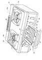
【図9】従来一般に知られる調理用グリルを備えたテーブルコンロの外観斜視図である。
【符号の説明】
20 調理用グリル
22 グリル庫
26 上バーナ
27 下バーナ
30 隔壁
32 開口部
34 排気ダクト
36 排気室
38 連通口[0001]
BACKGROUND OF THE INVENTION
TECHNICAL FIELD The present invention relates to a cooking grill for cooking a cooking object such as fish by a gas burner on a grill net in a grill warehouse, and more particularly, combustion waste gas that is used to heat the cooking object and fills the grill warehouse. The present invention relates to an exhaust structure of a grill cabinet that reduces the resistance of an exhaust flow from an exhaust duct such as smoke generated from an object to be cooked.
[0002]
[Prior art]
2. Description of the Related Art Conventionally, table cookers are known that incorporate a cooking grill that heats cooked food such as fish in a grill cabinet. As shown in FIG. 1, such a grill for cooking includes a
[0003]
With such a configuration, the combustion waste gas in the
[0004]
In such a cooking grill, after the combustion waste gas of the gas burner is sufficiently trapped in the
[0005]
This shows a BB cross section of FIG. 1, and the
[0006]
[Problems to be solved by the invention]
However, in such a grill for double-sided baking cooking using an oven-type heating structure using a natural exhaust system, after high-temperature combustion waste gas is sufficiently stored in the
[0007]
Further, if the high-temperature combustion waste gas is excessively accumulated in the
[0008]
The problem to be solved by the present invention is that, in this type of cooking grill, resistance of exhaust flow such as combustion waste gas of the gas burner used for heating the cooking object in the grill and smoke generated from the cooking object It is an object to provide an exhaust structure of a grille that can reduce the amount of heat and ensure good combustibility. Another object of the present invention is to manufacture a single plate at low cost only by bending to form an exhaust duct.
[0009]
[Means for Solving the Problems]
In order to solve this problem, the exhaust structure of the grill warehouse according to the present invention is provided with a gas burner for heating and cooking an object to be cooked placed on a grill net, and a combustion waste gas of the gas burner. And an exhaust duct that discharges smoke generated from the food to be cooked is provided through a communication port established in a partition wall in the depth part of the grill cabinet, and the communication port is placed on the grill net to be cooked The exhaust duct is formed in an inverted trapezoidal shape whose upper end width is longer than the lower end width , and the exhaust duct is gradually reversed in the width direction of the grill box upward by bending a single plate. The gist is that it is formed in a trapezoidal shape .
[0010]
According to the exhaust structure of the grill warehouse according to
[0011]
Further, since the communication port is opened in the depth portion of the partition wall in the grill box is provided below the food placed on the baked net, convective heat within the grill chamber by the combustion waste gas of the gas burner Thus, after the cooking object is sufficiently heated, the combustion exhaust gas overflowing from the communication port to the exhaust chamber, the smoke generated from the cooking object, and the like are smoothly discharged out of the grill.
[0012]
Furthermore, since the exhaust duct is formed in an inverted trapezoidal shape which is gradually diverging in the width direction of the grill box, by utilizing a space in the width direction, without sacrificing space in the depth direction, a burner, etc. The exhaust duct can be formed in a gradually expanded diameter with a simple configuration without affecting the arrangement of
[0013]
DETAILED DESCRIPTION OF THE INVENTION
Hereinafter, an embodiment of the present invention will be described in detail with reference to the drawings. FIG. 9 shows an example in which the cooking grill according to one embodiment of the present invention is applied to a table stove. As shown in the figure, this
[0014]
A
[0015]
As shown in FIG. 1, a surface combustion type
[0016]
And in the depth part of this grill |
[0017]
At the front center of the
[0018]
The
[0019]
Further, as shown in FIG. 2, the top of the
[0020]
As shown in FIGS. 3 and 4, the
[0021]
The
[0022]
Next, the flow of combustion waste gas and exhaust will be described. First, when ignition is performed on the fuel gas ejected from the left and right
[0023]
In this case, the flow direction of the combustion waste gas is guided downward by the inclined surface of the
[0024]
Since the
[0025]
At this time, although the width of the
[0026]
Thus, after the convection heat by the combustion waste gas of the gas burner is confined in the
[0027]
As mentioned above, although the Example of this invention was described, this invention is not limited to such an Example at all, Of course, it implements in a various aspect in the range which does not deviate from the summary of this invention. In short, it is only necessary that the exhaust duct forming the exhaust chamber is gradually increased in diameter upward, and in the embodiment, the front partition wall and the rear rear wall of the exhaust chamber are erected vertically. However, it can also be implemented by inclining in the same direction or different directions, and the shape of the cross section of the exhaust duct may be circular or elliptical.
[0028]
【The invention's effect】
According to the exhaust structure of the grill cabinet according to
[0029]
Further, since the communication port is opened in the depth portion of the partition wall in the grill box is provided below the food placed on the baked net, convective heat within the grill chamber by the combustion waste gas of the gas burner After being fully heated to the cooking object, the combustion exhaust gas overflowing from the communication port to the exhaust chamber and the smoke generated from the cooking object rise smoothly and without resistance to the outside of the grill. As the outside fresh air is sufficiently sucked from the gap in front of the grill cabinet to cool the tray, and the high temperature combustion waste gas does not accumulate in the grill cabinet, it accumulates in the tray. Can prevent ignition due to overheating of baked fat. Further, when a Bunsen type lower burner is provided, the introduction of secondary air necessary for combustion is also promoted, and its combustibility is also improved.
[0030]
Furthermore, since the exhaust duct is formed in an inverted trapezoidal shape which is gradually diverging in the width direction of the grill box, by utilizing a space in the width direction, the exhaust duct without sacrificing space in the depth direction gradually It is economical because it can be formed in an expanded shape and can be manufactured at a low cost with its simple structure without restricting the arrangement of the lower burner and the like.
[Brief description of the drawings]
FIG. 1 is a sectional view in a depth direction of a cooking grill according to an embodiment of the present invention.
2 is a cross-sectional view taken along line AA of the cooking grill shown in FIG. 1 according to an embodiment of the present invention.
3 is a BB cross-sectional view of the cooking grill shown in FIG. 1 according to one embodiment of the present invention.
4 is a perspective view of the exhaust duct shown in FIG. 3. FIG.
5 is a BB cross-sectional view of the cooking grill shown in FIG. 1 according to another embodiment of the present invention.
6 is a perspective view of the exhaust duct shown in FIG. 5. FIG.
FIG. 7 is a view showing an exhaust structure of a cooking grill according to a conventional example.
FIG. 8 is a view showing an exhaust structure of a cooking grill according to another conventional example.
FIG. 9 is an external perspective view of a table stove provided with a cooking grill that is generally known conventionally.
[Explanation of symbols]
20 Grill for
Claims (1)
Priority Applications (1)
| Application Number | Priority Date | Filing Date | Title |
|---|---|---|---|
| JP2000134143A JP4262860B2 (en) | 2000-05-08 | 2000-05-08 | Exhaust structure of grill storage |
Applications Claiming Priority (1)
| Application Number | Priority Date | Filing Date | Title |
|---|---|---|---|
| JP2000134143A JP4262860B2 (en) | 2000-05-08 | 2000-05-08 | Exhaust structure of grill storage |
Publications (2)
| Publication Number | Publication Date |
|---|---|
| JP2001314329A JP2001314329A (en) | 2001-11-13 |
| JP4262860B2 true JP4262860B2 (en) | 2009-05-13 |
Family
ID=18642474
Family Applications (1)
| Application Number | Title | Priority Date | Filing Date |
|---|---|---|---|
| JP2000134143A Expired - Fee Related JP4262860B2 (en) | 2000-05-08 | 2000-05-08 | Exhaust structure of grill storage |
Country Status (1)
| Country | Link |
|---|---|
| JP (1) | JP4262860B2 (en) |
Families Citing this family (2)
| Publication number | Priority date | Publication date | Assignee | Title |
|---|---|---|---|---|
| JP4677576B2 (en) * | 2005-04-26 | 2011-04-27 | 株式会社パロマ | Gas grill |
| JP6219804B2 (en) * | 2014-11-10 | 2017-10-25 | ホシザキ株式会社 | Flyer |
-
2000
- 2000-05-08 JP JP2000134143A patent/JP4262860B2/en not_active Expired - Fee Related
Also Published As
| Publication number | Publication date |
|---|---|
| JP2001314329A (en) | 2001-11-13 |
Similar Documents
| Publication | Publication Date | Title |
|---|---|---|
| JP4279824B2 (en) | Grill burner | |
| JP4262860B2 (en) | Exhaust structure of grill storage | |
| JP2001324153A (en) | Structure for preventing top plate temperature increase | |
| KR200459206Y1 (en) | Grill of gas range | |
| JP2003070656A (en) | Built-in stove | |
| JP4203178B2 (en) | grill | |
| JP3661719B2 (en) | Gas grill | |
| JP4375770B2 (en) | grill | |
| JP2000245624A (en) | Gas grill | |
| JPH1078227A (en) | Gas grill | |
| JP2000232945A (en) | Both-side roasting grill | |
| JP7265937B2 (en) | heating cooker | |
| JP3005845B2 (en) | Exhaust structure of grill storage | |
| JP4132404B2 (en) | grill | |
| JP2000217718A (en) | Double-sided grill | |
| JP6927789B2 (en) | grill | |
| JP4132447B2 (en) | Double-sided grill | |
| JP3814402B2 (en) | Double-sided grill | |
| JP3780393B2 (en) | grill | |
| JP3218233B2 (en) | Gas grill | |
| JP3747310B2 (en) | Gas grill | |
| JP3780400B2 (en) | Gas grill | |
| JPH04347113A (en) | Gas cooker | |
| JP3953204B2 (en) | Gas grill | |
| JP2000111052A (en) | Gas grill |
Legal Events
| Date | Code | Title | Description |
|---|---|---|---|
| A621 | Written request for application examination |
Free format text: JAPANESE INTERMEDIATE CODE: A621 Effective date: 20070424 |
|
| A977 | Report on retrieval |
Free format text: JAPANESE INTERMEDIATE CODE: A971007 Effective date: 20080527 |
|
| A131 | Notification of reasons for refusal |
Free format text: JAPANESE INTERMEDIATE CODE: A131 Effective date: 20080603 |
|
| A521 | Written amendment |
Free format text: JAPANESE INTERMEDIATE CODE: A523 Effective date: 20080722 |
|
| A131 | Notification of reasons for refusal |
Free format text: JAPANESE INTERMEDIATE CODE: A131 Effective date: 20080924 |
|
| A521 | Written amendment |
Free format text: JAPANESE INTERMEDIATE CODE: A523 Effective date: 20081107 |
|
| TRDD | Decision of grant or rejection written | ||
| A01 | Written decision to grant a patent or to grant a registration (utility model) |
Free format text: JAPANESE INTERMEDIATE CODE: A01 Effective date: 20090120 |
|
| A01 | Written decision to grant a patent or to grant a registration (utility model) |
Free format text: JAPANESE INTERMEDIATE CODE: A01 |
|
| A61 | First payment of annual fees (during grant procedure) |
Free format text: JAPANESE INTERMEDIATE CODE: A61 Effective date: 20090210 |
|
| FPAY | Renewal fee payment (event date is renewal date of database) |
Free format text: PAYMENT UNTIL: 20120220 Year of fee payment: 3 |
|
| R150 | Certificate of patent or registration of utility model |
Ref document number: 4262860 Country of ref document: JP Free format text: JAPANESE INTERMEDIATE CODE: R150 Free format text: JAPANESE INTERMEDIATE CODE: R150 |
|
| FPAY | Renewal fee payment (event date is renewal date of database) |
Free format text: PAYMENT UNTIL: 20120220 Year of fee payment: 3 |
|
| FPAY | Renewal fee payment (event date is renewal date of database) |
Free format text: PAYMENT UNTIL: 20120220 Year of fee payment: 3 |
|
| FPAY | Renewal fee payment (event date is renewal date of database) |
Free format text: PAYMENT UNTIL: 20120220 Year of fee payment: 3 |
|
| FPAY | Renewal fee payment (event date is renewal date of database) |
Free format text: PAYMENT UNTIL: 20120220 Year of fee payment: 3 |
|
| S533 | Written request for registration of change of name |
Free format text: JAPANESE INTERMEDIATE CODE: R313533 |
|
| FPAY | Renewal fee payment (event date is renewal date of database) |
Free format text: PAYMENT UNTIL: 20120220 Year of fee payment: 3 |
|
| R350 | Written notification of registration of transfer |
Free format text: JAPANESE INTERMEDIATE CODE: R350 |
|
| FPAY | Renewal fee payment (event date is renewal date of database) |
Free format text: PAYMENT UNTIL: 20150220 Year of fee payment: 6 |
|
| R250 | Receipt of annual fees |
Free format text: JAPANESE INTERMEDIATE CODE: R250 |
|
| R250 | Receipt of annual fees |
Free format text: JAPANESE INTERMEDIATE CODE: R250 |
|
| R250 | Receipt of annual fees |
Free format text: JAPANESE INTERMEDIATE CODE: R250 |
|
| LAPS | Cancellation because of no payment of annual fees |