JP4262780B2 - Inclined metal parts for electrochemical cells - Google Patents
Inclined metal parts for electrochemical cells Download PDFInfo
- Publication number
- JP4262780B2 JP4262780B2 JP53969498A JP53969498A JP4262780B2 JP 4262780 B2 JP4262780 B2 JP 4262780B2 JP 53969498 A JP53969498 A JP 53969498A JP 53969498 A JP53969498 A JP 53969498A JP 4262780 B2 JP4262780 B2 JP 4262780B2
- Authority
- JP
- Japan
- Prior art keywords
- substrate
- metal
- applying
- surface layer
- metal member
- Prior art date
- Legal status (The legal status is an assumption and is not a legal conclusion. Google has not performed a legal analysis and makes no representation as to the accuracy of the status listed.)
- Expired - Fee Related
Links
Images


Classifications
-
- C—CHEMISTRY; METALLURGY
- C23—COATING METALLIC MATERIAL; COATING MATERIAL WITH METALLIC MATERIAL; CHEMICAL SURFACE TREATMENT; DIFFUSION TREATMENT OF METALLIC MATERIAL; COATING BY VACUUM EVAPORATION, BY SPUTTERING, BY ION IMPLANTATION OR BY CHEMICAL VAPOUR DEPOSITION, IN GENERAL; INHIBITING CORROSION OF METALLIC MATERIAL OR INCRUSTATION IN GENERAL
- C23C—COATING METALLIC MATERIAL; COATING MATERIAL WITH METALLIC MATERIAL; SURFACE TREATMENT OF METALLIC MATERIAL BY DIFFUSION INTO THE SURFACE, BY CHEMICAL CONVERSION OR SUBSTITUTION; COATING BY VACUUM EVAPORATION, BY SPUTTERING, BY ION IMPLANTATION OR BY CHEMICAL VAPOUR DEPOSITION, IN GENERAL
- C23C28/00—Coating for obtaining at least two superposed coatings either by methods not provided for in a single one of groups C23C2/00 - C23C26/00 or by combinations of methods provided for in subclasses C23C and C25C or C25D
- C23C28/02—Coating for obtaining at least two superposed coatings either by methods not provided for in a single one of groups C23C2/00 - C23C26/00 or by combinations of methods provided for in subclasses C23C and C25C or C25D only coatings only including layers of metallic material
- C23C28/023—Coating for obtaining at least two superposed coatings either by methods not provided for in a single one of groups C23C2/00 - C23C26/00 or by combinations of methods provided for in subclasses C23C and C25C or C25D only coatings only including layers of metallic material only coatings of metal elements only
-
- C—CHEMISTRY; METALLURGY
- C23—COATING METALLIC MATERIAL; COATING MATERIAL WITH METALLIC MATERIAL; CHEMICAL SURFACE TREATMENT; DIFFUSION TREATMENT OF METALLIC MATERIAL; COATING BY VACUUM EVAPORATION, BY SPUTTERING, BY ION IMPLANTATION OR BY CHEMICAL VAPOUR DEPOSITION, IN GENERAL; INHIBITING CORROSION OF METALLIC MATERIAL OR INCRUSTATION IN GENERAL
- C23C—COATING METALLIC MATERIAL; COATING MATERIAL WITH METALLIC MATERIAL; SURFACE TREATMENT OF METALLIC MATERIAL BY DIFFUSION INTO THE SURFACE, BY CHEMICAL CONVERSION OR SUBSTITUTION; COATING BY VACUUM EVAPORATION, BY SPUTTERING, BY ION IMPLANTATION OR BY CHEMICAL VAPOUR DEPOSITION, IN GENERAL
- C23C26/00—Coating not provided for in groups C23C2/00 - C23C24/00
-
- C—CHEMISTRY; METALLURGY
- C23—COATING METALLIC MATERIAL; COATING MATERIAL WITH METALLIC MATERIAL; CHEMICAL SURFACE TREATMENT; DIFFUSION TREATMENT OF METALLIC MATERIAL; COATING BY VACUUM EVAPORATION, BY SPUTTERING, BY ION IMPLANTATION OR BY CHEMICAL VAPOUR DEPOSITION, IN GENERAL; INHIBITING CORROSION OF METALLIC MATERIAL OR INCRUSTATION IN GENERAL
- C23C—COATING METALLIC MATERIAL; COATING MATERIAL WITH METALLIC MATERIAL; SURFACE TREATMENT OF METALLIC MATERIAL BY DIFFUSION INTO THE SURFACE, BY CHEMICAL CONVERSION OR SUBSTITUTION; COATING BY VACUUM EVAPORATION, BY SPUTTERING, BY ION IMPLANTATION OR BY CHEMICAL VAPOUR DEPOSITION, IN GENERAL
- C23C28/00—Coating for obtaining at least two superposed coatings either by methods not provided for in a single one of groups C23C2/00 - C23C26/00 or by combinations of methods provided for in subclasses C23C and C25C or C25D
- C23C28/02—Coating for obtaining at least two superposed coatings either by methods not provided for in a single one of groups C23C2/00 - C23C26/00 or by combinations of methods provided for in subclasses C23C and C25C or C25D only coatings only including layers of metallic material
- C23C28/021—Coating for obtaining at least two superposed coatings either by methods not provided for in a single one of groups C23C2/00 - C23C26/00 or by combinations of methods provided for in subclasses C23C and C25C or C25D only coatings only including layers of metallic material including at least one metal alloy layer
-
- C—CHEMISTRY; METALLURGY
- C23—COATING METALLIC MATERIAL; COATING MATERIAL WITH METALLIC MATERIAL; CHEMICAL SURFACE TREATMENT; DIFFUSION TREATMENT OF METALLIC MATERIAL; COATING BY VACUUM EVAPORATION, BY SPUTTERING, BY ION IMPLANTATION OR BY CHEMICAL VAPOUR DEPOSITION, IN GENERAL; INHIBITING CORROSION OF METALLIC MATERIAL OR INCRUSTATION IN GENERAL
- C23C—COATING METALLIC MATERIAL; COATING MATERIAL WITH METALLIC MATERIAL; SURFACE TREATMENT OF METALLIC MATERIAL BY DIFFUSION INTO THE SURFACE, BY CHEMICAL CONVERSION OR SUBSTITUTION; COATING BY VACUUM EVAPORATION, BY SPUTTERING, BY ION IMPLANTATION OR BY CHEMICAL VAPOUR DEPOSITION, IN GENERAL
- C23C28/00—Coating for obtaining at least two superposed coatings either by methods not provided for in a single one of groups C23C2/00 - C23C26/00 or by combinations of methods provided for in subclasses C23C and C25C or C25D
- C23C28/02—Coating for obtaining at least two superposed coatings either by methods not provided for in a single one of groups C23C2/00 - C23C26/00 or by combinations of methods provided for in subclasses C23C and C25C or C25D only coatings only including layers of metallic material
- C23C28/028—Including graded layers in composition or in physical properties, e.g. density, porosity, grain size
-
- C—CHEMISTRY; METALLURGY
- C25—ELECTROLYTIC OR ELECTROPHORETIC PROCESSES; APPARATUS THEREFOR
- C25B—ELECTROLYTIC OR ELECTROPHORETIC PROCESSES FOR THE PRODUCTION OF COMPOUNDS OR NON-METALS; APPARATUS THEREFOR
- C25B9/00—Cells or assemblies of cells; Constructional parts of cells; Assemblies of constructional parts, e.g. electrode-diaphragm assemblies; Process-related cell features
-
- C—CHEMISTRY; METALLURGY
- C25—ELECTROLYTIC OR ELECTROPHORETIC PROCESSES; APPARATUS THEREFOR
- C25D—PROCESSES FOR THE ELECTROLYTIC OR ELECTROPHORETIC PRODUCTION OF COATINGS; ELECTROFORMING; APPARATUS THEREFOR
- C25D3/00—Electroplating: Baths therefor
- C25D3/02—Electroplating: Baths therefor from solutions
- C25D3/48—Electroplating: Baths therefor from solutions of gold
-
- C—CHEMISTRY; METALLURGY
- C25—ELECTROLYTIC OR ELECTROPHORETIC PROCESSES; APPARATUS THEREFOR
- C25D—PROCESSES FOR THE ELECTROLYTIC OR ELECTROPHORETIC PRODUCTION OF COATINGS; ELECTROFORMING; APPARATUS THEREFOR
- C25D3/00—Electroplating: Baths therefor
- C25D3/02—Electroplating: Baths therefor from solutions
- C25D3/56—Electroplating: Baths therefor from solutions of alloys
- C25D3/62—Electroplating: Baths therefor from solutions of alloys containing more than 50% by weight of gold
-
- C—CHEMISTRY; METALLURGY
- C25—ELECTROLYTIC OR ELECTROPHORETIC PROCESSES; APPARATUS THEREFOR
- C25D—PROCESSES FOR THE ELECTROLYTIC OR ELECTROPHORETIC PRODUCTION OF COATINGS; ELECTROFORMING; APPARATUS THEREFOR
- C25D5/00—Electroplating characterised by the process; Pretreatment or after-treatment of workpieces
- C25D5/10—Electroplating with more than one layer of the same or of different metals
-
- C—CHEMISTRY; METALLURGY
- C25—ELECTROLYTIC OR ELECTROPHORETIC PROCESSES; APPARATUS THEREFOR
- C25D—PROCESSES FOR THE ELECTROLYTIC OR ELECTROPHORETIC PRODUCTION OF COATINGS; ELECTROFORMING; APPARATUS THEREFOR
- C25D5/00—Electroplating characterised by the process; Pretreatment or after-treatment of workpieces
- C25D5/48—After-treatment of electroplated surfaces
- C25D5/50—After-treatment of electroplated surfaces by heat-treatment
-
- H—ELECTRICITY
- H01—ELECTRIC ELEMENTS
- H01M—PROCESSES OR MEANS, e.g. BATTERIES, FOR THE DIRECT CONVERSION OF CHEMICAL ENERGY INTO ELECTRICAL ENERGY
- H01M8/00—Fuel cells; Manufacture thereof
- H01M8/02—Details
- H01M8/0202—Collectors; Separators, e.g. bipolar separators; Interconnectors
- H01M8/0204—Non-porous and characterised by the material
- H01M8/0206—Metals or alloys
-
- H—ELECTRICITY
- H01—ELECTRIC ELEMENTS
- H01M—PROCESSES OR MEANS, e.g. BATTERIES, FOR THE DIRECT CONVERSION OF CHEMICAL ENERGY INTO ELECTRICAL ENERGY
- H01M2300/00—Electrolytes
- H01M2300/0017—Non-aqueous electrolytes
- H01M2300/0065—Solid electrolytes
- H01M2300/0082—Organic polymers
-
- H—ELECTRICITY
- H01—ELECTRIC ELEMENTS
- H01M—PROCESSES OR MEANS, e.g. BATTERIES, FOR THE DIRECT CONVERSION OF CHEMICAL ENERGY INTO ELECTRICAL ENERGY
- H01M8/00—Fuel cells; Manufacture thereof
- H01M8/02—Details
- H01M8/0202—Collectors; Separators, e.g. bipolar separators; Interconnectors
- H01M8/0204—Non-porous and characterised by the material
- H01M8/0223—Composites
- H01M8/0228—Composites in the form of layered or coated products
-
- Y—GENERAL TAGGING OF NEW TECHNOLOGICAL DEVELOPMENTS; GENERAL TAGGING OF CROSS-SECTIONAL TECHNOLOGIES SPANNING OVER SEVERAL SECTIONS OF THE IPC; TECHNICAL SUBJECTS COVERED BY FORMER USPC CROSS-REFERENCE ART COLLECTIONS [XRACs] AND DIGESTS
- Y02—TECHNOLOGIES OR APPLICATIONS FOR MITIGATION OR ADAPTATION AGAINST CLIMATE CHANGE
- Y02E—REDUCTION OF GREENHOUSE GAS [GHG] EMISSIONS, RELATED TO ENERGY GENERATION, TRANSMISSION OR DISTRIBUTION
- Y02E60/00—Enabling technologies; Technologies with a potential or indirect contribution to GHG emissions mitigation
- Y02E60/30—Hydrogen technology
- Y02E60/36—Hydrogen production from non-carbon containing sources, e.g. by water electrolysis
-
- Y—GENERAL TAGGING OF NEW TECHNOLOGICAL DEVELOPMENTS; GENERAL TAGGING OF CROSS-SECTIONAL TECHNOLOGIES SPANNING OVER SEVERAL SECTIONS OF THE IPC; TECHNICAL SUBJECTS COVERED BY FORMER USPC CROSS-REFERENCE ART COLLECTIONS [XRACs] AND DIGESTS
- Y02—TECHNOLOGIES OR APPLICATIONS FOR MITIGATION OR ADAPTATION AGAINST CLIMATE CHANGE
- Y02E—REDUCTION OF GREENHOUSE GAS [GHG] EMISSIONS, RELATED TO ENERGY GENERATION, TRANSMISSION OR DISTRIBUTION
- Y02E60/00—Enabling technologies; Technologies with a potential or indirect contribution to GHG emissions mitigation
- Y02E60/30—Hydrogen technology
- Y02E60/50—Fuel cells
-
- Y—GENERAL TAGGING OF NEW TECHNOLOGICAL DEVELOPMENTS; GENERAL TAGGING OF CROSS-SECTIONAL TECHNOLOGIES SPANNING OVER SEVERAL SECTIONS OF THE IPC; TECHNICAL SUBJECTS COVERED BY FORMER USPC CROSS-REFERENCE ART COLLECTIONS [XRACs] AND DIGESTS
- Y02—TECHNOLOGIES OR APPLICATIONS FOR MITIGATION OR ADAPTATION AGAINST CLIMATE CHANGE
- Y02P—CLIMATE CHANGE MITIGATION TECHNOLOGIES IN THE PRODUCTION OR PROCESSING OF GOODS
- Y02P70/00—Climate change mitigation technologies in the production process for final industrial or consumer products
- Y02P70/50—Manufacturing or production processes characterised by the final manufactured product
Description
技術分野
本発明は、電解性物質用の電気化学電池スタックに関するものであり、特に、飛行機や宇宙船で使用するための水から酸素及び水素ガスを製造する高圧電気化学電池スタックに関するものである。
発明の背景
電気化学電池は、一般に水のような供給物流体から生成物ガスを生成するために用いられ、また「燃料電池」型の構成では、供給燃料から電気エネルギーを生成する。生成物ガスのよく知られた用途には、空気及び宇宙船用酸素ストレージ、エネルギー変換及び宇宙船推進用のガスストレージが含まれる。特定の用途の必要性を満たすために、通常複数の平坦な電気化学電池が、垂直方向に積層されたスタックとして配置される。このようなスタックでは、電池群が、スタックを機能的システムとして一体化するための共通の部材を有している。例えば、各電池は、流体の流入、処理、及びスタックからの流体の排出のための流体キャビティ及び流体通路を画定し;電気を伝え;及び電解液及びシール等のような電池構造の機械的支持体となる金属部材を有している。
水から酸素及び水素ガスを生成するために用いられる電気化学電池スタックは、様々な特殊かつ困難な要求を受ける。第1に、このような電気化学電池スタックの動作効率及びスタックによって生成されるガスの貯蔵効率は、内部動作圧力が高くなるほど上昇する。このため、内部動作圧力は、多くの場合約6000psiもの高い圧力まで高められる。従って、個々の電気化学電池の金属部材は、この大きな圧力差に確実に耐えられるものでなければならない。
第2に、最近の電気化学電池は、高い酸性の官能基を有している固体ポリマー電解質膜を使用していることが多い。供給物流体としての水を酸素及び水素ガスに電気分解する電池においてこのような膜が使用される場合、膜表面に接触する水溶液は高い酸性となる。従って、電池の金属部材の表面は、このような酸性水溶液に曝されたとき化学的に安定でなければならない。第3に、電気化学電池の動作時に電気が流れる電池の導電性金属部材は、陽極及び陰極分極にさらされる。第4に、水の電気分解により、高圧水素ガスが発生し、これは「水素ぜい性」としてよく知られたプロセスにより多くの金属を劣化させる。従って、金属部材を形成するために用いられる材料は、前述した圧力差、低いpH、陽極または陰極分極、及び水素ぜい性問題に曝された時に満足できる程度の化学的安定性と機械的強度を示さなければならない。例えば、多くのステンレス鋼は満足できる機械的強度特性を示すが、残念ながら陽極分極及び酸性溶液に暴露された状態のもとでは、ステンレス鋼は許容され得ない溶解度で溶解し、従って電気化学電池の金属部材を構成するための満足できる材料にはなり得ない。
このような電池の金属部材に対する第5の要求は、この金属部材が個々の電池の組立、電池の電気化学スタックへの組立、及びスタックの動作時での加工や動作によって生ずる応力に耐えられるだけの十分な硬さを有していることである。通常、この金属部材は、部材間を通る流体通路を画定し、従って極めて高い動作圧力において流体が通路から不適切に排出することを規制するべく平滑なシール面を有していなければならない。このような電気化学スタックの組立てでは、通常複数のナット、ボルト、ワッシャ等が用いられ、これらは電池の周りに取り付けられて、十分な予圧シールとなるように端部プレート間を貫通しており、また、様々なダクト、配管、調節弁、及び測定装置も同様にスタックにあるいはその内部に固定されなければならない。
スタック内のこのようなシールの完全性の維持は、協働して内部動作圧力に対抗する周知の圧縮部材によって達成される。一方同じ圧縮部材が、電池及び各電池の特定の金属部材を通しての一様で連続的な電流の流れを確保する。このような電池スタックの金属部材を通しての電流の導通状態及び均一な電流分布は、隣接する金属部材の金属−金属間接触によって達成される。圧縮部材は、最大6000psiである内部動作圧力より大きい、それに対抗する圧縮負荷を電池アセンブリの全面積に亘って維持し、これによって電池の機械的な完全性及び適切な電流の流れを確保する。上述した5種の特定の動作及び組立て時における要求があるため、たいていの金属部材は、例えばニオブ、ジリコニウム、チタンもしくはそれらの合金のような、化学的に安定で機械的に強度が高く、且つ硬い表面を有する特定の金属で作られる。電気化学電池スタックが、例えば潜水艦や宇宙船のような限定された製品の用途において用いられる場合には、このような特殊な金属材料の要求が、大きなコスト上の問題にはならない。
しかし、最近になって、民間航空機にて酸素ガスを生成するという目的で電気化学電池スタックを使用する必要性が生じてきた。例えば、高い高度において予期しない圧力低下が生じた場合のような非常時に、乗客に酸素を供給するために酸素マスクが自動的に準備される。通常この酸素は航空機内で金属のボトルに保存されており、その航空機が使用されている間、このボトルは定期的に充填される。航空機に積まれた電気化学電池スタックは、ボトルを充填するために用いることができ、これによって時間が節約され、地上でのサービスにかかるコストが低下する。また、このような電池スタックは、他の様々な状況においても酸素を供給することができる。しかし、既存の電気化学電池スタックは、前述のような特殊金属製の金属部材を使用しており、このような特殊金属の法外なコストのために、民間の航空機上での酸素生成の要求を満たすためにこれを使用できる可能性が制約されてしまう。
第2の金属表面層をめっき又は被覆された第1金属基板を有する既存のバイメタルは、金属部材としての用いるのは表面の硬さが足りない。このようなバイメタルは、化学的な安定性、電気伝導性、または外見上の問題を解決するべく選択された材料を塗布された表面層を有するからである。一般にバイメタルを用いる目的は、チタンのような基板にプラチナ群の金属のような表面層を被覆して電気分解による電極の溶解に対抗する化学的安定性を強化することによって、電池の電極の寿命を延ばすためである。このようなバイメタルを、上述の高圧電気化学電池の金属部材として実用的な使用に供するのは困難である。このような電池における機械的強度、化学的安定性、及び表面硬さについての厳しい要求のためである。例えば、バイメタル共通の問題点は、表面層と基板との間の境界層の耐久性である。十分なシール等のために必要な電気化学電池の通常の機械的応力の存在の下、特に電気的な導通状態及び均一な電流分布が隣接する金属部材間の金属−金属接続部を通しての導通状態によって決まる場合、基板と表面層との間の境界の遮断は、非効率的な電池動作につながり、更にはこのような動作環境での基板の化学的な不安定性を主な原因とする電池の破壊につながる。既存のバイメタルは、電気化学電池スタックの金属部材の厳しい要求を満たすように設計されてはいないことから、このバイメタルでは、表面層と基板との間の境界の許容されない遮断を生じさせることなくスタックの巨大な圧縮負荷を表面層から基板に伝達することができない。
従って、本発明の主な目的は、従来技術におけるコスト、機械的強度及び耐久性の欠如の問題を解決する、電気化学電池用の傾斜金属製金属部材を提供することである。
本発明の更に特定の目的は電池の動作条件において化学的に安定な電気化学電池用の傾斜金属製金属部材を提供することである。
本発明の別の特定の目的は、高圧動作条件に曝される電池構造の支持のための十分な機械的強度を有する、電気化学電池用の傾斜金属製金属部材を提供することである。
本発明の更に別の目的は、電池の組立時、及び電気化学電池スタックへの電池の組立時及びスタックの動作中において損傷を受けない十分な表面硬さを有する、電気化学電池用の傾斜金属製金属部材(graded metal hardware component)を提供することである。
本発明の更に別の目的は、表面層と基板との間の境界を遮断することなく電池の通常の圧縮負荷を表面層から基板へ伝達する、電気化学電池用の傾斜金属製金属部材を提供することである。
本発明のこれらの及び他の利点は、以下の発明の説明を添付の図面とともに参照した時に一層明らかとなろう。
発明の要約
固体ポリマー電解質膜を用いた高圧電気化学電池において電気化学電池構造体を機械的に支持し、流体の流入、電気分解処理及び流体の排出のための流体キャビティ及び通路を画定する、電気化学電池用傾斜金属製金属部品が開示される。特定の実施例では、この電気化学電池用傾斜金属製金属部材は、ステンレス鋼のような基板と、金のような貴金属性の表面層と、基板と表面層との間に隣接している傾斜境界層とを有する。傾斜境界層は、基板と表面層との相互拡散部を含み、傾斜境界層は、基板を構成する材料を0.5〜5.0重量%、表面層を構成する材料を99.5〜95.0重量%含み、且つ基板と表面層外面との間の最短距離の10〜90%の厚みを有する。好適実施例では、基板と表面層の外面との最短距離が50〜120マイクロインチであり、表面層の外面の硬度が、Knoop尺度で150〜200である。
傾斜金属製金属部材の好適な製造方法は、初めに基板に酸性の金(acid gold)の皮膜を塗布する過程と、次に一度被覆された基板に硬質の金の被膜(hard gold coating)を塗布する過程と、最後に2回被覆された基板を1〜24時間、200〜500℃の温度で加熱処理する過程とを含む。酸性の金及び硬質の金の被覆または被膜の塗布のための好適な方法は、電気めっきである。
初めに酸性の金で基板を被覆することにより、基板と金との間の接着性が高められる。次に効率の金で酸性の金を被覆し、被覆された基板を加熱処理することにより、得られた表面層が高圧電気化学電池の金属部材での要求を満たすに十分な硬さを示すとともに、表面と傾斜境界層が結合して、基板が酸性水溶液に曝された際に基板を陽極分極の悪影響からシールドされることになる。表面層の硬さによって、ひっかき傷やクラック等のような組立て時の応力によって表面層に損傷が生ずる可能性が最小限となり、且つ基板の酸性及び硬質の金の相互拡散によって形成された傾斜境界層によって、表面及び傾斜境界層の基板への接着性がかなり高められる。本発明の傾斜金属製金属部材により、低コストで必要な機械的強度を有する、ステンレス鋼のような比較的安価な基板を使用することが可能となり、且つ表面と傾斜境界層が結合して、固体ポリマー電解質膜を用いる高圧電気化学電池の金属部材に必要な硬い表面及び化学的安定性が得られる。
【図面の簡単な説明】
第1図は、本発明により構成された傾斜金属製金属部材を用いた電気化学電池の模式的な拡大図である。
第2図は、第1図の電気化学電池の傾斜金属製金属部材の平面図である。
第3図は、第2図の傾斜金属製金属部材の一部を示す、第2図の線3−3で切った拡大部分断面図である。
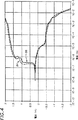
第4図は、本発明により構成された傾斜金属製金属部材の分極時の挙動を、基準となる金属部材と比較して示すグラフである。
好適実施例の詳細な説明
第2図及び第3図において、本発明の傾斜金属製金属部材が符号10を付して示されている。第1図に示すように、傾斜金属製金属部材のための適切な動作環境は、Titterington等に付与された、”High-Pressure Electrochemical Cell Structure”なる名称の米国特許第5,316,644号に記載されている電気化学電池のような電気化学電池である。上述の特許明細書はここで引用することにより本明細書と一体にされたものとする。当分野において良く知られているように、このような電気化学電池は、電気分解によって水を酸素及び水素ガスに分解するための電気分解電池12(第1図に模式的に示されているもの)であり得る。電気分解電池12は通常、固体ポリマー電解質膜18の両側に酸素(または”O2”)側アセンブリ14と水素(または”H2”)側アセンブリ12とを有し、これら全てが上側プレート20と下側プレート22との間にスタック状に(積層して)配置される。両プレートは、例えばボルト及びナット(図示せず)のような複数の固定要素と協働して電池12に圧縮力を与え、かつ他の電池(図示せず)とその電池とを位置合わせし、電気化学電池スタックを構成している。当分野において良く知られているように、各電池12は、例えば上側プレート20に隣接する絶縁体24や、絶縁体24と酸素側アセンブリ14との間のプラス端子26(或いは、下側プレート22と水素側アセンブリ16との間に位置しているプレートカバー28)のような、様々な共通の協働する機能的構造体も有している。
第1図に示されているように、電気分解電池12の酸素側アセンブリ14は、酸素側圧カパッド30と固体ポリマー電解質膜18との間に複数の傾斜金属部材を有する。この電池12の酸素側14における傾斜金属部材は、酸素多孔性プレートフレーム32、上側分離器34、第1、第2及び第3酸素スクリーンフレーム36、38、40、酸素膜スクリーン42、及び固体ポリマー電解質膜18に隣接する酸素グリッププロテクタリング(oxygen grip protector ring)44をこの順に有している。同様に、電池12の水素側アセンブリ16は、水素側圧力パッド46と固体ポリマー電解質膜18との間に複数の傾斜金属部材を有する。電池12の水素側16に設けられたこの複数の傾斜金属部材は、第1水素多孔性プレートフレーム48(水素圧力パッド46とプレートカバー28との間に位置する)、下側分離器49、及び順1、第2、及び第3水素スクリーンフレーム50、52、54、第2水素多孔性プレートフレーム56、及び固体ポリマー電解質膜18に隣接する水素グリッププロテクタリング58をこの順に有する。この水素側アセンブリ16は第2水素多孔性プレートフレーム56と水素グリッププロテクタリング58との間に多孔性プレート60も有している。
第1図に示すように、電気分解電池12の酸素側14の傾斜金属部材は、協働して固体ポリマー電解質膜18と上側分離器34との間の酸素側流体キャビティ61を画定し、電池12の水素側16の金属部材は、協働して固体ポリマー電解質膜18と下側分離器49との間の水素側流体キャビティ62を画定している。第2図に示すのは、スクリーン66を外囲するフレーム64を有する傾斜金属部材10の非模式的な図である。フレーム64は、第1流体通孔68、第2流体通孔70、第1流体流入通路72、及び第2流体流入通路74を画定している。当分野においてよく知られており、また前述の米国特許第5,316,644号にもより詳細に記載されているように、複数の金属部材10が協働するようにスタック化されている場合、このような部材のスクリーンは流体キャビティ内に配置される。この時このキャビティは、部材のフレームによって画定される両側部を有し、従って水のような供給物流体は、第1流体流入通路72を通してキャビティに入り、フレーム64の第2流体流入通路74を通して水素ガスを連行しつつキャビティから排出され、同時に酸素ガスのような生成物流体は、フレーム64の第1及び/または第2流体通孔68、70を、そのフレーム64によって画定された流体キャビティに入ることなく通過していくことになる。金属部材のフレーム64はまた、傾斜金属部材10が電気分解電池12のような電池内に固定される場合に、そのための留め具(図示せず)を固定する複数の固定用ノッチ78A、78B、78C、78D、78E、78F、78G、78H、78I、78J、78K、78L、78M、78N、78O及び78Pや、複数の位置合わせ用ノッチ76A、76B、76C、及び76Dも画定している。
第1図及び第2図から明らかなように、傾斜金属部材は、電気化学電池の動作中に流体に曝される。個体ポリマー電解質膜を用いた高圧電池の動作では、従来型の金属部材は、約6000psiの圧力差;金属部材の表面に接触する流体の低いpH;陽極及び陰極電極;水素ぜい性;及び電池の動作及び組立ての際の加工応力に耐えるだけの十分に硬い表面を含む二種類の動作及び組立て時の要求に耐えることができるものでなければならなかった。上述の要求については前により詳細に説明した。この結果従来型の金属部材は通常ニオブ、ジルコニウム、チタン、またはそれらの合金のような化学的に安定で機械的な強度が高く、十分に硬い表面を有する特殊金属製のものであった。傾斜金属部材としての特徴を有していない、電気分解電池12のような電気化学電池の部材は、従来より周知の標準的な材料で形成される。
第3図に示す本発明の傾斜金属部材10は、ステンレス鋼のような基板76、金のような貴金属製の表面層78、及び傾斜境界層80から構成されている。傾斜境界層80は、基板の構成材料を0.5〜5.0重量%、表面層の構成材料を99.5〜95.0重量%含み、また傾斜境界層80の厚みは、基板76と表面層78の外面82の最短距離の10〜90%で、従って傾斜境界層は、基板に接触するが、表面層78の外面82には接触しない。好適実施例では、基板と表面層の外面82との間の最短距離は50〜120マイクロインチであり、傾斜境界層の厚みは、基板76と表面層78の外面82との最短距離の約90%であり、且つ表面層の外面の硬さは、Knoop尺度で150〜200である。表面層用の好適な金属は金又は金の合金であるが、水銀より貴金属性の高い任意の金属または合金ならば、傾斜金属材料が上述の濃度及び寸法の傾斜境界層を有している場合、酸性水溶液内において基板に十分な保護を与えることができる。更に、この基板76は周知の300シリーズステンレス鋼のようなステンレス鋼であり得、または基板76は既存の電気化学電池の周知の強度及び化学的適合性の要求を満たす任意の標準的な工学材料であり得る。
傾斜金属部材10の好適な製造方法は、初めに基板76に酸性金ストライクを被覆または塗布する過程と、次に1回被覆された基板に硬質の金の被膜を塗布する過程と、2回被覆された基板を、1〜24時間200〜500℃の温度で加熱処理する過程とを含む。傾斜金属製金属部材のより好適な製造方法は、上述の第1及び第2の塗布過程と、2回被覆された基板を3〜5時間250〜350℃の温度で加熱処理する過程とを含む。この加熱処理過程によって、基板、傾斜境界層及び表面層の間の欠陥が修復されるとともに冶金学上の結合が強化されることが分かった。酸性の金及び硬質金の被膜を塗布するための好適な方法は電気めっきである。金以外の貴金属が表面層に用いられる場合、傾斜金属部材10の上述の製造方法は、基板に酸性金属のストライクを塗布する第1の過程の後に、硬質金属を塗布して表面層を形成する過程が含まれる。傾斜金属製金属部材の最も好適な実施例は、316Lステンレス鋼を使用するものであり、この場合基板から表面層の外面への最短距離は、約75マイクロインチである。
本発明における、「酸性金ストライク」または「酸性金属ストライク」の塗布とは、例えば電気めっきにて一般に用いられる塩酸のような既存の酸性溶液から被着することによって、金または金属を塗布することを意味する。同様に、本発明では、「硬質金」または「硬質金属」は、例えばニッケル、コバルト、または鉄のような遷移金属を0.1〜0.3重量%の濃度で含む金または金属を意味する。硬質金または硬質金属の塗布のための好適な方法は、一回被覆された基板上に硬質金または硬質金属をpHが約4.5で、温度が100〜150°Fの溶液から被着する方法であり、この被着は表面及び傾斜境界層が約50〜120マイクロインチの厚みとなるまで、つまり基板から表面層の外面までの最短距離が50〜120マイクロインチとなるまで行う。
電気化学電池の動作中、電解液を通して電圧を印加された導電性金属部材は、上述のような陽極分極及び陰極分極を生ずる。このような分極の結果、同時に酸性溶液に曝される金属部材に損傷が生ずることがあり得るため、従来型の固体ポリマー電解質膜を利用する電気化学電池では、ニオブ、ジリコニウム、チタン、銅のような特殊金属で作られた金属部材を利用して、このような分極の悪影響を最小限に押さえるようにしていた。本発明による傾斜金属製金属部材の、このような厳しい条件に対する反応を決定するため、固体金属で作られた基準部材の電極の挙動と、傾斜金属部材の分極時の挙動を比較することによって、傾斜金属製金属部材の基板の陽極及び陰極分極に対する電気化学的な耐性を測定する実験を行った。この実験では、固体金属の基準材料と主として金からなる表面層によって完全に外囲された316Lステンレス鋼基板を有する傾斜金属製金属部材を、0.1NのH2SO4溶液に浸漬し、水性電解質に対して0.2〜+2Vの直流電流を傾斜金属部材及び基準部材に加えた。第4図は、上述のような、−2〜+2Vの範囲における傾斜金属製金属部材の挙動を破線84で示し、固体の金からなる基準金属部材の挙動を実線86で示すグラフである。第4図から明らかなように、傾斜金属製金属部材と基準部材に対する腐食電流はグラフのX軸に沿って(1×10-10アンペア”A”(第4図では”1E−10”として表されている)の間で)プロットされており、全電圧範囲にわたって概ね同一の電流応答を示している。この実験における腐食電流は、2つの部材についての腐食度の直接の測定値であり、従って、この実験によれば、傾斜金属製金属部材の腐食度は、純粋な金と概ね同一であり、従って酸性水溶液に曝される電気化学電池における使用にこの部材が適していることが分かる。同様に、本発明により構成された傾斜金属製金属部材の表面層は、電気化学電池の動作条件に曝された時、純粋な金と同程度の貴金属性を示すという結論も下し得る。従ってステンレス鋼基板は、固体ポリマー電解質膜を用いる電気化学電池の動作時に基板を外囲する表面層が酸性水溶液に曝されて陽極分極する時、許容できない程度の溶解が生ずるような悪影響を受けずにすむことになる。
本発明の特定の構成について説明してきたが、当業者は、本発明がこの特定の実施例に限定されないことを理解されよう。例えば、傾斜金属製金属部材10を電気分解電池12において使用するケースについてのみ説明してきたが、燃料電池型の電気化学電池で使用することも可能である。つまり、本発明の真の範囲を規定するものは上述の明細書の説明ではなく添付の請求項のみである。 TECHNICAL FIELD The present invention relates to an electrochemical cell stack for electrolytic materials, and more particularly to a high-pressure electrochemical cell stack for producing oxygen and hydrogen gas from water for use in airplanes and spacecraft. Is.
Background of the invention Electrochemical cells are generally used to produce product gas from a feed fluid such as water, and in a "fuel cell" type configuration, produce electrical energy from the feed fuel. . Well known uses of product gas include air and spacecraft oxygen storage, energy conversion and spacecraft propulsion gas storage. To meet the needs of a particular application, a plurality of flat electrochemical cells are usually arranged as a vertically stacked stack. In such a stack, the battery group has a common member for integrating the stack as a functional system. For example, each battery defines fluid cavities and fluid passages for fluid inflow, processing, and fluid drain from the stack; conducting electricity; and mechanical support for battery structures such as electrolytes and seals, etc. It has a metal member that becomes a body.
Electrochemical cell stacks used to produce oxygen and hydrogen gas from water are subject to various special and difficult requirements. First, the operating efficiency of such an electrochemical cell stack and the storage efficiency of the gas produced by the stack increase as the internal operating pressure increases. Thus, the internal operating pressure is often increased to as high as about 6000 psi. Therefore, the metal members of individual electrochemical cells must be able to reliably withstand this large pressure difference.
Secondly, modern electrochemical cells often use solid polymer electrolyte membranes with highly acidic functional groups. When such a membrane is used in a battery that electrolyzes water as a feed fluid into oxygen and hydrogen gas, the aqueous solution in contact with the membrane surface is highly acidic. Therefore, the surface of the battery metal member must be chemically stable when exposed to such acidic aqueous solutions. Third, the conductive metal member of the battery through which electricity flows during operation of the electrochemical cell is exposed to anode and cathode polarization. Fourth, the electrolysis of water generates high pressure hydrogen gas, which degrades many metals by a process well known as “hydrogen embrittlement”. Therefore, the materials used to form the metal parts have chemical stability and mechanical strength that are satisfactory when exposed to the aforementioned pressure differentials, low pH, anodic or cathodic polarization, and hydrogen embrittlement problems. Must show. For example, many stainless steels exhibit satisfactory mechanical strength properties, but unfortunately, under conditions exposed to anodic polarization and acidic solutions, stainless steels dissolve with unacceptable solubility, and thus electrochemical cells. It cannot be a satisfactory material for constituting the metal member.
The fifth requirement for such a metal part of the battery is that it can only withstand the stresses caused by the assembly of the individual battery, the assembly of the battery into the electrochemical stack, and the processing and operation during operation of the stack. It has a sufficient hardness. Typically, the metal member must have a smooth sealing surface to define fluid passages between the members and thus restrict improper drainage of fluid from the passages at very high operating pressures. In assembling such an electrochemical stack, usually multiple nuts, bolts, washers, etc. are used, which are mounted around the battery and penetrate between the end plates to provide a sufficient preload seal. Also, the various ducts, piping, control valves, and measuring devices must be fixed to or within the stack as well.
Maintenance of the integrity of such seals within the stack is achieved by well-known compression members that cooperate to counter internal operating pressures. On the other hand, the same compression member ensures a uniform and continuous current flow through the battery and specific metal members of each battery. Such current conduction and uniform current distribution through the metal members of the battery stack is achieved by metal-to-metal contact of adjacent metal members. The compression member maintains an opposing compressive load over and over the entire area of the battery assembly that is greater than the internal operating pressure of up to 6000 psi, thereby ensuring the mechanical integrity of the battery and proper current flow. Because of the five specific operations and assembly requirements described above, most metal parts are chemically stable and mechanically strong, such as niobium, zirconium, titanium or their alloys, and Made of a specific metal with a hard surface. When electrochemical cell stacks are used in limited product applications such as submarines and spacecraft, the requirement for such special metallic materials is not a significant cost issue.
However, recently there has been a need to use electrochemical cell stacks for the purpose of producing oxygen gas on commercial aircraft. For example, in the event of an emergency, such as when an unexpected pressure drop occurs at high altitudes, an oxygen mask is automatically prepared to supply passengers with oxygen. This oxygen is usually stored in metal bottles in the aircraft, and the bottles are filled regularly while the aircraft is in use. An electrochemical cell stack loaded on an aircraft can be used to fill bottles, which saves time and reduces the cost of service on the ground. Also, such a battery stack can supply oxygen in various other situations. However, the existing electrochemical cell stack uses a metal member made of a special metal as described above, and due to the prohibitive cost of such a special metal, the demand for oxygen generation on civil aircraft is required. The possibility of using this to satisfy is limited.
The existing bimetal having the first metal substrate plated or coated with the second metal surface layer has insufficient surface hardness for use as a metal member. This is because such bimetals have a surface layer coated with a material selected to solve chemical stability, electrical conductivity, or appearance problems. In general, the purpose of using bimetals is to cover the lifetime of battery electrodes by coating a substrate such as titanium with a surface layer such as a platinum group metal to enhance chemical stability against electrode dissolution by electrolysis. This is to extend the length. It is difficult to use such a bimetal for practical use as a metal member of the above-described high-voltage electrochemical cell. This is due to strict requirements for mechanical strength, chemical stability, and surface hardness in such batteries. For example, a common problem with bimetals is the durability of the boundary layer between the surface layer and the substrate. In the presence of the usual mechanical stress of the electrochemical cell required for sufficient sealing etc., especially the electrical conduction state and the conduction state through the metal-metal connection between the adjacent metal members with uniform current distribution Blockage of the boundary between the substrate and the surface layer leads to inefficient battery operation, and further due to the chemical instability of the substrate in such an operating environment. It leads to destruction. Because existing bimetals are not designed to meet the stringent requirements of electrochemical battery stack metal components, this bimetal stacks without causing an unacceptable blockage of the boundary between the surface layer and the substrate. The huge compressive load cannot be transmitted from the surface layer to the substrate.
Accordingly, the main object of the present invention is to provide a graded metal member for electrochemical cells that solves the problems of lack of cost, mechanical strength and durability in the prior art.
A more specific object of the present invention is to provide a graded metal member for an electrochemical cell that is chemically stable at the operating conditions of the cell.
Another particular object of the present invention is to provide a graded metal metal member for electrochemical cells that has sufficient mechanical strength to support battery structures exposed to high pressure operating conditions.
Yet another object of the present invention is a graded metal for electrochemical cells having sufficient surface hardness that is not damaged during assembly of the battery and during assembly of the battery into the electrochemical cell stack and during operation of the stack. It is to provide a graded metal hardware component.
Still another object of the present invention is to provide a graded metal member for an electrochemical cell that transmits the normal compressive load of the cell from the surface layer to the substrate without blocking the boundary between the surface layer and the substrate. It is to be.
These and other advantages of the present invention will become more apparent when the following description of the invention is taken in conjunction with the accompanying drawings.
SUMMARY OF THE INVENTION A high pressure electrochemical cell using a solid polymer electrolyte membrane mechanically supports an electrochemical cell structure and includes fluid cavities and passages for fluid inflow, electrolysis treatment and fluid discharge. Disclosed is a graded metal part for an electrochemical cell. In a particular embodiment, the graded metal member for an electrochemical cell includes a substrate such as stainless steel, a noble metal surface layer such as gold, and a gradient adjacent between the substrate and the surface layer. And a boundary layer. The inclined boundary layer includes an interdiffusion portion between the substrate and the surface layer. The inclined boundary layer is 0.5 to 5.0% by weight of the material constituting the substrate and 99.5 to 95 of the material constituting the surface layer. And a thickness of 10 to 90% of the shortest distance between the substrate and the outer surface of the surface layer. In a preferred embodiment, the shortest distance between the substrate and the outer surface of the surface layer is 50-120 microinches, and the hardness of the outer surface of the surface layer is 150-200 on the Knoop scale.
A preferred method of manufacturing a metal member made of inclined metal is to first apply an acid gold coating to a substrate, and then apply a hard gold coating to the once coated substrate. A process of coating, and a process of heat-treating the substrate coated twice twice at a temperature of 200 to 500 ° C. for 1 to 24 hours. A preferred method for the application of acidic gold and hard gold coatings or coatings is electroplating.
By first coating the substrate with acidic gold, the adhesion between the substrate and the gold is enhanced. Next, acidic gold is coated with efficient gold, and the coated substrate is heat-treated, so that the obtained surface layer has sufficient hardness to satisfy the requirements of the metal member of the high-pressure electrochemical cell. The surface and the inclined boundary layer are combined to shield the substrate from the adverse effects of anodic polarization when the substrate is exposed to an acidic aqueous solution. Depending on the hardness of the surface layer, the possibility of damage to the surface layer due to stress during assembly such as scratches and cracks is minimized, and the slanted boundary formed by the acid diffusion of the substrate and the interdiffusion of hard gold The layer significantly increases the adhesion of the surface and the inclined boundary layer to the substrate. The inclined metal metal member of the present invention makes it possible to use a relatively inexpensive substrate such as stainless steel having the required mechanical strength at low cost, and the surface and the inclined boundary layer are combined, The hard surface and chemical stability required for the metal member of a high-pressure electrochemical cell using a solid polymer electrolyte membrane can be obtained.
[Brief description of the drawings]
FIG. 1 is a schematic enlarged view of an electrochemical cell using an inclined metal metal member constructed according to the present invention.
FIG. 2 is a plan view of an inclined metal metal member of the electrochemical cell of FIG.
FIG. 3 is an enlarged partial sectional view taken along line 3-3 in FIG. 2, showing a part of the inclined metal metal member in FIG. 2.
FIG. 4 is a graph showing the behavior at the time of polarization of an inclined metal metal member constructed according to the present invention in comparison with a reference metal member.
Detailed description of the preferred embodiment In FIGS. 2 and 3, an inclined metal metal member of the present invention is shown at 10. As shown in FIG. 1, a suitable operating environment for a tilted metal member is disclosed in US Pat. No. 5,316,644 entitled “High-Pressure Electrochemical Cell Structure” granted to Titterington et al. An electrochemical cell, such as the electrochemical cell described. The foregoing patent specification is hereby incorporated by reference herein. As is well known in the art, such an electrochemical cell is an electrolysis cell 12 (shown schematically in FIG. 1) for decomposing water into oxygen and hydrogen gas by electrolysis. ). The
As shown in FIG. 1, the oxygen-
As shown in FIG. 1, the inclined metal member on the
As is apparent from FIGS. 1 and 2, the tilted metal member is exposed to fluid during operation of the electrochemical cell. In the operation of high pressure batteries using solid polymer electrolyte membranes, conventional metal members have a pressure differential of about 6000 psi; low pH of the fluid in contact with the metal member surface; anode and cathode electrodes; hydrogen embrittlement; It must be able to withstand two types of motion and assembly requirements, including a sufficiently hard surface to withstand the processing stresses during assembly and assembly. The above requirements have been described in more detail earlier. As a result, conventional metal members are usually made of special metals such as niobium, zirconium, titanium, or alloys thereof, which are chemically stable, have high mechanical strength, and have a sufficiently hard surface. The member of an electrochemical cell, such as the
The
A preferred method of manufacturing the
In the present invention, the application of “acidic gold strike” or “acidic metal strike” is to apply gold or metal by depositing from an existing acidic solution such as hydrochloric acid generally used in electroplating, for example. Means. Similarly, in the present invention, “hard gold” or “hard metal” means gold or metal containing a transition metal such as nickel, cobalt or iron at a concentration of 0.1 to 0.3% by weight. . A suitable method for the application of hard gold or hard metal is to deposit hard gold or hard metal from a solution having a pH of about 4.5 and a temperature of 100-150 ° F. on a single coated substrate. This method is performed until the surface and graded boundary layer is about 50-120 microinches thick, that is, until the shortest distance from the substrate to the outer surface of the surface layer is 50-120 microinches.
During the operation of the electrochemical cell, the conductive metal member to which a voltage is applied through the electrolytic solution causes anodic polarization and cathodic polarization as described above. As a result of this polarization, metal members that are simultaneously exposed to an acidic solution can be damaged, so that electrochemical cells using conventional solid polymer electrolyte membranes, such as niobium, zirconium, titanium, copper, etc. By utilizing a metal member made of a special metal, the adverse effect of such polarization is minimized. In order to determine the response of the graded metal member according to the present invention to such severe conditions, by comparing the behavior of the electrode of the reference member made of solid metal and the behavior of the graded metal member during polarization, An experiment was conducted to measure the electrochemical resistance of the tilted metal member to the anode and cathode polarization of the substrate. In this experiment, an inclined metal metal member having a 316L stainless steel substrate completely surrounded by a solid metal reference material and a surface layer mainly made of gold is immersed in a 0.1 N H 2 SO 4 solution to form an aqueous solution. A direct current of 0.2 to +2 V to the electrolyte was applied to the tilted metal member and the reference member. FIG. 4 is a graph showing the behavior of the inclined metal metal member in the range of −2 to +2 V as described above by the
While a particular configuration of the invention has been described, those skilled in the art will appreciate that the invention is not limited to this particular embodiment. For example, although only the case where the
Claims (14)
(a)基板と、
(b)電気化学電池内の流体キャビティ及び通路を通過する流体に曝され、電気分解処理を受ける外面を有する表面層と、
(c)前記基板及び前記表面層の間に隣接して接触している傾斜境界層とを有すことを特徴とし、
前記傾斜境界層が、前記基板と前記表面層の相互拡散部分であり、前記傾斜境界層が、基板を構成する材料0.5〜5.0重量%及び表面層を構成する材料99.5〜95.0重量%を含み、前記境界層の厚みが、前記基板と前記表面層の内面との最短距離の10〜90%であり、前記傾斜境界層が前記基板には接触するが、前記表面層の前記外面には接触せず、
前記表面層を構成する材料は、前記基板を構成する材料が前記電気化学電池内の前記流体キャビティ及び通路を通過する流体に接触するのを防止できる程度に前記流体に対して化学的に安定な金属材料を含むことを特徴とする傾斜金属製金属部材。A graded metal member that mechanically supports an electrochemical cell structure and defines fluid cavities and fluid passages within the cell;
(A) a substrate;
(B) a surface layer having an outer surface exposed to a fluid passing through fluid cavities and passages in the electrochemical cell and subjected to an electrolysis treatment;
(C) having an inclined boundary layer in contact with and adjacent to the substrate and the surface layer;
The inclined boundary layer is an interdiffusion portion between the substrate and the surface layer, and the inclined boundary layer is 0.5 to 5.0% by weight of the material constituting the substrate and the material 99.5 constituting the surface layer. The boundary layer has a thickness of 10 to 90% of the shortest distance between the substrate and the inner surface of the surface layer, and the inclined boundary layer contacts the substrate, Does not contact the outer surface of the layer,
The material constituting the surface layer is chemically stable to the fluid to the extent that the material constituting the substrate can be prevented from coming into contact with the fluid passing through the fluid cavities and passages within the electrochemical cell An inclined metal metal member comprising a metal material .
(a)基板に酸性金属ストライクを塗布する過程であって、前記金属が水銀より高い貴金属性のものである、該過程と、
(b)一回被覆された基板に硬質金属の被膜を塗布し、前記基板に隣接する表面層を形成する過程であって、前記硬質金属が水銀より貴金属性が高いもので、0.1〜0.3重量%の遷移金属を更に含む、該過程と、
(c)二回被覆された基板を、1〜24時間、200〜500℃の温度で加熱処理し、前記基板と前記表面層との間に傾斜境界層を形成する加熱処理過程とを含むことを特徴とし、
前記傾斜境界層が、基板を構成する材料0.5〜5.0重量%及び表面層を構成する材料99.5〜95.0重量%を含み、前記傾斜境界層の厚みが前記基板と前記表面層の内面の最短距離の10〜90%で、前記傾斜境界層が基板には接触するが、前記表面層の前記外面には接触しないことを特徴とする傾斜金属製金属部材の製造方法。A method of manufacturing a graded metal member that mechanically supports an electrochemical cell structure and defines fluid cavities and fluid passages within the cell, comprising:
(A) a process of applying an acidic metal strike to a substrate, wherein the metal is noble metal higher than mercury; and
(B) a process of applying a hard metal film to the substrate once coated and forming a surface layer adjacent to the substrate, the hard metal having a higher precious metal property than mercury; The process further comprising 0.3 wt% transition metal;
(C) heat-treating the twice-coated substrate at a temperature of 200 to 500 ° C. for 1 to 24 hours, and forming a gradient boundary layer between the substrate and the surface layer. Features
The inclined boundary layer includes 0.5 to 5.0% by weight of the material constituting the substrate and 99.5 to 95.0% by weight of the material constituting the surface layer, and the thickness of the inclined boundary layer is set to A method of manufacturing a metal member made of a tilted metal, characterized in that the inclined boundary layer contacts the substrate at 10 to 90% of the shortest distance of the inner surface of the surface layer, but does not contact the outer surface of the surface layer.
Applications Claiming Priority (3)
| Application Number | Priority Date | Filing Date | Title |
|---|---|---|---|
| US08/814,140 | 1997-03-10 | ||
| US08/814,140 US5942350A (en) | 1997-03-10 | 1997-03-10 | Graded metal hardware component for an electrochemical cell |
| PCT/US1998/004629 WO1998040537A1 (en) | 1997-03-10 | 1998-03-10 | Graded metal hardware component for an electrochemical cell |
Publications (3)
| Publication Number | Publication Date |
|---|---|
| JP2001514705A JP2001514705A (en) | 2001-09-11 |
| JP2001514705A5 JP2001514705A5 (en) | 2005-11-10 |
| JP4262780B2 true JP4262780B2 (en) | 2009-05-13 |
Family
ID=25214286
Family Applications (1)
| Application Number | Title | Priority Date | Filing Date |
|---|---|---|---|
| JP53969498A Expired - Fee Related JP4262780B2 (en) | 1997-03-10 | 1998-03-10 | Inclined metal parts for electrochemical cells |
Country Status (5)
| Country | Link |
|---|---|
| US (1) | US5942350A (en) |
| EP (1) | EP0966556B1 (en) |
| JP (1) | JP4262780B2 (en) |
| DE (1) | DE69820233T2 (en) |
| WO (1) | WO1998040537A1 (en) |
Families Citing this family (29)
| Publication number | Priority date | Publication date | Assignee | Title |
|---|---|---|---|---|
| US5851689A (en) * | 1997-01-23 | 1998-12-22 | Bechtel Corporation | Method for operating a fuel cell assembly |
| DE19821952C2 (en) * | 1998-05-15 | 2000-07-27 | Dbb Fuel Cell Engines Gmbh | Power supply unit on board an aircraft |
| EP0981175B1 (en) * | 1998-08-20 | 2012-05-02 | Panasonic Corporation | Polymer electrolyte fuel cell stack |
| US6368740B1 (en) | 1998-12-29 | 2002-04-09 | Proton Energy Systems, Inc. | Electrochemical cell frame having integral protector portion |
| ATE254679T1 (en) * | 1998-12-29 | 2003-12-15 | Proton Energy Sys Inc | INTEGRAL GRID/FRAME ARRANGEMENT FOR AN ELECTROCHEMICAL CELL |
| US6365032B1 (en) * | 1998-12-31 | 2002-04-02 | Proton Energy Systems, Inc. | Method for operating a high pressure electrochemical cell |
| US6270636B1 (en) | 1998-12-31 | 2001-08-07 | Proton Energy Systems, Inc. | Integrated membrane and electrode support screen and protector ring for an electrochemical cell |
| US7354675B2 (en) * | 1999-10-07 | 2008-04-08 | Proton Energy Systems, Inc. | Apparatus and method for maintaining compression of the active area in an electrochemical cell |
| JP2001357859A (en) * | 2000-06-13 | 2001-12-26 | Riken Corp | Separator for fuel cell |
| US6531238B1 (en) * | 2000-09-26 | 2003-03-11 | Reliant Energy Power Systems, Inc. | Mass transport for ternary reaction optimization in a proton exchange membrane fuel cell assembly and stack assembly |
| AU2001294752A1 (en) * | 2000-09-27 | 2002-04-08 | Proton Energy Systems, Inc. | Integral membrane support and frame structure |
| EP1327275A2 (en) | 2000-09-27 | 2003-07-16 | Proton Energy Systems, Inc. | Method and apparatus for improved fluid flow within an electrochemical cell |
| AU2001293140A1 (en) * | 2000-09-27 | 2002-04-08 | Proton Energy Systems, Inc. | Apparatus and method for maintaining compression of the active area in an electrochemical cell |
| AU2001293139A1 (en) | 2000-09-27 | 2002-04-08 | Proton Energy Systems, Inc. | Method and apparatus for maintaining compression of the active area in an electrochemical cell |
| US20020182472A1 (en) * | 2000-09-27 | 2002-12-05 | Molter Trent M. | Apparatus and method for maintaining compression of the active area in an electrochemical cell |
| US6869720B2 (en) | 2000-09-27 | 2005-03-22 | Proton Energy Systems, Inc. | Method and apparatus for maintaining compression of the active area in an electrochemical cell |
| US20020127462A1 (en) * | 2000-09-27 | 2002-09-12 | Shiepe Jason K. | Apparatus and method for maintaining compression of the active area in an electrochemical cell |
| US8088536B2 (en) * | 2004-09-10 | 2012-01-03 | Neomax Materials Co., Ltd. | Fuel cell separator and method for manufacturing the same |
| US7935456B2 (en) * | 2005-09-13 | 2011-05-03 | Andrei Leonida | Fluid conduit for an electrochemical cell and method of assembling the same |
| EP1946399A2 (en) * | 2005-10-28 | 2008-07-23 | Andrei Leonida | Fuel cell system suitable for complex fuels and a method of operation of the same |
| JP2007323988A (en) * | 2006-06-01 | 2007-12-13 | Daido Steel Co Ltd | Metal separator for fuel cell, manufacturing method of the same, and fuel cell |
| JP2009140789A (en) | 2007-12-07 | 2009-06-25 | Toyota Motor Corp | Method for manufacturing fuel cell separator, and fuel cell separator |
| KR101301831B1 (en) | 2008-11-28 | 2013-08-29 | 제이엑스 닛코 닛세키 킨조쿠 가부시키가이샤 | Fuel cell separator material, fuel cell separator using same, and fuel cell stack |
| KR101301815B1 (en) * | 2008-12-19 | 2013-08-29 | 제이엑스 닛코 닛세키 킨조쿠 가부시키가이샤 | Fuel cell separator material, fuel cell separator using same, fuel cell stack, and method for producing fuel cell separator material |
| US8506787B2 (en) | 2009-07-31 | 2013-08-13 | Infinity Fuel Cell And Hydrogen, Inc. | Electrochemical cell |
| US8524028B2 (en) * | 2009-08-25 | 2013-09-03 | Hamilton Sundstrnad Space Systems International, Inc. | Laminate assembly sealing method and arrangement |
| WO2012108546A1 (en) * | 2011-02-09 | 2012-08-16 | 大日本印刷株式会社 | Stainless substrate with gold-plated layer, and method for forming partially gold-plated pattern on stainless substrate |
| CN103703597B (en) | 2011-08-09 | 2016-02-10 | Jx日矿日石金属株式会社 | Fuel cell spacer material, use its fuel cell spacer and the manufacture method of fuel cell pack and fuel cell spacer material |
| JP5929853B2 (en) * | 2013-07-31 | 2016-06-08 | 大日本印刷株式会社 | Stainless steel substrate manufacturing method |
Family Cites Families (23)
| Publication number | Priority date | Publication date | Assignee | Title |
|---|---|---|---|---|
| US3902977A (en) * | 1973-12-13 | 1975-09-02 | Engelhard Min & Chem | Gold plating solutions and method |
| US4007107A (en) * | 1974-10-18 | 1977-02-08 | Ppg Industries, Inc. | Electrolytic anode |
| US4226684A (en) * | 1979-03-05 | 1980-10-07 | Emil Stephen Scherba | Electrode coating method |
| JPS569387A (en) * | 1979-07-04 | 1981-01-30 | Seiko Instr & Electronics Ltd | Plating method of decorative article |
| US4267025A (en) * | 1979-11-26 | 1981-05-12 | Diamond Shamrock Technologies, S.A. | Electrodes for electrolytic processes, especially perchlorate production |
| CA1201996A (en) * | 1980-04-22 | 1986-03-18 | Donald S. Cameron | Cathodes having platinum/ruthenium electrocatalytic surfaces of high roughness |
| JPS57140879A (en) * | 1981-02-23 | 1982-08-31 | Nippon Steel Corp | Production of long life insoluble electrode |
| JPS5891184A (en) * | 1981-11-25 | 1983-05-31 | Masami Kobayashi | Plating device |
| GB2113577B (en) * | 1982-01-20 | 1985-07-10 | Chugai Electric Ind Co Ltd | Method of overlaying stainless steel material with a precious metal alloy |
| JPS5925988A (en) * | 1982-08-04 | 1984-02-10 | Japan Carlit Co Ltd:The | Electrode for electrolyzing sea water |
| US4530742A (en) * | 1983-01-26 | 1985-07-23 | Ppg Industries, Inc. | Electrode and method of preparing same |
| US4475991A (en) * | 1983-03-25 | 1984-10-09 | Chugai Denki Kogyo K.K. | Method of diffusion cladding a Fe-containing base material for decorative articles and ornaments with precious metal constituents including Ag |
| US4584085A (en) * | 1983-05-31 | 1986-04-22 | The Dow Chemical Company | Preparation and use of electrodes |
| JPS6033353A (en) * | 1983-08-02 | 1985-02-20 | Mitsubishi Metal Corp | Surface coated cermet member for cutting tool |
| MX169643B (en) * | 1985-04-12 | 1993-07-16 | Oronzio De Nora Impianti | ELECTRODE FOR ELECTROCHEMICAL PROCESSES, PROCEDURE FOR ITS PRODUCTION AND ELECTROLYSIS TANK CONTAINING SUCH ELECTRODE |
| US4879013A (en) * | 1986-03-03 | 1989-11-07 | Ppg Industries, Inc. | Method of cationic electrodeposition using dissolution resistant anodes |
| CA1270408A (en) * | 1987-04-07 | 1990-06-19 | James Alexander Evert Bell | Coated article having a base of age-hardened metal |
| US5158653A (en) * | 1988-09-26 | 1992-10-27 | Lashmore David S | Method for production of predetermined concentration graded alloys |
| US5041195A (en) * | 1988-11-17 | 1991-08-20 | Physical Sciences Inc. | Gold electrocatalyst, methods for preparing it, electrodes prepared therefrom and methods of using them |
| US5164062A (en) * | 1990-05-29 | 1992-11-17 | The Dow Chemical Company | Electrocatalytic cathodes and method of preparation |
| US5158658A (en) * | 1990-10-31 | 1992-10-27 | Olin Corporation | Electrochemical chlorine dioxide generator |
| US5591541A (en) * | 1995-05-05 | 1997-01-07 | Rayovac Corporation | High steel content thin walled anode can |
| US5776624A (en) * | 1996-12-23 | 1998-07-07 | General Motors Corporation | Brazed bipolar plates for PEM fuel cells |
-
1997
- 1997-03-10 US US08/814,140 patent/US5942350A/en not_active Expired - Fee Related
-
1998
- 1998-03-10 EP EP98909072A patent/EP0966556B1/en not_active Expired - Lifetime
- 1998-03-10 WO PCT/US1998/004629 patent/WO1998040537A1/en active IP Right Grant
- 1998-03-10 DE DE69820233T patent/DE69820233T2/en not_active Expired - Fee Related
- 1998-03-10 JP JP53969498A patent/JP4262780B2/en not_active Expired - Fee Related
Also Published As
| Publication number | Publication date |
|---|---|
| DE69820233D1 (en) | 2004-01-15 |
| WO1998040537A1 (en) | 1998-09-17 |
| JP2001514705A (en) | 2001-09-11 |
| EP0966556A1 (en) | 1999-12-29 |
| EP0966556B1 (en) | 2003-12-03 |
| DE69820233T2 (en) | 2004-05-27 |
| US5942350A (en) | 1999-08-24 |
Similar Documents
| Publication | Publication Date | Title |
|---|---|---|
| JP4262780B2 (en) | Inclined metal parts for electrochemical cells | |
| TW494596B (en) | Corrosion resistant coated fuel cell bipolar plate with filled-in fine scale porosities and method of making the same | |
| EP0895548B1 (en) | Electrically non-conductive plate structures and high pressure electrochemical cell devices employing same | |
| US6793544B2 (en) | Corrosion resistant fuel cell terminal plates | |
| JP4327489B2 (en) | Metal separator for fuel cell and manufacturing method thereof | |
| JP2001196080A (en) | Corrosion resistant pem fuel cell | |
| US20110076587A1 (en) | Highly electrically conductive surfaces for electrochemical applications and methods to produce same | |
| US20080057371A1 (en) | Separator for Fuel Cell and Method for Producing Same | |
| US20040137299A1 (en) | Terminal plate and method for producing same | |
| CA2386323A1 (en) | Corrosion resistant coated fuel cell bipolar plate with graphite protective barrier and method of making the same | |
| KR20130032403A (en) | Fuel cell separator and method for producing same | |
| US20080152957A1 (en) | Non-functional fuel cell for fuel cell stack | |
| KR20160028997A (en) | Corrosion resistant and electrically conductive surface for electrolyzers | |
| Wang et al. | Optimizing the interfacial potential distribution to mitigate high transient potential induced dissolution on C/Ti coated metal bipolar plates used in PEMFCs | |
| US7037617B2 (en) | Conductive coatings for PEM fuel cell electrodes | |
| US7166386B2 (en) | Separator for fuel cell and method for preparation thereof | |
| DE112007001497B4 (en) | Process for producing a hydrogen separation membrane fuel cell | |
| JP2019197667A (en) | Bipolar plate | |
| WO2000021152A1 (en) | Method for coating a support plate and fuel cell provided with such a support plate | |
| JP2011134653A (en) | Separator for fuel cell, gas passage layer for fuel cell, and method for manufacturing them | |
| US20240047703A1 (en) | Layer and layer system and electrically conductive plate and electrochemical cell | |
| WO2003092139A2 (en) | Durable bipolar plates for fuel cells | |
| Jang et al. | Development and evaluation of 3-layer metal supported solid oxide fuel cell short stack | |
| JP2004071321A (en) | Metal separator for fuel cell and manufacturing method therefor | |
| US20040191603A1 (en) | Clad metallic bipolar plates and electricity-producing systems and fuel cells using the same |
Legal Events
| Date | Code | Title | Description |
|---|---|---|---|
| A521 | Written amendment |
Free format text: JAPANESE INTERMEDIATE CODE: A523 Effective date: 20050310 |
|
| A621 | Written request for application examination |
Free format text: JAPANESE INTERMEDIATE CODE: A621 Effective date: 20050310 |
|
| A977 | Report on retrieval |
Free format text: JAPANESE INTERMEDIATE CODE: A971007 Effective date: 20080121 |
|
| A131 | Notification of reasons for refusal |
Free format text: JAPANESE INTERMEDIATE CODE: A131 Effective date: 20080205 |
|
| A521 | Written amendment |
Free format text: JAPANESE INTERMEDIATE CODE: A523 Effective date: 20080425 |
|
| TRDD | Decision of grant or rejection written | ||
| A01 | Written decision to grant a patent or to grant a registration (utility model) |
Free format text: JAPANESE INTERMEDIATE CODE: A01 Effective date: 20090113 |
|
| A01 | Written decision to grant a patent or to grant a registration (utility model) |
Free format text: JAPANESE INTERMEDIATE CODE: A01 |
|
| A61 | First payment of annual fees (during grant procedure) |
Free format text: JAPANESE INTERMEDIATE CODE: A61 Effective date: 20090210 |
|
| FPAY | Renewal fee payment (event date is renewal date of database) |
Free format text: PAYMENT UNTIL: 20120220 Year of fee payment: 3 |
|
| R150 | Certificate of patent or registration of utility model |
Free format text: JAPANESE INTERMEDIATE CODE: R150 |
|
| LAPS | Cancellation because of no payment of annual fees |