JP4251908B2 - Secondary collision prevention device for automobiles - Google Patents
Secondary collision prevention device for automobiles Download PDFInfo
- Publication number
- JP4251908B2 JP4251908B2 JP2003114170A JP2003114170A JP4251908B2 JP 4251908 B2 JP4251908 B2 JP 4251908B2 JP 2003114170 A JP2003114170 A JP 2003114170A JP 2003114170 A JP2003114170 A JP 2003114170A JP 4251908 B2 JP4251908 B2 JP 4251908B2
- Authority
- JP
- Japan
- Prior art keywords
- bracket
- pillar
- supported
- pedal
- booster device
- Prior art date
- Legal status (The legal status is an assumption and is not a legal conclusion. Google has not performed a legal analysis and makes no representation as to the accuracy of the status listed.)
- Expired - Fee Related
Links
- 230000002265 prevention Effects 0.000 title claims description 11
- 210000003127 knee Anatomy 0.000 description 6
- 239000012779 reinforcing material Substances 0.000 description 5
- 230000000694 effects Effects 0.000 description 2
- 239000002184 metal Substances 0.000 description 2
- 230000003014 reinforcing effect Effects 0.000 description 2
- 108010066114 cabin-2 Proteins 0.000 description 1
Images


Landscapes
- Body Structure For Vehicles (AREA)
Description
【0001】
【発明が属する技術分野】
本発明は、自動車の前方への衝突時に、車室の前端部に配置されているブレーキブースター装置やペダルが、ドライバーに2次衝突することを防止するようにした自動車における2次衝突防止装置に関するものである。
【0002】
【従来の技術】
【0003】
【特許文献1】
特開平10−71903号公報
【0004】
自動車の車体は、一般に、車室の前面を成形するフロントパネルと、このフロントパネルよりも後側で上記車室の前側部に配置される左右一対のフロントピラーとを備えている。また、自動車における2次衝突防止装置には、従来、上記特許文献1で示されるものがある。これによれば、上記フロントパネルに支持されるブラケットと、このブラケットから後方に突出するようこのブラケットに支持されるブレーキブースター装置と、上記ブースター装置の側方に位置して上記フロントパネルに支持されるメインブラケットと、上記ブースター装置の後部に一端部が連結され、他端部が上記メインブラケットに連結される連結片とを備えている。
【0005】
そして、自動車の前方への衝突時に、上記フロントピラーに対し上記ブースター装置が後方移動するときには、このブースター装置と共に後方移動する上記連結片の一端部が上記メインブラケットに連結された他端部をほぼ中心として回動させられ、これにより、上記ブースター装置の後端部がドライバーの膝から逸らされて、この膝に上記ブースター装置の後端部が2次衝突するということが防止される。
【0006】
【発明が解決しようとする課題】
ところで、上記従来の技術では、自動車の衝突時、ブースター装置の後端部はドライバーの膝から逸らされて2次衝突が防止されるが、上記衝突時、ブースター装置の後端部はドライバーの中央部へ向かうため、ドライバーへの2次衝突を防止する上では必ずしも満足のゆくものではなく、改善の余地が残されている。
【0007】
本発明は、上記のような事情に注目してなされたもので、自動車の衝突時、車室の前端部に配置されたブースター装置の後端部やペダルがドライバーに2次衝突するということが、より確実に防止されるようにすることを課題とする。
【0008】
【課題を解決するための手段】
上記課題を解決するための本発明の自動車における2次衝突防止装置は、次の如くである。なお、この項において各用語に付記した符号は、本発明の技術的範囲を後述の「発明の実施の形態」の項の内容に限定解釈するものではない。
【0009】
請求項1の発明は、車室2の前面を成形するフロントパネル3と、このフロントパネル3よりも後側で上記車室2の前側部に配置される左右一対のフロントピラー4,4と、上記フロントパネル3に支持されるブラケット16と、このブラケット16から後方に突出するようこのブラケット16に支持されるブレーキブースター装置22とを備えた自動車において、
【0010】
上記ブラケット16の側部16bを上記フロントピラー4に支持させ、自動車の衝突時に、上記フロントピラー4に対し上記ブラケット16が後方移動するとき、このブラケット16が、上記フロントピラー4に支持された上記ブラケット16の側部16bをほぼ中心として、上記ブースター装置22を伴いながら上記フロントピラー4側に向かって外側方に回動Dさせられるようにしたものである。
【0011】
請求項2の発明は、請求項1の発明に加えて、上記左右フロントピラー4,4に架設されるピラーツーピラーチューブ7を設け、自動車の衝突時に、上記フロントピラー4に対し上記ブースター装置22が後方移動するとき、このブースター装置22が上記ピラーツーピラーチューブ7に当接してその後方移動が阻止されるようにしたものである。
【0012】
請求項3の発明は、請求項1の発明に加えて、上下方向に長く延びてその下端部に踏動部18を有し、この踏動部18側が前後に回動A,B可能となるよう上部が上記ブラケット16に枢支されるペダル20を設け、自動車の衝突時に、上記フロントピラー4に対し上記ブラケット16が後方移動するとき、このブラケット16の一部分36が上記ペダル20の一部分を押動してこのペダル20の踏動部18側を前方に回動Aさせるようにしたものである。
【0013】
【発明の実施の形態】
以下、本発明の実施の形態を図面により説明する。
【0014】
図1,2において、符号1は自動車の車体で、矢印Frはこの自動車の進行方向の前方を示している。なお、下記する左右とは、上記前方に向かっての車体1の幅方向をいうものとする。
【0015】
上記車体1は板金製で、その内部空間が車室2とされている。上記車体1は、上記車室2の前面を成形し左右方向かつ上下方向に延びるフロントパネル3と、このフロントパネル3よりも後側で上記車室2の前側部に配置される左右一対のフロントピラー4,4と、前後方向に延びて上記フロントパネル3の左右各側端部と上記フロントピラー4とを互いに連結させるフェンダインナパネル5と、このフェンダインナパネル5をその外側方から覆うと共に後端部が上記フロントピラー4に支持されるフェンダアウタパネル6と、左右に直線的に延びその長手方向の各端部が上記各フロントピラー4に結合されるピラーツーピラーチューブ7とを備えている。
【0016】
上記フロントパネル3は具体的にはダッシュパネルであり、このフロントパネル3の上端部は不図示のフロントカウルに結合され、上記フロントパネル3の前方はエンジンルームとされている。また、上記各フロントピラー4は、上下方向に延びるインナパネル9とアウタパネル10とをその平面視断面が閉断面となるよう結合することにより成形されたもので、十分の強度と剛性とを有して車体1の骨格をなしている。また、上記フェンダインナパネル5は上記フロントピラー4のインナパネル9に一体成形されている。また、上記ピラーツーピラーチューブ7は、車体1の補強材であって十分の強度と剛性とを有している。
【0017】
上記車室2の前部における左右側部のうち、一側部(右側部)が運転室11とされ、この運転室11のシートにドライバー12が着座可能とされている。上記運転室11の前端部にはドライバー12により操作可能とされるブレーキ操作装置13が設けられている。このブレーキ操作装置13は、上記フロントパネル3の一側部の後面(車室2側の面)と、上記左右フロントピラー4,4のうち、上記一側部側のフロントピラー4の車室2側の面とにそれぞれ締結具14,15により支持される板金製ブラケット16と、上下方向に長く延びてその下端部に踏動部18を有し、この踏動部18側が前後に回動A,B可能となるよう上部が枢支軸19により上記ブラケット16に枢支されるブレーキペダル20と、上記ブラケット16に締結具21により締結されてこのブラケット16から後方に突出するよう支持され上記ペダル20の踏動部18への踏動力を倍加して不図示のブレーキ装置に伝達する油圧式のブレーキブースター装置22とを備えている。
【0018】
上記ブラケット16は、平面視で前方に向かって開くコの字形状とされてその各前端部が上記フロントパネル3の一側部の後面に上記締結具14により締結されて支持されるブラケット本体24と、一端部25が上記ブラケット本体24の左右側部のうち、上記一側部側とは反対側の他側部(左側部)に結合され、他端部26が上記一側部のフロントピラー4の車室2側の面に締結具15により締結される連結板27と、上記枢支軸19よりも上方の上記ペダル20の上端部(自由端)の前方近傍に位置して左右に延び上記ブラケット本体24に強固に両端支持されてこのブラケット本体24を補強する係合バー28とを備えている。上記ブラケット本体24の前端部は上記ブラケット16の前端部16aを構成し、上記連結板27の他端部26は上記ブラケット16の後部における側部16bを構成している。
【0019】
上記一端部25は上記ブラケット本体24の他側部から後上方に向かって延出し、上記他端部26は上記フロントピラー4の車室2側の面に沿って前下方に延出し、上記連結板27の長手方向の中途部29は、左右かつ上下方向に延びてその左右各端部が上記一端部25と他端部26の各延出端部に一体成形されている。
【0020】
上記ブースター装置22は、上記連結板27の中途部29の後面から後上方に向かい突出するようこの中途部29後面に締結具21により支持されて上記ペダル20の上端部にリンク32により連動連結されるブースター33と、このブースター33の後面から後上方に向かって突出され上記ブースター33に連動連結されると共に上記ブレーキ装置を連動連結させるマスタシリンダ34とを備えている。上記ブースター装置22の後上方への突出端部であるマスタシリンダ34の突出端部の後方近傍に、上記ドライバー12の左右膝12a,12aのうち、一側部(右側部)の膝12aが位置することとなっている。
【0021】
図1,2中実線で示すように、上記ペダル20の下部は、不図示のばねによりストッパーで停止させられる所定回動位置まで後方に回動Bさせられている。上記ばねに対抗して上記ペダル20の踏動部18を踏動して前方に回動Aさせれば、このペダル20に上記ブースター装置22を介し上記ブレーキ装置が連動して制動動作する。
【0022】
上記構成によれば、車室2の前面を成形するフロントパネル3と、このフロントパネル3よりも後側で上記車室2の前側部に配置される左右一対のフロントピラー4,4と、上記フロントパネル3に支持されるブラケット16と、このブラケット16から後方に突出するようこのブラケット16に支持されるブレーキブースター装置22とを備え、上記ブラケット16の側部16bを上記フロントピラー4に支持させてある。
【0023】
ここで、図3,4において、自動車の前方への衝突時に、上記フロントパネル3がその前方から与えられる衝撃力Cに対する強度と剛性とは上記フロントピラー4のそれに比べて低いものである。このため、上記構成の自動車の前方への衝突時に、上記フロントパネル3が上記衝撃力Cを与えられると、図3,4で示すように、上記フロントパネル3は塑性変形しながら上記ブラケット16とブースター装置22とを伴って上記フロントピラー4に対し後方移動する。
【0024】
この場合、上記したように、ブラケット16の側部16bは上記フロントピラー4に支持されているため、上記のように後方移動するブラケット16は、上記フロントピラー4に支持された上記側部16bをほぼ中心として、上記ブースター装置22を伴いながら上記一側部のフロントピラー4側に向かって外側方に回動Dさせられる(図4)。よって、上記ブースター装置22のマスタシリンダ34の後端部(突出端部)は、上記ドライバー12の外側方(右側方)に逸らされてこのドライバー12に上記ブースター装置22のマスタシリンダ34の後端部が2次衝突するということは、より確実に防止される。
【0025】
また、上記した2次衝突の防止は、元来、強度と剛性の大きいフロントピラー4を利用したため、別途の補強材を設けないで足りる分、上記2次衝突の防止は簡単な構成で達成される。
【0026】
また、上記構成において、自動車の衝突時に、図3,4で示すように上記フロントピラー4に対し上記ブースター装置22が後方移動し、所定寸法後方移動したとき、このブースター装置22は上記ピラーツーピラーチューブ7に当接してそれ以上の後方移動が阻止されるようになっている。
【0027】
このため、上記ブースター装置22の所定寸法以上の後方移動は、強度と剛性が大きい車体1補強用のピラーツーピラーチューブ7により、より確実に阻止されるのであり、よって、その分、上記ブースター装置22がドライバー12に2次衝突するということは、更に確実に防止される。
【0028】
また、上記した2次衝突の防止は、元来、強度と剛性の大きいピラーツーピラーチューブ7を利用したため、別途の補強材を設けないで足りる分、上記2次衝突の防止は簡単な構成で達成される。
【0029】
また、上記構成において、自動車の衝突時に、図3,4で示すように、上記フロントピラー4に対し上記ブラケット16が後方移動するとき、このブラケット16の一部分36である前記係合バー28が上記ペダル20の一部分である上端部を押動してこのペダル20の踏動部18側を前方に回動Aさせるようにしている。
【0030】
ここで、図3,4中二点鎖線は、図1,2のものに相当し、図3,4中三点鎖線は、自動車の衝突時に、上記ブラケット16の一部分36が上記ペダル20の一部分を押動しないと仮定した場合のペダル20の位置を示している。
【0031】
そして、上記構成によれば、上記ペダル20の踏動部18側が前方に回動Aしてドライバー12から離れる分、上記ペダル20がドライバー12に2次衝突するということは、より確実に防止される。
【0032】
なお、以上は図示の例によるが、車体1はキャブオーバ型のものであってもよい。また、上記ブラケット16の側部16bは、その一部を上記フロントピラー4に支持させ、他部をフェンダインナパネル5に支持させてもよい。また、上記実施の形態は、運転室11が車室2の他側部(左側部)にあるものにも適用可である。
【0033】
【発明の効果】
本発明による効果は、次の如くである。
【0034】
請求項1の発明は、車室の前面を成形するフロントパネルと、このフロントパネルよりも後側で上記車室の前側部に配置される左右一対のフロントピラーと、上記フロントパネルに支持されるブラケットと、このブラケットから後方に突出するようこのブラケットに支持されるブレーキブースター装置とを備えた自動車において、
【0035】
上記ブラケットの側部を上記フロントピラーに支持させ、自動車の衝突時に、上記フロントピラーに対し上記ブラケットが後方移動するとき、このブラケットが、上記フロントピラーに支持された上記ブラケットの側部をほぼ中心として、上記ブースター装置を伴いながら上記フロントピラー側に向かって外側方に回動させられるようにしてある。
【0036】
即ち、自動車の前方への衝突時に、上記フロントパネルがその前方から与えられる衝撃力に対する強度と剛性とは上記フロントピラーのそれに比べて低いものである。このため、上記構成の自動車の前方への衝突時に、上記フロントパネルが上記衝撃力を与えられると、上記フロントパネルは塑性変形しながら上記ブラケットとブースター装置とを伴って上記フロントピラーに対し後方移動する。
【0037】
この場合、上記したように、ブラケットの側部は上記フロントピラーに支持されているため、上記のように後方移動するブラケットは、上記フロントピラーに支持された上記側部をほぼ中心として、上記ブースター装置を伴いながら上記フロントピラー側に向かって外側方に回動させられる。よって、上記ブースター装置の後端部は、上記ドライバーの外側方に逸らされてこのドライバーに上記ブースター装置の後端部が2次衝突するということは、より確実に防止される。
【0038】
また、上記した2次衝突の防止は、元来、強度と剛性の大きいフロントピラーを利用したため、別途の補強材を設けないで足りる分、上記2次衝突の防止は簡単な構成で達成される。
【0039】
請求項2の発明は、上記左右フロントピラーに架設されるピラーツーピラーチューブを設け、自動車の衝突時に、上記フロントピラーに対し上記ブースター装置が後方移動するとき、このブースター装置が上記ピラーツーピラーチューブに当接してその後方移動が阻止されるようにしてある。
【0040】
このため、上記ブースター装置のある程度以上の後方移動は、強度と剛性が大きい車体補強用のピラーツーピラーチューブにより、より確実に阻止されるのであり、よって、その分、上記ブースター装置がドライバーに2次衝突するということは、更に確実に防止される。
【0041】
また、上記した2次衝突の防止は、元来、強度と剛性の大きいピラーツーピラーチューブを利用したため、別途の補強材を設けないで足りる分、上記2次衝突の防止は簡単な構成で達成される。
【0042】
請求項3の発明は、上下方向に長く延びてその下端部に踏動部を有し、この踏動部側が前後に回動可能となるよう上部が上記ブラケットに枢支されるペダルを設け、自動車の衝突時に、上記フロントピラーに対し上記ブラケットが後方移動するとき、このブラケットの一部分が上記ペダルの一部分を押動してこのペダルの踏動部側を前方に回動させるようにしてある。
【0043】
このため、上記ペダルの踏動部側が前方に回動してドライバーから離れる分、上記ペダルがドライバーに2次衝突するということは、より確実に防止される。
【図面の簡単な説明】
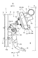
【図1】 車体の側面図である。
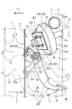
【図2】 車体の平面図である。
【図3】 自動車の衝突時の図1に相当する図である。
【図4】 自動車の衝突時の図2に相当する図である。
【符号の説明】
1 車体
2 車室
3 フロントパネル
4 フロントピラー
7 ピラーツーピラーチューブ
11 運転室
12 ドライバー
12a 膝
13 ブレーキ操作装置
16 ブラケット
16a 前端部
16b 側部
18 踏動部
19 枢支軸
20 ペダル
22 ブースター装置
24 ブラケット本体
25 一端部
26 他端部
27 連結板
28 係合バー
29 中途部
32 リンク
33 ブースター
34 マスタシリンダ
36 一部分
A 回動
B 回動
C 衝撃力
D 回動[0001]
[Technical field to which the invention belongs]
TECHNICAL FIELD The present invention relates to a secondary collision prevention apparatus for an automobile in which a brake booster device and a pedal disposed at a front end portion of a passenger compartment are prevented from causing a secondary collision with a driver at the time of a forward collision of the automobile. Is.
[0002]
[Prior art]
[0003]
[Patent Document 1]
Japanese Patent Laid-Open No. 10-71903 [0004]
The body of an automobile generally includes a front panel that forms the front surface of the vehicle compartment, and a pair of left and right front pillars that are disposed on the front side of the vehicle compartment behind the front panel. Conventional secondary collision prevention devices for automobiles include those disclosed in Patent Document 1 above. According to this, the bracket supported by the front panel, the brake booster device supported by the bracket so as to protrude rearward from the bracket, and the side of the booster device is supported by the front panel. And a connecting piece having one end connected to the rear portion of the booster device and the other end connected to the main bracket.
[0005]
When the booster device moves backward with respect to the front pillar at the time of a collision in front of the automobile, one end portion of the connecting piece that moves backward together with the booster device is almost the other end portion connected to the main bracket. As a result, the rear end of the booster device is deflected from the driver's knee, and the rear end of the booster device is prevented from colliding with the knee.
[0006]
[Problems to be solved by the invention]
By the way, in the above-mentioned conventional technology, the rear end of the booster device is deflected from the driver's knee at the time of a car collision to prevent a secondary collision, but at the time of the collision, the rear end of the booster device is at the center of the driver. Since it heads to the section, it is not always satisfactory in preventing a secondary collision with the driver, and there is still room for improvement.
[0007]
The present invention has been made by paying attention to the above situation, and in the event of a car collision, the rear end part or pedal of the booster device arranged at the front end part of the passenger compartment has a secondary collision with the driver. It is an object to be surely prevented.
[0008]
[Means for Solving the Problems]
The secondary collision prevention apparatus for an automobile of the present invention for solving the above problems is as follows. In addition, the code | symbol attached | subjected to each term in this term does not limit and interpret the technical scope of this invention to the content of the term of the following "embodiment of invention".
[0009]
The invention of claim 1 includes a
[0010]
The side 16b of the
[0011]
In addition to the invention of claim 1, the invention of
[0012]
In addition to the invention of claim 1, the invention of
[0013]
DETAILED DESCRIPTION OF THE INVENTION
Hereinafter, embodiments of the present invention will be described with reference to the drawings.
[0014]
1 and 2, reference numeral 1 denotes a vehicle body, and an arrow Fr indicates the front in the traveling direction of the vehicle. In addition, the right and left mentioned below shall mean the width direction of the vehicle body 1 toward the said front.
[0015]
The vehicle body 1 is made of sheet metal, and its interior space is a
[0016]
The
[0017]
Of the left and right side portions of the front portion of the
[0018]
The
[0019]
The one
[0020]
The
[0021]
As shown by the solid line in FIGS. 1 and 2, the lower portion of the
[0022]
According to the above configuration, the
[0023]
Here, in FIGS. 3 and 4, the strength and rigidity against the impact force C applied from the front of the
[0024]
In this case, as described above, since the side portion 16b of the
[0025]
In addition, since the above-described secondary collision is originally used by using the
[0026]
Further, in the above configuration, when the
[0027]
For this reason, the rearward movement of the
[0028]
In addition, since the above-described secondary collision is originally used with the pillar-to-pillar tube 7 having high strength and rigidity, the above-described secondary collision can be prevented with a simple configuration as long as a separate reinforcing material is not required. Achieved.
[0029]
Further, in the above configuration, when the
[0030]
3 and 4, the two-dot chain line corresponds to that in FIGS. 1 and 2, and the three-dot chain line in FIGS. 3 and 4 indicates that a part 36 of the
[0031]
And according to the said structure, it is prevented more reliably that the said
[0032]
Although the above is based on the illustrated example, the vehicle body 1 may be of a cab over type. Further, a part of the side part 16b of the
[0033]
【The invention's effect】
The effects of the present invention are as follows.
[0034]
The invention according to claim 1 is supported by the front panel that forms the front surface of the passenger compartment, a pair of left and right front pillars that are disposed on the front side of the passenger compartment behind the front panel, and the front panel. In an automobile having a bracket and a brake booster device supported by the bracket so as to protrude rearward from the bracket,
[0035]
When the side of the bracket is supported by the front pillar and the bracket moves backward relative to the front pillar in the event of a car collision, the bracket is substantially centered on the side of the bracket supported by the front pillar. As described above, while being accompanied by the booster device, it can be rotated outward toward the front pillar side .
[0036]
That is , when the vehicle collides forward, the strength and rigidity of the front panel against an impact force applied from the front of the vehicle are lower than that of the front pillar. For this reason, when the front panel is applied with the impact force at the time of a frontal collision of the automobile having the above configuration, the front panel moves backward with respect to the front pillar with the bracket and the booster device while being plastically deformed. To do.
[0037]
In this case, as described above, since the side portion of the bracket is supported by the front pillar, the bracket that moves rearward as described above has the booster substantially centered on the side portion supported by the front pillar. It is rotated outward toward the front pillar side with the device. Therefore, the rear end portion of the booster device is deflected to the outside of the driver, and the rear end portion of the booster device can be more reliably prevented from colliding with the driver.
[0038]
In addition, since the above-described secondary collision prevention originally uses a strong and rigid front pillar, the above-described secondary collision prevention can be achieved with a simple configuration as long as a separate reinforcing material is not required. .
[0039]
According to a second aspect of the present invention, there is provided a pillar-to-pillar tube installed on the left and right front pillars, and when the booster device moves rearward with respect to the front pillar at the time of a car collision, the booster device is connected to the pillar-to-pillar tube. The rearward movement is prevented by abutting against.
[0040]
For this reason, the rearward movement of the booster device beyond a certain degree is more reliably prevented by the pillar-to-pillar tube for reinforcing the vehicle body having high strength and rigidity. The next collision is more reliably prevented.
[0041]
In addition, since the above-mentioned secondary collision prevention originally uses a pillar-to-pillar tube with high strength and rigidity, the above-described secondary collision prevention can be achieved with a simple configuration as long as a separate reinforcing material is not required. Is done.
[0042]
The invention of
[0043]
For this reason, it is more reliably prevented that the pedal collides with the driver as much as the pedal side of the pedal rotates forward and away from the driver.
[Brief description of the drawings]
FIG. 1 is a side view of a vehicle body.
FIG. 2 is a plan view of a vehicle body.
FIG. 3 is a view corresponding to FIG. 1 at the time of automobile collision.
FIG. 4 is a view corresponding to FIG. 2 at the time of a car collision.
[Explanation of symbols]
DESCRIPTION OF SYMBOLS 1
Claims (3)
上記ブラケットの側部を上記フロントピラーに支持させ、自動車の衝突時に、上記フロントピラーに対し上記ブラケットが後方移動するとき、このブラケットが、上記フロントピラーに支持された上記ブラケットの側部をほぼ中心として、上記ブースター装置を伴いながら上記フロントピラー側に向かって外側方に回動させられるようにした自動車における2次衝突防止装置。A front panel that forms the front of the passenger compartment, a pair of left and right front pillars that are arranged on the front side of the passenger compartment behind the front panel, a bracket that is supported by the front panel, and a rear side of the bracket In a car equipped with a brake booster device supported by this bracket so as to protrude into
When the side of the bracket is supported by the front pillar and the bracket moves backward relative to the front pillar in the event of a car collision, the bracket is substantially centered on the side of the bracket supported by the front pillar. As a secondary collision prevention device for an automobile , the booster device can be rotated outward toward the front pillar side with the booster device.
Priority Applications (1)
| Application Number | Priority Date | Filing Date | Title |
|---|---|---|---|
| JP2003114170A JP4251908B2 (en) | 2003-04-18 | 2003-04-18 | Secondary collision prevention device for automobiles |
Applications Claiming Priority (1)
| Application Number | Priority Date | Filing Date | Title |
|---|---|---|---|
| JP2003114170A JP4251908B2 (en) | 2003-04-18 | 2003-04-18 | Secondary collision prevention device for automobiles |
Publications (2)
| Publication Number | Publication Date |
|---|---|
| JP2004314877A JP2004314877A (en) | 2004-11-11 |
| JP4251908B2 true JP4251908B2 (en) | 2009-04-08 |
Family
ID=33473845
Family Applications (1)
| Application Number | Title | Priority Date | Filing Date |
|---|---|---|---|
| JP2003114170A Expired - Fee Related JP4251908B2 (en) | 2003-04-18 | 2003-04-18 | Secondary collision prevention device for automobiles |
Country Status (1)
| Country | Link |
|---|---|
| JP (1) | JP4251908B2 (en) |
Families Citing this family (2)
| Publication number | Priority date | Publication date | Assignee | Title |
|---|---|---|---|---|
| JP5955704B2 (en) * | 2012-08-28 | 2016-07-20 | ダイハツ工業株式会社 | Front end structure of the vehicle |
| JP6298358B2 (en) * | 2014-05-27 | 2018-03-20 | ダイハツ工業株式会社 | Front end structure of the vehicle |
-
2003
- 2003-04-18 JP JP2003114170A patent/JP4251908B2/en not_active Expired - Fee Related
Also Published As
| Publication number | Publication date |
|---|---|
| JP2004314877A (en) | 2004-11-11 |
Similar Documents
| Publication | Publication Date | Title |
|---|---|---|
| US6810766B2 (en) | Brake pedal apparatus for vehicle | |
| EP1065114B1 (en) | Brake pedal apparatus for a vehicle | |
| JP2007320404A (en) | Automotive brake pedal equipment | |
| JPH115517A (en) | Automotive brake pedal device | |
| JP3804373B2 (en) | Automobile pedal support structure | |
| JP3838889B2 (en) | Pedal support structure for automobiles | |
| US7344158B2 (en) | Mounting structure of steering column for vehicles | |
| JP4029800B2 (en) | Automobile pedal support structure | |
| JP3804372B2 (en) | Automobile pedal support structure | |
| JP3848563B2 (en) | Vehicle front structure | |
| JP5983273B2 (en) | Pedal retraction control structure | |
| JP4251908B2 (en) | Secondary collision prevention device for automobiles | |
| JP3925845B2 (en) | Impact force mitigation device for secondary collision in automobiles | |
| JP3932702B2 (en) | Pedal bracket structure | |
| JPH08113148A (en) | Vehicle steering column support structure | |
| JP4338136B2 (en) | Preventing pedal retraction in automobiles | |
| JP3804424B2 (en) | Automobile pedal support device | |
| JP3892653B2 (en) | Automotive brake pedal equipment | |
| JP3804423B2 (en) | Automobile pedal support device | |
| JP4638317B2 (en) | Pedal device for vehicle | |
| JP3776225B2 (en) | Brake pedal structure of automobile | |
| JP3960521B2 (en) | Brake pedal displacement control device for automobile | |
| JP4761449B2 (en) | Preventing pedal retraction in automobiles | |
| JP3527420B2 (en) | Car front structure | |
| JP2003054390A (en) | Support structure for parking brake pedal |
Legal Events
| Date | Code | Title | Description |
|---|---|---|---|
| A621 | Written request for application examination |
Free format text: JAPANESE INTERMEDIATE CODE: A621 Effective date: 20051130 |
|
| A977 | Report on retrieval |
Free format text: JAPANESE INTERMEDIATE CODE: A971007 Effective date: 20081001 |
|
| A131 | Notification of reasons for refusal |
Free format text: JAPANESE INTERMEDIATE CODE: A131 Effective date: 20081008 |
|
| A521 | Request for written amendment filed |
Free format text: JAPANESE INTERMEDIATE CODE: A523 Effective date: 20081202 |
|
| TRDD | Decision of grant or rejection written | ||
| A01 | Written decision to grant a patent or to grant a registration (utility model) |
Free format text: JAPANESE INTERMEDIATE CODE: A01 Effective date: 20090120 |
|
| A01 | Written decision to grant a patent or to grant a registration (utility model) |
Free format text: JAPANESE INTERMEDIATE CODE: A01 |
|
| A61 | First payment of annual fees (during grant procedure) |
Free format text: JAPANESE INTERMEDIATE CODE: A61 Effective date: 20090120 |
|
| R150 | Certificate of patent or registration of utility model |
Ref document number: 4251908 Country of ref document: JP Free format text: JAPANESE INTERMEDIATE CODE: R150 |
|
| FPAY | Renewal fee payment (event date is renewal date of database) |
Free format text: PAYMENT UNTIL: 20120130 Year of fee payment: 3 |
|
| FPAY | Renewal fee payment (event date is renewal date of database) |
Free format text: PAYMENT UNTIL: 20140130 Year of fee payment: 5 |
|
| R250 | Receipt of annual fees |
Free format text: JAPANESE INTERMEDIATE CODE: R250 |
|
| R250 | Receipt of annual fees |
Free format text: JAPANESE INTERMEDIATE CODE: R250 |
|
| R250 | Receipt of annual fees |
Free format text: JAPANESE INTERMEDIATE CODE: R250 |
|
| R250 | Receipt of annual fees |
Free format text: JAPANESE INTERMEDIATE CODE: R250 |
|
| R250 | Receipt of annual fees |
Free format text: JAPANESE INTERMEDIATE CODE: R250 |
|
| R250 | Receipt of annual fees |
Free format text: JAPANESE INTERMEDIATE CODE: R250 |
|
| R250 | Receipt of annual fees |
Free format text: JAPANESE INTERMEDIATE CODE: R250 |
|
| LAPS | Cancellation because of no payment of annual fees |