JP4249950B2 - Paper tube cutting device and paper tube cutting method - Google Patents
Paper tube cutting device and paper tube cutting method Download PDFInfo
- Publication number
- JP4249950B2 JP4249950B2 JP2002189833A JP2002189833A JP4249950B2 JP 4249950 B2 JP4249950 B2 JP 4249950B2 JP 2002189833 A JP2002189833 A JP 2002189833A JP 2002189833 A JP2002189833 A JP 2002189833A JP 4249950 B2 JP4249950 B2 JP 4249950B2
- Authority
- JP
- Japan
- Prior art keywords
- cutting
- paper tube
- core
- cutting blade
- blade
- Prior art date
- Legal status (The legal status is an assumption and is not a legal conclusion. Google has not performed a legal analysis and makes no representation as to the accuracy of the status listed.)
- Expired - Fee Related
Links
Images


Classifications
-
- B—PERFORMING OPERATIONS; TRANSPORTING
- B26—HAND CUTTING TOOLS; CUTTING; SEVERING
- B26D—CUTTING; DETAILS COMMON TO MACHINES FOR PERFORATING, PUNCHING, CUTTING-OUT, STAMPING-OUT OR SEVERING
- B26D3/00—Cutting work characterised by the nature of the cut made; Apparatus therefor
- B26D3/16—Cutting rods or tubes transversely
-
- B—PERFORMING OPERATIONS; TRANSPORTING
- B24—GRINDING; POLISHING
- B24B—MACHINES, DEVICES, OR PROCESSES FOR GRINDING OR POLISHING; DRESSING OR CONDITIONING OF ABRADING SURFACES; FEEDING OF GRINDING, POLISHING, OR LAPPING AGENTS
- B24B9/00—Machines or devices designed for grinding edges or bevels on work or for removing burrs; Accessories therefor
- B24B9/007—Machines or devices designed for grinding edges or bevels on work or for removing burrs; Accessories therefor for end faces of tubes
-
- B—PERFORMING OPERATIONS; TRANSPORTING
- B26—HAND CUTTING TOOLS; CUTTING; SEVERING
- B26D—CUTTING; DETAILS COMMON TO MACHINES FOR PERFORATING, PUNCHING, CUTTING-OUT, STAMPING-OUT OR SEVERING
- B26D3/00—Cutting work characterised by the nature of the cut made; Apparatus therefor
- B26D3/16—Cutting rods or tubes transversely
- B26D3/164—Cutting rods or tubes transversely characterised by means for supporting the tube from the inside
-
- B—PERFORMING OPERATIONS; TRANSPORTING
- B26—HAND CUTTING TOOLS; CUTTING; SEVERING
- B26D—CUTTING; DETAILS COMMON TO MACHINES FOR PERFORATING, PUNCHING, CUTTING-OUT, STAMPING-OUT OR SEVERING
- B26D5/00—Arrangements for operating and controlling machines or devices for cutting, cutting-out, stamping-out, punching, perforating, or severing by means other than cutting
- B26D5/20—Arrangements for operating and controlling machines or devices for cutting, cutting-out, stamping-out, punching, perforating, or severing by means other than cutting with interrelated action between the cutting member and work feed
- B26D5/22—Arrangements for operating and controlling machines or devices for cutting, cutting-out, stamping-out, punching, perforating, or severing by means other than cutting with interrelated action between the cutting member and work feed having the cutting member and work feed mechanically connected
-
- B—PERFORMING OPERATIONS; TRANSPORTING
- B26—HAND CUTTING TOOLS; CUTTING; SEVERING
- B26D—CUTTING; DETAILS COMMON TO MACHINES FOR PERFORATING, PUNCHING, CUTTING-OUT, STAMPING-OUT OR SEVERING
- B26D2210/00—Machines or methods used for cutting special materials
- B26D2210/11—Machines or methods used for cutting special materials for cutting web rolls
-
- Y—GENERAL TAGGING OF NEW TECHNOLOGICAL DEVELOPMENTS; GENERAL TAGGING OF CROSS-SECTIONAL TECHNOLOGIES SPANNING OVER SEVERAL SECTIONS OF THE IPC; TECHNICAL SUBJECTS COVERED BY FORMER USPC CROSS-REFERENCE ART COLLECTIONS [XRACs] AND DIGESTS
- Y10—TECHNICAL SUBJECTS COVERED BY FORMER USPC
- Y10T—TECHNICAL SUBJECTS COVERED BY FORMER US CLASSIFICATION
- Y10T82/00—Turning
- Y10T82/10—Process of turning
-
- Y—GENERAL TAGGING OF NEW TECHNOLOGICAL DEVELOPMENTS; GENERAL TAGGING OF CROSS-SECTIONAL TECHNOLOGIES SPANNING OVER SEVERAL SECTIONS OF THE IPC; TECHNICAL SUBJECTS COVERED BY FORMER USPC CROSS-REFERENCE ART COLLECTIONS [XRACs] AND DIGESTS
- Y10—TECHNICAL SUBJECTS COVERED BY FORMER USPC
- Y10T—TECHNICAL SUBJECTS COVERED BY FORMER US CLASSIFICATION
- Y10T82/00—Turning
- Y10T82/22—Portable lathe for pipe turning
Abstract
Description
【0001】
【発明の属する技術分野】
本発明は、長尺状の記録材料を層状に巻き取る巻芯として適用される円筒状の紙管を、前記記録材料の巻取り方向と直交する幅方向に合わせて所定長さに切断するための紙管切断装置及び紙管切断方法に関するものである。
【0002】
【従来の技術及び発明が解決しようとする課題】
従来、長尺状記録材料を、円筒状の巻芯に所定の巻径まで巻き取って製品単位としたロール紙として製品化し出荷している。
【0003】
巻芯には、シート状の紙を層状に巻回し、かつ層間に接着剤を付与することで、接着して形成した所定の肉厚の円筒状の紙管が適用されている。
【0004】
ここで、記録材料には、多種の幅寸法があり、この幅寸法に合わせて巻芯である紙管の軸線方向長さを決めるようにしている。
【0005】
このため、紙管切断装置を用いて、軸線方向長さが比較的長い紙管を形成し、これを記録材料の幅寸法に合わせて軸直角方向に切断している。
【0006】
この紙管切断装置では、紙管を所定位置に位置決めした状態で、紙管に、当該紙管の内周面に接する外周を持つ切芯が挿入されるようになっている。また、紙管の外周に対向して、回転しない切断刃が配置されている。
【0007】
ここで、紙管のみを高速で回転させ、切断刃を紙管の外周に接近させることで、紙管は外周から切断される。
【0008】
切断刃は切断が完了すると、元の位置に戻り、紙管の軸線方向へ所定ピッチ移動し、上記切断動作を繰り返すことで、紙管は所定の軸線方向長さに寸断された状態で切芯に保持されることになり、この状態で切芯を抜き取ることで、短尺の紙管を生成することができる。
【0009】
ところで、近年、紙管の端面(リング状の肉厚部分)にこの紙管を巻芯として巻き取る記録材料に関する情報を付与することがなされている。この情報は,例えばバーコード等の所謂マシンリーダブルな情報として記録されるため、当該ロール紙を用いた画像記録処理装置での自動処理化に有利となる。
【0010】
しかしながら、紙管の端面は、前記切断工程中に切断刃が擦れる部分であり、この擦れによって熱が発生し(所謂アイロン効果)、紙管を形成するために用いられる接着剤が端面に溶け出して固化たり、紙管自体が加熱の作用によって表面が光沢をもつ滑らかな表面に化学変化を起こす場合がある。
【0011】
この接着剤の固化、並びに紙管自体の加熱による化学変化により、情報を印字するためのインクの浸透性が低下し、所謂インクののりが悪くなり、確実に情報を印字することができないという問題点が生じる。
【0012】
本発明は上記事実を考慮し、紙管の切断を行っても、当該紙管の切断面に印字するためのインクの浸透性を維持することができ、確実な印字を行うことができる紙管切断装置及び方法を得ることが目的である。
【0013】
【課題を解決するための手段】
請求項1に記載の発明は、長尺状の記録材料を層状に巻き取る巻芯として適用される円筒状の紙管を、前記記録材料の巻取り方向と直交する幅方向に合わせて所定長さに切断するための紙管切断装置であって、外周面が前記紙管の内周面と接するように挿入可能な切芯と、前記切芯を回転させる切芯回転手段と、前記紙管の外周に対向配置され、外周端が刃部とされた円板状の切断刃と、前記切芯に形成され、当該切芯の軸線方向における前記切断刃での切断位置に対応して設けられたリング状の溝部と、前記切芯に支持された状態で前記紙管を回転させる紙管回転手段と、前記切断刃を回転させる切断刃回転手段と、前記切芯回転手段、前記紙管回転手段、及び前記切断刃回転手段によるそれぞれの回転線速度が同一となるように制御する線速度制御手段と、を有することを特徴としている。
【0014】
請求項1記載の発明によれば、紙管回転手段及び切断刃回転手段によるそれぞれの回転線速度が同一となるように制御されることで、切断刃と紙管との相対回転がほとんどなくなり、切断刃は、実質的に紙管に押し込まれるように切断していくことになる。これにより、切断刃の側面で紙管の切断面を擦ることがなく、摩擦熱の発生を軽減することができる。摩擦熱の軽減により、薄肉の紙材を重ねて接着剤で張り合わせながら形成した紙管の各紙材の間から接着剤が溶け出して、切断面で固化してコーティングされるようなことがなくなり、後工程でのインクの付与時にインクを確実に浸透させ保持することができる。さらに、紙管と切断刃との回転線速度を同一とするのに加え、切芯の回転線速度も同一とし、切断刃と紙管は相反する方向に回転し、紙管と切芯は同一方向に回転することで、切断刃と切芯との相対回転も軽減され、切断刃が紙管に食い込んでいくとき、摩擦熱が発生しにくくなる。
【0015】
請求項2に記載の発明は、前記紙管回転手段及び切芯回転手段が同一の駆動源で回転されることを特徴としている。
【0016】
請求項2に記載の発明によれば、切芯と紙管とは同軸であるため、同一の駆動源で回転させることが容易であり、駆動源の簡略化を図ることができる。
【0017】
請求項3に記載の発明は、前記切断刃による紙管の両切断面にそれぞれ対向配置され、互いに相反する方向に回転することで、内周端に残るバリを切削して取り除くテーパ状の切削面を備えた一対の回転部材をさらに有することを特徴としている。
【0018】
請求項3に記載の発明によれば、切断刃と紙管との相対回転差を軽減することで、切断時のバリをほぼ取り除くことができ、切芯を紙管から抜き取る作業を円滑とすることができる。しかし、バリは若干量残っているため、製品の品質管理としてバリ取りを行っている。このとき、テーパ状の切削面を両端面に突き当て、互いに相反する方向に回転することで、紙管を保持する必要がなく、確実にバリ取りを行うことができる。
【0019】
請求項4に記載の発明は、長尺状の記録材料を層状に巻き取る巻芯として適用される円筒状の紙管を、前記記録材料の巻取り方向と直交する幅方向に合わせて所定長さに切断するための紙管切断方法であって、前記紙管の内周面と接触する外周を持つ切芯を回転可能に挿入した状態で、円板状の切断刃を回転させて、当該紙管の軸線方向の所定の位置で切断する際に、前記切断刃と前記紙管は相反する方向に回転させ、前記紙管と前記切芯は同一方向に回転させると共に、前記切芯の回転線速度、及び前記切断刃の回転線速度に対して同一の回転線速度となるように、紙管を回転させながら切断することを特徴としている。
【0020】
請求項4に記載の発明によれば、通常は切断刃を高速に回転し、紙管を略1回転低速で回転すれば紙管の切断は可能であるが、切断面に生じる摩擦熱を軽減するために、切断刃と紙管は相反する方向に回転させ、紙管と切芯は同一方向に回転させると共に、切芯の回転線速度、及び切断刃の回転線速度に対して同一の回転線速度となるように、紙管を回転させながら切断する。これにより、切断面に接着剤等が溶け出して、コーティングされることが防止され、後工程でのインクののりが向上する。
【0021】
請求項5に記載の発明は、前記切芯には、前記切断刃と対応する部分にリング状の溝が形成され、前記切断刃の紙管切断時の刃先と前記切芯との干渉を回避することを特徴としている。
【0022】
請求項5に記載の発明によれば、紙管の内周面と切芯の外周面とは接触状態にあるため、切断刃で紙管を切断する際に、刃先が切芯に当接し、刃こぼれを起こすことがある。そこで、切芯に切断位置に対応してリング状の溝を形成しておくことで、切断刃の逃げ溝とすることができる。
【0025】
【発明の実施の形態】
以下に、本発明の紙管切断装置の実施の形態を説明するが、この紙管切断装置は、以下で説明するロール紙の製造工程の中の紙管切断工程に適用されるものである。
【0026】
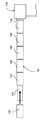
(ロール紙製造工程の概略)
図1には、本実施の形態に係るロール紙の製造工程図が示されている。
【0027】
原材料としての長尺紙管10が準備され、この長尺紙管10は、まず、紙管切断工程において、所定のピッチで分断される。この紙管切断工程では、長尺紙管10に切芯12が緊密に挿入され、その後、切断刃14が長尺紙管10の軸線方向に前記所定のピッチで移動され、各位置で切断を行なう。なお、長尺紙管10の両端は端材10Bとして廃棄され、中間部の複数の短尺の紙管10Aが巻芯として適用される。
【0028】
紙管切断工程を終えた紙管10Aは、それぞれ内周側端面にバリが発生しているため、紙管バリ取り工程において、このバリを取り除く。
【0029】
すなわち、図2に示される如く、紙管10Aの両端にテーパ状の切削面を持った一対の回転体16をそれぞれ紙管10Aと同軸に配置し、互いに相反する方向に回転させることで、バリを削りとっている。なお、このテーパー状の切削面には、バリを削り取る切削刃が埋め込まれている。
【0030】
バリが取り除かれた紙管10Aは、情報書込み工程へ送られ、紙管10Aの端面(肉厚部分)に情報が印字される。なお、この情報は、次工程で紙管10Aに巻き取られる記録材料の種類、サイズ等をマシンリーダブルなバーコード18で印字するようになっている。図1では、バーコード18が紙管10Aの下地色の状態で印字するように図示したが、実際には、赤外線非吸収インクを下地色として塗布し、その上に赤外線吸収インクをバーコード18として印字するようにして、濃淡の差を無くすようにしている。
【0031】
情報書込工程において、バーコード18が印字されると、紙管10Aを巻芯として記録材料20が層状に巻き取られ、次いで包装工程において所定長さ分の記録材料20が巻き取られた状態で遮光性の包装紙22で包装する。なお、包装後は、内部をほぼ真空状態としている。
【0032】
包装されたロール状の記録材料20は、梱包工程において、ダンボール24に梱包され製品として出荷されるようになっている。
【0033】
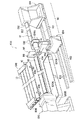
(紙管切断装置の構成)
図3乃至図5には、本実施の形態に係る紙管切断装置100が示されている。紙管切断装置100のメインステージ102上には、略V字形に形成され、当該V字形状の2点で長尺紙管10を支持する支持台104が配設されている。
【0034】
この支持台104では、V字型の角度が一定であるため、長尺紙管10を支持する際に、長尺紙管10の軸直角方向の位置を常に同一の位置で支持することができるようになっている。
【0035】
メインステージ102の奥側には、複数の長尺紙管10をストックするストック部106が設けられている。ストック部106と前記メインステージ102の支持台104との間には、長尺紙管10が転動するスロープ108が形成されており、長尺紙管10は、このスロープ108を介してストック部106から支持台104へと送られるようになっている。
【0036】
なお、スロープ108のストック部106側端部には、ストッパ機構109が設けられ、このストッパ機構109の開閉動作により、長尺紙管10は1本ずつ支持台104へ送り込まれるようになっている。
【0037】
前記メインステージ102には、待機ステージ110が併設されている。この待機ステージ110には、レール部112が設けられ、移動体114が支持されている。移動体114は、レール部112に案内されて待機ステージ110内をメインステージに対して接近、離間するように移動可能となっている。
【0038】
移動体114には、円筒状の切芯12が取り付けられている。切芯12は、その一端部(前記メインステージ102に遠い側の端部)において、前記移動体114に片持ち状態で支持されている。
【0039】
この切芯12の軸線は、前記メインステージ102の支持台104に支持された長尺紙管10の軸線と一致するように配設されている。
【0040】
切芯12は、前記長尺紙管10の内径と所定の寸法公差でほぼ同一の外径とされている。すなわち、移動体114が待機ステージ110において、メインステージ102から最も離れた状態で待機しており、長尺紙管10がストック部106から送り込まれ、支持台104に支持された状態で、移動体114をメインステージ102方向へレール部112を介して移動させると、切芯12は、長尺紙管10に挿入されながら軸線方向移動することになる。この移動により、切芯12は、長尺紙管10に挿入される。
【0041】
なお、メインステージ102と待機ステージ110との間には、円孔116が設けられた隔壁118が立設配置されており、前記切芯12は、この円孔116を貫通して移動するようになっている。この状態で、長尺紙管10は支持台104から切芯12に受け渡された形となる。
【0042】
メインステージ102における前記待機ステージ110とは反対側には、駆動チャック部120が配設されている。この駆動チャック部120は、前記待機ステージ110から接近してくる切芯12の移動方向先端部並びに長尺紙管10の端部を保持する保持部120Aを備えている。
【0043】
また、この駆動チャック部120の保持部120Aは、前記保持した切芯12及び紙管10Aを軸回転させるように回転可能とされ、駆動部120Bの駆動力で当該切芯及び長尺紙管10を所定の回転速度で回転させることができるようになっている。
【0044】
メインステージ102には、前記待機ステージ110側から駆動チャック部120にかけて、レール部122が配設されており、切断ユニット124が支持されている。この切断ユニット124は、レール部122に案内されて、待機ステージ110側から駆動チャック部120側までの間を移動可能となっている。
【0045】
切断ユニット124には、円板上の切断刃14が設けられている。切断刃14は、その周端全域が刃部14Aとして先鋭に研ぎ澄まされている。
【0046】
切断刃14は、その回転軸線が前記切芯12及び長尺紙管10の軸線と平行とされ、駆動部124Aの駆動力によって所定の回転速度で回転するようになっている。
【0047】
この切断ユニット124には、前記切断刃14を前記切芯12に支持された長尺紙管10に対して半径方向から接近、離間させる接離機構部124Bが設けられている。これにより、切断刃14を回転させた状態で、長尺紙管10へ接近させることで、長尺紙管10を外周から切断していくことができる。
【0048】
なお、図5に示される如く、この切断刃14の接近により切断時には、長尺紙管10の位置を保持するための押さえローラ部(一対のローラ126A、126Bで構成)126が切断刃14とは反対側から長尺紙管10を押さえるようになっている。
【0049】
図6に示される如く、切断刃14は、軸芯から所定の半径寸法までの肉厚寸法t1が、刃部14Aが形成される周端の肉厚寸法t2(刃部14Aの基部)よりも極端に厚く形成されている。すなわち、切断刃14を回転駆動する際に、肉厚方向の回転のぶれがあると、長尺紙管10を切断する際の切断代が大きくなるため、このぶれを防止し、回転を安定させるためのカウンタ(錘)機能を持たせている。また、周端は、長尺紙管10の切断時に長尺紙管10に入り込む分(肉厚寸法t2から徐々に鋭利となっている部分)のみ薄肉として切断代を小さくしている。
【0050】
ここで、前記切断刃14を所定の回転速度で回転させながら、長尺紙管10へ接近させる際、当該長尺紙管10並びに切芯12も所定の回転速度で回転させている。
【0051】
このとき、図7に示される如く、切断刃14の回転線速度vsと、長尺紙管10の回転線速度vpとがほぼ同一(所定の速度差の範囲内)となるようにそれぞれの回転速度が制御されている。また、回転方向は、互いに相反する方向とされ、一方の回転が他方の回転を妨げるようなことがなく、例えば、一対のローラが互いに接触して回転するようなイメージで回転するようになっている。なお、本実施の形態では、切芯12も、前記長尺紙管10の回転速度vpで回転させている。
【0052】
このため、切断刃14と長尺紙管10との相対速度差がほとんどなく、刃部14Aが長尺紙管10に食い込んでいくとき、摩擦熱が発生しにくい構造となっている。
【0053】
切断ユニット124は、予め定められた所定のピッチで前記レール部122を移動し、それぞれの位置で前記切断刃14の長尺紙管10への接近、離間を実行している。
【0054】
この所定のピッチ駆動は、ACサーボモータにより高精度に位置決めされるようになっている。
【0055】
また、この所定のピッチ寸法に合わせて、図6に示される如く、前記切芯12には、予め所定幅の溝部128が形成されている。この溝部128の幅寸法は、0.1mm〜1.0mmであり、好ましくは0.2mm〜0.6mmとなっている。なお、実際の製作上の目安としては、0.3mm〜0.5mmを目標値として形成している。
【0056】
この溝部128は、一体ものの切芯12に対して、所定の深さの溝部128を切り出して形成してもよいが、本実施の形態では、図8に示される如く、切芯12を本体パイプ部130と、当該本体パイプ部130に複数の切芯ピース132を連鎖状に挿嵌して構成している。
【0057】
切芯ピース132の端面は、すり鉢上に凹陥されており、その軸芯から所定の半径の円形の突起部132Aが形成されている。この突起部132Aの先端面は、切芯ピース132の外周端よりも若干突出されており(ここでは、突出寸法Tが約0.2mm)、連鎖状に本体パイプ部130に挿嵌していくとき、突起部132Aの先端面同士が突き当てられるため、前記突出量の2倍の寸法分だけ切芯ピース132の外周端に隙間が生じ、この隙間が前記溝部128となり得る。このような、切芯ピース132を連鎖的に本体パイプ部130に挿入して切芯12を構成することで、溝部128の位置の変更時には切芯ピース132を差し換えるのみでよく、組み付けの作業性を向上することができる。
【0058】
前記切断ユニット124が所定ピッチで移動し、接離機構部124Bの駆動によって、切断刃14を長尺紙管10へ接近させることで、長尺紙管10は所定の軸線方向寸法の、複数の短尺の紙管10Aとなる。
【0059】
また、切断が完了すると、待機ステージ110の移動体114をメインステージ102から離間する方向へレール部112を介して移動するようになっている。このとき、メインステージ102と待機ステージ110との間に設けられた隔壁118において、切芯12は、円孔116内を通過するが、前記紙管10Aは、その端面が円孔116の周縁に当接し、その移動が阻止される。これにより、切芯12は、紙管10Aを支持台104に残して、待機ステージ110へ退避されることになる。なお、図示は省略したが、隔壁118には、切芯12がこの隔壁118の円孔116を通過する際、切芯12の溝部128に向けてエアーを吹き付け、切りカスを取り除くブロワ気候部が設けられている。
【0060】
支持台104に残った紙管10A(複数の短尺の紙管10A)は、支持台104が傾斜することで、次工程である紙管バリ取り工程へと送り出されるようになっている。
【0061】
以下に本実施の形態の作用を説明する。
【0062】
原材料としての長尺紙管10は、ストック部106にストックされた状態で、ストッパ機構を解除すると、最先の長尺紙管10がスロープ108を転動し、支持台104へ送り込まれる。支持台104は、略V字形とされているため、円筒形の長尺紙管10は、軸直角断面で見ると2点に支持されることになり、支持台104に対する相対位置が一義的に決まり、所定の位置への位置決めがなされる。
【0063】
支持台104に長尺紙管10の位置決めがなされると、待機ステージ110に待機している移動体114がレール部112に案内されてメインステージ102方向へ移動を開始する。これにより、この移動体114に片持ち状態で支持されている切芯12がメインステージ102方向へ軸線移動される。この切芯12の軸線と、前記支持台104に支持された長尺紙管10の軸線とは一致しており、移動体114の移動につれて、切芯12は、長尺紙管10に挿入されていく。
【0064】
切芯12の外径は、長尺紙管10の内径に対して所定の寸法公差で緊密に挿入されていくため、挿入後は切芯12の外周と、長尺紙管10の内周とはほぼ接触した状態となる。
【0065】
切芯12が長尺紙管10に完全に挿入されると、この切芯12の軸線移動方向先端と、これに対応する長尺紙管10の端面とが、駆動チャック部120の保持部120Aに保持される。この保持部120Aによる保持後は、押さえローラ部126が長尺紙管10に接近し、一対のローラ126A、126Bによって長尺紙管10と接触する。
【0066】
駆動チャック部120では、保持部120Aが駆動部120Bの駆動力で回転する。この回転によって、切芯12及び長尺紙管10が所定の回転速度で回転する。
【0067】
この状態では、切断ユニット124がレール部122に案内されて、初期位置へ移動し位置決めがなされる。位置決め後、切断刃14が駆動部124Aの駆動力で所定の回転速度で回転を開始する。
【0068】
切断刃14は、接離機構部124Bによって、長尺紙管10へ接近され、長尺紙管10を外周から切断していく。
【0069】
このとき、長尺紙管10は、押さえローラ部126によって切断刃14とは反対側から長尺紙管10を押さえているため、長尺紙管10が軸ずれを起こすことはない。
【0070】
切断刃14による切断時は、刃部14Aが長尺紙管10に食い込んでいくが、このとき、切断刃14の軸芯から所定の半径寸法までの肉厚寸法t1が、刃部14Aが形成される周端の肉厚寸法t2よりも極端に厚く形成されている。これにより、周端の刃部14Aが食い込む量が制限され、基本的には、刃部14Aは、長尺紙管10が完全に(刃部14Aが内周面まで到達するまで)切断されるまでの移動量に制限することができる。
【0071】
また、上記肉厚を大きくとることで、回転を安定させるためのカウンタ(錘)機能を持たせ、切断刃14を回転駆動する際に、肉厚方向の回転のぶれを抑制し、長尺紙管10を切断する際の切断代を小さくすることができる。
【0072】
ここで、前記切断刃14を所定の回転速度で回転させながら、長尺紙管10へ接近させる際、当該長尺紙管10並びに切芯12も所定の回転速度で回転させている。それぞれの回転は、切断刃14が回転線速度vs、長尺紙管10が回転線速度vpとされ、これらはほぼ同一(所定の速度差の範囲内)である。また、回転方向は、互いに相反する方向であるため、切断刃14と長尺紙管10との相対速度差がほとんどなく、刃部14Aが長尺紙管10に食い込んでいくとき、摩擦熱が発生しにくい。
【0073】
摩擦熱が発生しないということは、薄肉シートを接着剤を巻き付けて形成した長尺紙管10の端面から接着剤が溶け出し、固化するようなことがなく、所謂アイロン効果による端面の光沢化を制限することができる。なお、光沢化は前記接着剤のみに起因するのではなく、長尺紙管10の材質の化学変化によっても起こり得るが、摩擦熱の軽減は、この化学変化の防止にもつながる。
【0074】
なお、この端面の光沢化は、情報書込み工程におけるインクののりを悪くする原因となっていたが、上記のように、切断刃14と長尺紙管10とをほぼ同一の回転線速度で相反する方向に回転させることで、この不具合を解消することができる。
【0075】
また、切断刃14は、長尺紙管10の内周面まで完全に切断させるためには、刃部14Aが長尺紙管10の内周面よりも内側まで至らなくてはならない。このため、刃部14Aと切芯12とが干渉することになるが、本実施の形態では、予め所定幅の溝部128を形成し、刃部14Aとの干渉を回避している。この溝部128の幅寸法は、実際の製作上は、0.3mm〜0.5mmを目標値として形成している(許容範囲は、0.1mm〜1.0mm)。
【0076】
このように溝部128の幅寸法を制限することで、切断時のバリの量を軽減することができ、後述する切断後の切芯12の抜き取り作業時の抵抗力をほとんどなくすことができる。
【0077】
初期位置での切断刃14による切断が終了すると、接離機構部124Bは、切断刃14を元の位置に戻し、駆動部124Aの駆動力で切断ユニット124を次の切断位置まで移動させ位置決めする。その後、接離機構部124Bの駆動力で切断刃14を長尺紙管10へ接近、離間し切断を実行する。
【0078】
以上の工程を所定回数繰り返すことで、長尺紙管10から、複数の短尺の紙管10Aを得ることができる。なお、長尺紙管10の軸線方向両端部には、短尺の紙管10Aの寸法によって、余り部分ができることもある。例えば、長尺紙管10の長さ寸法が1600mmで、必要な短尺の紙管10Aの幅寸法(軸線方向寸法)が152mmの場合、1600/152=10個余り80mmとなり、両端部にそれぞれ40mmの端材が発生する。なお、短尺の紙管10Aの現状での寸法は、89mm〜152mmであり、この寸法に合わせて、切芯12を構成する切芯ピース132を選択し、本体パイプ部130に連鎖的に挿入していけばよい。また、切断刃14の移動ピッチも上記サイズに合わせて設定すればよい。
【0079】
全ての切断処理が終了した状態では、複数の紙管10Aは、依然切芯12に保持されたままで同軸状態で保持されており、この状態で、待機ステージ110の移動体114をメインステージ102から離れる方向へレール部112に案内して移動する。これにより、切芯12は、徐々にメインステージ102から待機ステージ110へと軸線移動を開始する。
【0080】
ここで、メインステージ102と待機ステージ110との間には、隔壁118が設けられ、切芯12はこの隔壁118に設けられた円孔116を通過するが、紙管10Aは、当該円孔116の周端と干渉して、その移動が阻まれる。これにより、切芯12を複数の紙管10Aから抜き取ることができる。
【0081】
抜き取られた複数の紙管10Aはそれぞれ支持台104に支持され、この支持台104が傾斜することで、次工程である紙管バリ取り工程へ送り出される。
【0082】
上記のように、紙管切断工程を終えた紙管10Aは、それぞれ内周側端面にバリが発生しているため、紙管バリ取り工程において、このバリを取り除く。すなわち、紙管10Aの両端にテーパ状の切削面を持った一対の回転体16をそれぞれ紙管10Aと同軸に配置し、互いに相反する方向に回転させることで、バリを削りとっている。なお、このバリは、従来は、切芯に形成した切断刃の逃げ溝を必要以上に大きくとっていたため、大きなバリが発生していたが、本実施の形態では、切芯12に設けた溝部128の幅寸法を規定したため、わずかなバリであり、バリ取り工程の負荷を緩和することができる。
【0083】
バリが取り除かれた紙管10Aは、情報書込み工程へ送られ、紙管10Aの端面(肉厚部分)に情報が印字される。
【0084】
本実施の形態にける情報の印字は、図9に示される如く、短尺の紙管10Aを円状移動軌跡の下部接線方向から装填し、当該装填位置を含む8ステップで回転移動する間に処理が実行される。
【0085】
すなわち、装填部Aに紙管10Aが装填されると、次の停止位置で赤外線非吸収インクを端面全体に塗布する(下地形成部B)。次に、1ステップ移動して、赤外線ヒータによって下地を乾燥させる(下地乾燥部C)。次いで、次のステップでは、赤外線吸収インクを用いて情報を放射状に印字する(情報形成部D)。情報は、次工程で紙管10Aに巻き取られる記録材料の種類、サイズ等をマシンリーダブルなバーコード18で印字する。
【0086】
さらに、次のステップでは、赤外線ヒータによってバーコード18で印字した情報を乾燥させる(情報乾燥部E)。次のステップでは、形成した情報の読み取りチェックを実行し(読取チェック部F)、NGの場合にはこのステップで廃棄し、OKの場合は次のステップへ進む。次のステップでは紙管10Aの周面にロットNo.等を付与し(周面印字G)、最終ステップで排出して(排出部H)、次工程である記録材料巻取工程へ送り出す。すなわち、装填部Aから排出部Hまでほぼ360°回転している間に複数の印字処理を実行する。
【0087】
また、下地として適用した赤外線非吸収インクと、情報(バーコード18)を印字した赤外線吸収インクはそれぞれ濃度の高い色(ほぼ黒色に近い)であるため、目視では判別し難いが、所定の波長の光源の下では、情報を読み取ることができる。このような、インクによる印字の際、前述したように紙管10Aの端面に接着剤の固化等により光沢化されていないため、インクののりがよく、確実に情報を印字することができる。
【0088】
情報書込工程において、バーコード18が印字されると、紙管10Aを巻芯として記録材料20が層状に巻き取られ、次いで包装工程において所定長さ分の記録材料20が巻き取られた状態で遮光性の包装紙22で包装する。なお、包装後は、内部をほぼ真空状態としている。包装されたロール状の記録材料20は、梱包工程において、ダンボール24に梱包され製品として出荷される。
【0089】
以上説明したように、本実施の形態では、切断刃14の刃部14AAの回転線速度と、長尺紙管10の外周(実際には、肉厚方向の中央部)の回転線速度をほぼ同一とし(所定の速度差の範囲内とし)、互いに相反する方向へ回転させながら切断を実行するようにした。これにより、刃部14AAは、理論的には、垂直に長尺紙管10に食い込むように切断することになり、刃部14Aと、長尺紙管10との摺動による摩擦熱の発生が軽減される。この摩擦熱の軽減により、切断された短尺の紙管10Aの端面に接着剤た溶け出して固化したり、紙管10A自体が化学変化を起こして、端面が光沢化されるようなことがなくなり、この端面に情報を印字する際に使用するインクののりを向上することができる。
【0090】
【発明の効果】
以上説明した如く本発明では、紙管の切断を行っても、当該紙管の切断面に印字するためのインクの浸透性を維持することができ、確実な印字を行うことができるという優れた効果を有する。
【図面の簡単な説明】
【図1】本実施の形態に係るロール紙の製造工程の流れを示す概略図である。
【図2】本実施の形態に係る紙管バリ取り工程の拡大図である。
【図3】本実施の形態に係る紙管切断装置の全体の概略を示す斜視図である。
【図4】本実施の形態に係る紙管切断装置のメインステージの正面図である。
【図5】図3における切断動作中の紙管切断装置を示す斜視図である。
【図6】切断刃が紙管を切断しているときの紙管の軸直角断面図である。
【図7】切断刃が紙管を切断しているときの紙管の軸方向断面図である。
【図8】切芯の構造を示す正面図である。
【図9】情報書込み工程の詳細を示す概略図である。
【符号の説明】
10 長尺紙管
10A 紙管
10B 端材
12 切芯
14 切断刃
14A 刃部
16 回転体(回転部材)
18 バーコード
20 記録材料
22 包装紙
24 ダンボール
100 紙管切断装置
102 メインステージ
104 支持台
106 ストック部
108 スロープ
110 待機ステージ
112 レール部
114 移動体
116 円孔
118 隔壁
120 駆動チャック部
120A 保持部
120B 駆動部(紙管回転手段、切芯回転手段)
122 レール部
124 切断ユニット
124A 駆動部(切断刃回転手段)
124B 接離機構部
126 押さえローラ部
128 溝部
130 本体パイプ部
132 切芯ピース
132 突起部[0001]
BACKGROUND OF THE INVENTION
The present invention is to cut a cylindrical paper tube applied as a winding core for winding a long recording material in layers into a predetermined length in accordance with a width direction orthogonal to the winding direction of the recording material. The present invention relates to a paper tube cutting apparatus and a paper tube cutting method.
[0002]
[Prior art and problems to be solved by the invention]
2. Description of the Related Art Conventionally, long recording materials have been commercialized and shipped as roll paper that is wound up to a predetermined winding diameter on a cylindrical core to make a product unit.
[0003]
A cylindrical paper tube having a predetermined thickness formed by bonding a sheet-like paper in layers and applying an adhesive between the layers is applied to the core.
[0004]
Here, the recording material has various width dimensions, and the length in the axial direction of the paper tube which is the core is determined in accordance with the width dimensions.
[0005]
For this reason, a paper tube cutting device is used to form a paper tube having a relatively long axial length, and this is cut in the direction perpendicular to the axis in accordance with the width dimension of the recording material.
[0006]
In this paper tube cutting device, a cutting core having an outer periphery contacting the inner peripheral surface of the paper tube is inserted into the paper tube with the paper tube positioned at a predetermined position. Further, a non-rotating cutting blade is disposed opposite the outer periphery of the paper tube.
[0007]
Here, the paper tube is cut from the outer periphery by rotating only the paper tube at a high speed and bringing the cutting blade closer to the outer periphery of the paper tube.
[0008]
When cutting is completed, the cutting blade returns to its original position, moves by a predetermined pitch in the axial direction of the paper tube, and repeats the above cutting operation, so that the paper tube is cut into the predetermined axial length and the core is cut. In this state, a short paper tube can be generated by removing the cutting core.
[0009]
By the way, in recent years, information relating to a recording material for winding the paper tube as a winding core has been given to the end surface (ring-shaped thick portion) of the paper tube. This information is recorded as so-called machine-readable information such as a barcode, which is advantageous for automatic processing in an image recording processing apparatus using the roll paper.
[0010]
However, the end surface of the paper tube is a portion where the cutting blade is rubbed during the cutting process, and heat is generated by this rubbing (so-called iron effect), and the adhesive used to form the paper tube melts into the end surface. In some cases, the paper tube itself solidifies, or the paper tube itself undergoes a chemical change to a smooth surface having a glossy surface due to the action of heating.
[0011]
Due to the solidification of the adhesive and the chemical change caused by heating of the paper tube itself, the permeability of the ink for printing information is lowered, so-called ink paste is deteriorated, and information cannot be printed reliably. A point is created.
[0012]
In consideration of the above facts, the present invention can maintain the permeability of the ink for printing on the cut surface of the paper tube even when the paper tube is cut, and can perform reliable printing. It is an object to obtain a cutting device and method.
[0013]
[Means for Solving the Problems]
According to the first aspect of the present invention, a cylindrical paper tube that is applied as a winding core for winding a long recording material in layers is aligned with a width direction perpendicular to the winding direction of the recording material to a predetermined length. A paper tube cutting device for cutting the paper tube, and a core that can be inserted so that the outer peripheral surface is in contact with the inner peripheral surface of the paper tube;Cutting center rotating means for rotating the cutting core;A disk-shaped cutting blade disposed opposite to the outer periphery of the paper tube and having an outer peripheral edge as a blade portion, and formed on the cutting core, corresponding to a cutting position on the cutting blade in the axial direction of the cutting core. A ring-shaped groove portion provided on the cutting core, a paper tube rotating means for rotating the paper tube while being supported by the cutting core, and a cutting blade rotating means for rotating the cutting blade., The core rotation means,The paper tube rotating meansAnd saidEach rotation linear velocity by cutting blade rotating meansAre the sameControl to beLinear velocity control meansWhen,HaveIt is characterized by that.
[0014]
According to the first aspect of the present invention, the respective linear rotation speeds of the paper tube rotating means and the cutting blade rotating means.Are the sameAs a result, the relative rotation between the cutting blade and the paper tube is almost eliminated, and the cutting blade is cut so as to be substantially pushed into the paper tube. Thereby, it is possible to reduce the generation of frictional heat without rubbing the cutting surface of the paper tube with the side surface of the cutting blade. By reducing the frictional heat, the adhesive melts from the paper material of the paper tube that is formed while laminating thin paper materials and pasting them together with an adhesive, so that it is not solidified and coated on the cut surface. When ink is applied in a subsequent process, the ink can be reliably infiltrated and held.Furthermore, in addition to making the rotation linear velocity of the paper tube and the cutting blade the same, the rotation linear velocity of the cutting core is also the same, the cutting blade and the paper tube rotate in opposite directions, and the paper tube and the cutting core are the same. By rotating in the direction, the relative rotation between the cutting blade and the cutting core is also reduced, and when the cutting blade bites into the paper tube, frictional heat is hardly generated.
[0015]
The invention described in claim 2The paper tube rotating means and the core rotating means are rotated by the same drive source.It is characterized by that.
[0016]
According to invention of Claim 2,Since the cutting core and the paper tube are coaxial, it is easy to rotate with the same drive source, and the drive source can be simplified.
[0017]
The invention according to claim 3A pair of rotating members each having a tapered cutting surface that is disposed opposite to both cutting surfaces of the paper tube by the cutting blade and rotates in opposite directions to remove burrs remaining on the inner peripheral edge by cutting. Have moreIt is characterized by that.
[0018]
According to invention of Claim 3,By reducing the relative rotation difference between the cutting blade and the paper tube, burrs at the time of cutting can be almost removed, and the operation of removing the cutting core from the paper tube can be made smooth. However, since some burrs remain, deburring is performed for product quality control. At this time, it is not necessary to hold the paper tube by abutting the tapered cutting surfaces against the both end surfaces and rotating in opposite directions, so that deburring can be reliably performed.
[0019]
The invention according to claim 4Cutting of a paper tube for cutting a cylindrical paper tube applied as a core for winding a long recording material into a layer to a predetermined length in the width direction perpendicular to the winding direction of the recording material A method of rotating a disk-shaped cutting blade in a state where a cutting core having an outer periphery that contacts an inner peripheral surface of the paper tube is rotatably inserted, and a predetermined position in an axial direction of the paper tube When cutting, the cutting blade and the paper tube are rotated in opposite directions, the paper tube and the cutting core are rotated in the same direction, the linear rotation speed of the cutting core, and the rotation of the cutting blade Cutting while rotating the paper tube so that the linear velocity is the same as the linear velocityIt is characterized by that.
[0020]
According to invention of Claim 4,Normally, the paper tube can be cut by rotating the cutting blade at a high speed and rotating the paper tube at a low speed for about one rotation. However, in order to reduce the frictional heat generated on the cutting surface, the cutting blade and the paper tube are in conflict. The paper tube and core are rotated in the same direction, and the paper tube is rotated so that the rotational linear velocity of the core and the rotational linear velocity of the cutting blade are the same. Cut while letting. As a result, the adhesive or the like dissolves on the cut surface and is prevented from being coated, and the ink paste in the subsequent process is improved.
[0021]
The invention described in claim 5The cutting core is formed with a ring-shaped groove at a portion corresponding to the cutting blade to avoid interference between the cutting edge and the cutting core when cutting the paper tube of the cutting blade.It is characterized by that.
[0022]
According to the invention of claim 5,Since the inner peripheral surface of the paper tube and the outer peripheral surface of the cutting core are in contact with each other, when cutting the paper tube with a cutting blade, the cutting edge may come into contact with the cutting core and cause blade spillage. Therefore, by forming a ring-shaped groove on the cutting core corresponding to the cutting position, it can be used as a relief groove of the cutting blade.
[0025]
DETAILED DESCRIPTION OF THE INVENTION
Hereinafter, an embodiment of the paper tube cutting device of the present invention will be described. This paper tube cutting device is applied to a paper tube cutting process in a roll paper manufacturing process described below.
[0026]
(Outline of roll paper manufacturing process)
FIG. 1 shows a production process diagram of roll paper according to the present embodiment.
[0027]
A
[0028]
Since the
[0029]
That is, as shown in FIG. 2, a pair of
[0030]
The
[0031]
In the information writing process, when the
[0032]
The packaged roll-shaped
[0033]
(Configuration of paper tube cutting device)
3 to 5 show a paper
[0034]
Since the support table 104 has a constant V-shaped angle, when the
[0035]
On the back side of the
[0036]
A
[0037]
The
[0038]
A
[0039]
The axis of the
[0040]
The cutting
[0041]
A
[0042]
On the opposite side of the
[0043]
The holding
[0044]
A
[0045]
The
[0046]
The
[0047]
The
[0048]
As shown in FIG. 5, when the
[0049]
As shown in FIG. 6, the
[0050]
Here, when the
[0051]
At this time, as shown in FIG. 7, the rotation linear velocity vs of the
[0052]
For this reason, there is almost no relative speed difference between the cutting
[0053]
The
[0054]
This predetermined pitch drive is positioned with high accuracy by an AC servo motor.
[0055]
Further, according to the predetermined pitch dimension, as shown in FIG. 6, a
[0056]
The
[0057]
The end face of the
[0058]
The
[0059]
Further, when the cutting is completed, the moving
[0060]
The
[0061]
The operation of the present embodiment will be described below.
[0062]
When the
[0063]
When the
[0064]
Since the outer diameter of the
[0065]
When the cutting
[0066]
In the
[0067]
In this state, the
[0068]
The
[0069]
At this time, since the
[0070]
When cutting with the
[0071]
Further, by increasing the wall thickness, a counter (weight) function for stabilizing the rotation is provided, and when the
[0072]
Here, when the
[0073]
The fact that no frictional heat is generated means that the adhesive does not melt and solidify from the end face of the
[0074]
This glossing of the end face has caused the ink adhesion in the information writing process to deteriorate, but as described above, the
[0075]
Further, in order for the
[0076]
By limiting the width dimension of the
[0077]
When the cutting by the
[0078]
A plurality of
[0079]
In the state where all the cutting processes are completed, the plurality of
[0080]
Here, a
[0081]
The plurality of extracted
[0082]
As described above, the
[0083]
The
[0084]
As shown in FIG. 9, the printing of information in the present embodiment is performed while a
[0085]
That is, when the
[0086]
Further, in the next step, the information printed with the
[0087]
In addition, since the infrared non-absorbing ink applied as a base and the infrared absorbing ink printed with information (barcode 18) are high-concentration colors (nearly black), they are difficult to discern visually but have a predetermined wavelength. Under the light source, information can be read. When printing with ink, as described above, the end face of the
[0088]
In the information writing process, when the
[0089]
As described above, in the present embodiment, the rotational linear velocity of the blade portion 14AA of the
[0090]
【The invention's effect】
As described above, according to the present invention, even when the paper tube is cut, it is possible to maintain the permeability of the ink for printing on the cut surface of the paper tube and to perform reliable printing. Has an effect.
[Brief description of the drawings]
FIG. 1 is a schematic diagram showing a flow of a roll paper manufacturing process according to the present embodiment.
FIG. 2 is an enlarged view of a paper tube deburring process according to the present embodiment.
FIG. 3 is a perspective view showing an outline of the entire paper tube cutting device according to the present embodiment.
FIG. 4 is a front view of the main stage of the paper tube cutting device according to the present embodiment.
5 is a perspective view showing the paper tube cutting device during the cutting operation in FIG. 3; FIG.
FIG. 6 is a cross-sectional view perpendicular to the axis of the paper tube when the cutting blade is cutting the paper tube.
FIG. 7 is an axial sectional view of the paper tube when the cutting blade is cutting the paper tube.
FIG. 8 is a front view showing the structure of a cutting core.
FIG. 9 is a schematic view showing details of an information writing process.
[Explanation of symbols]
10 Long paper tube
10A paper tube
10B End material
12 core
14 Cutting blade
14A blade
16 Rotating body (Rotating member)
18 Barcode
20 Recording materials
22 Wrapping paper
24 cardboard
100 Paper tube cutting device
102 Main stage
104 Support stand
106 Stock Department
108 slope
110 Standby stage
112 Rail part
114 Mobile
116 hole
118 Bulkhead
120 Drive chuck part
120A holder
120B Drive unit (paper tube rotating means, cutting core rotating means)
122 Rail part
124 cutting unit
124A Drive unit (cutting blade rotating means)
124B Contact / separation mechanism
126 Pressing roller
128 groove
130 Body pipe section
132 Cutting piece
132 Protrusion
Claims (5)
外周面が前記紙管の内周面と接するように挿入可能な切芯と、
前記切芯を回転させる切芯回転手段と、
前記紙管の外周に対向配置され、外周端が刃部とされた円板状の切断刃と、
前記切芯に形成され、当該切芯の軸線方向における前記切断刃での切断位置に対応して設けられたリング状の溝部と、
前記切芯に支持された状態で前記紙管を回転させる紙管回転手段と、
前記切断刃を回転させる切断刃回転手段と、
前記切芯回転手段、前記紙管回転手段、及び前記切断刃回転手段によるそれぞれの回転線速度を同一とし、前記切断刃と前記紙管は相反する方向に回転し、前記紙管と前記切芯は同一方向に回転するように制御する線速度制御手段と、
を有することを特徴とする紙管切断装置。Cutting of a paper tube for cutting a cylindrical paper tube applied as a core for winding a long recording material into a layer to a predetermined length in the width direction perpendicular to the winding direction of the recording material A device,
A core that can be inserted so that the outer peripheral surface is in contact with the inner peripheral surface of the paper tube;
Cutting center rotating means for rotating the cutting core;
A disc-shaped cutting blade disposed opposite to the outer periphery of the paper tube and having an outer peripheral edge as a blade portion;
A ring-shaped groove formed on the cutting core and provided corresponding to the cutting position of the cutting blade in the axial direction of the cutting core;
A paper tube rotating means for rotating the paper tube while being supported by the cutting core;
Cutting blade rotating means for rotating the cutting blade ;
The linear rotation speeds of the cutting core rotating means, the paper tube rotating means , and the cutting blade rotating means are the same, the cutting blade and the paper tube rotate in opposite directions, and the paper tube and the cutting core are rotated. Is a linear velocity control means for controlling to rotate in the same direction ;
Paper tube cutting apparatus, characterized in that it comprises a.
前記紙管の内周面と接触する外周を持つ切芯を回転可能に挿入した状態で、円板状の切断刃を回転させて、当該紙管の軸線方向の所定の位置で切断する際に、前記切断刃と前記紙管は相反する方向に回転させ、前記紙管と前記切芯は同一方向に回転させると共に、前記切芯の回転線速度、及び前記切断刃の回転線速度に対して同一の回転線速度となるように、紙管を回転させながら切断することを特徴とする紙管切断方法。When cutting a disk-shaped cutting blade at a predetermined position in the axial direction of the paper tube with a cutting core having an outer periphery contacting the inner peripheral surface of the paper tube being rotatably inserted The cutting blade and the paper tube are rotated in opposite directions, the paper tube and the cutting core are rotated in the same direction, and with respect to the rotational linear velocity of the cutting core and the rotational linear velocity of the cutting blade. A paper tube cutting method comprising cutting a paper tube while rotating the paper tube so as to have the same rotational linear velocity.
Priority Applications (5)
| Application Number | Priority Date | Filing Date | Title |
|---|---|---|---|
| JP2002189833A JP4249950B2 (en) | 2002-06-28 | 2002-06-28 | Paper tube cutting device and paper tube cutting method |
| US10/606,210 US20040074350A1 (en) | 2002-06-28 | 2003-06-26 | Paper pipe-cutting apparatus and cutting method using the same |
| EP03014850A EP1375092B1 (en) | 2002-06-28 | 2003-06-30 | Paper pipe-cutting apparatus and cutting method using the same |
| DE60316073T DE60316073T2 (en) | 2002-06-28 | 2003-06-30 | Cutting device and cutting method for paper tubes |
| AT03014850T ATE372192T1 (en) | 2002-06-28 | 2003-06-30 | CUTTING DEVICE AND CUTTING METHOD FOR PAPER TUBES |
Applications Claiming Priority (1)
| Application Number | Priority Date | Filing Date | Title |
|---|---|---|---|
| JP2002189833A JP4249950B2 (en) | 2002-06-28 | 2002-06-28 | Paper tube cutting device and paper tube cutting method |
Publications (2)
| Publication Number | Publication Date |
|---|---|
| JP2004025419A JP2004025419A (en) | 2004-01-29 |
| JP4249950B2 true JP4249950B2 (en) | 2009-04-08 |
Family
ID=29717679
Family Applications (1)
| Application Number | Title | Priority Date | Filing Date |
|---|---|---|---|
| JP2002189833A Expired - Fee Related JP4249950B2 (en) | 2002-06-28 | 2002-06-28 | Paper tube cutting device and paper tube cutting method |
Country Status (5)
| Country | Link |
|---|---|
| US (1) | US20040074350A1 (en) |
| EP (1) | EP1375092B1 (en) |
| JP (1) | JP4249950B2 (en) |
| AT (1) | ATE372192T1 (en) |
| DE (1) | DE60316073T2 (en) |
Families Citing this family (21)
| Publication number | Priority date | Publication date | Assignee | Title |
|---|---|---|---|---|
| FI119419B2 (en) * | 2005-01-26 | 2011-10-13 | Raumaster Paper Oy | Method and apparatus for cutting a sleeve |
| EP1710189B1 (en) * | 2005-03-22 | 2007-05-30 | ISO-Chemie GmbH | Roll of consumable material and method for it's production |
| ITMI20051466A1 (en) * | 2005-07-28 | 2007-01-29 | Giovanni Gambini | MACHINE FOR RECOVERY IN AUTOATIC OF PAPER AND TUBE SEPARATED FROM SFRIDI OF CUTTING IN LOGOLI OF LOG OR SIMILAR |
| JP2008021168A (en) * | 2006-07-13 | 2008-01-31 | Fuji Xerox Co Ltd | Handwriting detection sheet and handwriting system |
| US7886640B2 (en) * | 2008-03-07 | 2011-02-15 | Taiwan More-Cash Villager Corp. | Rotational cutting machine |
| CN201179574Y (en) * | 2008-03-14 | 2009-01-14 | 台利村企业有限公司 | Rotary cutter |
| CN102357917B (en) * | 2011-08-31 | 2013-09-11 | 乐清市环龙机器厂(普通合伙) | Pipe cutting machine |
| CN102528727A (en) * | 2011-12-20 | 2012-07-04 | 芜湖博耐尔汽车电气系统有限公司 | Device and method for cutting rubber sealing strip |
| JP5861469B2 (en) | 2012-01-23 | 2016-02-16 | 日本電気硝子株式会社 | Glass tube clean cutting device and clean cutting method |
| PL3725778T3 (en) | 2012-09-11 | 2021-12-20 | Medivation Prostate Therapeutics Llc | Formulations of enzalutamide |
| CN103350379B (en) * | 2013-07-26 | 2015-07-08 | 常州机电职业技术学院 | Automatic trimming device for end portions of pipe fittings |
| CN104890038A (en) * | 2015-06-23 | 2015-09-09 | 浙江环龙机器有限公司 | Feeding structure for paper tube precision cutting machine |
| BR102015024034B1 (en) * | 2015-09-17 | 2022-01-11 | Vallourec Soluções Tubulares Do Brasil S.A. | AUTOMATIC SYSTEM AND METHOD OF MEASURING AND MACHINING THE END OF TUBULAR ELEMENTS |
| ITUB20155042A1 (en) * | 2015-10-19 | 2017-04-19 | Gd Spa | Machine to produce smoking items. |
| DE102019000442A1 (en) * | 2019-01-22 | 2020-07-23 | Yung Yi Li Co., Ltd | Shifter for shaft material |
| CN111730669A (en) * | 2020-07-02 | 2020-10-02 | 黄远明 | Molding and processing technology for PE pearl wool packaging material structure |
| CN112976090A (en) * | 2021-02-04 | 2021-06-18 | 杭州恺晨纸业有限公司 | Paper tube cutting equipment |
| CN113427550B (en) * | 2021-07-02 | 2022-08-19 | 罗金火 | Oil storage cotton cutting device |
| CN114131448B (en) * | 2021-11-11 | 2022-09-20 | 盐城君朋机械有限公司 | Automatic hose cutting chamfering machine |
| CN113955446B (en) * | 2021-11-12 | 2023-05-30 | 杭州慧知连科技有限公司 | Paper tube turning device |
| CN116277206A (en) * | 2023-05-22 | 2023-06-23 | 四川爱思达航天科技有限公司 | Forming tool for carbon fiber composite landing gear strut |
Family Cites Families (17)
| Publication number | Priority date | Publication date | Assignee | Title |
|---|---|---|---|---|
| GB259162A (en) * | 1926-07-06 | 1926-10-07 | George Laroche | A machine for cutting tubes of cardboard or paper into rings |
| US1967374A (en) * | 1930-03-15 | 1934-07-24 | Quaker Oats Co | Tube feeder and cutter |
| US3522748A (en) * | 1967-09-27 | 1970-08-04 | Charles Treffner | Machine for slitting plastic film and the like |
| US3656377A (en) * | 1969-07-10 | 1972-04-18 | Allen Bradley Co | Surface speed control of spindle-related numerical control system |
| US3911768A (en) * | 1974-08-16 | 1975-10-14 | American Tara Corp | Core cutting apparatus |
| JPS5179087A (en) * | 1974-12-29 | 1976-07-09 | Fuji Iron Works | |
| US4292867A (en) * | 1979-11-06 | 1981-10-06 | Judelshon Industries Division, John Dusenbery Co., Inc. | Apparatus and method for slitting elongated rolls of material |
| JPS5914919A (en) * | 1982-07-15 | 1984-01-25 | Toppan Printing Co Ltd | Method of cutting tube |
| US4748881A (en) * | 1986-04-02 | 1988-06-07 | B. J. Mackie & Co. (Aust.) Pty. Ltd. | Roll slicing machine |
| US5004383A (en) * | 1989-12-27 | 1991-04-02 | Richard Huff | Tube reaming and deburring device |
| US5383380A (en) * | 1992-01-23 | 1995-01-24 | B. J. Mackie And Co. (Aust.)Pty. Ltd. | Material cutting machine for slicing a cylinder |
| US5214988A (en) * | 1992-02-05 | 1993-06-01 | Middlesex Paper Tube Co. | Tube positioning apparatus |
| DE29501197U1 (en) * | 1995-01-26 | 1995-03-23 | Primed Medizintechnik Gmbh | Device for the production of hose end profiles on rubber-like hoses or hose pieces and hose end profiles produced therewith |
| EP1075910A1 (en) * | 1999-08-10 | 2001-02-14 | Fort James France | Machine for cutting paper logs |
| IT1314017B1 (en) * | 1999-11-09 | 2002-12-03 | Giovanni Gambini | DEVICE FOR CUTTING PAPER ROLLS. |
| US6718853B2 (en) * | 2002-04-24 | 2004-04-13 | C. G. Bretting Manufacturing Co., Inc. | Log saw apparatus and method |
| US6832536B2 (en) * | 2002-05-21 | 2004-12-21 | Exotic Metal Forming Company | Machine and method for servering a thin-walled tube |
-
2002
- 2002-06-28 JP JP2002189833A patent/JP4249950B2/en not_active Expired - Fee Related
-
2003
- 2003-06-26 US US10/606,210 patent/US20040074350A1/en not_active Abandoned
- 2003-06-30 AT AT03014850T patent/ATE372192T1/en not_active IP Right Cessation
- 2003-06-30 DE DE60316073T patent/DE60316073T2/en not_active Expired - Lifetime
- 2003-06-30 EP EP03014850A patent/EP1375092B1/en not_active Expired - Lifetime
Also Published As
| Publication number | Publication date |
|---|---|
| ATE372192T1 (en) | 2007-09-15 |
| JP2004025419A (en) | 2004-01-29 |
| EP1375092B1 (en) | 2007-09-05 |
| US20040074350A1 (en) | 2004-04-22 |
| DE60316073D1 (en) | 2007-10-18 |
| EP1375092A1 (en) | 2004-01-02 |
| DE60316073T2 (en) | 2008-01-03 |
Similar Documents
| Publication | Publication Date | Title |
|---|---|---|
| JP4249950B2 (en) | Paper tube cutting device and paper tube cutting method | |
| RU2189347C2 (en) | Rewinding-and-cutting machine tool for making rolls from roll material and method of roll making | |
| JP4922799B2 (en) | Web rewinding apparatus and method | |
| US20110017861A1 (en) | Core assembly for winding sheet and winding method | |
| JP5437771B2 (en) | Web joining apparatus, web joining method, and functional film manufacturing method | |
| JPH0545499B2 (en) | ||
| WO2006101043A1 (en) | Web take-up device and spacer | |
| JP5930828B2 (en) | Winding device | |
| JP2604552B2 (en) | Method and apparatus for winding a tape-shaped component | |
| JP3149204B2 (en) | Pipe cutting method and pipe cutting device | |
| JPH0138113Y2 (en) | ||
| JP3558845B2 (en) | Web winding method and apparatus | |
| JP5022636B2 (en) | Film roll trimming method and trimming apparatus | |
| CA2347492C (en) | Arrangement for providing and feeding transfer material for a thermographic process for producing printing plates on a plate cylinder | |
| JPH07502958A (en) | web winding device | |
| JPS61119555A (en) | Butt-joint apparatus for webs | |
| JP3761685B2 (en) | Laser processing equipment | |
| JP2009078890A (en) | Automatic splicing device | |
| JPS60208271A (en) | Thermal transfer recording apparatus | |
| JP2767028B2 (en) | Rope wrapping cutter | |
| WO2023199245A1 (en) | A web changer of tobacco industry material | |
| JP2004045598A (en) | Device for preventing exfoliation of sheet material for rotary drum | |
| JP2001225201A (en) | Cutting method of and cutting device for roll material | |
| JPH08175715A (en) | Sheet wound body discharging device | |
| JP3533511B2 (en) | Method and apparatus for manufacturing blade for electrophotographic apparatus |
Legal Events
| Date | Code | Title | Description |
|---|---|---|---|
| A621 | Written request for application examination |
Free format text: JAPANESE INTERMEDIATE CODE: A621 Effective date: 20050210 |
|
| A711 | Notification of change in applicant |
Free format text: JAPANESE INTERMEDIATE CODE: A712 Effective date: 20061213 |
|
| A131 | Notification of reasons for refusal |
Free format text: JAPANESE INTERMEDIATE CODE: A131 Effective date: 20071030 |
|
| A977 | Report on retrieval |
Free format text: JAPANESE INTERMEDIATE CODE: A971007 Effective date: 20071101 |
|
| A521 | Request for written amendment filed |
Free format text: JAPANESE INTERMEDIATE CODE: A523 Effective date: 20071221 |
|
| TRDD | Decision of grant or rejection written | ||
| A01 | Written decision to grant a patent or to grant a registration (utility model) |
Free format text: JAPANESE INTERMEDIATE CODE: A01 Effective date: 20090113 |
|
| A01 | Written decision to grant a patent or to grant a registration (utility model) |
Free format text: JAPANESE INTERMEDIATE CODE: A01 |
|
| A61 | First payment of annual fees (during grant procedure) |
Free format text: JAPANESE INTERMEDIATE CODE: A61 Effective date: 20090116 |
|
| FPAY | Renewal fee payment (event date is renewal date of database) |
Free format text: PAYMENT UNTIL: 20120123 Year of fee payment: 3 |
|
| R150 | Certificate of patent or registration of utility model |
Free format text: JAPANESE INTERMEDIATE CODE: R150 |
|
| FPAY | Renewal fee payment (event date is renewal date of database) |
Free format text: PAYMENT UNTIL: 20120123 Year of fee payment: 3 |
|
| FPAY | Renewal fee payment (event date is renewal date of database) |
Free format text: PAYMENT UNTIL: 20130123 Year of fee payment: 4 |
|
| LAPS | Cancellation because of no payment of annual fees |