RU2189347C2 - Rewinding-and-cutting machine tool for making rolls from roll material and method of roll making - Google Patents
Rewinding-and-cutting machine tool for making rolls from roll material and method of roll making Download PDFInfo
- Publication number
- RU2189347C2 RU2189347C2 RU2000103301/12A RU2000103301A RU2189347C2 RU 2189347 C2 RU2189347 C2 RU 2189347C2 RU 2000103301/12 A RU2000103301/12 A RU 2000103301/12A RU 2000103301 A RU2000103301 A RU 2000103301A RU 2189347 C2 RU2189347 C2 RU 2189347C2
- Authority
- RU
- Russia
- Prior art keywords
- winding
- cores
- tube
- tubular
- frame
- Prior art date
Links
Images
Classifications
-
- B—PERFORMING OPERATIONS; TRANSPORTING
- B26—HAND CUTTING TOOLS; CUTTING; SEVERING
- B26D—CUTTING; DETAILS COMMON TO MACHINES FOR PERFORATING, PUNCHING, CUTTING-OUT, STAMPING-OUT OR SEVERING
- B26D3/00—Cutting work characterised by the nature of the cut made; Apparatus therefor
- B26D3/16—Cutting rods or tubes transversely
- B26D3/161—Cutting rods or tubes transversely for obtaining more than one product at a time
-
- B—PERFORMING OPERATIONS; TRANSPORTING
- B65—CONVEYING; PACKING; STORING; HANDLING THIN OR FILAMENTARY MATERIAL
- B65H—HANDLING THIN OR FILAMENTARY MATERIAL, e.g. SHEETS, WEBS, CABLES
- B65H19/00—Changing the web roll
- B65H19/22—Changing the web roll in winding mechanisms or in connection with winding operations
- B65H19/30—Lifting, transporting, or removing the web roll; Inserting core
-
- B—PERFORMING OPERATIONS; TRANSPORTING
- B26—HAND CUTTING TOOLS; CUTTING; SEVERING
- B26D—CUTTING; DETAILS COMMON TO MACHINES FOR PERFORATING, PUNCHING, CUTTING-OUT, STAMPING-OUT OR SEVERING
- B26D3/00—Cutting work characterised by the nature of the cut made; Apparatus therefor
- B26D3/16—Cutting rods or tubes transversely
- B26D3/164—Cutting rods or tubes transversely characterised by means for supporting the tube from the inside
-
- B—PERFORMING OPERATIONS; TRANSPORTING
- B26—HAND CUTTING TOOLS; CUTTING; SEVERING
- B26F—PERFORATING; PUNCHING; CUTTING-OUT; STAMPING-OUT; SEVERING BY MEANS OTHER THAN CUTTING
- B26F1/00—Perforating; Punching; Cutting-out; Stamping-out; Apparatus therefor
- B26F1/0015—Perforating; Punching; Cutting-out; Stamping-out; Apparatus therefor specially adapted for perforating tubes
- B26F1/0023—Perforating; Punching; Cutting-out; Stamping-out; Apparatus therefor specially adapted for perforating tubes by rotary tools, e.g. saws
-
- B—PERFORMING OPERATIONS; TRANSPORTING
- B65—CONVEYING; PACKING; STORING; HANDLING THIN OR FILAMENTARY MATERIAL
- B65H—HANDLING THIN OR FILAMENTARY MATERIAL, e.g. SHEETS, WEBS, CABLES
- B65H19/00—Changing the web roll
- B65H19/22—Changing the web roll in winding mechanisms or in connection with winding operations
- B65H19/2238—The web roll being driven by a winding mechanism of the nip or tangential drive type
- B65H19/2246—The web roll being driven by a winding mechanism of the nip or tangential drive type and the roll being supported on two rollers
-
- B—PERFORMING OPERATIONS; TRANSPORTING
- B65—CONVEYING; PACKING; STORING; HANDLING THIN OR FILAMENTARY MATERIAL
- B65H—HANDLING THIN OR FILAMENTARY MATERIAL, e.g. SHEETS, WEBS, CABLES
- B65H19/00—Changing the web roll
- B65H19/22—Changing the web roll in winding mechanisms or in connection with winding operations
- B65H19/30—Lifting, transporting, or removing the web roll; Inserting core
- B65H19/305—Inserting core
-
- B—PERFORMING OPERATIONS; TRANSPORTING
- B26—HAND CUTTING TOOLS; CUTTING; SEVERING
- B26D—CUTTING; DETAILS COMMON TO MACHINES FOR PERFORATING, PUNCHING, CUTTING-OUT, STAMPING-OUT OR SEVERING
- B26D2210/00—Machines or methods used for cutting special materials
- B26D2210/11—Machines or methods used for cutting special materials for cutting web rolls
-
- B—PERFORMING OPERATIONS; TRANSPORTING
- B65—CONVEYING; PACKING; STORING; HANDLING THIN OR FILAMENTARY MATERIAL
- B65H—HANDLING THIN OR FILAMENTARY MATERIAL, e.g. SHEETS, WEBS, CABLES
- B65H2301/00—Handling processes for sheets or webs
- B65H2301/40—Type of handling process
- B65H2301/41—Winding, unwinding
- B65H2301/414—Winding
- B65H2301/4148—Winding slitting
- B65H2301/4149—Winding slitting features concerning supply of cores
- B65H2301/41493—Winding slitting features concerning supply of cores integrated core cutter
-
- B—PERFORMING OPERATIONS; TRANSPORTING
- B65—CONVEYING; PACKING; STORING; HANDLING THIN OR FILAMENTARY MATERIAL
- B65H—HANDLING THIN OR FILAMENTARY MATERIAL, e.g. SHEETS, WEBS, CABLES
- B65H2301/00—Handling processes for sheets or webs
- B65H2301/40—Type of handling process
- B65H2301/41—Winding, unwinding
- B65H2301/417—Handling or changing web rolls
- B65H2301/4171—Handling web roll
- B65H2301/41745—Handling web roll by axial movement of roll
-
- B—PERFORMING OPERATIONS; TRANSPORTING
- B65—CONVEYING; PACKING; STORING; HANDLING THIN OR FILAMENTARY MATERIAL
- B65H—HANDLING THIN OR FILAMENTARY MATERIAL, e.g. SHEETS, WEBS, CABLES
- B65H2301/00—Handling processes for sheets or webs
- B65H2301/40—Type of handling process
- B65H2301/41—Winding, unwinding
- B65H2301/417—Handling or changing web rolls
- B65H2301/418—Changing web roll
- B65H2301/4181—Core or mandrel supply
- B65H2301/41814—Core or mandrel supply by container storing cores and feeding through wedge-shaped slot or elongated channel
-
- B—PERFORMING OPERATIONS; TRANSPORTING
- B65—CONVEYING; PACKING; STORING; HANDLING THIN OR FILAMENTARY MATERIAL
- B65H—HANDLING THIN OR FILAMENTARY MATERIAL, e.g. SHEETS, WEBS, CABLES
- B65H2301/00—Handling processes for sheets or webs
- B65H2301/40—Type of handling process
- B65H2301/41—Winding, unwinding
- B65H2301/417—Handling or changing web rolls
- B65H2301/418—Changing web roll
- B65H2301/4181—Core or mandrel supply
- B65H2301/41818—Core or mandrel supply mandrels circulating (cycling) in machine or system
-
- B—PERFORMING OPERATIONS; TRANSPORTING
- B65—CONVEYING; PACKING; STORING; HANDLING THIN OR FILAMENTARY MATERIAL
- B65H—HANDLING THIN OR FILAMENTARY MATERIAL, e.g. SHEETS, WEBS, CABLES
- B65H2301/00—Handling processes for sheets or webs
- B65H2301/40—Type of handling process
- B65H2301/41—Winding, unwinding
- B65H2301/417—Handling or changing web rolls
- B65H2301/418—Changing web roll
- B65H2301/4182—Core or mandrel insertion, e.g. means for loading core or mandrel in winding position
- B65H2301/41828—Core or mandrel insertion, e.g. means for loading core or mandrel in winding position in axial direction
Landscapes
- Life Sciences & Earth Sciences (AREA)
- Forests & Forestry (AREA)
- Engineering & Computer Science (AREA)
- Mechanical Engineering (AREA)
- Replacement Of Web Rolls (AREA)
- Storage Of Web-Like Or Filamentary Materials (AREA)
- Winding Of Webs (AREA)
- Storing, Repeated Paying-Out, And Re-Storing Of Elongated Articles (AREA)
- Nonmetal Cutting Devices (AREA)
- Processing And Handling Of Plastics And Other Materials For Molding In General (AREA)
- Casting Or Compression Moulding Of Plastics Or The Like (AREA)
- Moulding By Coating Moulds (AREA)
Abstract
Description
Изобретение относится к станку для изготовления рулонов из намотанного рулонного материала, например бумаги, папиросной бумаги, нетканых материалов и подобных изделий. The invention relates to a machine for manufacturing rolls from wound roll material, for example paper, tissue paper, non-woven materials and the like.
Более конкретно, настоящее изобретение относится к станку для одновременного изготовления нескольких рулонов на соответствующих трубчатых намоточных сердечниках, размещенных с аксиальным выравниванием в намоточной раме, образованной вращающимися цилиндрами. More specifically, the present invention relates to a machine for the simultaneous manufacture of several rolls on respective tubular winding cores arranged axially aligned in a winding frame formed by rotating cylinders.
Настоящее изобретение относится также к способу изготовления рулонов из рулонного материала, намотанного на трубчатых сердечниках. The present invention also relates to a method for manufacturing rolls of roll material wound on tubular cores.
Уровень техники
В бумагоперерабатывающей промышленности зачастую необходимо изготавливать относительно большие по диаметру рулоны из бумаги, намотанной на трубчатых намоточных сердечниках. Эта потребность возникает, например, при изготовлении рулонов из туалетной бумаги, бумажных полотенец и тому подобного для промышленного использования или общественного потребления, то есть там, где имеется потребность в рулонах, содержащих большое количество намотанной бумаги.State of the art
In the paper processing industry, it is often necessary to produce rolls of relatively large diameter from paper wound on tubular winding cores. This need arises, for example, in the manufacture of rolls of toilet paper, paper towels and the like for industrial use or public consumption, that is, where there is a need for rolls containing a large amount of wound paper.
Для изготовления таких рулонов были разработаны различные типы станков, в которых один или несколько трубчатых намоточных сердечников размещены в раме, образованной двумя вращающимися намоточными валиками. Патент GB-А-2050317 описывает станок, который за один раз производит один рулон на трубчатом сердечнике. Сердечник размещается в боковом захвате, который в начале цикла намотки устанавливает в намоточной раме сердечник (на который уже был нанесен слой клея). For the manufacture of such rolls, various types of machine tools have been developed in which one or more tubular winding cores are placed in a frame formed by two rotating winding rollers. GB-A-2050317 describes a machine that produces one roll at a time on a tubular core. The core is placed in a lateral grip, which at the beginning of the winding cycle sets the core in the winding frame (on which a layer of glue has already been applied).
Аналогичный станок описан в патенте US-А-4456190. A similar machine is described in US-A-4456190.
Патент US-А-3727854 описывает станок, в котором намоточные сердечники последовательно вставляются в намоточную раму при помощи цепных талей и поворотных установочных средств. US-A-3727854 describes a machine in which winding cores are sequentially inserted into the winding frame using chain hoists and rotary mounting means.
В некоторых случаях в намоточной раме размещаются два или более сердечника с их аксиальным выравниванием. Затем рулонный материал нарезается в длину на его траектории перемещения к намоточным валикам. Результатом является одновременная намотка параллельно двух или более рулонов. Это дает возможность осуществлять намотку рулонов значительных диаметров и с аксиальными размерами, равными желательному окончательному размеру, тем самым избегая необходимости разрезания рулонов после их намотки. Такой станок производится компанией "Jagenberg Aktiengesellschaft", Дюссельдорф, Германия, и он известен под названием "Vari-Dur". In some cases, two or more cores with their axial alignment are placed in the winding frame. Then the roll material is cut in length along its path to the winding rollers. The result is the simultaneous winding of two or more rolls in parallel. This makes it possible to wind the rolls of significant diameters and with axial dimensions equal to the desired final size, thereby avoiding the need to cut the rolls after they are wound. Such a machine is manufactured by Jagenberg Aktiengesellschaft, Düsseldorf, Germany, and is known as Vari-Dur.
Другие примеры станков, в которых намотка осуществляется одновременно на два или более аксиально выравненных трубчатых сердечника, описаны в японской заявке на полезную модель JP 54-4806 и в патенте US-А-4157794. Other examples of machines in which winding is carried out simultaneously on two or more axially aligned tubular cores are described in Japanese Utility Model Application JP 54-4806 and in US-A-4157794.
В этих станках трубчатые сердечники уже размещены по аксиальному размеру, при котором выполняется намотка. In these machines, the tubular cores are already placed in the axial size at which winding is performed.
Промышленный станок, принадлежащий настоящему владельцу, под названием "Rodumat" имеет также станцию продольной резки, в которой трубка из картона или другого подходящего материала нарезается на несколько трубчатых сердечников уменьшенной длины, которые затем вставляются в намоточную раму. В этом станке на станции продольной резки в трубку вставляется оправка, служащая в качестве подкладки для режущих инструментов, после чего оправка, расположенная теперь внутри трубчатых сердечников, образованных путем нарезки трубки, вставляется в намоточную зону для формирования рулонов из рулонного материала. После намотки оправка извлекается и перемещается по траектории проведения повторного цикла к станции продольной резки. Следовательно, в этих станках необходимо иметь большое число оправок, две системы для установки и извлечения оправки в двух различных точках станка и траекторию проведения повторного цикла установки оправки. The industrial machine owned by the current owner, under the name "Rodumat", also has a slitting station in which a tube of cardboard or other suitable material is cut into several tubular cores of reduced length, which are then inserted into the winding frame. In this machine, at a slitting station, a mandrel is inserted into the tube, which serves as a liner for cutting tools, after which the mandrel, which is now inside the tubular cores formed by cutting the tube, is inserted into the winding zone to form rolls of roll material. After winding, the mandrel is removed and moves along the path of the repeated cycle to the slitting station. Therefore, in these machines it is necessary to have a large number of mandrels, two systems for installing and removing the mandrel at two different points of the machine and the trajectory of the repeated installation cycle of the mandrel.
Сущность изобретения
Задачей настоящего изобретения является создание перемоточного станка для одновременного изготовления нескольких рулонов на аксиально выравненных сердечниках, который является компактным и высокоэффективным.SUMMARY OF THE INVENTION
The present invention is the creation of a rewinder for the simultaneous manufacture of several rolls on axially aligned cores, which is compact and highly efficient.
Другая задача настоящего изобретения заключается в создании перемоточного станка, который содержит также на линии со средствами подачи рулонного материала средство для точной и эффективной резки трубок с получением трубчатых сердечников требуемой длины для намотки. Another objective of the present invention is to provide a rewinding machine, which also contains, in line with the means for supplying coiled material, means for precise and efficient cutting of tubes to obtain tubular cores of the desired length for winding.
Еще одной задачей настоящего изобретения является создание станка, в котором можно быстро и удобно модифицировать длину отдельных трубчатых сердечников в соответствии с производственными нуждами. Another objective of the present invention is to provide a machine in which it is possible to quickly and conveniently modify the length of individual tubular cores in accordance with production needs.
Эти и другие задачи и преимущества, которые будут ясны специалистам в данной области техники при прочтении последующего текста, достигаются в перемоточном станке для изготовления рулонов из рулонного материала, содержащем пару намоточных валиков, определяющих намоточную раму, средства подачи рулонного материала к этой раме, средства продольной резки в длину рулонного материала, средства установки аксиально выравненных трубчатых намоточных сердечников в намоточную раму и станцию продольной резки, расположенную в верхнем направлении относительно намоточных валиков, с инструментами для разделения, под прямыми углами к их осям, трубок большой длины на трубчатые сердечники ограниченной длины. These and other tasks and advantages, which will be clear to specialists in this field of technology when reading the following text, are achieved in a rewinder for manufacturing rolls of roll material containing a pair of winding rollers defining the winding frame, means for feeding the roll material to this frame, longitudinal means length cutting of the roll material, means for installing axially aligned tubular winding cores in the winding frame and the longitudinal cutting station located in the upper direction tnositelno winding rolls, with tools for dividing, at right angles to their axes on tubes of great length tubular cores of limited length.
Более конкретно, согласно изобретению станция продольной резки содержит оправку и средства для установки оправки в трубку, подлежащую нарезке, и для извлечения оправки из трубчатых сердечников, полученных путем разделения трубки, перед тем, как сердечники извлекаются из станции продольной резки. More specifically, according to the invention, the slitting station comprises a mandrel and means for mounting the mandrel in the tube to be cut and for removing the mandrel from the tubular cores obtained by separating the tube before the cores are removed from the slitting station.
Результатом является получение станка со всеми преимуществами перемоточных станков, в котором трубка продольно нарезается с помощью оправки, аксиально вставляемой в нее, непосредственно над зоной намотки. При этом исключаются недостатки, связанные с извлечением оправки в конце процесса намотки и с проведением повторного цикла перемещения извлеченных оправок от станции выталкивания рулона к станции продольной резки. The result is a machine with all the advantages of rewinding machines, in which the tube is longitudinally cut with a mandrel axially inserted into it directly above the winding zone. This eliminates the disadvantages associated with the extraction of the mandrel at the end of the winding process and with a second cycle of movement of the extracted mandrels from the station eject the roll to the station of longitudinal cutting.
Здесь и ниже для ясности термин "трубка" будет использован для обозначения трубчатого сердечника перед его разделением под прямыми углами к его оси, тогда как термин "трубчатый сердечник" будет обозначать сердечник, полученный путем разделения трубки. Hereinafter, for clarity, the term “tube” will be used to denote a tubular core before its separation at right angles to its axis, while the term “tubular core” will mean a core obtained by separating the tube.
Следует понимать, что в дополнение к нарезке трубки в станции продольной резки могут быть предусмотрены средства для получения физически разделенных трубчатых сердечников или просто разрезов в форме перфораций, обеспечивая трубку сериями круговых перфораций или надрезов в плоскостях под прямыми углами к оси, где позднее трубка будет разделена на отдельные трубчатые сердечники, возможно после того, как материал был впервые намотан на них. Таким путем от станции продольной резки к намоточной раме трубка поступает с сериями надрезов или перфораций, которые разделяют ее на определенные отрезки, причем каждый отрезок последовательно определяет соответствующий трубчатый сердечник после устранения надрезов и перфораций. В последующем тексте термин "продольная резка" в общем случае будет означать любое действие, приводящее к разделению трубки на серии отрезков, которые дают начало, на любой стадии производственного процесса, сериям трубчатых сердечников. Термин "трубчатые сердечники" используется для показа всех отрезков, на которые разделена трубка, даже если эти отрезки еще не были разделены один от другого, а просто определены линиями надрезов или перфорацией. It should be understood that in addition to cutting the tube in the slitting station, means can be provided for producing physically separated tubular cores or simply cuts in the form of perforations, providing the tube with a series of circular perforations or cuts in planes at right angles to the axis where the tube will later be divided on individual tubular cores, possibly after the material was first wound on them. In this way, from the slitting station to the winding frame, the tube enters with a series of notches or perforations that divide it into specific segments, with each segment sequentially determining the corresponding tubular core after removing the notches and perforations. In the following text, the term "longitudinal cutting" will generally mean any action leading to the division of the tube into a series of segments that give rise, at any stage of the production process, to a series of tubular cores. The term "tubular cores" is used to show all the segments into which the tube is divided, even if these segments have not yet been separated from each other, but simply defined by cut lines or perforations.
Другие положительные особенности станка и способа согласно изобретению иллюстрируются в прилагаемых пунктах формулы и будут описаны более подробно со ссылками на пример предпочтительного варианта осуществления. Other positive features of the machine and method according to the invention are illustrated in the accompanying claims and will be described in more detail with reference to an example of a preferred embodiment.
Перечень фигур чертежей
Более ясное понимание изобретения будет получено путем описания и сопровождающего чертежа, показывающего практический и не ограничивающий пример варианта осуществления.List of drawings
A clearer understanding of the invention will be obtained by describing and accompanying drawing, showing a practical and non-limiting example of an embodiment.
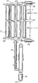
Фиг.1 показывает схематический вид сбоку станка согласно изобретению. Figure 1 shows a schematic side view of a machine according to the invention.
Фиг.2 - общий вид зоны, в которой продольно нарезаются трубчатые сердечники. Figure 2 is a General view of the zone in which tubular cores are longitudinally cut.
Сведения, подтверждающие возможность осуществления изобретения
Из фиг. 1 видно, что станок содержит пару намоточных валиков 1 и 3 на параллельных осях, расположенных рядом друг с другом, для формирования намоточной рамы 5. Над намоточной рамой расположен третий валик 9, который может перемещаться вертикально, как показано стрелкой f9. Три валика 1, 3, 9 образуют область намотки, в которой формируются рулоны из рулонного материала вокруг трубчатых сердечников А, которые вставляются, когда это требуется, в намоточную раму 5 способом, описанным ниже.Information confirming the possibility of carrying out the invention
From FIG. Figure 1 shows that the machine contains a pair of winding rollers 1 and 3 on parallel axes located next to each other to form a winding frame 5. Above the winding frame is a third roller 9, which can be moved vertically, as shown by arrow f9. Three rollers 1, 3, 9 form a winding region in which rolls of rolled material are formed around the tubular cores A, which are inserted, when required, into the winding frame 5 in the manner described below.
Рулонный материал N подается снизу через щель 11 между двумя намоточными валиками 1, 3. Вдоль траектории рулонного материала расположены разгонный валик 13 и серии резцов 14, которые действуют в комбинации с круговыми пазами, сформированными в намоточном валике 1, для продольной резки рулонного материала N на полосы, более узкие, чем общая ширина рулонного материала N. Сбоку валиков 1, 3 установлен эжекторный фартук 15, на который не оказывают воздействия законченные рулоны. The roll material N is fed from below through the slot 11 between the two winding rollers 1, 3. Along the path of the roll material are an accelerating roller 13 and a series of cutters 14, which act in combination with circular grooves formed in the winding roller 1 for longitudinal cutting of the rolled material N onto strips narrower than the total width of the roll material N. On the side of the rollers 1, 3 there is an ejector apron 15, which is not affected by the finished rolls.
На фиг.1 серии рулонов, аксиально выравненных и готовых для извлечения, показаны как R1. Рулоны R1 перемещаются от рамы 5 к эжекторному фартуку 15 при помощи качающегося рычага 17, подвешенного на оси 19 к станку, причем это качающееся перемещение контролируется приводом 18 типа поршень/цилиндр. На свободном конце качающегося рычага 17 установлен прижимной ролик 21 для воздействия на поверхность рулонов R1 и их извлечения. 1, a series of rolls axially aligned and ready for retrieval are shown as R1. The rolls R1 are moved from the frame 5 to the ejector apron 15 by means of a swing arm 17 suspended on an axis 19 from the machine, this swing motion being controlled by a piston / cylinder drive 18. At the free end of the swing arm 17, a pinch roller 21 is mounted for impacting and removing the surface of the rolls R1.
Эжекторный фартук 15 имеет небольшой наклон во внешнюю сторону и на его более низком конце расположены два цилиндра 23, 25 стороной к стороне. Цилиндр 25 установлен на фиксированной оси, тогда как ось цилиндра 23 может поворачиваться вокруг оси цилиндра 25 и ее поворотное перемещение контролируется приводом 27 типа поршень/цилиндр. Цилиндр 23 может занимать три различных положения относительно цилиндра 25, одно из которых показано сплошной линией на фиг.1, тогда как два других - пунктирными линиями и отмечены как 23Х и 23Y. Один или оба цилиндра 23, 25 моторизованы. Функция пары валиков 23, 25 более подробно будет разъяснена ниже. The ejector apron 15 has a slight tilt to the outside and at its lower end are two cylinders 23, 25 side to side. The cylinder 25 is mounted on a fixed axis, while the axis of the cylinder 23 can rotate around the axis of the cylinder 25 and its rotational movement is controlled by a piston / cylinder drive 27. The cylinder 23 can occupy three different positions relative to the cylinder 25, one of which is shown by the solid line in Fig. 1, while the other two by dashed lines and marked as 23X and 23Y. One or both cylinders 23, 25 are motorized. The function of the pair of rollers 23, 25 will be explained in more detail below.
В эжекторном фартуке 15 выполнена поперечная прорезь, вдоль которой продвигается каретка 31, которая может перемещать эжекторный фартук 15 в направлении, в основном перпендикулярном направлению, в котором рулоны прокатываются на фартуке 15. In the ejector apron 15, a transverse slot is made along which the carriage 31 advances, which can move the ejector apron 15 in the direction generally perpendicular to the direction in which the rolls are rolled on the apron 15.
Каретка 31 переносит первое сопло 33 и второе сопло 35 для подачи подходящего клея к рулонному материалу и к трубчатым намоточным сердечникам способом, описанным ниже. Каретка 31 также переносит резец 37, который разрезает рулонный материал при завершении намотки. The carriage 31 carries the first nozzle 33 and the second nozzle 35 to supply a suitable adhesive to the web material and to the tubular winding cores in the manner described below. The carriage 31 also carries a cutter 37, which cuts the web material upon completion of winding.
На противоположной от эжекторного фартука 15 стороне станка предусмотрены средства для подачи и разрезания трубок и вставки трубчатых намоточных сердечников. Эти средства содержат магазин 41 с трубками Т (изготовленными, например, из картона), подаваемыми непосредственно от машины, в которой они были изготовлены, или из большего хранилища. На нижнем конце магазина 41 вращающийся раздатчик 43, управляемый приводом 45, принимает по одной трубке Т из магазина 41 и выгружает их на пандус 47. В конце пандуса 47 расположена пара цилиндров 49, 51 стороной к стороне на параллельных осях. Цилиндр 51 установлен на фиксированной оси, тогда как цилиндр 49 может поворачиваться с его осью вокруг оси цилиндра 51. Это поворотное перемещение контролируется приводом 53 типа поршень/цилиндр. Один или оба цилиндра 49, 51 моторизованы и производят разрезание трубок Т для получения трубчатых сердечников требуемых длин способом, более подробно описанным ниже. On the side of the machine opposite from the ejector apron 15, means are provided for feeding and cutting tubes and inserting tubular winding cores. These means comprise a magazine 41 with tubes T (made, for example, from cardboard), supplied directly from the machine in which they were made, or from a larger storage. At the lower end of the magazine 41, a rotating dispenser 43, controlled by the drive 45, receives one tube T from the magazine 41 and unloads them onto the
Ниже пары цилиндров 49, 51 расположены средства 55 установки, которые поворачиваются вокруг оси намоточного валика 3, причем поворотное перемещение контролируется приводом 57 типа поршень/цилиндр. Below the pair of
Выше пары цилиндров 49, 51 расположена опора 61 с направляющей 63 типа ласточкина хвоста, проходящей крестообразно относительно рулонного материала N. Ползуны 65 позиционированы и заблокированы в точках вдоль направляющей 63 и каждый из них переносит свой собственный инструмент 67 продольной резки в форме режущего диска, который может быть поднят и опущен, как показано двойной стрелкой f67. Каждый режущий диск смонтирован на своем собственном ведущем вале. Above the pair of
Станок, как он описан выше, работает следующим образом: раздатчик 43 принимает трубку Т из магазина 41 и выгружает ее на пандус 47; трубка Т сама позиционируется в раме между цилиндрами 49 и 51 и в этом положении при помощи привода 73 цилиндрическая оправка 71 (см. также фиг.2) вставляется в трубку Т. Диаметр оправки 71 немного меньше внутреннего диаметра трубки Т с тем, чтобы ее можно было легко вставлять и извлекать. The machine, as described above, operates as follows: the distributor 43 receives the tube T from the magazine 41 and unloads it onto the
Как только оправка 71 вставлена в трубку Т, инструменты 67 опускаются и надавливают на трубку для проникновения по толщине картона (или другого подходящего материала, например пластмассы), формирующего трубку Т. Цилиндры 49, 51 вращаются для поворота трубки Т и оправки внутри нее, которая для этой цели поддерживается консольным образом на опорных подшипниках, обеспечивающих ее легкое вращение вокруг собственной оси. Once the
Таким образом трубки Т разрезаются инструментами 67, которые действуют в комбинации с оправкой 71, на трубчатые сердечники А укороченной длины, соответствующей аксиальной длине рулонов, которые требуется изготовить. Присутствие оправки внутри трубки Т обеспечивает быстрое и точное разрезание, производимое без деформации трубчатого материала. In this way, the tubes T are cut by tools 67, which act in combination with the
Как упоминалось выше, инструменты 67 могут производить круговые перфорации в отличие от полного разрезания по линиям разъединения трубки Т. Перфорации разделяют трубку на трубчатые сердечники, которые, однако, остаются прикрепленными один к другому по перфорациям и разделяются, как только рулонный материал наматывается на них. As mentioned above, tools 67 can produce circular perforations, in contrast to complete cutting along the separation lines of the T tube. The perforations divide the tube into tubular cores, which, however, remain attached to each other along the perforations and separate as soon as the rolled material is wound on them.
В дополнение к упомянутому разрезанию инструменты 67 также производят два боковых разрезания для исключения обрезков от головной и хвостовой частей трубки. Затем обрезки удаляются, например, при помощи средств всасывания (не показаны). In addition to the above-mentioned cutting, the tools 67 also make two side cuts to exclude cuts from the head and tail of the tube. Then the scraps are removed, for example, by means of suction (not shown).
Когда трубка Т разделена на серии трубчатых сердечников А (отделенных один от другого или объединенных линиями перфораций, произведенными инструментами 67), оправка 71 аксиально извлекается при помощи привода 73 для выгрузки трубчатых сердечников А. Они выгружаются на средства 55 установки, которые находятся в положении, показанном сплошными линиями на фиг.1. Выгрузка сердечников А на средства 55 установки осуществляется путем поворота цилиндра 49 от привода 53 вокруг оси цилиндра 51. When the tube T is divided into a series of tubular cores A (separated from one another or combined by perforation lines made by tools 67), the
Когда разрезанные трубчатые сердечники достигают положения А1 на средствах установки, последние, в свою очередь, поворачиваются приводом 57 в направлении положения, показанного пунктирными линиями и отмеченного как 55Х, где трубчатые сердечники А выгружены в положении А2 на раму 5 между валиками 1, 3. На этом этапе валики 1 и 3 временно стационарны и валик 9 находится в поднятом положении, показанном как 9Х пунктирными линиями на фиг. 1. Рулонный материал N обматывается частично вокруг периферии намоточного валика 1 и, следовательно, трубчатые сердечники А приходят в контакт с рулонным материалом, когда они выгружены на раму 5. When the cut tubular cores reach position A1 on the installation means, the latter, in turn, are rotated by the actuator 57 in the direction of the position shown by dashed lines and marked as 55X, where the tubular cores A are unloaded in position A2 on the frame 5 between the rollers 1, 3. On At this stage, the rollers 1 and 3 are temporarily stationary and the roller 9 is in the raised position, shown as 9X by dashed lines in FIG. 1. The roll material N is wound partially around the periphery of the winding roller 1 and, therefore, the tubular cores A come into contact with the roll material when they are unloaded on the frame 5.
Положение резцов 14 и режущих инструментов 67 таково, что каждый трубчатый сердечник А будет соответствовать одной из полос, полученных путем продольного разрезания рулонного материала N резцами 14. The position of the cutters 14 and cutting tools 67 is such that each tubular core A will correspond to one of the strips obtained by longitudinal cutting of the roll material N with cutters 14.
Когда трубчатые сердечники А располагаются в положении А2, они обеспечивают линию клея, нанесенного соплом 35, установленным на каретке 31, которая для этой цели продвигается вдоль прорези в фартуке 15. Серии сопел 16 в эжекторном фартуке 15 подают струю воздуха, которая заворачивает полученный край материала вокруг трубчатых сердечников в положении 2. Затем валик 9 опускается до контакта с поверхностями этих трубчатых сердечников, которые таким образом контактируют в тремя валиками 1, 3, 9. Когда три валика 1, 3, 9 начинают поворачиваться в одинаковом направлении, трубчатые сердечники А поворачиваются и соответственно клей, нанесенный на них, контактирует с рулонным материалом, который в результате начинает наматываться на сердечники. When the tubular cores A are in position A2, they provide a line of glue applied by a nozzle 35 mounted on the carriage 31, which for this purpose moves along the slot in the apron 15. A series of nozzles 16 in the ejector apron 15 serves a stream of air that wraps the received edge of the material around the tubular cores in position 2. Then, the roller 9 is lowered to contact the surfaces of these tubular cores, which thus contact the three rollers 1, 3, 9. When the three rollers 1, 3, 9 begin to rotate in the same In the opposite direction, the tubular cores A are rotated and, accordingly, the adhesive applied to them is in contact with the roll material, which as a result begins to be wound on the cores.
Поскольку вращение намоточных валиков 1, 3, 9 продолжается, формируются серии рулонов R1, каждый на своем собственном трубчатом сердечнике А. Поскольку рулоны формируются на сердечниках А в намоточной раме 5, новая трубка Т выгружается на цилиндры 49, 51 для разделения на новые серии трубчатых сердечников А, которые будут вставлены в раму 5 на последующем цикле намотки. As the rotation of the winding rollers 1, 3, 9 continues, a series of rolls R1 are formed, each on its own tubular core A. Since the rolls are formed on the cores A in the winding frame 5, a new tube T is unloaded on
При завершении намотки валики 1, 3 и 9 останавливаются и качающийся рычаг 17 при помощи привода 18 поворачивается по часовой стрелке, как показано стрелкой fl7, для выведения серий рулонов R1 на эжекторный фартук 15. Рулоны R1 выкатываются на фартук 15 и останавливаются на краю последнего, когда они сталкиваются с цилиндрами 25, 23, причем последние находятся для этой цели в положении 23Y. R2 показывает положение рулонов R, когда они завершают выкатывание на эжекторный фартук 15. When winding is completed, the rollers 1, 3 and 9 stop and the swinging lever 17 is turned clockwise by the drive 18, as shown by arrow fl7, to bring out a series of rolls R1 on the ejector apron 15. The rolls R1 are rolled onto the apron 15 and stop at the edge of the latter, when they collide with cylinders 25, 23, the latter being in position 23Y for this purpose. R2 shows the position of the rolls R when they complete rolling out onto the ejector apron 15.
При достижении этого положения рулонный материал N все еще связан с рулонами R2 и должен быть отрезан таким образом, чтобы намотка могла начаться на следующих сериях трубчатых сердечников А, которые доставляются в намоточную раму 5 способом, описанным выше. Upon reaching this position, the roll material N is still bonded to rolls R2 and must be cut so that winding can begin on the following series of tubular cores A, which are delivered to the winding frame 5 in the manner described above.
В этом положении рулона каретка 31 производит крестообразное движение таким путем, чтобы выполнялись одновременно три действия:
1. для подачи при помощи сопла 33 линии клея на область рулонного материала, расположенную между траекторией каретки 31 и рулонами в положении R2,
2. для разрезания рулонного материала крест-накрест при помощи резца 37, и
3. для подачи линии клея при помощи сопла 35 на новые трубчатые сердечники, которые тем временем были помещены в раму 5 в положении А2 способом, описанным выше.In this position of the roll, the carriage 31 makes a crosswise movement in such a way that three actions are performed simultaneously:
1. for feeding by means of a nozzle 33 glue lines to the area of the roll material located between the path of the carriage 31 and the rolls in position R2,
2. for cutting the roll material crosswise with a cutter 37, and
3. to feed the glue line using the nozzle 35 to the new tubular cores, which in the meantime were placed in the frame 5 in position A2 in the manner described above.
После того, как рулонный материал был разрезан резцом 37, рулоны R2 вращаются таким образом, чтобы также намотать хвостовой конец рулонного материала, образованный при операции резания резцом 37. Поскольку хвостовой конец переносит клей, поданный соплом 33, вращение рулонов R2 также вызывает приклеивание и закрывание хвостового конца этих рулонов. After the roll material has been cut by the cutter 37, the R2 rolls are rotated so as to also wind the tail end of the roll material formed during the cutting operation of the cutter 37. Since the tail end transfers the glue supplied by the nozzle 33, the rotation of the R2 rolls also causes gluing and closing tail end of these rolls.
Для этой цели цилиндр 23 перемещается в положение 23Х, при котором оси цилиндра 23, 25 в основном находятся в более высоком положении, выравниваясь в горизонтальной плоскости. Таким образом рулоны R2 поддерживаются только цилиндрами 23, 25, а не эжекторным фартуком 15, это означает, что вращение цилиндров 23, 25 против часовой стрелки будет закрывать свободный конец рулонов R2. For this purpose, the cylinder 23 moves to position 23X, in which the axes of the cylinder 23, 25 are generally in a higher position, aligned in the horizontal plane. Thus, the R2 coils are only supported by the cylinders 23, 25, and not the ejector apron 15, which means that counterclockwise rotation of the cylinders 23, 25 will close the free end of the R2 coils.
Затем рулоны, теперь законченные и приклеенные, выгружаются на конвейерную ленту или другое подходящее устройство (не показаны) путем перемещения цилиндра 23 в положение, показанное сплошными линиями на фиг.1. Альтернативно выгрузка может производиться путем аксиального толкания рулона выталкивателем, который продвигается между цилиндрами 23, 25 параллельно их осям, причем в этом случае может быть немного увеличено расстояние между цилиндрами 23, 25. Then the rolls, now finished and glued, are discharged onto a conveyor belt or other suitable device (not shown) by moving the cylinder 23 to the position shown by the solid lines in FIG. 1. Alternatively, unloading can be done by axially pushing the roll with an ejector that moves between the cylinders 23, 25 parallel to their axes, in which case the distance between the cylinders 23, 25 can be slightly increased.
При относительно длительном времени намотки, требуемом для формирования рулонов R большого диаметра, операции намотки свободных концов рулонов в положении R2 и продольной резки трубок Т выполняются вне намотки рулонов в раме 5. With a relatively long winding time required for the formation of rolls R of large diameter, the winding operations of the free ends of the rolls in position R2 and the longitudinal cutting of the tubes T are performed outside the winding of the rolls in frame 5.
Понятно, что чертеж показывает только пример исключительно практической демонстрации изобретения, который далее может варьироваться в формах и устройствах без выхода за рамки той концепции, на которой базируется изобретение. Любые отсылочные позиции в прилагаемых пунктах формулы присутствуют для облегчения прочтения пунктов со ссылкой на описание и чертеж и не ограничивают объем защиты, представленный этими пунктами. It is understood that the drawing shows only an example of an exceptionally practical demonstration of the invention, which may further vary in forms and devices without going beyond the concept on which the invention is based. Any reference items in the attached claims are present to facilitate reading of the paragraphs with reference to the description and drawing and do not limit the scope of protection represented by these paragraphs.
Claims (5)
Applications Claiming Priority (2)
| Application Number | Priority Date | Filing Date | Title |
|---|---|---|---|
| IT97FI000166A IT1294817B1 (en) | 1997-07-11 | 1997-07-11 | REWINDING MACHINE - CUTTER FOR THE PRODUCTION OF ROLLS OF TAPE MATERIAL AND RELATED METHOD |
| ITFI97A000166 | 1997-07-11 |
Publications (2)
| Publication Number | Publication Date |
|---|---|
| RU2000103301A RU2000103301A (en) | 2002-01-10 |
| RU2189347C2 true RU2189347C2 (en) | 2002-09-20 |
Family
ID=11352201
Family Applications (1)
| Application Number | Title | Priority Date | Filing Date |
|---|---|---|---|
| RU2000103301/12A RU2189347C2 (en) | 1997-07-11 | 1998-07-02 | Rewinding-and-cutting machine tool for making rolls from roll material and method of roll making |
Country Status (17)
| Country | Link |
|---|---|
| US (1) | US6129304A (en) |
| EP (1) | EP0994820B1 (en) |
| JP (1) | JP4480265B2 (en) |
| KR (1) | KR100398732B1 (en) |
| CN (1) | CN1092128C (en) |
| AR (1) | AR005216A1 (en) |
| AT (1) | ATE214031T1 (en) |
| AU (1) | AU8240298A (en) |
| BR (1) | BR9810692A (en) |
| CA (1) | CA2294227C (en) |
| DE (1) | DE69804103T2 (en) |
| ES (1) | ES2173597T3 (en) |
| IT (1) | IT1294817B1 (en) |
| PL (1) | PL187197B1 (en) |
| RU (1) | RU2189347C2 (en) |
| WO (1) | WO1999002439A1 (en) |
| ZA (1) | ZA985860B (en) |
Cited By (2)
| Publication number | Priority date | Publication date | Assignee | Title |
|---|---|---|---|---|
| RU2548880C2 (en) * | 2009-10-28 | 2015-04-20 | Джорджия-Пэсифик Консьюмер Продактс Лп | Methods, systems and articles including sheet-like articles |
| RU2651301C2 (en) * | 2013-04-09 | 2018-04-19 | Блю Солюшнз | Device for separating at least two adjacent strands of material and system including such device |
Families Citing this family (47)
| Publication number | Priority date | Publication date | Assignee | Title |
|---|---|---|---|---|
| IT1308270B1 (en) * | 1999-04-12 | 2001-12-10 | Celli Spa | PLANT AND METHOD FOR THE PREPARATION OF SPINDLES AND WRAPPING CORES FOR REWINDING MACHINES OR SIMILAR |
| DE19960000A1 (en) * | 1999-12-13 | 2001-07-05 | Voith Sulzer Papiertech Patent | Roll winding device, in particular for a roll cutting machine |
| US6422501B1 (en) * | 2000-11-27 | 2002-07-23 | Paper Converting Machine Company | Core infeed apparatus for winder |
| US20020139228A1 (en) * | 2001-03-27 | 2002-10-03 | Newell Operating Company | Perforated roller cover and methods of manufacture thereof |
| EP1344735B1 (en) * | 2002-03-12 | 2007-08-29 | DOLCI EXTRUSION S.r.l | Winder for film of plastic material |
| US7238236B2 (en) * | 2002-11-14 | 2007-07-03 | Kimberly-Clark Worldwide, Inc. | Apparatus for increasing tail adhesion of wet rolls |
| ITFI20030036A1 (en) * | 2003-02-12 | 2004-08-13 | Perini Fabio Spa | REWINDER MACHINE FOR THE PRODUCTION OF ROLLS |
| US7107888B2 (en) * | 2003-03-07 | 2006-09-19 | Bay West Paper Corporation | Core reduction method and apparatus |
| US7222813B2 (en) * | 2005-03-16 | 2007-05-29 | Chan Li Machinery Co., Ltd. | Multiprocessing apparatus for forming logs of web material and log manufacture process |
| US7392961B2 (en) | 2005-08-31 | 2008-07-01 | The Procter & Gamble Company | Hybrid winder |
| US7455260B2 (en) | 2005-08-31 | 2008-11-25 | The Procter & Gamble Company | Process for winding a web material |
| US7546970B2 (en) | 2005-11-04 | 2009-06-16 | The Procter & Gamble Company | Process for winding a web material |
| US8800908B2 (en) | 2005-11-04 | 2014-08-12 | The Procter & Gamble Company | Rewind system |
| US8459586B2 (en) | 2006-03-17 | 2013-06-11 | The Procter & Gamble Company | Process for rewinding a web material |
| US7559503B2 (en) | 2006-03-17 | 2009-07-14 | The Procter & Gamble Company | Apparatus for rewinding web materials |
| BRPI0721822B1 (en) * | 2007-07-04 | 2018-11-06 | Celli Nonwovens Spa | system and method for preparing winding chucks |
| CN102923510B (en) * | 2007-07-04 | 2015-11-04 | A.塞利无纺股份公司 | For preparing winding mandrel to form the system and method for reel |
| DE102008018890A1 (en) * | 2008-04-14 | 2009-10-29 | Ancient Energy Gmbh & Co. Kg | Apparatus and method for winding web-shaped materials |
| IT1391147B1 (en) * | 2008-07-10 | 2011-11-18 | Guglielmo Biagiotti | APPARATUS, AND ITS METHOD, FOR THE TRANSFORMATION OF ADJACENT TAPES OF FLEXIBLE MATERIAL. |
| US8172982B2 (en) * | 2008-12-22 | 2012-05-08 | Kimberly-Clark Worldwide, Inc. | Conductive webs and process for making same |
| US8162251B2 (en) | 2009-07-24 | 2012-04-24 | The Procter & Gamble Company | Hybrid winder |
| US8157200B2 (en) | 2009-07-24 | 2012-04-17 | The Procter & Gamble Company | Process for winding a web material |
| CH705226A2 (en) * | 2011-07-05 | 2013-01-15 | Swiss Winding Inventing Ag | Winder. |
| US8794562B2 (en) * | 2011-10-13 | 2014-08-05 | The Procter & Gamble Company | Mandrel cupping assembly |
| US8783599B2 (en) * | 2011-10-13 | 2014-07-22 | The Procter & Gamble Company | Process for rewinding a web material |
| US8783598B2 (en) | 2011-10-13 | 2014-07-22 | The Procter & Gamble Company | Web rewinding apparatus |
| US8973858B2 (en) * | 2012-04-18 | 2015-03-10 | The Procter & Gamble Company | Web rewinding apparatus |
| US8915462B2 (en) * | 2012-04-18 | 2014-12-23 | The Procter & Gamble Company | Mandrel cupping assembly |
| KR101275603B1 (en) | 2012-08-04 | 2013-06-17 | 김응섭 | Winding reel device for slitter |
| US8915461B2 (en) | 2012-08-07 | 2014-12-23 | The Procter & Gamble Company | Mandrel cupping assembly |
| US9045303B2 (en) | 2012-08-07 | 2015-06-02 | The Procter & Gamble Company | Mandrel cupping assembly |
| US8910897B2 (en) | 2012-08-07 | 2014-12-16 | The Procter & Gamble Company | Web rewinding apparatus |
| US9027870B2 (en) | 2012-08-07 | 2015-05-12 | The Procter & Gamble Company | Web rewinding apparatus |
| US8925853B2 (en) | 2012-08-27 | 2015-01-06 | The Procter & Gamble Company | Mandrel cupping assembly |
| US8919687B2 (en) | 2012-08-27 | 2014-12-30 | The Procter & Gamble Company | Mandrel cupping assembly |
| ITMI20131576A1 (en) * | 2013-09-25 | 2015-03-26 | Colines Spa | LOADER FOR ANIME AND EXHAUST AUTOMATIC COILS IN A PLASTIC FILM WINDING MACHINE |
| CN103659867B (en) * | 2013-12-23 | 2015-11-18 | 东莞市新望包装机械有限公司 | A kind of four axle transposition platforms of cutting based on adhesive tape |
| CN104044944B (en) * | 2014-05-27 | 2016-07-27 | 洛阳一海包装材料有限公司 | A kind of coextrusion film blowing unit wrap-up |
| US9809417B2 (en) | 2015-08-14 | 2017-11-07 | The Procter & Gamble Company | Surface winder |
| US10427902B2 (en) | 2016-03-04 | 2019-10-01 | The Procter & Gamble Company | Enhanced introductory portion for a surface winder |
| US10442649B2 (en) | 2016-03-04 | 2019-10-15 | The Procter & Gamble Company | Surface winder for producing logs of convolutely wound web materials |
| US10427903B2 (en) | 2016-03-04 | 2019-10-01 | The Procter & Gamble Company | Leading edge device for a surface winder |
| CN106241452A (en) * | 2016-10-19 | 2016-12-21 | 郑州纺机工程技术有限公司 | A kind of wet up-coiler being applicable to non-weaving cloth cotton pads spun lacing production line |
| CN109279406A (en) * | 2018-11-23 | 2019-01-29 | 桂珏智能科技(上海)有限公司 | A kind of non-woven fabrics rouleau rewinding machine |
| IT202000007171A1 (en) | 2020-04-03 | 2021-10-03 | Perini Fabio Spa | A PACK OF PROTECTIVE MASKS, A METHOD AND A MACHINE FOR THEIR PRODUCTION |
| DE102020120792A1 (en) * | 2020-08-06 | 2022-02-10 | PF-Schweißtechnologie GmbH | Articulated knife holder |
| CN113104623A (en) * | 2021-04-08 | 2021-07-13 | 南京轩昱逸塑料科技有限公司 | Freshness protection package production preparation system of processing |
Family Cites Families (3)
| Publication number | Priority date | Publication date | Assignee | Title |
|---|---|---|---|---|
| US4422588A (en) * | 1981-09-28 | 1983-12-27 | The Black Clawson Company | Slitter-rewinder system |
| US4695006A (en) * | 1985-08-12 | 1987-09-22 | Minnesota Mining And Manufacturing | Paper converting machine |
| JP3609170B2 (en) * | 1995-10-05 | 2005-01-12 | 富士写真フイルム株式会社 | Web winding device |
-
1997
- 1997-07-11 IT IT97FI000166A patent/IT1294817B1/en active IP Right Grant
-
1998
- 1998-07-02 BR BR9810692-9A patent/BR9810692A/en not_active IP Right Cessation
- 1998-07-02 WO PCT/IT1998/000185 patent/WO1999002439A1/en active IP Right Grant
- 1998-07-02 RU RU2000103301/12A patent/RU2189347C2/en not_active IP Right Cessation
- 1998-07-02 ES ES98932499T patent/ES2173597T3/en not_active Expired - Lifetime
- 1998-07-02 KR KR10-2000-7000174A patent/KR100398732B1/en not_active IP Right Cessation
- 1998-07-02 AT AT98932499T patent/ATE214031T1/en not_active IP Right Cessation
- 1998-07-02 JP JP2000501976A patent/JP4480265B2/en not_active Expired - Lifetime
- 1998-07-02 DE DE69804103T patent/DE69804103T2/en not_active Expired - Lifetime
- 1998-07-02 CN CN98806011A patent/CN1092128C/en not_active Expired - Fee Related
- 1998-07-02 EP EP98932499A patent/EP0994820B1/en not_active Expired - Lifetime
- 1998-07-02 US US09/297,222 patent/US6129304A/en not_active Expired - Fee Related
- 1998-07-02 PL PL98337898A patent/PL187197B1/en not_active IP Right Cessation
- 1998-07-02 CA CA002294227A patent/CA2294227C/en not_active Expired - Fee Related
- 1998-07-02 AU AU82402/98A patent/AU8240298A/en not_active Abandoned
- 1998-07-03 ZA ZA985860A patent/ZA985860B/en unknown
- 1998-07-10 AR ARP980103353A patent/AR005216A1/en unknown
Cited By (6)
| Publication number | Priority date | Publication date | Assignee | Title |
|---|---|---|---|---|
| RU2548880C2 (en) * | 2009-10-28 | 2015-04-20 | Джорджия-Пэсифик Консьюмер Продактс Лп | Methods, systems and articles including sheet-like articles |
| US9227374B2 (en) | 2009-10-28 | 2016-01-05 | Georgia-Pacific Consumer Products Lp | Methods, systems and products involving sheet products |
| US9272483B2 (en) | 2009-10-28 | 2016-03-01 | Georgia-Pacific Consumer Products Lp | Methods, systems and products involving sheet products |
| US9296173B2 (en) | 2009-10-28 | 2016-03-29 | Georgia-Pacific Consumer Products Lp | Methods, systems and products involving sheet products |
| US9296172B2 (en) | 2009-10-28 | 2016-03-29 | Georgia-Pacific Consumer Products Lp | Methods, systems and products involving sheet products |
| RU2651301C2 (en) * | 2013-04-09 | 2018-04-19 | Блю Солюшнз | Device for separating at least two adjacent strands of material and system including such device |
Also Published As
| Publication number | Publication date |
|---|---|
| CA2294227A1 (en) | 1999-01-21 |
| ZA985860B (en) | 1998-10-05 |
| KR100398732B1 (en) | 2003-09-19 |
| BR9810692A (en) | 2000-09-05 |
| DE69804103D1 (en) | 2002-04-11 |
| KR20010021616A (en) | 2001-03-15 |
| US6129304A (en) | 2000-10-10 |
| DE69804103T2 (en) | 2002-10-17 |
| EP0994820B1 (en) | 2002-03-06 |
| WO1999002439A1 (en) | 1999-01-21 |
| IT1294817B1 (en) | 1999-04-15 |
| CA2294227C (en) | 2006-02-14 |
| EP0994820A1 (en) | 2000-04-26 |
| JP4480265B2 (en) | 2010-06-16 |
| CN1259920A (en) | 2000-07-12 |
| CN1092128C (en) | 2002-10-09 |
| ITFI970166A1 (en) | 1999-01-11 |
| PL187197B1 (en) | 2004-05-31 |
| JP2001509466A (en) | 2001-07-24 |
| AR005216A1 (en) | 1999-04-28 |
| AU8240298A (en) | 1999-02-08 |
| PL337898A1 (en) | 2000-09-11 |
| ATE214031T1 (en) | 2002-03-15 |
| ES2173597T3 (en) | 2002-10-16 |
Similar Documents
| Publication | Publication Date | Title |
|---|---|---|
| RU2189347C2 (en) | Rewinding-and-cutting machine tool for making rolls from roll material and method of roll making | |
| US8210462B2 (en) | Center/surface rewinder and winder | |
| US4775110A (en) | Method of and apparatus for the automatic winding of a web of sheet material | |
| KR100202227B1 (en) | Rewinder for producing log of web material, selectively with or without a winding core | |
| US5909856A (en) | Duplex slitter/rewinder with automatic splicing and surface/center winding | |
| JPS59167440A (en) | Hoisting device for web divided in longitudinal direction and method in case of exchange of roll and sleeve | |
| US6908525B2 (en) | Apparatus for forming a roll of contaminant removal tape and methods of forming rolls of contaminant removal tape | |
| JP3597180B2 (en) | Web winding method and apparatus | |
| JP7263510B2 (en) | Machine and method for providing rolls of material for use in sheet form, such as coreless type aluminum, especially food grade aluminum | |
| EP1456104B1 (en) | Apparatus for web cut-off in a rewinder | |
| JPH101241A (en) | Manufacture of coreless roll paper and core drawing device used therefor | |
| EP0607525A1 (en) | Cut-off and transference mechanism for rewinder | |
| JPH072394A (en) | Method and device for winding up in coreless form | |
| US6406417B1 (en) | Device for continuously winding up longitudinally cut paper webs with rolls changed automatically at the machine speed | |
| RU2781647C2 (en) | Machine and method for production of coreless rolls of material intended for use in form of sheet, in particular aluminum one, intended for use for food products | |
| FI125686B (en) | Method and arrangement in connection with a fiber web roller cutter | |
| CA1158154A (en) | Web transfer apparatus | |
| JPH07223193A (en) | Paper roll cutting device | |
| JP2002187656A (en) | Web winding device | |
| JPH10175760A (en) | Paper roll end retaining device of web take-up device |
Legal Events
| Date | Code | Title | Description |
|---|---|---|---|
| MM4A | The patent is invalid due to non-payment of fees |
Effective date: 20060703 |