JP3761685B2 - Laser processing equipment - Google Patents
Laser processing equipment Download PDFInfo
- Publication number
- JP3761685B2 JP3761685B2 JP24900497A JP24900497A JP3761685B2 JP 3761685 B2 JP3761685 B2 JP 3761685B2 JP 24900497 A JP24900497 A JP 24900497A JP 24900497 A JP24900497 A JP 24900497A JP 3761685 B2 JP3761685 B2 JP 3761685B2
- Authority
- JP
- Japan
- Prior art keywords
- tape
- workpiece
- laser processing
- laser
- piercing
- Prior art date
- Legal status (The legal status is an assumption and is not a legal conclusion. Google has not performed a legal analysis and makes no representation as to the accuracy of the status listed.)
- Expired - Fee Related
Links
Images


Description
【0001】
【発明の属する技術分野】
この発明は、レーザ加工装置に関する。
【0002】
【従来の技術】
従来、レーザ加工装置でワークに切断加工を行う際、ピアス加工という工程が必要となる。ピアス加工とは、レーザ光をワークに局部的に照射し、ワークを溶融させ、穴を貫通させる工程である。
【0003】
ピアス加工において、穴が貫通するまでの間は、ワークの溶融物が飛散し、ワークの表面に付着する。すなわち、ピアス加工中の溶融物がワークの表面にまで飛散、付着することにより、ワークの表面に傷が発生したり、不要且つ有害な盛り上がりが発生したりすることがある(俗称ヒゲと呼んでいる)。この現象は特にアルミニウム材やステンレス材の加工の際に顕著に現れると共に、このヒゲの現象が生じると、加工不良が生じ易くなるという問題がある。
【0004】
上記の問題点を解決するために、ワーク特に鏡面のステンレスにレーザ加工を行う場合には、ワークの表面にビニールを貼り、全ピアス加工を行った後にビニールを外してレーザ加工(切断加工)を行うことが知られている。
【0005】
【発明が解決しようとする課題】
ところで、上述した従来のワークにビニールを貼ったり、外したりすることは作業に手間がかかると共に大変面倒なものであった。
【0006】
この発明の目的は、ピアス加工から切断加工まで一貫して自動的にレーザ加工を行う際、ピアス加工中に、ワーク上に、傷、盛り上がり等を生じさせるのを防ぐようにすると共に作業者に手間をかけないようにしたレーザ加工装置を提供することにある。
【0007】
【課題を解決するための手段】
本発明は、前述したごとき問題に鑑みてなされたもので、一対の支持アームの上部を、レーザ加工ヘッドに上下に回動可能に装着して設け、前記一方の支持アームにテープ供給リールを回転可能に設けると共に他方の支持アームにテープ巻き取りリールを設け、前記各支持アームの下部にそれぞれ上下に揺動可能に設けたテープ押えアームの先端部に、前記テープ供給リールから前記巻き取りリールに巻き取られるテープを案内するガイドローラを設け、前記レーザ加工ヘッドの先端レーザ照射部と加工すべきワークとの間に前記テープが位置し、前記レーザ加工ヘッドの下降によって前記テープが前記ワークの表面に接触して上向きの反力を受けたとき、前記各テープ押えアームが僅かに上方に回動可能に構成してあることを特徴とするものである。
【0015】
【発明の実施の形態】
以下、この発明の実施の形態を図面に基づいて詳細に説明する。
【0016】
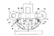
図1および図2を参照するに、上下動可能なレーザ加工ヘッド1の相対向した側面には結合ブロック3R,3Lが設けられており、この結合ブロック3R,3Lには水平方向に軸穴5R,5Lが形成されている。この軸穴5R,5Lには支持アーム回転軸7R,7Lが装着されている。この支持アーム回転軸7R,7Lには一対の支持アーム9R,9Lの上部が回転可能に装着されている。
【0017】
この各支持アーム9Rと9Lとは連結体としての連結プレート11で連結されていると共に支持アーム9Lの上部には退避用モータ13が設けられている。
【0018】
前記支持アーム9R,9Lのほぼ中央部には外側へ向けて突出部15R,15Lが一体化されており、この突出部15Rには軸17でカバー部材としてテープTが一定量巻かれたテープ供給リール19が回転可能に支承されている。また、前記突出部15Lには回転用モータ21に連結されたテープ巻き取りリール23が設けられている。
【0019】
前記支持アーム9R,9Lの下部にはそれぞれ回転可能なガイドローラ25,27がピン29,31で設けられていると共に、ピン29,31にはテープ押えアーム33,35が揺動可能に設けられている。このテープ押さえアーム33,35の一端にはガイドローラ37,39が設けられていると共にテープ押さえアーム33,35の他端と支持アーム9R,9Lの一部との間にはスプリング41,43が介在されており、ストッパピン45R,45Lで内側へいかないように拘束されている。
【0020】
上記構成により、退避用モータ13を駆動せしめると、支持アーム9R,9Lが同期して図1の状態から90度回動されることになる。また、回転用駆動モータ21を駆動せしめると、巻き取りリール23が回転してテープ供給リール19に巻かれたテープTはガイドローラ25,37,39,27を経てテープ巻き取りリール23に巻かれるものである。
【0021】
次に、この構成のレーザ加工装置の加工に工程について順を追って説明する。
【0022】
(工程1)図3はピアス加工の開始直前の状態を示し、テープTは加工ヘッド1の先端レーザ照射部とワークWの間にある(即ち、動作位置)。
【0023】
この状態から加工ヘッド1は下降を開始し、ピアス加工に適した位置に停止し図4の状態となる。停止した状態では、ガイドローラ37,39に支持されたテープTが、ワークWの表面に接触し、ワークWのピアス加工される部分の周囲を覆うように位置付けられる。
【0024】
この時、ガイドローラ37,39がワークWの表面から上向きの反力を受け、テープ押さえアーム33,35が、最初の位置からそれぞれ、時計周りと反時計周りにわずかの角度だけ回転した状態になるように調整されていることが望ましい。
【0025】
必要に応じて、テープTがワークWの表面に接触していることをセンサ等で確認してもよい。この確認は例えば、テープ押さえアーム33,35の回転をリミットスイッチ等のセンサで検出する方法で行ってもよい。
【0026】
(工程2)この位置で加工ヘッド1からピアス加工に応じたレーザ光が照射され、公知のピアス加工が行われる。この工程中は図5に示すようにワークWの表面がテープTにより覆われているため、レーザLB光により加熱溶融されたスパッタSが飛散してテープT上に付着や、傷が発生することがあっても、ワークWの表面に付着したり、表面を傷つけたりすることはない。即ち、ワークWの表面の付着物、傷を防止することができる。
【0027】
(工程3)ピアス加工が終了すると、加工ヘッド1が上昇を始め、テープTはワークWに表面から離れる。この時、図6のようにテープT上の付着物や傷はテープTと共にワークWの表面から除去される。
【0028】
テープTがワークWの表面から離れた後、または、加工ヘッド1が充分上に上昇した後、退避用モータ13が動作して、支持アーム9R,9Lが回転され、90度回転したところで停止し、図7に示したような退避位置になる。
【0029】
(工程4)図7の状態では、テープTは加工ヘッド1から遠ざけてあり、且つ、加工ヘッド1より上方に有るため、レーザ加工ヘッド1の機能は従来のレーザ加工ヘッドと何ら変わることが無く、従来の切断工程に入ることが出来る。即ち、加工ヘッド1が切断工程に適した位置まで下降し、レーザ光をワークWに照射して切断が行われることになる。
【0030】
(工程5)切断加工終了後、加工ヘッド1が上昇し、退避用モータ13が再び動作し、支持アーム9R,9Lを動作位置に戻す。テープ巻き取りリール19がステップモータ21によって回転駆動され、テープTが適当な長さだけ巻き取られる。この巻き取り長さは、ピアス加工によってテープT上に発生すると見込まれる付着物、傷の範囲の直径より大きく設定される。巻き取りによってテープT上の付着物、傷はテープTと共に移動し、運び去られ、テープTの新しい部分が加工ヘッド1のレーザ光照射部の真下に位置することになり、全体は図3の状態に戻り、再び(工程1)が開始可能になっている。
【0031】
前記テープTの巻き取りは、(工程5)の時期に限定されることなく、(工程3)において、加工ヘッド1の上昇が終了た時点から(工程5)の終了時点までの間であっても良い。
【0032】
以上に説明したこの発明の実施の形態によれば、ピアス加工時にワークWの表面に溶融物が飛散して付着したり、表面を傷つけたりすることが防止でき、且つ、切断加工においては従来と何ら変わらない条件で加工できるため、ピアス加工から、切断加工に至るまで全て自動的に進めることが出来る。
【0033】
前記発明の実施の形態においては、(工程3)においてテープTを退避させる形態は、支持アーム9R,9L等を軸穴5R,5Lの周りに約90度回転させ、テープT全体を加工ヘッド1の先端から遠ざけるもので説明したが、他の実施の形態はテープTの退避の形態と全く別の機能を提供する。
【0034】
図8には別の実施の形態が示されている。図8において、支持アーム9R,9Lに支えられたテープ状カバー部材Tの供給、支持、巻き取りに関する機構は上述した例に示した機構と全く同じであるので、同じ符号を符し、重複する説明を省略する。
【0035】
テープTには図9に示されているように、あらかじめ充分大きな円形のにげ穴47が、その幅の中心線上に、テープTの長手方向へ定められた間隔に開けられている。にげ穴47の間の距離ピアス加工によってテープT上に発生すると見込まれる付着、傷の範囲の直径より大きく設定される。
【0036】
支持アーム9R,9Lは図8に示されているように、連結体49によって一体的に連結、支持されている。連結体49は、1軸アクチュエータによって、加工ヘッド1に対し、加工ヘッド1の発射するレーザの光軸に平行に移動可能である。そして、加工ヘッド1に対し、連結体49及び該連結体49に支持された支持アーム9R,9L及びテープTの供給、支持、巻き取り機構は二つの定められた位置関係を採ることが出来る。第1の位置関係では、加工ヘッド1の先端とワークWの表面の間にテープTがあり、且つ、レーザの光軸LBがテープTの幅のほぼ中央を貫くように配置される。この位置関係を動作位置と呼ぶ。第2の位置関係では、テープTの面は、加工ヘッド1の先端より上方に位置し、これを退避位置と呼ぶ。
【0037】
テープTの供給、支持、巻き取り機構は、テープTのにげ穴47の位置を検出する機構を持つ。
【0038】
以下、この構成のレーザ加工装置の加工の工程について順を追って説明する。各工程の番号は上述した実施の形態における同じ番号の工程に対応する。
【0039】
(工程1)ピアス加工の準備段階をなす工程で、図8に示した状態の動作位置にある。にげ穴検出機構により、にげ穴47の位置を確認しながら、ステッピングモータ21が必要な長さだけテープTを巻き取り、相隣り合う二つのにげ穴47の中間の穴のない部分とレーザ光軸LBが交わるようにする。加工ヘッド1が降下し、ピアス加工に適した位置に停止し、テープTはワークWのピアス加工される部分の周囲を覆うように、ワークWの表面に接触して保持される。
【0040】
(工程2)ピアス加工が行われる。この工程中は図5に示すようにワークWの表面がテープTにより覆われているため、レーザ光LBにより加熱溶融された材料Sが飛散してワークWの表面に付着したり、表面を傷つけたりすることはない。即ち、ワークWの表面の付着部,傷を防止することができる。
【0041】
(工程3)ピアス加工が終了すると、加工ヘッド1が上昇を始め、テープTはワークWの表面から離れる。この時、図6と同じようにテープTの付着物や傷はテープTと共にワークWの表面から除去される。
【0042】
テープTがワークWの表面から離れた後、又は、加工ヘッド1が充分に上昇した後、ステッピングモータ21が回転し、テープTのにげ穴47の位置を検出機構にて確認しながら、にげ穴47が丁度レーザ光軸LBの真下に位置するよう、テープTを巻き取る。その後、アクチュエータ51が動作して、図8に示されているように、退避位置まで引き上げる。
【0043】
この状態では、図9に示されているように、加工ヘッド1の先端はテープTのにげ穴47の中に入り、従って、テープTは、レーザ光軸と交わらない。
【0044】
(工程4)テープTは加工ヘッド1のレーザ光軸LBを切ることなく、しかも、ワークWから遠ざけてあるため、加工装置の機能は従来の加工装置と何ら変わることが無く、従来の切断工程に入ることが出来る。即ち、加工ヘッド1が切断工程に適した位置まで下降し、レーザ光を発射して切断を開始する。
【0045】
(工程5)切断加工終了後、加工ヘッド1が上昇し、アクチュエータが動作して再び動作位置に設定する。
【0046】
以上に説明した他の発明の実施の形態によれば、ピアス加工時にワークWの表面に溶融物が飛散して付着したり、表面を傷つけたりすることが防止でき、且つ、切断加工においては従来と何ら変わらない条件で加工できるため、ピアス加工から、切断加工に至るまで全て自動的に進めることが出来る。
【0047】
以上、二つの実施の形態について説明したが、この発明は前述した発明の実施の形態に限定されることなく、適宜な変更を行うことにより、その他の態様で実施し得るものである。
【0048】
【発明の効果】
以上のごとき、発明の実施の形態の説明より理解されるように、本発明によれば、ピアス加工中のワークへの溶融物の付着や、傷の発生を防止出来、且つ、切断加工においては従来と何ら変わらない条件で加工できるため、ピアス加工から切断加工に至る全行程を自動的に進めることが出来る。
【図面の簡単な説明】
【図1】この発明を実施するレーザ加工ヘッドの正面図である。
【図2】図1における側面図を示す図である。
【図3】この発明の動作を説明する図で、(工程1)の初期状態を示す図である。
【図4】この発明の動作を説明する図で、(工程2)の状態を示す図である。
【図5】この発明の動作を説明する図で、(工程2)ピアス工程において、テープ状カバー部材の表面に溶融物が付着した状態を示す図である。
【図6】この発明の動作を説明する図で、(工程3)において、テープ状カバー部材上の付着物がテープ状カバー部材3と共に、被加工物の表面から除去される様子を示す図である。
【図7】この発明の動作を説明する図で、(工程4)の初期状態を示す図である。
【図8】他の実施の形態のレーザ加工ヘッドの正面図である。
【図9】他の実施の形態において、テープ状カバー部材の退避状態を示す図である。
【符号の説明】
1 レーザ加工ヘッド
9L,9R 支持アーム
11 連結プレート(連結体)
19 テープ供給リール
21 回転用モータ
23 テープ巻き取りリール
25,27 ガイドローラ
33,35 テープ押さえアーム
37,39 ガイドローラ
41,43 スプリング
45L,45R ストッパピン[0001]
BACKGROUND OF THE INVENTION
This invention relates to a laser pressurized KoSo location.
[0002]
[Prior art]
Conventionally, when cutting a workpiece with a laser processing apparatus, a process called piercing is required. Piercing is a process of locally irradiating a workpiece with laser light to melt the workpiece and penetrate the hole.
[0003]
In the piercing process, until the hole penetrates, the workpiece melt is scattered and adheres to the surface of the workpiece. In other words, the melt during the piercing process may scatter and adhere to the surface of the workpiece, which may cause scratches on the surface of the workpiece or cause unnecessary and harmful bulges (referred to as a common name beard). ) In particular, this phenomenon appears remarkably when processing an aluminum material or a stainless steel material, and there is a problem that processing defects are likely to occur when this beard phenomenon occurs.
[0004]
In order to solve the above problems, when performing laser processing on workpieces, especially mirror-finished stainless steel, affix vinyl to the surface of the workpiece, perform all piercing processing, remove the vinyl, and perform laser processing (cutting processing). It is known to do.
[0005]
[Problems to be solved by the invention]
By the way, pasting and removing vinyl on the above-described conventional work is troublesome and very troublesome.
[0006]
The object of the present invention is to prevent the occurrence of scratches, bulges, etc. on the workpiece during the piercing when the laser processing is automatically performed consistently from the piercing to the cutting. It is to provide a laser pressurized KoSo location that was prevented effort.
[0007]
[Means for Solving the Problems]
The present invention has been made in view of the above-described problems. The upper portions of a pair of support arms are provided so as to be pivotable up and down on a laser processing head, and a tape supply reel is rotated on the one support arm. In addition, a tape take-up reel is provided on the other support arm, and a tape presser arm provided at the lower part of each support arm so as to be able to swing up and down, from the tape supply reel to the take-up reel. A guide roller that guides the tape to be wound is provided, the tape is positioned between the tip laser irradiation portion of the laser processing head and the work to be processed, and the tape is moved to the surface of the work by lowering the laser processing head. when receiving the reaction force of the upward in contact with, also characterized in that each of said tape holding arms are configured to slightly pivotally upward It is.
[0015]
DETAILED DESCRIPTION OF THE INVENTION
Hereinafter, embodiments of the present invention will be described in detail with reference to the drawings.
[0016]
Referring to FIGS. 1 and 2,
[0017]
The
[0018]
[0019]
Under the
[0020]
With the above configuration, when the retracting
[0021]
Next, the process of the laser processing apparatus having this configuration will be described in order.
[0022]
(Step 1) FIG. 3 shows a state immediately before the start of piercing, and the tape T is between the tip laser irradiation part of the
[0023]
From this state, the
[0024]
At this time, the
[0025]
If necessary, it may be confirmed by a sensor or the like that the tape T is in contact with the surface of the workpiece W. This confirmation may be performed, for example, by a method of detecting the rotation of the
[0026]
(Step 2) At this position, laser light corresponding to piercing is irradiated from the
[0027]
(Step 3) When the piercing is completed, the
[0028]
After the tape T is separated from the surface of the workpiece W, or after the
[0029]
(Step 4) In the state shown in FIG. 7, since the tape T is away from the
[0030]
(Step 5) After the cutting process is completed, the
[0031]
The winding of the tape T is not limited to the time of (Step 5), and is from the time point when the rise of the
[0032]
According to the embodiment of the present invention described above, it is possible to prevent the molten material from scattering and adhering to the surface of the workpiece W or damaging the surface during the piercing process. Since it can be processed under the same conditions, everything from piercing to cutting can be performed automatically.
[0033]
In the embodiment of the present invention, in the form of retracting the tape T in (Step 3), the
[0034]
FIG. 8 shows another embodiment. In FIG. 8, the mechanism relating to the supply, support, and winding of the tape-like cover member T supported by the
[0035]
As shown in FIG. 9, a sufficiently large
[0036]
As shown in FIG. 8, the support arms 9 </ b> R and 9 </ b> L are integrally connected and supported by a connecting
[0037]
The supply, support, and winding mechanism of the tape T has a mechanism for detecting the position of the
[0038]
Hereinafter, the processing steps of the laser processing apparatus having this configuration will be described in order. The number of each process corresponds to the process of the same number in the above-described embodiment.
[0039]
(Process 1) This is a process for preparing a piercing process, and is in the operating position shown in FIG. The stepping
[0040]
(Step 2) Piercing is performed. Since the surface of the workpiece W is covered with the tape T as shown in FIG. 5 during this process, the material S heated and melted by the laser beam LB scatters and adheres to the surface of the workpiece W or damages the surface. There is nothing to do. That is, it is possible to prevent the adhesion portion and scratches on the surface of the workpiece W.
[0041]
(Step 3) When the piercing process is completed, the
[0042]
After the tape T is separated from the surface of the workpiece W or after the
[0043]
In this state, as shown in FIG. 9, the tip of the
[0044]
(Process 4) Since the tape T is not cut off the laser optical axis LB of the
[0045]
(Step 5) After the cutting process is completed, the
[0046]
According to the other embodiments of the present invention described above, it is possible to prevent the molten material from scattering and adhering to the surface of the workpiece W or damaging the surface during the piercing process. Therefore, everything from piercing to cutting can be performed automatically.
[0047]
Although the two embodiments have been described above, the present invention is not limited to the above-described embodiments, and can be implemented in other modes by making appropriate modifications.
[0048]
【The invention's effect】
As described above, as can be understood from the description of the embodiments of the invention, according to the present invention, it is possible to prevent the adhesion of the melt to the workpiece during piercing and the generation of scratches, and in the cutting process. Since machining can be performed under the same conditions as before, the entire process from piercing to cutting can be automatically advanced.
[Brief description of the drawings]
FIG. 1 is a front view of a laser processing head embodying the present invention.
FIG. 2 is a diagram showing a side view in FIG. 1;
FIG. 3 is a diagram for explaining the operation of the present invention and showing an initial state of (Step 1);
FIG. 4 is a diagram for explaining the operation of the present invention and showing the state of (Step 2).
FIG. 5 is a diagram for explaining the operation of the present invention, and is a diagram showing a state in which a melt adheres to the surface of the tape-like cover member in (Step 2) the piercing step.
FIG. 6 is a diagram for explaining the operation of the present invention, and shows a state in which (step 3) the deposit on the tape cover member is removed from the surface of the workpiece together with the tape cover member 3; is there.
FIG. 7 is a diagram for explaining the operation of the present invention and showing an initial state of (Step 4).
FIG. 8 is a front view of a laser processing head according to another embodiment.
FIG. 9 is a diagram showing a retracted state of the tape-like cover member in another embodiment.
[Explanation of symbols]
1
19
Claims (1)
Priority Applications (1)
| Application Number | Priority Date | Filing Date | Title |
|---|---|---|---|
| JP24900497A JP3761685B2 (en) | 1997-09-12 | 1997-09-12 | Laser processing equipment |
Applications Claiming Priority (1)
| Application Number | Priority Date | Filing Date | Title |
|---|---|---|---|
| JP24900497A JP3761685B2 (en) | 1997-09-12 | 1997-09-12 | Laser processing equipment |
Publications (2)
| Publication Number | Publication Date |
|---|---|
| JPH1177362A JPH1177362A (en) | 1999-03-23 |
| JP3761685B2 true JP3761685B2 (en) | 2006-03-29 |
Family
ID=17186586
Family Applications (1)
| Application Number | Title | Priority Date | Filing Date |
|---|---|---|---|
| JP24900497A Expired - Fee Related JP3761685B2 (en) | 1997-09-12 | 1997-09-12 | Laser processing equipment |
Country Status (1)
| Country | Link |
|---|---|
| JP (1) | JP3761685B2 (en) |
Families Citing this family (3)
| Publication number | Priority date | Publication date | Assignee | Title |
|---|---|---|---|---|
| JP4551690B2 (en) * | 2004-04-28 | 2010-09-29 | 日立造船株式会社 | Dust collector in laser processing |
| DE102011103589A1 (en) * | 2011-05-30 | 2012-12-06 | Boraident Gmbh | Method for removing a layer on a carrier substrate |
| CN109623179B (en) * | 2019-02-18 | 2020-11-17 | 湖北三江航天红阳机电有限公司 | Laser welding head protective cover |
-
1997
- 1997-09-12 JP JP24900497A patent/JP3761685B2/en not_active Expired - Fee Related
Also Published As
| Publication number | Publication date |
|---|---|
| JPH1177362A (en) | 1999-03-23 |
Similar Documents
| Publication | Publication Date | Title |
|---|---|---|
| JPH1052769A (en) | Friction stir welding method | |
| JP3761685B2 (en) | Laser processing equipment | |
| JPS6353099B2 (en) | ||
| JP3178653B2 (en) | Wire saw | |
| JP3894654B2 (en) | Automatic cutting and winding device for tire strip materials | |
| JPS61286124A (en) | Feeding of constitutional material of tire and device thereof | |
| JP2003165123A (en) | Apparatus and method for removing burr of short columnar resin material | |
| JP2659772B2 (en) | Wamp end plate automatic cutting device for web | |
| JP2001093968A (en) | Holder for disc component | |
| JPH08229747A (en) | Electric discharge machine | |
| JP2754351B2 (en) | Lower exit line processing method and lower exit line processing apparatus | |
| JP3773715B2 (en) | Centerless grinding machine loading device | |
| JPH05154715A (en) | Work centering/chucking device for gear | |
| JP2000126825A (en) | Spinning method | |
| JP2581862Y2 (en) | Work positioning device for thermal cutting machine | |
| JPS6117773Y2 (en) | ||
| JP3122556B2 (en) | Window processing machine | |
| JP2570947Y2 (en) | Log support system in veneer lace | |
| JPS59174218A (en) | Device for cutting outer peripheral part of coil | |
| JP2000071135A (en) | Coating removal method and device for coated steel pipe | |
| JPH0542364A (en) | Method and device for cutting off and welding metallic plate | |
| JP2582344B2 (en) | Opening device for paper rolls, etc. | |
| JPH0715228U (en) | Deburring device for wire pressure welding part | |
| JPH0646625Y2 (en) | Welding object guide device for seam welder | |
| JPH1034485A (en) | Cutting chip removing device |
Legal Events
| Date | Code | Title | Description |
|---|---|---|---|
| A621 | Written request for application examination |
Free format text: JAPANESE INTERMEDIATE CODE: A621 Effective date: 20040830 |
|
| A977 | Report on retrieval |
Free format text: JAPANESE INTERMEDIATE CODE: A971007 Effective date: 20050421 |
|
| A131 | Notification of reasons for refusal |
Free format text: JAPANESE INTERMEDIATE CODE: A131 Effective date: 20050510 |
|
| A521 | Written amendment |
Free format text: JAPANESE INTERMEDIATE CODE: A523 Effective date: 20050705 |
|
| TRDD | Decision of grant or rejection written | ||
| A01 | Written decision to grant a patent or to grant a registration (utility model) |
Free format text: JAPANESE INTERMEDIATE CODE: A01 Effective date: 20060104 |
|
| A61 | First payment of annual fees (during grant procedure) |
Free format text: JAPANESE INTERMEDIATE CODE: A61 Effective date: 20060111 |
|
| R150 | Certificate of patent or registration of utility model |
Free format text: JAPANESE INTERMEDIATE CODE: R150 |
|
| FPAY | Renewal fee payment (event date is renewal date of database) |
Free format text: PAYMENT UNTIL: 20100120 Year of fee payment: 4 |
|
| FPAY | Renewal fee payment (event date is renewal date of database) |
Free format text: PAYMENT UNTIL: 20100120 Year of fee payment: 4 |
|
| FPAY | Renewal fee payment (event date is renewal date of database) |
Free format text: PAYMENT UNTIL: 20110120 Year of fee payment: 5 |
|
| FPAY | Renewal fee payment (event date is renewal date of database) |
Free format text: PAYMENT UNTIL: 20120120 Year of fee payment: 6 |
|
| FPAY | Renewal fee payment (event date is renewal date of database) |
Free format text: PAYMENT UNTIL: 20120120 Year of fee payment: 6 |
|
| FPAY | Renewal fee payment (event date is renewal date of database) |
Free format text: PAYMENT UNTIL: 20130120 Year of fee payment: 7 |
|
| FPAY | Renewal fee payment (event date is renewal date of database) |
Free format text: PAYMENT UNTIL: 20130120 Year of fee payment: 7 |
|
| FPAY | Renewal fee payment (event date is renewal date of database) |
Free format text: PAYMENT UNTIL: 20140120 Year of fee payment: 8 |
|
| LAPS | Cancellation because of no payment of annual fees |