JP4246162B2 - Cabin duct structure - Google Patents

Cabin duct structure Download PDF

Info

Publication number
JP4246162B2
JP4246162B2 JP2005014841A JP2005014841A JP4246162B2 JP 4246162 B2 JP4246162 B2 JP 4246162B2 JP 2005014841 A JP2005014841 A JP 2005014841A JP 2005014841 A JP2005014841 A JP 2005014841A JP 4246162 B2 JP4246162 B2 JP 4246162B2
Authority
JP
Japan
Prior art keywords
cabin
duct
air
blowout
conditioned air
Prior art date
Legal status (The legal status is an assumption and is not a legal conclusion. Google has not performed a legal analysis and makes no representation as to the accuracy of the status listed.)
Active
Application number
JP2005014841A
Other languages
Japanese (ja)
Other versions
JP2006199214A (en
Inventor
浩一 長谷川
秀雄 藤田
Current Assignee (The listed assignees may be inaccurate. Google has not performed a legal analysis and makes no representation or warranty as to the accuracy of the list.)
Kubota Corp
Original Assignee
Kubota Corp
Priority date (The priority date is an assumption and is not a legal conclusion. Google has not performed a legal analysis and makes no representation as to the accuracy of the date listed.)
Filing date
Publication date
Application filed by Kubota Corp filed Critical Kubota Corp
Priority to JP2005014841A priority Critical patent/JP4246162B2/en
Publication of JP2006199214A publication Critical patent/JP2006199214A/en
Application granted granted Critical
Publication of JP4246162B2 publication Critical patent/JP4246162B2/en
Active legal-status Critical Current
Anticipated expiration legal-status Critical

Links

Images

Description

本発明は、トラクタ等に搭載されるキャビンのダクト構造に関するものである。   The present invention relates to a duct structure for a cabin mounted on a tractor or the like.

従来、トラクタのキャビンにおいては、キャビンの前部に操作部が配備されると共に後部に運転席が配備され、該操作部にキャビン内に向けてエアコン本体からの空調空気を吹き出すダクト構造を配備したものが知られている。
例えば特許文献1においては、キャビンの後部にエアコン本体が配備され、該エアコン本体は、キャビンの後部から前部に伸びる中空ダクトに連結されており、該中空ダクトのキャビン前部側の端部が、運転席に向けて延びるメインダクト部とキャビン前部のフロントウインドに向けて延びるデフロスタダクト部とに分岐している車内のエア・ディストリビュータ・システムが提案されている。
特開昭57−26007号公報
Conventionally, in a tractor cabin, an operation part is provided at the front part of the cabin and a driver's seat is provided at the rear part, and a duct structure is provided in the operation part that blows conditioned air from the air conditioner body toward the cabin. Things are known.
For example, in Patent Document 1, an air conditioner main body is provided at the rear part of a cabin, and the air conditioner main body is connected to a hollow duct extending from the rear part of the cabin to the front part. An in-vehicle air distributor system has been proposed that branches into a main duct portion extending toward the driver's seat and a defroster duct portion extending toward the front window at the front of the cabin.
JP 57-26007 A

しかしながら、上記車内のエア・ディストリビュータ・システムにおいては、中空ダクトのキャビン前部側の端部はメインダクト部とデフロスタダクト部に分岐しているのみであるため、メインダクト部から吹き出される空調空気の空気量とデフロスタダクト部から吹き出される空調空気の空気量を状況に応じて調整することができない問題があった。
そこで、本発明は、上記問題点に鑑み、メインダクト部から吹き出される空調空気の空気量とデフロスタダクト部から吹き出される空調空気の空気量を調整可能としたキャビンのダクト構造を提供するようにしたものである。
However, in the in-vehicle air distributor system, the end of the hollow duct on the front side of the cabin is only branched into the main duct part and the defroster duct part, so the conditioned air blown out from the main duct part The amount of air and the amount of air-conditioned air blown out from the defroster duct cannot be adjusted according to the situation.
Therefore, in view of the above problems, the present invention provides a cabin duct structure in which the amount of conditioned air blown from the main duct portion and the amount of conditioned air blown from the defroster duct portion can be adjusted. It is a thing.

この技術的課題を解決するための本発明の技術的手段は、キャビンの内部に、エアコン本体からの空調空気をキャビン内に吹き出す吹出しダクトが配備されているキャビンのダクト構造において、
該吹出しダクトは、前記空調空気が送り込まれる吹出し基部と、前記吹出し基部に連結されてキャビン内を空調すべく前記空調空気を吹き出すメインダクト部と、前記吹出し基部に連結されて前記空調空気をキャビンのウインドに吹き出すデフロスタダクト部とを備え、前記吹出し基部には、前記空調空気をメインダクト部とデフロスタダクト部に分配する空気分配機構が配備されている点にある。
The technical means of the present invention for solving this technical problem is a cabin duct structure in which a blowout duct for blowing conditioned air from an air conditioner main body into the cabin is provided inside the cabin.
The blowout duct is connected to the blowout base portion to which the conditioned air is fed, the main duct portion that is connected to the blowout base portion and blows out the conditioned air to air-condition the cabin, and is connected to the blowout base portion to supply the conditioned air to the cabin. A defroster duct portion that blows out to the window, and an air distribution mechanism that distributes the conditioned air to the main duct portion and the defroster duct portion is provided in the blowout base portion.

これによれば、エアコン本体からの空調空気は空気分配機構によってメインダクト部とデフロスタダクト部に分配されることとなり、これによって、各ダクト部から吹き出される空調空気の空気量を調整することが可能となるのである。
また、本発明の他の技術的手段は、前記メインダクト部は、メイン連結孔を介して吹出し基部に連通され、前記デフロスタダクト部は、デフ連通孔を介して吹出し基部に連通されており、
前記空気分配機構は、メイン連通孔とデフ連通孔とを択一的に閉塞可能な蓋体を備え、
該蓋体は、メイン連通孔を閉塞する第1閉塞位置とデフ連通孔を閉塞する第2閉塞位置とに移動自在に支持されている点である。
According to this, the conditioned air from the air conditioner main body is distributed to the main duct portion and the defroster duct portion by the air distribution mechanism, thereby adjusting the amount of conditioned air blown out from each duct portion. It becomes possible.
Further, according to another technical means of the present invention, the main duct portion is communicated with the blowout base portion through the main connection hole, and the defroster duct portion is communicated with the blowout base portion through the differential communication hole,
The air distribution mechanism includes a lid that can selectively close the main communication hole and the differential communication hole,
The lid body is movably supported at a first closing position for closing the main communication hole and a second closing position for closing the differential communication hole.

これによれば、蓋体を第1閉塞位置に設定することにより、前記空調空気のすべてをデフロスタダクト部から吹き出すことが可能となり、蓋体に第2閉塞位置に設定することにより、前記空調空気のすべてをメインダクト部から吹き出すことが可能となる。
また、本発明の他の技術的手段は、前記吹出し基部からメインダクト部に流れる空調空気と、前記吹出し基部からデフロスタダクト部に流れる空調空気との割合を変更可能とすべく、前記蓋体は、前記第1閉塞位置と第2閉塞位置との間で揺動調整可能に支持されている点である。
According to this, it is possible to blow out all of the conditioned air from the defroster duct portion by setting the lid body at the first closed position, and by setting the lid body at the second closed position, the conditioned air can be blown out. All of the above can be blown out from the main duct.
Another technical means of the present invention is that the lid body is configured so that the ratio of the conditioned air flowing from the blowing base to the main duct and the conditioned air flowing from the blowing base to the defroster duct can be changed. , It is supported so that the rocking can be adjusted between the first closed position and the second closed position.

これによれば、蓋体の位置を第1閉塞位置と第2閉塞位置との間に揺動調整する容易な操作によって、吹き出し基部に送り込まれた空調空気をメインダクト部から吹き出される空調空気とデフロスタダクト部から吹き出される空調空気とに分配することができる。
また、本発明の他の技術的手段は、前記メインダクト部は、キャビンの前部に配備されたステアリングハンドルのハンドル軸を跨いだ状態でキャビンの後方に向けて延伸される左右一対のメイン吹出し部を備え、該左右一対のメイン吹出し部は、キャビンの上方に向けて空調空気を吹き出すアッパー吹出し口と、キャビンの下方に向けて空調空気を吹き出すロア吹出し口とを備えている点である。
According to this, the conditioned air sent to the blowing base is blown out from the main duct portion by an easy operation of swinging and adjusting the position of the lid between the first closed position and the second closed position. And conditioned air blown out from the defroster duct.
According to another technical means of the present invention, the main duct portion is a pair of left and right main outlets extending toward the rear of the cabin in a state of straddling the handle shaft of a steering handle provided at the front of the cabin. The pair of left and right main blowout portions includes an upper blowout port that blows conditioned air toward the upper side of the cabin and a lower blowout port that blows conditioned air toward the lower side of the cabin.

これによれば、蓋体の位置を第1閉塞位置と第2閉塞位置との間に揺動調整する容易な操作によって、吹き出し基部に送り込まれた空調空気をメインダクト部から吹き出される空調空気とデフロスタダクト部から吹き出される空調空気とに分配することができる。
さらに、本発明の他の技術的手段は、前記デフロスタダクト部は、キャビンのフロントを覆うウインドの上下方向中央部やや下方且つ左右方向中央部から該ウインドに沿ってキャビンの下部に向けて延びる門型状に形成されており、該ウインドに空気を吹き出す複数のデフ吹出し口がウインドに対して放射状に配備されている点である。
According to this, the conditioned air sent to the blowing base is blown out from the main duct portion by an easy operation of swinging and adjusting the position of the lid between the first closed position and the second closed position. And conditioned air blown out from the defroster duct.
In addition, another technical means of the present invention is that the defroster duct portion extends from the central portion of the window covering the front of the cabin slightly below in the vertical direction and from the central portion in the horizontal direction toward the lower portion of the cabin along the window. A plurality of differential outlets, which are formed in a mold shape and blow out air to the window, are arranged radially with respect to the window.

これによれば、デフ吹出し口から吹き出された空調空気はウインドに沿って放射状に流れることとなり、該空調空気によってウインド全体の曇りが効果的に除去される。   According to this, the conditioned air blown out from the differential blowing outlet flows radially along the window, and the fog of the entire window is effectively removed by the conditioned air.

本発明のキャビンのダクト構造によれば、メインダクト部から吹き出される空調空気の空気量とデフロスタダクト部から吹き出される空調空気の空気量を調整することができるのである。   According to the cabin duct structure of the present invention, it is possible to adjust the amount of conditioned air blown from the main duct portion and the amount of conditioned air blown from the defroster duct portion.

以下、本発明の実施の形態を図面を参照して説明する。
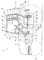
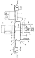
図1に示す如く、本実施の形態に係るトラクタは、エンジン2と、フライホイールハウジング、クラッチハウジング、ミッションケース等からなる伝動ケース3とを連結してなる車体1を有し、該車体1の前部は左右一対の前輪6によって支持され、後部は左右一対の後輪7によって支持されている。該車体1の前部には、ラジエータやバッテリー等の車両機器が配備され、これら車両機器は開閉自在のボンネット8によって覆われている。また、車体1の後部にはキャビン9が搭載されている。
Hereinafter, embodiments of the present invention will be described with reference to the drawings.
As shown in FIG. 1, the tractor according to the present embodiment includes a vehicle body 1 formed by connecting an engine 2 and a transmission case 3 including a flywheel housing, a clutch housing, a transmission case, and the like. The front part is supported by a pair of left and right front wheels 6, and the rear part is supported by a pair of left and right rear wheels 7. Vehicle devices such as a radiator and a battery are provided at the front portion of the vehicle body 1, and these vehicle devices are covered with an openable / closable bonnet 8. A cabin 9 is mounted on the rear portion of the vehicle body 1.

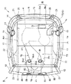
図1及び図2に示す如く、キャビン9は、骨格となるキャビンフレーム11を有し、該
キャビンフレーム11は、前部に配備された左右一対のフロントピラー12と、後部に配備された左右一対のリアピラー13と、左右一対のフロントピラー12の上端を連結するフロントルーフビーム15と、左右一対のリアピラー13の上端を連結するリアルーフビーム16と、左右方向で同じ側にあるフロントピラー12とリアピラー13の上端を連結する左右一対のサイドルーフビーム17と、左右一対のリアピラー13の下端を連結するリアミドルビーム18と、左右各リアピラー13の下端側から前下方に向けてキャビン9底部にまで延びる左右一対のサイドフレーム19とを備えている。
As shown in FIGS. 1 and 2, the cabin 9 has a cabin frame 11 as a skeleton, and the cabin frame 11 includes a pair of left and right front pillars 12 disposed at the front and a pair of left and right front pillars disposed at the rear. The rear pillar 13, the front roof beam 15 that connects the upper ends of the pair of left and right front pillars 12, the rear roof beam 16 that connects the upper ends of the pair of left and right rear pillars 13, and the front pillar 12 and the rear pillar on the same side in the left and right direction. A pair of left and right side roof beams 17 connecting the upper ends of the pair 13, a rear beam 18 connecting the lower ends of the pair of left and right rear pillars 13, and extending from the lower ends of the left and right rear pillars 13 to the bottom of the cabin 9 toward the front and lower side. A pair of left and right side frames 19 is provided.

該左右一対のサイドフレーム19は、後輪7に略沿うように前上方に向けて凸湾曲状の湾曲部と、該湾曲部の先端からフロントピラー12の下端側に延びる横架部とから構成されている。
キャビン9の上部側背面には、リアルーフビーム16とリアミドルビーム18とを連結する左右一対の上背面ピラー20が配置され、キャビン9の下部側背面には、リアミドルビーム18からキャビン9の底部に向けて延びる左右一対の下背面ピラー21が配備されている。
The pair of left and right side frames 19 includes a curved portion that is convexly curved toward the front upper side so as to substantially follow the rear wheel 7, and a horizontal portion that extends from the tip of the curved portion to the lower end side of the front pillar 12. Has been.
A pair of left and right upper and rear pillars 20 that connect the rear roof beam 16 and the reamidel beam 18 are disposed on the upper rear surface of the cabin 9, and on the lower rear surface of the cabin 9, A pair of left and right lower back pillars 21 extending toward the bottom are provided.

該左右一対の下背面ピラー21の下端部にはそれぞれ、車体1の前後方向に沿って延びるサイドフロアビーム22が配置されている。
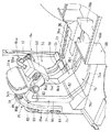
また、図2及び図3に示す如く、左右一対のフロントピアー12の下端部には、対向するフロントピアー12に向けて延びるフロントフロアビーム23が連結されており、前記左右一対のサイドフロアビーム22の先端部は、フロントピアー12の下端部から左右方向で同じ側にあるフロントフロアビーム23の左右方向中途部に連結されている。
また、左右一対のフロントピアー12の間には、キャビン9の室内と室外を仕切る板状のフロントパネル24が該左右一対のフロントピアー12の間の左右方向中央部且つ上下方向やや下方に配備されており、該フロントパネル24の側下端部はそれぞれ、左右方向で同じ側となるフロントフロアビーム23に連結されている。
Side floor beams 22 extending along the front-rear direction of the vehicle body 1 are disposed at the lower ends of the pair of left and right lower back pillars 21.
Further, as shown in FIGS. 2 and 3, a front floor beam 23 extending toward the opposed front peer 12 is connected to the lower ends of the pair of left and right front peers 12. Is connected to a midway portion in the left-right direction of the front floor beam 23 on the same side in the left-right direction from the lower end portion of the front pier 12.
Between the pair of left and right front peers 12, a plate-like front panel 24 that partitions the cabin 9 from the outside is disposed in the middle in the left and right direction between the pair of left and right front peers 12 and slightly below in the vertical direction. The lower end of the front panel 24 is connected to the front floor beam 23 that is on the same side in the left-right direction.

図1に示す如く、左右各サイドフロアビーム22の前端側は、伝動ケース3の前部の側部に設けられたブラケット26にマウントゴム(防振ゴム)を介して取付支持され、左右下背面ピラー21の下部に固定されたブラケット28は、後車軸を支持する後車軸ケースに取付固定された支持台29にマウントゴムを介して取付支持されており、これによってキャビン9が車体1に支持されている。
また、左右一対のフロントピラー12間にはフロントウインド31が設けられ、左右方向で同じ側にあるフロントピラー12とリアピラー13との間は乗降口とされ、該フロントピラー12とリアピラー13との間にはドア32が設けられている。
As shown in FIG. 1, the front end sides of the left and right side floor beams 22 are mounted and supported by brackets 26 provided on the front side portions of the transmission case 3 via mount rubber (anti-vibration rubber). The bracket 28 fixed to the lower portion of the pillar 21 is mounted and supported via a mount rubber on a support base 29 mounted and fixed to a rear axle case that supports the rear axle, whereby the cabin 9 is supported by the vehicle body 1. ing.
Further, a front window 31 is provided between the pair of left and right front pillars 12, and the front and rear pillars 12 and 13 located on the same side in the left and right direction serve as entrances and exits between the front pillar 12 and the rear pillar 13. Is provided with a door 32.

また、左右方向で同じ側にあるリアピラー13と上背面ピラー20との間にはリアサイドウインド33が設けられ、左右の上背面ピラー20間にはリアウインドが設けられている。
また、図2及び図3に示す如く、キャビンフレーム11の側部後下部には、左右方向で同じ側にあるサイドフレーム19の湾曲部からサイドフロアビーム22までを塞ぐ板状のサイドパネル35が左右にそれぞれ配備され、これら左右一対のサイドパネル35の間には、キャビンフレーム11を底部から背面下部にかけて塞ぐ板状のフロアシート36が設けられている。
Further, a rear side window 33 is provided between the rear pillar 13 and the upper back pillar 20 on the same side in the left-right direction, and a rear window is provided between the left and right upper back pillars 20.
Further, as shown in FIGS. 2 and 3, a plate-like side panel 35 that closes from the curved portion of the side frame 19 to the side floor beam 22 on the same side in the left-right direction is provided at the rear rear portion of the side portion of the cabin frame 11. A plate-like floor sheet 36 is provided between the pair of left and right side panels 35 so as to close the cabin frame 11 from the bottom portion to the lower back portion.

図1及び図2に示す如く、フロアシート36は、キャビン9の底部を構成する底壁部36aと、該底壁部36aの後端縁から後方に向かうに従って上方に移行する傾斜方向に延出された背面壁36bとを備えている。
また、サイドパネル35の左右方向外面側には、後輪7を前方から上方にかけて覆う後輪フェンダ(図示省略)がそれぞれ設けられている。
また、図3に示す如く、キャビンフレーム11の上部にはルーフ39が設けられ、該ルーフ39は中空状に形成されており、該ルーフ39の左右一側、本実施の形態では左側部の後部には、外側方に突出した外気取入れ部42が設けられている。
As shown in FIGS. 1 and 2, the floor sheet 36 extends in an inclined direction in which the floor wall 36a that forms the bottom of the cabin 9 and an upward transition from the rear edge of the bottom wall 36a toward the rear. And a rear wall 36b.
Further, rear wheel fenders (not shown) that cover the rear wheel 7 from the front to the top are provided on the outer side of the side panel 35 in the left-right direction.
Further, as shown in FIG. 3, a roof 39 is provided at the upper part of the cabin frame 11, and the roof 39 is formed in a hollow shape. Is provided with an outside air intake 42 projecting outward.

該外気取入れ部42は、キャビン9の外部の空気(外気)をルーフ39の下面に設けられた外気取入れ口43からフィルタを通してルーフ39内の中空状の空間に取り入れるように構成されている。
また、図2に示す如く、左右一対のリアピラー13は中空状に形成されており、左側のリアピラー13の上部開口はルーフ39の前記中空状の空間に連通されている。これによって外気取入れ部42からルーフ39内に取り入れられた外気が該リアピラー13内を通過することが可能となっている。
The outside air intake portion 42 is configured to take air outside the cabin 9 (outside air) from an outside air intake port 43 provided on the lower surface of the roof 39 through a filter into a hollow space in the roof 39.
As shown in FIG. 2, the pair of left and right rear pillars 13 are formed in a hollow shape, and the upper opening of the left rear pillar 13 communicates with the hollow space of the roof 39. As a result, the outside air taken into the roof 39 from the outside air intake 42 can pass through the rear pillar 13.

前記キャビンフレーム11、フロントパネル24、フロントウインド31、ドア32、リアサイドウインド33、リアウインド34、サイドパネル35、フロアシート36、ルーフ39等でキャビン室が形成されている。
図1に示す如く、キャビン9の内部には、後部にオペレータが着座すべき着座部51が配備されると共に、前部に車体1を操作するための操作部52が配備されている。
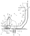
図4、図5及び図8に示す如く、前記操作部52は、前記フロントパネル24の前後面に亘って配備されたステアリング機構53、フロントパネル24の上後方に配備された計器部54a、ワイパモータ54b、フロントパネル24の後方に配備されたクラッチペダル55及び左右一対のブレーキペダル56等を備えている。
A cabin chamber is formed by the cabin frame 11, the front panel 24, the front window 31, the door 32, the rear side window 33, the rear window 34, the side panel 35, the floor seat 36, the roof 39, and the like.
As shown in FIG. 1, a seating portion 51 on which an operator should be seated is provided in the cabin 9, and an operation portion 52 for operating the vehicle body 1 is provided in the front portion.
As shown in FIGS. 4, 5, and 8, the operation unit 52 includes a steering mechanism 53 disposed across the front and rear surfaces of the front panel 24, an instrument unit 54 a disposed on the upper and rear sides of the front panel 24, and a wiper motor. 54b, a clutch pedal 55 disposed on the rear side of the front panel 24, a pair of left and right brake pedals 56, and the like.

図1及び図6に示す如く、ステアリング機構53は、キャビン9の外方からフロントパネル24に取り付けられたパワステコントローラ57と、キャビン9の内部に配備されたステアリングハンドル59と、パワステコントローラ57とステアリングハンドル59とを連結すべくキャビン9の内外に架け渡された伝動軸60とを備え、ステアリングハンドル59のハンドル軸59aはハンドルポスト58に軸方向に回転自在に内嵌されている。また、該ハンドル軸59aと伝動軸60とは、フロントパネル24の後方にて自在継手61を介して連結されている。また、ハンドルポスト58及び自在継手61のハンドル軸側は、ハンドルカバー63によって覆われている。   As shown in FIGS. 1 and 6, the steering mechanism 53 includes a power steering controller 57 attached to the front panel 24 from the outside of the cabin 9, a steering handle 59 disposed inside the cabin 9, the power steering controller 57, and the steering. A transmission shaft 60 is provided between the inside and outside of the cabin 9 so as to connect the handle 59. A handle shaft 59a of the steering handle 59 is fitted into the handle post 58 so as to be rotatable in the axial direction. Further, the handle shaft 59a and the transmission shaft 60 are connected via a universal joint 61 at the rear of the front panel 24. The handle post 58 and the handle shaft side of the universal joint 61 are covered with a handle cover 63.

また、図8に示す如く、クラッチパネル55及び左右一対のブレーキペダル56は、フロントパネル24の後方に配備された横軸体62に揺動可能に枢支されている。
また、図1に示す如く、前記着座部51は、オペレータが着座するシート64と、該シート64を支持するクッション装置及び前後位置調整装置等を備えたシート支持部65と、該シート支持部65を支持するシート台66とを備えている。
該シート台66は、フロアシート36と上下方向に間隔をおいて位置する上部壁66aと、この上部壁66aの前縁から下方に且つフロアシート36にまで延出する前部壁66
bとを備えている。また、該シート台66は、左右両側縁が前記サイドパネル35に溶接等によって固着され、上部壁66aの後縁がフロアシート36の背面壁36bに溶接等によって固着され、前部壁66bの下縁が溶接等によってフロアシート36に固着されている。
In addition, as shown in FIG. 8, the clutch panel 55 and the pair of left and right brake pedals 56 are pivotally supported by a horizontal shaft body 62 disposed behind the front panel 24.
As shown in FIG. 1, the seat 51 includes a seat 64 on which an operator is seated, a seat support 65 including a cushion device and a front / rear position adjustment device for supporting the seat 64, and the seat support 65. And a seat base 66 for supporting the above.
The seat base 66 includes an upper wall 66a that is vertically spaced from the floor sheet 36, and a front wall 66 that extends downward from the front edge of the upper wall 66a to the floor seat 36.
b. Moreover, the sheet base 66, left and right side edges are fixed by welding or the like to the side panel 35, the rear edge of the top wall 66a is fixed by welding or the like to the rear wall 36b of the floor sheet 36, under the front wall 66b The edge is fixed to the floor sheet 36 by welding or the like.

また、キャビン9には、該キャビン9の内部を空調するためのエアダクト構造70が形成されており、該エアダクト構造70は、外気を導入するための外気導入ダクト部71と、該外気導入ダクト部71から取り入れた外気とキャビン室内の空気(内気)とを取り込んで空調を図るエアコン本体Aを収容したエアコン収容部72と、該エアコン収容部72に連通されてエアコン本体Aからの空調空気をキャビン9内に導出する空調空気導出ダクト部73とを有している。
エアコン本体Aは、冷房装置と暖房装置とを備えている。
The cabin 9 is formed with an air duct structure 70 for air conditioning the interior of the cabin 9. The air duct structure 70 includes an outside air introduction duct portion 71 for introducing outside air, and the outside air introduction duct portion. An air conditioner accommodating portion 72 that accommodates an air conditioner main body A that takes in outside air taken in from 71 and air in the cabin (internal air) and performs air conditioning, and is connected to the air conditioner accommodating portion 72 to supply conditioned air from the air conditioner main body A to the cabin. 9 has an air-conditioning air lead-out duct portion 73 leading into the inside.
The air conditioner main body A includes a cooling device and a heating device.

冷房装置は、例えば、冷媒を圧縮するコンプレッサーと、該コンプレッサーで圧縮された冷媒を放熱させながら凝縮・液化させるコンデンサー(放熱器)と、該コンデンサーで液化された冷媒を減圧して気化しやすい状態とする膨張弁と、冷媒を気化させて周囲から熱を奪って周囲を低温状態とするエバポレータ(蒸発器)とを備えている。
暖房装置は、例えば、エンジン2の熱で熱せられた温媒をヒータに送ると共に該ヒータからエンジン2側に戻すように温媒を循環させるようにした構造のものが採用される。
該エアコン本体Aは、ケーシング内にエバポレータとヒータと送風機(ブロワ)等とを収納してなると共にキャビン9室内に配置されており、コンプレッサーと、放熱器と、膨張弁等はボンネット8内に配置されている。
The cooling device includes, for example, a compressor that compresses the refrigerant, a condenser (heat radiator) that condenses and liquefies the refrigerant compressed by the compressor, and a state in which the refrigerant liquefied by the condenser is decompressed and easily vaporized. And an evaporator (evaporator) that evaporates the refrigerant and removes heat from the surroundings to bring the surroundings into a low-temperature state.
As the heating device, for example, a structure in which the heating medium heated by the heat of the engine 2 is sent to the heater and the heating medium is circulated so as to return from the heater to the engine 2 side is employed.
The air conditioner main body A is provided with an evaporator, a heater, a blower, and the like housed in a casing and disposed in the cabin 9, and a compressor, a radiator, an expansion valve, and the like are disposed in the hood 8. Has been.

なお、エアコン本体Aは、最低限、冷房装置のエバポレータと送風機とを備えていればよい。
図2及び図3に示す如く、外気導入ダクト部71は、上述の如くルーフ39に形成された外気取り入れ部42と、前記ルーフ39内の中空状の空間を通じて外気取り入れ部42に連通された左側のリアピラー13とを備え、エアコン収容部72は、前記フロアシート36と左右のサイドパネル35とシート台66とによって密閉状に形成されており、該エアコン収容部72と外気導入ダクト部71とは、左側のサイドパネル35の内面側に配備された中継ダクト74を介して互いに連通されている。
In addition, the air conditioner main body A should just be equipped with the evaporator and air blower of a cooling device at the minimum.
As shown in FIGS. 2 and 3, the outside air introduction duct portion 71 has an outside air intake portion 42 formed in the roof 39 as described above, and a left side communicated with the outside air intake portion 42 through a hollow space in the roof 39. The rear pillar 13 is provided, and the air conditioner accommodating portion 72 is formed in a sealed shape by the floor seat 36, the left and right side panels 35, and the seat base 66. The air conditioner accommodating portion 72 and the outside air introduction duct portion 71 are The left side panel 35 communicates with each other via a relay duct 74 disposed on the inner surface side.

エアコン収容部72は、上述の如くフロアシート36、シート台66の上部壁66a及び前部壁66bによって形成された密閉状の空間Sによって形成されており、該空間Sにエアコン本体Aが収容されている。
また、エアコン収容部72を構成する壁部、本実施の形態ではシート台66の上部壁66aの左側の後部側には、フィルタを介してキャビン9室内の空気(内気)をエアコン収容部72内に取り入れる内気取入れ部75が設けられている。
また、エアコン本体Aの前面側右側には、該エアコン本体Aから空調空気を送出する送出口A1が設けられ、該送出口A1にはエアコン本体Aから送出された空調空気を導出する前記空調空気導出ダクト部73が接続されている。
The air conditioner accommodating portion 72 is formed by the sealed space S formed by the floor sheet 36 and the upper wall 66a and the front wall 66b of the seat base 66 as described above, and the air conditioner main body A is accommodated in the space S. ing.
Further, in the wall portion constituting the air conditioner accommodating portion 72, in this embodiment, on the rear side on the left side of the upper wall 66a of the seat base 66, the air (inside air) in the cabin 9 is passed through the filter into the air conditioner accommodating portion 72. An inside air intake part 75 is provided.
Further, on the right side of the front surface side of the air conditioner main body A, an outlet A1 for sending conditioned air from the air conditioner main body A is provided, and the conditioned air for deriving the conditioned air sent from the air conditioner main body A to the outlet A1 A lead-out duct portion 73 is connected.

図4及び図5に示す如く、空調空気導出ダクト部73は、フロアシート36に沿ってキャビン9の底部を前後方向に延びる送出しダクト76と、該送出しダクト76に連通され
てキャビン9の前部を上下方向に延びる送風ダクト77と、該送風ダクト77に連通されてエアコン本体Aからの空調空気をキャビン9内に吹き出す吹出しダクト78とから形成されている。
送出しダクト76は、合成樹脂によって形成され、フロアシート36の底壁部31a(キャビン9の底部)に沿って前方に延出した延出部76aと、該延出部76aの後端から後上方に斜行する後斜行部76bと、フロアシート36の底壁部36aの左右方向中央部の形状に沿って前上方に斜行する前斜行部76cとから構成されている。
As shown in FIGS. 4 and 5, the conditioned air lead-out duct portion 73 is connected to the feed duct 76 extending in the front-rear direction along the floor sheet 36 along the bottom portion of the cabin 9, and communicated with the feed duct 76. A blower duct 77 extending in the vertical direction on the front part and a blowout duct 78 that communicates with the blower duct 77 and blows conditioned air from the air conditioner main body A into the cabin 9 are formed.
The delivery duct 76 is formed of synthetic resin, and extends forward along the bottom wall portion 31a of the floor sheet 36 (the bottom portion of the cabin 9), and the rear from the rear end of the extension portion 76a. A rear oblique portion 76b that obliquely moves upward, and a front oblique portion 76c that obliquely moves forward and upward along the shape of the center portion in the left-right direction of the bottom wall portion 36a of the floor sheet 36.

また、フロアシート36の底壁部36a前部の左右方向中央側には、フロアシート36を上方から下方に向けて凹ませることにより形成された収容部36cが形成され、前記送出しダクト76の延出部76aは、該収容部36cに収容されるように下方に向けて凸状に屈曲形成されており、該延出部76aの上面は、収容部36cの上端縁よりも下方に位置している。
また、前記空間Sを形成するフロアシート36の底壁部36aの後部側にも、フロアシート36を上方から下方に向けて凹ませることにより形成された凹部36dが形成され、該凹部36d上にエアコン本体Aを収容することにより、送出しダクト76の後斜行部76bがキャビン9室内に露出しないように構成されている。
A receiving portion 36c formed by denting the floor sheet 36 downward from above is formed on the center side in the left-right direction of the front portion of the bottom wall portion 36a of the floor sheet 36. The extension portion 76a is formed to be bent downward so as to be accommodated in the accommodation portion 36c, and the upper surface of the extension portion 76a is located below the upper end edge of the accommodation portion 36c. ing.
Further, a recess 36d is formed on the rear side of the bottom wall portion 36a of the floor sheet 36 that forms the space S. The recess 36d is formed by denting the floor sheet 36 downward from above, and the recess 36d is formed on the recess 36d. By accommodating the air conditioner main body A, the rear oblique portion 76b of the delivery duct 76 is configured not to be exposed in the cabin 9 room.

また、フロアシート36の底壁部36aの上部には、ゴム等からなるフロアマット(図示省略)を敷設可能であり、上述の如く送出しダクト76の延出部76aの上面がフロアシート36の収容部36cの上端縁よりも下方に位置することにより、フロアマットは可及的に平坦に敷設され、これによって、オペレータが移動することとなる足元が凸状に盛り上がることはない。
前記送風ダクト77は、前記フロントパネル24に形成されたダクト形成部79と、該ダクト形成部79をキャビン室内側より覆うダクト構成部材80とから形成されている。
Further, a floor mat (not shown) made of rubber or the like can be laid on the upper portion of the bottom wall portion 36a of the floor sheet 36, and the upper surface of the extending portion 76a of the delivery duct 76 is the floor sheet 36 as described above. By being positioned below the upper edge of the accommodating portion 36c, the floor mat is laid as flat as possible, so that the feet that the operator will move will not rise in a convex shape.
The air duct 77 is formed of a duct forming portion 79 formed on the front panel 24 and a duct constituting member 80 that covers the duct forming portion 79 from the cabin interior side.

図7に示す如く、ダクト形成部79は、フロントパネル24を構成する平板をプレス成型することによって形成され、フロントパネル24の上下方向に延びる左右一対の屈曲部79aと、該左右一対の屈曲部79aの間に形成された平坦部79bとを備え、キャビン9の前側に膨出している。また、左右一対の屈曲部79aは、図8に示す如く、前記ダクト構成部材80の上端部よりもフロントパネル24の上端側にて左右方向に延びる屈曲凹部79cを介して互いに連結されている。
図7に示す如く、ダクト構成部材80は、合成樹脂によって形成され、ダクト形成部79に対向して上下方向に延びる平坦部80aと、該平坦部80aの左右両側からダクト形成部79に向けて延びる左右一対の脚部80bとを備えた断面コ字状に形成されており、各脚部80bは、ダクト形成部79の左右方向で同じ側となる屈曲部79aの外側に当接した状態でフロントパネル24の上下方向に沿って延びている。
As shown in FIG. 7, the duct forming portion 79 is formed by press-molding a flat plate constituting the front panel 24, and a pair of left and right bent portions 79a extending in the vertical direction of the front panel 24, and the pair of left and right bent portions. 79a and a flat portion 79b formed between 79a and bulges to the front side of the cabin 9. Further, as shown in FIG. 8, the pair of left and right bent portions 79 a are connected to each other via a bent recess 79 c that extends in the left-right direction on the upper end side of the front panel 24 relative to the upper end portion of the duct component member 80.
As shown in FIG. 7, the duct component member 80 is formed of a synthetic resin and extends in a vertical direction facing the duct forming portion 79, and from the left and right sides of the flat portion 80 a toward the duct forming portion 79. The leg portions 80b are formed in a U-shaped cross section including a pair of left and right leg portions 80b, and the leg portions 80b are in contact with the outside of the bent portion 79a on the same side in the left-right direction of the duct forming portion 79. It extends along the vertical direction of the front panel 24.

また、図4及び図5に示す如く、ダクト構成部材80の下端部は、フロントパネル24の屈曲形状に沿って後下方に向けて屈曲しており、前記送出しダクト76の先端部と対向している。そして、これらダクト構成部材80の下端部と送出しダクト76の先端部が帯状のダクト連結部材82を介して連結されることにより、送風ダクト77と送出しダクト76とが互いに連通されている。
また、ダクト構成部材80は、図7に示す如く、平坦部80aに立設された複数の板状の支持体81を介して前記横軸体62を支持している。
4 and 5, the lower end portion of the duct component member 80 is bent rearward and downward along the bent shape of the front panel 24, and is opposed to the front end portion of the delivery duct 76. ing. Then, the lower end portion of the duct constituent member 80 and the tip end portion of the delivery duct 76 are connected via a belt-like duct connection member 82, whereby the air duct 77 and the delivery duct 76 are communicated with each other.
Further, as shown in FIG. 7, the duct component member 80 supports the horizontal shaft body 62 via a plurality of plate-like support bodies 81 erected on the flat portion 80 a.

さらに、図6に示す如く、送風ダクト77にはキャビン9の室内外を貫通する筒体77aが配備され、該筒体77aに前記伝動軸60がブッシュ等を介して軸心廻りに回転自在に挿通されている。
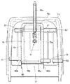
図5及び図6に示す如く、前記吹出しダクト78は、合成樹脂によって形成され、前記エアコン本体Aからの空調空気が送り込まれる吹出し基部83と、該吹出し基部83に連結されてキャビン9内を空調すべく空調空気を吹き出すメインダクト部84と、前記吹出し基部83に連結されて前記空調空気をフロントウインド31に吹き出すデフロスタダクト部85とを備え、前記吹出し基部83には、前記空調空気をメインダクト部84とデフロスタダクト部85に分配する空気分配機構86が配備されている。
Further, as shown in FIG. 6, the air duct 77 is provided with a cylindrical body 77a penetrating the cabin 9 inside and outside, and the transmission shaft 60 is rotatable around the shaft center through a bush or the like in the cylindrical body 77a. It is inserted.
As shown in FIGS. 5 and 6, the blowout duct 78 is formed of a synthetic resin, and is connected to the blowout base 83 to which the conditioned air from the air conditioner main body A is sent, and is connected to the blowout base 83 to air-condition the cabin 9. a main duct 84 for blowing conditioned air in order to, the balloon and a defroster duct 85 for blowing the conditioned air is connected to the base 83 in the front window 31, wherein the blowing base 83, the main duct the conditioned air An air distribution mechanism 86 that distributes the air to the portion 84 and the defroster duct portion 85 is provided.

前記吹出し基部83は、フロントパネル24の上端側に位置して送風ダクト77の上端と対向しており、これら吹出し基部83の下端部と送風ダクト77の上端部とは帯状のダクト連結部材82を介して連結されている。これによって、吹出しダクト78と送風ダクト77とは互いに連通されている。
メインダクト部84は、メイン連通孔87を介して吹出し基部83に連通されており、図4に示す如く、前記ステアリングハンドル59のハンドル軸59aを跨いだ状態でキャビン9の後方に向けて延伸される左右一対のメイン吹出し部84aを備えたマニホールド状に形成され、該メイン吹出し部84aの先端部には、キャビン9の上方に向けて空調空気を吹き出すアッパー吹出し口84bと、キャビン9の下方に向けて空調空気を吹き出すロア吹出し口84cとが形成されている。
The outlet base 83 is located on the upper end side of the front panel 24 and faces the upper end of the air duct 77. The lower end of the outlet base 83 and the upper end of the air duct 77 form a strip-shaped duct connecting member 82. Are connected through. As a result, the blowout duct 78 and the blower duct 77 communicate with each other.
The main duct portion 84 communicates with the blowout base portion 83 through the main communication hole 87 and extends toward the rear of the cabin 9 while straddling the handle shaft 59a of the steering handle 59 as shown in FIG. The upper and lower outlets 84b for blowing conditioned air toward the upper side of the cabin 9 and the lower side of the cabin 9 are formed in a manifold shape having a pair of left and right main outlets 84a. A lower outlet 84c that blows out the conditioned air is formed.

また、メイン吹出し部84aの前後方向中途部には、キャビン9の後方に向かうに連れて左右方向外方に移行する方向を向くサイド吹出し口84dが設けられている。
なお、前記各吹出し口84b、84c、84dには、風向きを変更する風向き変更グリルが配備されている。
デフロスタダクト部85は、フロントパネル24の外縁部に沿って上下方向に延びる左右一対の側部分85aと、該左右側部分85aの上端を連結する上部分85bとによって、フロントパネル24の外縁に沿う門型状に形成されている。
In addition, a side outlet 84d is provided at a midway part in the front-rear direction of the main outlet part 84a so as to face the direction of moving outward in the left-right direction as it goes rearward of the cabin 9.
A wind direction changing grill for changing the wind direction is provided at each of the outlets 84b, 84c, 84d.
The defroster duct portion 85 extends along the outer edge of the front panel 24 by a pair of left and right side portions 85a extending in the vertical direction along the outer edge portion of the front panel 24 and an upper portion 85b connecting the upper ends of the left and right side portions 85a. It is formed in a gate shape.

また、図5に示す如く、上部分85bは、前記ワイパモータ54bとフロントウインド31の間に配備されており、デフ挿通孔88を介して吹出し基部83に連結されている。
図3に示す如く、前記左右一対の側部分82a及び上部分82bには、複数箇所にフロントウインド31の内面側に向けて空気を吹き出す複数(本実施の形態においては6つ)のデフ吹出し口89がフロントウインド31に対して放射状に配備されている。
該デフ吹出し口89の幅は、図5及び図7に示す如く、前記側部分82a及び上部分82bの幅よりも小さく形成されている。この様に側部分82a及び上部分82b内を流れるメインの空調空気の流れに対してデフ吹出し口89の開口幅に段差を設けることにより、フロントウインド31の内面側に向けて吹き出される空調空気の流速が側部分82a及び上部分82b内での流速よりも速いものとなって、これによって該空調空気によるフロントウインド31の曇り止め効果がより向上される。
Further, as shown in FIG. 5, the upper portion 85 b is disposed between the wiper motor 54 b and the front window 31, and is connected to the blowing base 83 through the differential insertion hole 88.
As shown in FIG. 3, a plurality of (six in this embodiment) differential outlets for blowing air toward the inner surface side of the front window 31 at a plurality of locations on the pair of left and right side portions 82a and upper portion 82b. 89 are arranged radially with respect to the front window 31.
The width of the differential outlet 89 is smaller than the width of the side portion 82a and the upper portion 82b, as shown in FIGS. In this way, by providing a step in the opening width of the differential outlet 89 with respect to the flow of the main conditioned air flowing in the side portion 82a and the upper portion 82b, the conditioned air blown toward the inner surface side of the front window 31. Is faster than the flow velocity in the side portion 82a and the upper portion 82b, and this further improves the anti-fogging effect of the front window 31 by the conditioned air.

また、図7に示す如く、フロントパネル24は、デフロスタダクト部85と対向する外縁部がプレス成型されている。
また、図5に示す如く、前記メイン挿通孔87とデフ挿通孔88は、吹出し基部83内にて互いに対向しており、これらメイン挿通孔87とデフ挿通孔88との間に前記空気分配機構86が配備されている。
空気分配機構86は、メイン連通孔87とデフ連通孔88とを択一的に閉塞可能な蓋体90を備え、該蓋体90は、平板状に形成されて上端がヒンジ機構91を介して枢支されており、メイン連通孔87を閉塞する第1閉塞位置とデフ連通孔88を閉塞する第2閉塞位置との間で揺動自在に支持されている。
Further, as shown in FIG. 7, the outer edge portion of the front panel 24 facing the defroster duct portion 85 is press-molded.
Further, as shown in FIG. 5, the main insertion hole 87 and the differential insertion hole 88 face each other in the blowout base 83, and the air distribution mechanism is interposed between the main insertion hole 87 and the differential insertion hole 88. 86 is deployed.
The air distribution mechanism 86 includes a lid body 90 that can alternatively close the main communication hole 87 and the differential communication hole 88, and the lid body 90 is formed in a flat plate shape with an upper end interposed via a hinge mechanism 91. It is pivotally supported and is swingably supported between a first closing position for closing the main communication hole 87 and a second closing position for closing the differential communication hole 88.

また、蓋体90は、吹出し基部83からメインダクト部84に流れる空調空気と、吹出し基部83からデフロスタダクト部85に流れる空調空気との割合を変更可能とすべく、前記第1閉塞位置と第2閉塞位置の間の任意の位置で駐止可能に構成されている。
また、送風ダクト77の上部及び吹出しダクト78は、前記ステアリング機構53のハンドルポスト58の基部、横軸体62、支持体81等と共にインストルメントパネル(図示省略)によって覆われており、吹出しダクト78の各吹出し口84b、84c、84dは、該インストルメントパネルに適宜形成された開口を介してキャビン9の内部に通じている。
Further, the lid 90 has the first closed position and the first closed position so that the ratio of the conditioned air flowing from the blowing base 83 to the main duct portion 84 and the conditioned air flowing from the blowing base 83 to the defroster duct portion 85 can be changed. It is configured to be able to park at any position between the two closed positions.
The upper part of the blower duct 77 and the blowout duct 78 are covered by an instrument panel (not shown) together with the base of the handle post 58 of the steering mechanism 53, the horizontal shaft body 62, the support 81 and the like. Each of the outlets 84b, 84c, 84d communicates with the interior of the cabin 9 through an opening appropriately formed in the instrument panel.

本実施の形態は以上の構成からなるものであって、図3に示す外気取入れ口43を開放することにより、外気がエアダクト構造70の外気導入ダクト部71を通じてエアコン収容部72に導入される。このとき、図2に示す前記内気取り入れ部75を開放することにより、キャビン9内の空気をエアコン収容部72に導入することも可能である。
そして、これら外気及び内気は、エアコン収容部72のエアコン本体Aによって温度・湿度等が調整されると共に塵芥等が除去された空調空気となり、該空調空気は図5に示す空調空気導出ダクト部73によってキャビン9の後下部からキャビン9の前部に案内される。このとき、送出しダクト76の延出部76a、後斜行部76b、前斜行部76c及び送風ダクト77がフロアシート36に沿って配備されることにより、空調空気導出ダクト部73はキャビン9の外方に向けて凸の円弧状に形成されることとなり、これによって、該空調空気導出ダクト部73を流れる空調空気の送風ロスが可及的に減じられる。
The present embodiment has the above-described configuration, and the outside air is introduced into the air conditioner housing portion 72 through the outside air introduction duct portion 71 of the air duct structure 70 by opening the outside air intake port 43 shown in FIG. At this time, it is also possible to introduce the air in the cabin 9 into the air conditioner accommodating portion 72 by opening the inside air intake portion 75 shown in FIG.
The outside air and the inside air are conditioned air in which the temperature and humidity are adjusted by the air conditioner main body A of the air conditioner accommodating portion 72 and dust and the like are removed, and the conditioned air is the conditioned air deriving duct portion 73 shown in FIG. Is guided from the rear lower part of the cabin 9 to the front part of the cabin 9. At this time, the extended portion 76a, the rear oblique portion 76b, the front oblique portion 76c, and the air duct 77 of the delivery duct 76 are arranged along the floor sheet 36, so that the conditioned air outlet duct portion 73 is connected to the cabin 9. Thus, the air loss of the conditioned air flowing through the conditioned air outlet duct portion 73 is reduced as much as possible.

そして、送出しダクト76によってキャビン9の前部に流れ込んだ空調空気は、キャビン9の前部を上下方向に延びる送風ダクト77を通過し、該送風ダクト77の上部に配備された吹出しダクト78に流れ込む。
吹出しダクト78に至った空調空気は、先ず、吹出し基部83に流れ込む。そして、吹出し基部83内に配備された空気分配機構86によって、メインダクト部84とデフロスタダクト部85に分配される。
空気分配機構86の蓋体90が前記第1閉塞位置に設定された場合、吹出し基部83とメインダクト部84とを連通するメイン連通孔87が蓋体90によって閉塞されるため、メインダクト部84に空調空気が流れ込むことはなく、空調空気はすべてデフ連通孔88を通じてデフロスタダクト部85に流れ込むこととなる。
The conditioned air that has flowed into the front portion of the cabin 9 by the delivery duct 76 passes through the air duct 77 extending in the vertical direction through the front portion of the cabin 9, and enters the air outlet duct 78 disposed at the upper portion of the air duct 77. Flows in.
The conditioned air that reaches the blowout duct 78 first flows into the blowout base 83. And it distributes to the main duct part 84 and the defroster duct part 85 by the air distribution mechanism 86 arranged in the blowing base 83.
When the lid 90 of the air distribution mechanism 86 is set to the first closed position, the main communication hole 87 that connects the blowout base 83 and the main duct 84 is blocked by the lid 90, so that the main duct 84 The air-conditioned air does not flow into the defroster duct portion 85 through the differential communication hole 88.

一方、蓋体90が前記第2閉塞位置に設定された場合、吹出し基部83とデフロスタダクト部85とを連通するデフ連通孔88が蓋体90によって閉塞されるため、デフロスタダクト部85に空調空気が流れ込むことはなく、空調空気はすべてメイン連通孔87を通じてメインダクト部84に流れ込むこととなる。
また、蓋体90が第1閉塞位置と第2閉塞位置の位置で駐止された場合、メイン連通孔87側の蓋体90と吹出し基部83の内壁との間隔と、デフ連通孔88側の蓋体90と吹出し基部83の内壁との間隔に応じ、適宜空調空気が分配される。例えば、図6中に二点鎖線で示す如く、蓋体90がメイン連通孔87とデフ連通孔88の中間となる中間位置に駐止された場合、メインダクト部84とデフロスタダクト部85には、それぞれ吹出し基部83に流入した空調空気の半分が流れ込むこととなり、図6中に実線で示す如く蓋体90がデフ連通孔88側に大きく傾いた位置に駐止されている場合には、メインダクト部84にデフロスタダクト部85よりも多量の空調空気が流れ込むこととなる。
On the other hand, when the lid 90 is set to the second closed position, the diff communication hole 88 that communicates the blowing base portion 83 and the defroster duct portion 85 is closed by the lid 90, so that the defroster duct portion 85 has conditioned air. However, all of the conditioned air flows into the main duct portion 84 through the main communication hole 87.
Further, when the lid 90 is parked at the first closed position and the second closed position, the distance between the lid 90 on the main communication hole 87 side and the inner wall of the blowout base 83, and on the differential communication hole 88 side. The conditioned air is appropriately distributed according to the distance between the lid 90 and the inner wall of the outlet base 83. For example, as shown by a two-dot chain line in FIG. 6, when the lid 90 is parked at an intermediate position between the main communication hole 87 and the differential communication hole 88, the main duct portion 84 and the defroster duct portion 85 In this case, half of the conditioned air that has flowed into the blowout base 83 flows in. When the lid 90 is parked at a position greatly inclined toward the differential communication hole 88 as shown by the solid line in FIG. A larger amount of conditioned air flows into the duct portion 84 than the defroster duct portion 85.

そして、メインダクト部84に流れ込んだ空調空気は、図4に示す左右一対のメイン吹出し部84aのアッパー吹出し口84b、ロア吹出し口84c及びサイド吹出し口84dを通じてキャビン9内に吹き出され、これによってキャビン9の内部が空調されるのである。
ここで、アッパー吹出し口84bはキャビン9の後上方に向けて配備され、ロア吹出し口84cは前記操作部52の下方に向けて配備されているため、これらの吹出し口84b、85cから空調空気が吹き出されることにより、キャビン9内で空気が滞留することはない。
The conditioned air flowing into the main duct portion 84 is blown into the cabin 9 through the upper outlet 84b, the lower outlet 84c, and the side outlet 84d of the pair of left and right main outlets 84a shown in FIG. The inside of 9 is air-conditioned.
Here, since the upper outlet 84b is arranged toward the rear upper side of the cabin 9, and the lower outlet 84c is arranged below the operation portion 52, the conditioned air is supplied from these outlets 84b and 85c. By blowing out, air does not stay in the cabin 9.

また、サイド吹出し口84dは、左右方向で同じ側に位置するドア32やリアサイドウインド33と対向した位置に配備されているので、該サイド吹出し口84dから吹き出される空調空気は、ドア32及びリアサイドウインド33に沿ってキャビン9の後方に向けて流れ込むことにより、キャビン9の内部の空調を図ると共にこれらドア32及びリアサイドウインド33の曇り止めとしても有効に機能する。
なお、これらの吹出し口84b、84c、84dから吹き出される空調空気の吹出し方向は、前記風向き変更グリルによって適宜変更可能である。
Further, since the side outlet 84d is disposed at a position facing the door 32 and the rear side window 33 located on the same side in the left-right direction, the conditioned air blown from the side outlet 84d is supplied to the door 32 and the rear side. By flowing toward the rear of the cabin 9 along the window 33, the interior of the cabin 9 is air-conditioned, and the door 32 and the rear side window 33 function effectively.
In addition, the blowing direction of the conditioned air blown out from these blowing openings 84b, 84c, 84d can be appropriately changed by the wind direction changing grill.

また、デフロスタダクト部85に流れ込んだ空調空気は、左右一対の側部分85a及び上部分85bに形成されたデフ吹出し口89からフロントウインド31に向けて吹き出される。該デフ吹出し口89は、フロントウインド31の左右方向中央部やや下方から該フロントウインド31の上部及び側部に向けて放射状に配備されているため、該空調空気がフロントウインド31に沿って流れることにより、該フロントウインド31の曇りは効果的に除去されるのである。
この様に吹出しダクト78からキャビン9内に吹き出された空調空気は、ドア32、リアサイドウインド33に沿って後方にスムーズに流れると共にインナールーフ40内面に沿って流れてキャビン9後部の内気取入れ部75に至る。該内気取入れ部75に流れ込んだ空調空気は、エアコン収容部72を介してエアコン本体Aに吸引され、該エアコン本体Aの送出口A1から空調空気導出ダクト部73を介して再びキャビン9の前部からキャビン9内に向けて吹き出される。この様なエアダクト構造70によって、キャビン室の内気循環が効率よく行われるようになっている。
The conditioned air that has flowed into the defroster duct portion 85 is blown out toward the front window 31 from the differential outlet 89 formed in the pair of left and right side portions 85a and the upper portion 85b. The differential outlet 89 is arranged radially from a slightly lower central portion in the left-right direction of the front window 31 toward the upper and side portions of the front window 31, so that the conditioned air flows along the front window 31. Thus, the fogging of the front window 31 is effectively removed.
The conditioned air blown into the cabin 9 from the blowout duct 78 in this manner smoothly flows rearward along the door 32 and the rear side window 33 and also flows along the inner surface of the inner roof 40 to return the inside air intake 75 at the rear of the cabin 9. To. The conditioned air that has flowed into the inside air intake section 75 is sucked into the air conditioner main body A through the air conditioner housing section 72, and again from the outlet A <b> 1 of the air conditioner main body A through the conditioned air outlet duct section 73 to the front of the cabin 9 Is blown out into the cabin 9. By such an air duct structure 70, the inside air circulation of the cabin chamber is efficiently performed.

本実施の形態によれば、送風ダクト77がフロントパネル24のダクト形成部79とダクト構成部材80とによって形成されているので、フロントパネル24が送風ダクト77を構成する部材を兼ねることとなり、これによって、送風ダクト77の部品点数のが削減される。また、単板からなるフロントパネル24がダクト構成部材80によって補強されることとなり、これによってフロントパネル24の強度(剛性)が向上する。
また、フロントパネル24は、ダクト形成部79及び吹出しダクト78のデフロスタダクト部85と対向する外縁部がプレス形成されているため、これによっても強度の向上が図られている。
According to the present embodiment, since the air duct 77 is formed by the duct forming portion 79 of the front panel 24 and the duct constituent member 80, the front panel 24 also serves as a member constituting the air duct 77. Thus, the number of parts of the air duct 77 is reduced. Further, the front panel 24 made of a single plate is reinforced by the duct component member 80, thereby improving the strength (rigidity) of the front panel 24.
Further, since the outer edge portion of the front panel 24 facing the defroster duct portion 85 of the duct forming portion 79 and the blowout duct 78 is press-formed, the strength is also improved thereby.

さらに、フロントパネル24のダクト形成部79の平坦部79bの外方に前記パワステコントローラ57が配備され、ダクト構成部材80の平坦部80aに前記支持体81が配備されており、これらによってもダクト形成部79やダクト構成部材80の強度の向上が図られ、ひいては送風ダクト77を構成するフロントパネル24の強度の向上が図られているのである。
また、異なる観点からみれば、キャビン9の前部に配備されたフロントパネル24と該フロントパネル24と補強支持する部材(ダクト構成部材80)とによって送風ダクト77は形成されており、キャビン9室内の省スペース化を図りつつ、キャビン9の内部側に送風ダクト77を配備することが可能となる。これによって、送風ダクト77を通過する空調空気に対するキャビン9外部の外気やボンネット8内部の熱の影響を可及的に低減でき、エアコン本体Aの負荷を抑えることが可能となるのである。
Further, the power steering controller 57 is disposed outside the flat portion 79b of the duct forming portion 79 of the front panel 24, and the support body 81 is disposed on the flat portion 80a of the duct constituent member 80, which also forms the duct. The strength of the portion 79 and the duct constituent member 80 is improved, and as a result, the strength of the front panel 24 constituting the blower duct 77 is improved.
From a different point of view, the air duct 77 is formed by the front panel 24 disposed in the front portion of the cabin 9 and a member (duct constituent member 80) that reinforces and supports the front panel 24. The air duct 77 can be provided on the inner side of the cabin 9 while saving the space. As a result, the influence of the outside air outside the cabin 9 and the heat inside the hood 8 on the conditioned air passing through the air duct 77 can be reduced as much as possible, and the load on the air conditioner main body A can be suppressed.

また、フロントパネル24のダクト形成部79はキャビン9前方に向けて膨出しており、これによって、キャビン9内部の省スペース化を図りつつも送風ダクト77の断面積が確保されているのである。
また、キャビン9外部のフロントパネル24の前部にパワステコントローラ57が配備され、キャビン9内部のフロントパネル24の後部にステアリングハンドル59が配備され、これらパワステコントローラ57とステアリングハンドル59とを連結する伝動軸60が送風ダクト77を貫通して配備されているため、キャビン9の前部に伝動軸60及び送風ダクト77を別々に配備するための大きなスペースが必要なく、これら伝動軸60及び送風ダクト77の配置構造も簡易なものとなってキャビン9の組立が簡単となると共に製造コストも抑えられる。
Further, the duct forming portion 79 of the front panel 24 bulges toward the front of the cabin 9, thereby ensuring a cross-sectional area of the blower duct 77 while saving the space inside the cabin 9.
Further, a power steering controller 57 is provided at the front part of the front panel 24 outside the cabin 9, and a steering handle 59 is provided at the rear part of the front panel 24 inside the cabin 9, so that the power steering controller 57 and the steering handle 59 are connected. Since the shaft 60 is disposed through the air duct 77, there is no need for a large space for separately disposing the transmission shaft 60 and the air duct 77 in the front portion of the cabin 9, and the transmission shaft 60 and the air duct 77. The arrangement structure is simplified, the assembly of the cabin 9 is simplified, and the manufacturing cost is reduced.

また、本実施の形態においては、空調空気導出ダクト部73の吹出しダクト78に流れ込んだ空調空気は、吹出し基部83の空気分配機構86によってメインダクト部84に向けて流れ込むものとデフロスタダクト部85に向けて流れ込むものとに分配されることとなり、これによって、各ダクト部84、85から吹き出される空調空気の空気量をオペレータの好みに応じて調整することが可能となる。
また、空気分配機構86が吹出しダクト78に配備されていることにより、該空気分配機構86は、キャビン9室内に吹き出される直前、つまり、空調空気導出ダクト部73の最も川下となる部位に配備されていることとなる。これによって、エアダクト構造70の川上側(例えばエアコン収容部72近傍)からメインダクト部84に連通するダクトとデフロスタダクト部85に連通するダクトを分岐して形成する必要はなく、ダクト構造の簡素化が図られると共にキャビン9室内の省スペース化が図られるのである。
Further, in the present embodiment, the conditioned air that has flowed into the blowout duct 78 of the conditioned air outlet duct portion 73 flows into the main duct portion 84 by the air distribution mechanism 86 of the blowout base portion 83 and the defroster duct portion 85. Accordingly, the amount of conditioned air blown out from the duct portions 84 and 85 can be adjusted according to the preference of the operator.
In addition, since the air distribution mechanism 86 is provided in the blowout duct 78, the air distribution mechanism 86 is provided immediately before being blown into the cabin 9, that is, at the most downstream portion of the conditioned air outlet duct portion 73. Will be. Accordingly, it is not necessary to branch and form the duct communicating with the main duct portion 84 and the duct communicating with the defroster duct portion 85 from the upstream side of the air duct structure 70 (for example, in the vicinity of the air conditioner accommodating portion 72), and simplification of the duct structure. As a result, the space in the cabin 9 can be saved.

また、空気分配機構86の蓋体90を前記第1閉塞位置と第2閉塞位置との間で揺動調整する簡易な操作によって、空調空気の各ダクト部84、85への分配量は適宜調整されることとなり、これによって、状況に応じたキャビン9室内の空調状態を容易に調整することが可能となる。
また、デフロスタダクト部85は、上部分85bと側部分85aとによって門型状に形成され、該上部分85bと吹出し基部83とがデフ連通孔88を介して挿通されているため、両側部分85aの先端には吹出し基部83からの空調空気が略等しく流れ込むことと
なり、これによって、デフロスタダクト部85のデフ吹出し口89から吹き出される空調空気の空気量に左右方向の偏りが生じることはなく、フロントウインド31の曇りが略左右対称に除去されるのである。
Further, the distribution amount of the conditioned air to the duct portions 84 and 85 is appropriately adjusted by a simple operation of swinging and adjusting the lid 90 of the air distribution mechanism 86 between the first closed position and the second closed position. Thus, it becomes possible to easily adjust the air conditioning state in the cabin 9 according to the situation.
Further, the defroster duct portion 85 is formed in a gate shape by the upper portion 85b and the side portion 85a, and the upper portion 85b and the blowout base portion 83 are inserted through the differential communication holes 88. The air-conditioning air from the blowout base 83 flows into the tip of the airflow substantially equally, so that the amount of air-conditioning air blown out from the differential blowout port 89 of the defroster duct portion 85 does not cause a lateral deviation. The fogging of the front window 31 is removed substantially symmetrically.

以上、本発明の実施の形態を詳述したが、本発明は上記の実施の形態に限定されるものではない。例えば、空調空気導出ダクト部73を構成する送出しダクト76、ダクト構成部材80、吹出しダクト78は合成樹脂製とされているが、金属製とした場合にも、上記実施の形態と同様の効果が得られる。
また、フロントパネル24のダクト形成部79をキャビン9の内部に向けて膨出させた場合にも、本実施の形態と同様の効果が得られる。
また、吹出しダクト78のメインダクト部84の左右一対のメイン吹出し部84aには、アッパー吹出し口84b、ロア吹出し口84c及びサイド吹出し口84dがそれぞれ配備されているが、これらの内の2つ若しくは1つのみを配備した構成としても構わない。
Although the embodiments of the present invention have been described in detail above, the present invention is not limited to the above-described embodiments. For example, the delivery duct 76, the duct component 80, and the blowout duct 78 constituting the conditioned air outlet duct portion 73 are made of synthetic resin, but the same effects as those of the above-described embodiment can be obtained when made of metal. Is obtained.
Further, when the duct forming portion 79 of the front panel 24 is bulged toward the interior of the cabin 9, the same effect as in the present embodiment can be obtained.
The pair of left and right main outlets 84a of the main duct part 84 of the outlet duct 78 are provided with an upper outlet 84b, a lower outlet 84c, and a side outlet 84d, respectively. It is possible to adopt a configuration in which only one is deployed.

トラクタの左側面図である。It is a left view of a tractor. キャビンの平面図である。It is a top view of a cabin. キャビンの正面図である。It is a front view of a cabin. キャビンの前下部中央側をキャビン室内からみた斜視図である。It is the perspective view which looked at the front lower part center side of the cabin from the cabin interior. キャビンの前下部中央側の側断面図である。It is a sectional side view of the front lower center side of a cabin. キャビンの前部中央側の側断面図である。It is a sectional side view of the front center side of a cabin. 送風ダクト及びデフロスタダクト部の横断面図である。It is a cross-sectional view of a ventilation duct and a defroster duct part. フロントパネルの背面図である。It is a rear view of a front panel.

符号の説明Explanation of symbols

1 車体
9 キャビン
11 キャビンフレーム
31 フロントウインド
42 外気取入れ部
70 エアダクト構造
71 外気導入ダクト部
72 エアコン収容部
73 空調空気導出ダクト部
75 内気取入れ部
76 送出しダクト
76a 延出部
77 送風ダクト
78 吹出しダクト
79 ダクト形成部
80 ダクト構成部材
83 吹出し基部
84 メインダクト部
84a メイン吹出し部
84b アッパー吹出し口
84c ロア吹出し口
84d サイド吹出し口
85 デフロスタダクト部
86 空気分配機構
87 メイン挿通孔
88 デフ挿通孔
89 デフ吹出し口
90 蓋体
DESCRIPTION OF SYMBOLS 1 Car body 9 Cabin 11 Cabin frame 31 Front window 42 Outside air intake part 70 Air duct structure 71 Outside air introduction duct part 72 Air-conditioner accommodating part 73 Air-conditioning air extraction duct part 75 Inside air intake part 76 Delivery duct 76a Extension part 77 Air blow duct 78 Outlet duct 79 Duct forming portion 80 Duct component 83 Blowout base 84 Main duct portion 84a Main blowout portion 84b Upper blowout port 84c Lower blowout port 84d Side blowout port 85 Defroster duct portion 86 Air distribution mechanism 87 Main insertion hole 88 Differential insertion hole 89 Differential blowout Mouth 90 lid

Claims (3)

トラクタ車体(1)の後部にマウントゴムを介してキャビン(9)が搭載され、このキャビン(9)の内部に、エアコン本体(A)からの空調空気をキャビン(9)内に吹き出す吹出しダクト(78)が配備されており、
該吹出しダクト(78)は、前記空調空気が送り込まれる吹出し基部(83)と、前記吹出し基部(83)に連結されてキャビン(9)内を空調すべく前記空調空気を吹き出すメインダクト部(84)と、前記吹出し基部(83)に連結されて前記空調空気をキャビン(9)のウインドに吹き出すデフロスタダクト部(85)とを備え、前記吹出し基部(83)には、前記空調空気をメインダクト部(84)とデフロスタダクト部(85)に分配する空気分配機構(86)が配備されており、
前記メインダクト部(84)は、キャビン(9)の前部に配備されたステアリングハンドル(59)のハンドルカバー(63)を跨いだ状態でキャビン(9)の後方に向けて延伸される左右一対のメイン吹出し部(84a)を備え、該左右各メイン吹出し部(84a)の先端部には、キャビン(9)の上方に向けて開口したアッパー吹出し口(84b)と、キャビン(9)の下方に向けて開口したロア吹出し口(84c)とが形成されていることを特徴とするキャビンのダクト構造。
A cabin (9) is mounted on the rear portion of the tractor vehicle body (1) via a mount rubber, and a blowout duct (air discharge air) for blowing conditioned air from the air conditioner main body (A) into the cabin (9) inside the cabin (9). 78) is deployed ,
The blowout duct (78) is connected to the blowout base (83) into which the conditioned air is sent, and the main duct (84) connected to the blowout base (83) to blow out the conditioned air in order to air-condition the cabin (9). ) And a defroster duct portion (85) that is connected to the blowout base portion (83) and blows out the conditioned air to the window of the cabin (9). The blowout base portion (83) supplies the conditioned air to the main duct. An air distribution mechanism (86) that distributes to the part (84) and the defroster duct part (85) ,
The main duct portion (84) is a pair of left and right extending toward the rear of the cabin (9) in a state of straddling the handle cover (63) of the steering handle (59) disposed at the front portion of the cabin (9). The main blowout part (84a) of the left and right main blowout parts (84a) has an upper blowout opening (84b) that opens upward from the cabin (9) and a lower part of the cabin (9). A duct structure for a cabin, characterized in that a lower outlet (84c) that is open toward the rear is formed .
前記デフロスタダクト部(85)は、キャビン(9)の前面のフロントパネル(24)の外縁部に沿って上下方向に延びる左右一対の側部分(85a)と、該左右側部分(85a)の上端を連結する上部分(85b)とによって、フロントパネル(24)の外縁に沿う門型状に形成されており、キャビン(9)のフロントを覆うウインドに空気を吹き出す複数のデフ吹出し口(89)がウインドに対して放射状に配備されていることを特徴とする請求項1に記載のキャビンのダクト構造。 The defroster duct portion (85) includes a pair of left and right side portions (85a) extending in the vertical direction along the outer edge portion of the front panel (24) on the front surface of the cabin (9), and upper ends of the left and right side portions (85a). And a plurality of differential outlets (89) for blowing air to a window covering the front of the cabin (9). 2. The cabin duct structure according to claim 1, wherein the two are arranged radially with respect to the window . 前記左右各メイン吹出し部(84a)は、前後方向中途部にキャビン(9)の後方に向うに連れて左右方向外方に移行する方向を向くサイド吹出し口(84d)が設けられていることを特徴とする請求項1又は2に記載のキャビンのダクト構造。 Each of the left and right main blowout portions (84a) is provided with a side blowout port (84d) facing in the direction of moving outward in the left-right direction toward the rear of the cabin (9) in the middle in the front-rear direction. The cabin duct structure according to claim 1 or 2, characterized in that
JP2005014841A 2005-01-21 2005-01-21 Cabin duct structure Active JP4246162B2 (en)

Priority Applications (1)

Application Number Priority Date Filing Date Title
JP2005014841A JP4246162B2 (en) 2005-01-21 2005-01-21 Cabin duct structure

Applications Claiming Priority (1)

Application Number Priority Date Filing Date Title
JP2005014841A JP4246162B2 (en) 2005-01-21 2005-01-21 Cabin duct structure

Publications (2)

Publication Number Publication Date
JP2006199214A JP2006199214A (en) 2006-08-03
JP4246162B2 true JP4246162B2 (en) 2009-04-02

Family

ID=36957577

Family Applications (1)

Application Number Title Priority Date Filing Date
JP2005014841A Active JP4246162B2 (en) 2005-01-21 2005-01-21 Cabin duct structure

Country Status (1)

Country Link
JP (1) JP4246162B2 (en)

Families Citing this family (5)

* Cited by examiner, † Cited by third party
Publication number Priority date Publication date Assignee Title
JP2010052676A (en) * 2008-08-29 2010-03-11 Yanmar Co Ltd Floor mat
JP5188330B2 (en) * 2008-08-29 2013-04-24 ヤンマー株式会社 Defroster
US8485589B2 (en) 2010-03-30 2013-07-16 Kubota Corporation Cabin system
JP5193246B2 (en) * 2010-03-30 2013-05-08 株式会社クボタ cabin
JP6938443B2 (en) * 2018-06-29 2021-09-22 株式会社クボタ Work machine

Also Published As

Publication number Publication date
JP2006199214A (en) 2006-08-03

Similar Documents

Publication Publication Date Title
US7281971B2 (en) Air conditioner for vehicle
JP4756333B2 (en) Car battery mounting structure
JP4246162B2 (en) Cabin duct structure
JP4246163B2 (en) Cabin duct structure
JP4216814B2 (en) Cabin equipment
JP4381241B2 (en) Cabin equipment
JP4216773B2 (en) Cabin air conditioner
JPH08108741A (en) Air conditioner for tractor with cabin
JP4226521B2 (en) cabin
JP2006008076A5 (en)
JP6958388B2 (en) Vehicle air conditioner
JP6958389B2 (en) Vehicle air conditioner
JP4226520B2 (en) cabin
JP2006205764A (en) Cabin device
JP4326421B2 (en) Door mounting column for traveling vehicle cabin
JP4442149B2 (en) Air conditioner for vehicles
JP2003136942A (en) Car mounting method and structure for air-conditioner device
JP2019127248A (en) Vehicle air conditioner
JP4333306B2 (en) Air conditioner for vehicles
JP3873810B2 (en) Duct structure for vehicles
KR20100016743A (en) Air-conditioner in the vehicle
JP4254446B2 (en) Air conditioner for vehicles
JP6901343B2 (en) Vehicle air conditioning duct mounting structure
JP2002200915A (en) Air conditioner for special vehicle
JP3415206B2 (en) Vehicle air conditioner

Legal Events

Date Code Title Description
A621 Written request for application examination

Free format text: JAPANESE INTERMEDIATE CODE: A621

Effective date: 20070328

A131 Notification of reasons for refusal

Free format text: JAPANESE INTERMEDIATE CODE: A131

Effective date: 20080826

A521 Written amendment

Free format text: JAPANESE INTERMEDIATE CODE: A523

Effective date: 20081001

TRDD Decision of grant or rejection written
A01 Written decision to grant a patent or to grant a registration (utility model)

Free format text: JAPANESE INTERMEDIATE CODE: A01

Effective date: 20090106

A01 Written decision to grant a patent or to grant a registration (utility model)

Free format text: JAPANESE INTERMEDIATE CODE: A01

A61 First payment of annual fees (during grant procedure)

Free format text: JAPANESE INTERMEDIATE CODE: A61

Effective date: 20090107

R150 Certificate of patent or registration of utility model

Ref document number: 4246162

Country of ref document: JP

Free format text: JAPANESE INTERMEDIATE CODE: R150

Free format text: JAPANESE INTERMEDIATE CODE: R150

FPAY Renewal fee payment (event date is renewal date of database)

Free format text: PAYMENT UNTIL: 20120116

Year of fee payment: 3

FPAY Renewal fee payment (event date is renewal date of database)

Free format text: PAYMENT UNTIL: 20130116

Year of fee payment: 4

FPAY Renewal fee payment (event date is renewal date of database)

Free format text: PAYMENT UNTIL: 20140116

Year of fee payment: 5