JP4245658B2 - System and method for mitigating phase pulling in a multi-frequency source system - Google Patents
System and method for mitigating phase pulling in a multi-frequency source system Download PDFInfo
- Publication number
- JP4245658B2 JP4245658B2 JP2008524659A JP2008524659A JP4245658B2 JP 4245658 B2 JP4245658 B2 JP 4245658B2 JP 2008524659 A JP2008524659 A JP 2008524659A JP 2008524659 A JP2008524659 A JP 2008524659A JP 4245658 B2 JP4245658 B2 JP 4245658B2
- Authority
- JP
- Japan
- Prior art keywords
- signal
- existing
- expected
- frequency point
- frequency
- Prior art date
- Legal status (The legal status is an assumption and is not a legal conclusion. Google has not performed a legal analysis and makes no representation as to the accuracy of the status listed.)
- Expired - Fee Related
Links
Images


Classifications
-
- H—ELECTRICITY
- H03—ELECTRONIC CIRCUITRY
- H03J—TUNING RESONANT CIRCUITS; SELECTING RESONANT CIRCUITS
- H03J3/00—Continuous tuning
-
- H—ELECTRICITY
- H03—ELECTRONIC CIRCUITRY
- H03J—TUNING RESONANT CIRCUITS; SELECTING RESONANT CIRCUITS
- H03J5/00—Discontinuous tuning; Selecting predetermined frequencies; Selecting frequency bands with or without continuous tuning in one or more of the bands, e.g. push-button tuning, turret tuner
- H03J5/24—Discontinuous tuning; Selecting predetermined frequencies; Selecting frequency bands with or without continuous tuning in one or more of the bands, e.g. push-button tuning, turret tuner with a number of separate pretuned tuning circuits or separate tuning elements selectively brought into circuit, e.g. for waveband selection or for television channel selection
- H03J5/242—Discontinuous tuning; Selecting predetermined frequencies; Selecting frequency bands with or without continuous tuning in one or more of the bands, e.g. push-button tuning, turret tuner with a number of separate pretuned tuning circuits or separate tuning elements selectively brought into circuit, e.g. for waveband selection or for television channel selection used exclusively for band selection
- H03J5/244—Discontinuous tuning; Selecting predetermined frequencies; Selecting frequency bands with or without continuous tuning in one or more of the bands, e.g. push-button tuning, turret tuner with a number of separate pretuned tuning circuits or separate tuning elements selectively brought into circuit, e.g. for waveband selection or for television channel selection used exclusively for band selection using electronic means
-
- G—PHYSICS
- G06—COMPUTING; CALCULATING OR COUNTING
- G06F—ELECTRIC DIGITAL DATA PROCESSING
- G06F1/00—Details not covered by groups G06F3/00 - G06F13/00 and G06F21/00
- G06F1/04—Generating or distributing clock signals or signals derived directly therefrom
- G06F1/06—Clock generators producing several clock signals
-
- H—ELECTRICITY
- H03—ELECTRONIC CIRCUITRY
- H03J—TUNING RESONANT CIRCUITS; SELECTING RESONANT CIRCUITS
- H03J1/00—Details of adjusting, driving, indicating, or mechanical control arrangements for resonant circuits in general
- H03J1/0008—Details of adjusting, driving, indicating, or mechanical control arrangements for resonant circuits in general using a central processing unit, e.g. a microprocessor
- H03J1/0041—Details of adjusting, driving, indicating, or mechanical control arrangements for resonant circuits in general using a central processing unit, e.g. a microprocessor for frequency synthesis with counters or frequency dividers
- H03J1/005—Details of adjusting, driving, indicating, or mechanical control arrangements for resonant circuits in general using a central processing unit, e.g. a microprocessor for frequency synthesis with counters or frequency dividers in a loop
-
- H—ELECTRICITY
- H03—ELECTRONIC CIRCUITRY
- H03J—TUNING RESONANT CIRCUITS; SELECTING RESONANT CIRCUITS
- H03J3/00—Continuous tuning
- H03J3/24—Continuous tuning of more than one resonant circuit simultaneously, the circuits being tuned to substantially the same frequency, e.g. for single-knob tuning
-
- H—ELECTRICITY
- H03—ELECTRONIC CIRCUITRY
- H03L—AUTOMATIC CONTROL, STARTING, SYNCHRONISATION, OR STABILISATION OF GENERATORS OF ELECTRONIC OSCILLATIONS OR PULSES
- H03L7/00—Automatic control of frequency or phase; Synchronisation
- H03L7/06—Automatic control of frequency or phase; Synchronisation using a reference signal applied to a frequency- or phase-locked loop
- H03L7/08—Details of the phase-locked loop
- H03L7/085—Details of the phase-locked loop concerning mainly the frequency- or phase-detection arrangement including the filtering or amplification of its output signal
- H03L7/089—Details of the phase-locked loop concerning mainly the frequency- or phase-detection arrangement including the filtering or amplification of its output signal the phase or frequency detector generating up-down pulses
- H03L7/0891—Details of the phase-locked loop concerning mainly the frequency- or phase-detection arrangement including the filtering or amplification of its output signal the phase or frequency detector generating up-down pulses the up-down pulses controlling source and sink current generators, e.g. a charge pump
-
- H—ELECTRICITY
- H03—ELECTRONIC CIRCUITRY
- H03L—AUTOMATIC CONTROL, STARTING, SYNCHRONISATION, OR STABILISATION OF GENERATORS OF ELECTRONIC OSCILLATIONS OR PULSES
- H03L7/00—Automatic control of frequency or phase; Synchronisation
- H03L7/06—Automatic control of frequency or phase; Synchronisation using a reference signal applied to a frequency- or phase-locked loop
- H03L7/08—Details of the phase-locked loop
- H03L7/085—Details of the phase-locked loop concerning mainly the frequency- or phase-detection arrangement including the filtering or amplification of its output signal
- H03L7/093—Details of the phase-locked loop concerning mainly the frequency- or phase-detection arrangement including the filtering or amplification of its output signal using special filtering or amplification characteristics in the loop
-
- H—ELECTRICITY
- H03—ELECTRONIC CIRCUITRY
- H03L—AUTOMATIC CONTROL, STARTING, SYNCHRONISATION, OR STABILISATION OF GENERATORS OF ELECTRONIC OSCILLATIONS OR PULSES
- H03L7/00—Automatic control of frequency or phase; Synchronisation
- H03L7/06—Automatic control of frequency or phase; Synchronisation using a reference signal applied to a frequency- or phase-locked loop
- H03L7/08—Details of the phase-locked loop
- H03L7/099—Details of the phase-locked loop concerning mainly the controlled oscillator of the loop
-
- H—ELECTRICITY
- H03—ELECTRONIC CIRCUITRY
- H03L—AUTOMATIC CONTROL, STARTING, SYNCHRONISATION, OR STABILISATION OF GENERATORS OF ELECTRONIC OSCILLATIONS OR PULSES
- H03L7/00—Automatic control of frequency or phase; Synchronisation
- H03L7/06—Automatic control of frequency or phase; Synchronisation using a reference signal applied to a frequency- or phase-locked loop
- H03L7/08—Details of the phase-locked loop
- H03L7/10—Details of the phase-locked loop for assuring initial synchronisation or for broadening the capture range
-
- H—ELECTRICITY
- H03—ELECTRONIC CIRCUITRY
- H03L—AUTOMATIC CONTROL, STARTING, SYNCHRONISATION, OR STABILISATION OF GENERATORS OF ELECTRONIC OSCILLATIONS OR PULSES
- H03L7/00—Automatic control of frequency or phase; Synchronisation
- H03L7/06—Automatic control of frequency or phase; Synchronisation using a reference signal applied to a frequency- or phase-locked loop
- H03L7/16—Indirect frequency synthesis, i.e. generating a desired one of a number of predetermined frequencies using a frequency- or phase-locked loop
- H03L7/18—Indirect frequency synthesis, i.e. generating a desired one of a number of predetermined frequencies using a frequency- or phase-locked loop using a frequency divider or counter in the loop
- H03L7/197—Indirect frequency synthesis, i.e. generating a desired one of a number of predetermined frequencies using a frequency- or phase-locked loop using a frequency divider or counter in the loop a time difference being used for locking the loop, the counter counting between numbers which are variable in time or the frequency divider dividing by a factor variable in time, e.g. for obtaining fractional frequency division
- H03L7/1974—Indirect frequency synthesis, i.e. generating a desired one of a number of predetermined frequencies using a frequency- or phase-locked loop using a frequency divider or counter in the loop a time difference being used for locking the loop, the counter counting between numbers which are variable in time or the frequency divider dividing by a factor variable in time, e.g. for obtaining fractional frequency division for fractional frequency division
- H03L7/1976—Indirect frequency synthesis, i.e. generating a desired one of a number of predetermined frequencies using a frequency- or phase-locked loop using a frequency divider or counter in the loop a time difference being used for locking the loop, the counter counting between numbers which are variable in time or the frequency divider dividing by a factor variable in time, e.g. for obtaining fractional frequency division for fractional frequency division using a phase accumulator for controlling the counter or frequency divider
-
- H—ELECTRICITY
- H03—ELECTRONIC CIRCUITRY
- H03L—AUTOMATIC CONTROL, STARTING, SYNCHRONISATION, OR STABILISATION OF GENERATORS OF ELECTRONIC OSCILLATIONS OR PULSES
- H03L7/00—Automatic control of frequency or phase; Synchronisation
- H03L7/06—Automatic control of frequency or phase; Synchronisation using a reference signal applied to a frequency- or phase-locked loop
- H03L7/16—Indirect frequency synthesis, i.e. generating a desired one of a number of predetermined frequencies using a frequency- or phase-locked loop
- H03L7/22—Indirect frequency synthesis, i.e. generating a desired one of a number of predetermined frequencies using a frequency- or phase-locked loop using more than one loop
- H03L7/23—Indirect frequency synthesis, i.e. generating a desired one of a number of predetermined frequencies using a frequency- or phase-locked loop using more than one loop with pulse counters or frequency dividers
-
- H—ELECTRICITY
- H03—ELECTRONIC CIRCUITRY
- H03H—IMPEDANCE NETWORKS, e.g. RESONANT CIRCUITS; RESONATORS
- H03H11/00—Networks using active elements
- H03H11/02—Multiple-port networks
- H03H11/04—Frequency selective two-port networks
- H03H11/12—Frequency selective two-port networks using amplifiers with feedback
- H03H11/1291—Current or voltage controlled filters
-
- H—ELECTRICITY
- H03—ELECTRONIC CIRCUITRY
- H03J—TUNING RESONANT CIRCUITS; SELECTING RESONANT CIRCUITS
- H03J2200/00—Indexing scheme relating to tuning resonant circuits and selecting resonant circuits
- H03J2200/10—Tuning of a resonator by means of digitally controlled capacitor bank
-
- H—ELECTRICITY
- H03—ELECTRONIC CIRCUITRY
- H03J—TUNING RESONANT CIRCUITS; SELECTING RESONANT CIRCUITS
- H03J2200/00—Indexing scheme relating to tuning resonant circuits and selecting resonant circuits
- H03J2200/17—Elimination of interference caused by harmonics of local oscillator
-
- H—ELECTRICITY
- H03—ELECTRONIC CIRCUITRY
- H03J—TUNING RESONANT CIRCUITS; SELECTING RESONANT CIRCUITS
- H03J7/00—Automatic frequency control; Automatic scanning over a band of frequencies
- H03J7/02—Automatic frequency control
- H03J7/04—Automatic frequency control where the frequency control is accomplished by varying the electrical characteristics of a non-mechanically adjustable element or where the nature of the frequency controlling element is not significant
- H03J7/06—Automatic frequency control where the frequency control is accomplished by varying the electrical characteristics of a non-mechanically adjustable element or where the nature of the frequency controlling element is not significant using counters or frequency dividers
- H03J7/065—Automatic frequency control where the frequency control is accomplished by varying the electrical characteristics of a non-mechanically adjustable element or where the nature of the frequency controlling element is not significant using counters or frequency dividers the counter or frequency divider being used in a phase locked loop
-
- H—ELECTRICITY
- H03—ELECTRONIC CIRCUITRY
- H03J—TUNING RESONANT CIRCUITS; SELECTING RESONANT CIRCUITS
- H03J7/00—Automatic frequency control; Automatic scanning over a band of frequencies
- H03J7/02—Automatic frequency control
- H03J7/04—Automatic frequency control where the frequency control is accomplished by varying the electrical characteristics of a non-mechanically adjustable element or where the nature of the frequency controlling element is not significant
- H03J7/08—Automatic frequency control where the frequency control is accomplished by varying the electrical characteristics of a non-mechanically adjustable element or where the nature of the frequency controlling element is not significant using varactors, i.e. voltage variable reactive diodes
-
- H—ELECTRICITY
- H03—ELECTRONIC CIRCUITRY
- H03L—AUTOMATIC CONTROL, STARTING, SYNCHRONISATION, OR STABILISATION OF GENERATORS OF ELECTRONIC OSCILLATIONS OR PULSES
- H03L2207/00—Indexing scheme relating to automatic control of frequency or phase and to synchronisation
- H03L2207/06—Phase locked loops with a controlled oscillator having at least two frequency control terminals
Abstract
Description
本特許出願は、その内容が参照により本明細書に援用される、以下の各特許出願に関連し、これらと同時に出願されるものである。 This patent application is related to and is filed simultaneously with each of the following patent applications, the contents of which are hereby incorporated by reference:
「多重周波数源システム及び動作方法(Multiple Frequency Source System and Method of Operation)」、国際出願PCT/IB2006/052632、整理番号RFM−15−PCT、及び、
「多重周波数源システムのためのオフセット信号位相調整(Offset Signal Phasing for a Multiple Frequency Source System)」、国際出願PCT/IB2006/052633、整理番号RFM−16−PCT。
"Multiple Frequency Source System and Method of Operation", International Application PCT / IB2006 / 052632, Reference Number RFM-15-PCT, and
“Offset Signal Phased for Multiple Frequency Source System”, International Application PCT / IB2006 / 052633, Reference Number RFM-16-PCT.
本特許出願は、以下の各米国特許出願の優先権を主張し、これらの全文を援用するものである。 This patent application claims the priority of each of the following US patent applications, which is incorporated by reference in its entirety:
2005年8月2日出願の「多重周波数源システム及び動作方法(Multiple Frequency Source System and Method of Operation)」、米国特許出願第60/595,754号、
2005年8月2日出願の「多重周波数源システムのためのオフセット信号位相調整(Offset Signal Phasing for a Multiple Frequency Source System)」、米国特許出願第60/595,749号、及び
2005年8月2日出願の「多重周波数源システムにおける位相プリングを緩和するシステム及び方法(System and Method for Mitigating Phase Pulling in a Multiple Frequency Source System)」、米国特許出願第60/595,750号。
“Multiple Frequency Source System and Method of Operation” filed Aug. 2, 2005, US Patent Application No. 60 / 595,754,
"Offset Signal Phase for Multiple Source System", filed Aug. 2, 2005, US Patent Application No. 60 / 595,749, and Aug. 2, 2005. "System and Method for Mitigating Phase Pulling in a Multiple Frequency Source System", US Patent Application No. 60 / 595,750, filed in Japanese Patent Application No. 60 / 595,750.
[0001]本発明は、同時に動作する周波数源を用いる同調可能なシステムに関し、より詳細には、上記システムにおける位相プリングを緩和するシステム及び方法に関する。 [0001] The present invention relates to tunable systems using simultaneously operating frequency sources, and more particularly to systems and methods for mitigating phase pulling in such systems.
[0002]「Multiple Frequency Source System and Method of Operation」という名称の出願に記載されている、システムにおける複数の周波数源の実施は、おそらく、狭い間隔を置いた、同時に生成される周波数の間の位相プリングをどのようにして回避するかに関する課題を提示する。特に、周波数が第2の信号に近接する第1の信号を最初に生成し、動作させると、第2の信号を、その目的の周波数からそらし、おそらく、システムが、必要な同調精度で狭い間隔の周波数の複数の信号を生成することのできる能力を低下させることになり得る。 [0002] The implementation of multiple frequency sources in the system described in the application entitled "Multiple Frequency Source System and Method of Operation" is probably a phase between the simultaneously generated frequencies at narrow intervals. Presents challenges on how to avoid pulling. In particular, when a first signal whose frequency is close to that of the second signal is first generated and operated, the second signal is diverted from its intended frequency and the system is likely to be narrowly spaced with the required tuning accuracy. Can reduce the ability to generate multiple signals of different frequencies.
[0003]したがって、求められているのは、同時に動作する周波数源を用いるシステムにおける位相プリングを緩和するシステム及び方法である。 [0003] Accordingly, what is needed is a system and method that mitigates phase pulling in a system that uses frequency sources operating simultaneously.
[0004]本明細書では、同時に動作する周波数源を用いる同調可能なシステムにおける位相プリングを回避するシステム及び方法が提示される。一実施形態では、本発明による方法は、既存の周波数点で動作し、既存の周波数点の前後の既定のプリング帯域幅を有する既存の信号と呼ばれる第1の信号を生成するステップを含む。既存の信号の既定のプリング帯域幅内にある予想周波数点で予想信号を生成するよう求める要求が受け取られる。この予想周波数が既定のプリング帯域幅内から除去され、予想信号と既存の信号が、これらに対応する周波数点で生成される。 [0004] Presented herein are systems and methods that avoid phase pulling in a tunable system using simultaneously operating frequency sources. In one embodiment, the method according to the present invention includes generating a first signal called an existing signal that operates at an existing frequency point and has a predetermined pulling bandwidth before and after the existing frequency point. A request is received to generate an expected signal at an expected frequency point that is within the default pulling bandwidth of the existing signal. This expected frequency is removed from within the predetermined pulling bandwidth, and an expected signal and an existing signal are generated at their corresponding frequency points.
[0005]本発明の上記その他の特徴は、以下の図面と詳細な説明を考慮して考察すれば、より適切に理解されるであろう。 [0005] These and other features of the present invention will be better understood when considered in view of the following drawings and detailed description.
[0007]明確にするために、添付の図面に、前述の特徴の参照表示を示す。 [0007] For clarity, reference drawings of the above features are shown in the accompanying drawings.
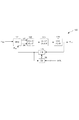
[0008]図1Aに、本発明による、現在動作する周波数源を用いる同調可能なシステムの例示的実施形態を示す。図示のように、同調可能なシステム100は、3つの周波数源FS1120、FS2130、及びFS3140を含み、その少なくとも1つ(FS1120など)は同調可能である。残りの周波数源は、システムの設計の必要又は要望に従って、固定周波数又は同調可能な周波数を生成するように動作してもよい。
[0008] FIG. 1A illustrates an exemplary embodiment of a tunable system using a currently operating frequency source in accordance with the present invention. As shown, the
[0009]図1Bに、本発明による、シグマデルタ型位相ロックループ(PLL)として実施される実施形態である、同調可能な周波数源の例を示す。このPLLは、バイポーラ相補型金属酸化膜半導体(Bi−CMOS)プロセスでモノリシックに製造され得るが、この回路は、別のプロセス又は材料(CMOS、SiGe、GaAsなど)を使って、モノリシック型、ハイブリッド型、又はディスクリート型として製造されてもよいことを当分野の技術者は理解するであろう。 [0009] FIG. 1B shows an example of a tunable frequency source, which is an embodiment implemented as a sigma-delta phase locked loop (PLL) according to the present invention. The PLL can be manufactured monolithically in a bipolar complementary metal oxide semiconductor (Bi-CMOS) process, but this circuit uses a different process or material (CMOS, SiGe, GaAs, etc.) to make it monolithic, hybrid Those skilled in the art will appreciate that the mold may be manufactured as a discrete mold.
[0010]図示のように、周波数源100は、位相周波数検出器121、チャージポンプ回路122、ループフィルタ123、選択可能なVCOバンクとして示される同調周波数源124、主N除算カウンタ125、及びプログラム可能なシグマデルタ型変調器126を含む。シグマデルタ型変調器126は、周波数設定制御信号CNTLを受け取り、これに応答して、N除算カウンタ125に、所望の分周比で到達する逓倍率制御データ信号を提供する。また、シグマデルタ型変調器126は、クロック信号としてのN除算(FDiv)信号も受け取り、それによってその動作をN除算カウンタ125と同期させる。
[0010] As shown, the
[0011]同調可能な周波数源FS1120は、位相ロックループとして示されているが、代替として、可変発振器、デジタル制御発振器など、他の同調可能な周波数源が用いられてもよい。固定周波数源が、L−C、誘電体共振器、水晶発振器などとして実施されてもよい。上記の例は例示にすぎず、本発明の代替の実施形態では、同調可能であれ、固定であれ、他の周波数源も使用され得ることを、当分野の技術者は理解するであろう。
[0011] Although the tunable
[0012]図2に、本発明による、予想信号及び/又は既存の信号を、位相プリングの影響を回避するのに十分な周波数分離を提供するように再配置する方法の例を示す。このプロセスは、まず212で、既存の信号の周波数に近接する周波数を有する予想信号が要求される。214で、予想信号の周波数が、既存の信号の周波数のプリング帯域幅内であるかどうか判定される。この動作の例示的実施形態では、出願人の同時係属出願「Multiple Frequency Source System and Method of Operation」の図3Cに示すようなデータベース構造にアクセスして、最も近接する既存の信号の周波数位置を決定し、これに基づいて、予想信号の周波数が既存の信号の周波数のプリング帯域幅内になるかどうか判定することができる。 [0012] FIG. 2 illustrates an example method of relocating an expected signal and / or an existing signal according to the present invention to provide sufficient frequency separation to avoid the effects of phase pulling. This process first requires 212 an expected signal having a frequency close to that of the existing signal. At 214, it is determined whether the frequency of the expected signal is within the pulling bandwidth of the frequency of the existing signal. In an exemplary embodiment of this operation, the database structure as shown in FIG. 3C of Applicant's co-pending application “Multiple Frequency Source System and Method of Operation” is accessed to determine the frequency location of the closest existing signal. Based on this, it can be determined whether the frequency of the expected signal is within the pulling bandwidth of the frequency of the existing signal.
[0013]本明細書で使用する際、「プリング帯域幅」という用語は、その範囲内に第2の信号が存在すると、対象となる信号を、それが既定の位相雑音レベルを超えるように「引き寄せ」、又は変調する閾値帯域幅を指す。対象信号のプリング帯域幅は、所望の位相雑音レベルと、いくつかの要因とに左右される。例えば、比較的高い品質(Q)係数を示す周波数源は、所与の位相雑音要件について比較的狭いプリング帯域幅を有する。同様に、近接する信号を生成する周波数源から高度に隔離されている周波数源も、同じ位相雑音要件について比較的狭いプリング帯域幅を有する。周波数源のQは、その構成とアーキテクチャに左右される。例えば、固定周波数の水晶又は誘電体共振発振器は、同調可能な発振器より高いQを示し得る。また、周波数源の(他の周波数源からの)隔離も、多重周波数源システムの構成とアーキテクチャに左右される。限度内では、無限大のQ、すなわち、近接する信号を生成する周波数源からの無限大の隔離を示す周波数源は、0Hzの位相プリング帯域幅を有するが、これらの条件は、特に、複数の同調可能な周波数源が、単一の集積回路上に実施される本発明の個別的実施形態では、獲得するのが不可能なはずである。したがって、既定のプリング帯域幅を定義するための特定の動作閾値が選択される。信号のプリング帯域幅の例示的実施形態には、500kHz未満、例えば、250kHz、100kHz、50kHz、又はそれより低い帯域幅と、500kHz超、例えば、600kHz、700kHz、800kHz、900kHz、1MHz、又はそれより高い帯域幅とが含まれる。 [0013] As used herein, the term "pulling bandwidth" refers to a signal of interest such that, when a second signal is within that range, it exceeds a predetermined phase noise level. “Draw” refers to the threshold bandwidth to be modulated. The pulling bandwidth of the signal of interest depends on the desired phase noise level and several factors. For example, a frequency source that exhibits a relatively high quality (Q) factor has a relatively narrow pulling bandwidth for a given phase noise requirement. Similarly, frequency sources that are highly isolated from frequency sources that produce adjacent signals also have a relatively narrow pulling bandwidth for the same phase noise requirements. The Q of the frequency source depends on its configuration and architecture. For example, a fixed frequency crystal or dielectric resonant oscillator may exhibit a higher Q than a tunable oscillator. The isolation of frequency sources (from other frequency sources) also depends on the configuration and architecture of the multi-frequency source system. Within limits, a frequency source that exhibits infinite Q, ie, infinite isolation from a frequency source that produces an adjacent signal, has a phase pulling bandwidth of 0 Hz, but these conditions are particularly In a particular embodiment of the invention where the tunable frequency source is implemented on a single integrated circuit, it should not be possible to obtain. Thus, a specific operating threshold is selected to define the default pulling bandwidth. Exemplary embodiments of signal pulling bandwidth include bandwidths below 500 kHz, eg, 250 kHz, 100 kHz, 50 kHz, or lower, and above 500 kHz, eg, 600 kHz, 700 kHz, 800 kHz, 900 kHz, 1 MHz, or more. High bandwidth is included.
[0014]一例として、システムが、特定の周波数オフセットにおいて−45dBcのSPURレベルを許容し得ると判定される場合、続いて、システムによって指定されるオフセットにおける所望の限度(LO精度)を達成するために、各周波数源の隔離とQが、(計算、実験、又は設計シミュレーションによって)選択される。例えば、LO精度は、±1MHzであると指定され、システムは、既存の信号の周波数から500kHzのオフセットにおいて−45dBcのSPURをもたらすような大きさであり、よって、プリング帯域幅は±500kHzであり、指定されるLO精度は、SPURレベルの若干のマージンを得るために、LOを、既存の周波数信号から500kHzより遠くに配置することを許容する。 [0014] As an example, if it is determined that the system can tolerate a SPUR level of -45 dBc at a particular frequency offset, then to achieve the desired limit (LO accuracy) at the offset specified by the system. In addition, the isolation and Q of each frequency source is selected (by calculation, experiment or design simulation). For example, the LO accuracy is specified to be ± 1 MHz, and the system is sized to provide a SPUR of −45 dBc at an offset of 500 kHz from the frequency of the existing signal, so the pulling bandwidth is ± 500 kHz. The specified LO accuracy allows to place the LO farther than 500 kHz from the existing frequency signal in order to obtain some margin of SPUR level.
[0015]214で、予想信号の周波数が、既存の信号の周波数の既定のプリング帯域幅内であると判定された場合、216で、既存の信号を生成する周波数源が同調可能であるかどうか判定される。既存の信号の周波数源が(その周波数源が固定周波数源であり、又は、同調可能な周波数源であるが、すでにその同調可能範囲の最大又は最小点に同調されているために)同調させることができない場合、プロセスは218に進み、その時点で、予想信号の周波数が、識別されたプリング帯域幅外の新しい予想周波数点に同調される。このプロセスは、例えば、プリング帯域幅外の周波数点が識別され、そこに予想周波数が同調される単一動作を使って行われてもよい。新しい予想周波数点は、例えば、最初に要求される予想周波数点から除去される最小限の周波数点であり、プリング帯域幅外にある周波数点を表し得る。代替として、動作216は、周波数源が第1の周波数点に同調され、任意選択で、第1の周波数点が、既存の信号のプリング帯域幅外であるかどうか判定するようにチェックし、そうでない場合、第2の別の除去された周波数点を識別し、そこに周波数源を同調させるための、2つ以上の同調動作を伴ってもよい。このように、予想信号は、(システムによって指定されるLO精度に従って)既存の信号からの必要な帯域幅分離が達成されるまで、既存の信号から徐々に離される。別の技法を使って予想信号がプリング帯域幅外に再配置されてもよいことを、当分野の技術者は理解するであろう。続いて222で、予想信号が、新しい予想周波数点で生成される。
[0015] If it is determined at 214 that the frequency of the expected signal is within a predetermined pulling bandwidth of the frequency of the existing signal, at 216, whether the frequency source that produces the existing signal is tunable. Determined. The frequency source of the existing signal is tuned (because the frequency source is a fixed frequency source or a tunable frequency source but is already tuned to the maximum or minimum point of its tunable range) If not, the process proceeds to 218, at which point the frequency of the expected signal is tuned to a new expected frequency point outside the identified pulling bandwidth. This process may be performed, for example, using a single operation in which a frequency point outside the pulling bandwidth is identified and the expected frequency is tuned there. The new expected frequency point is, for example, the minimum frequency point that is removed from the initially requested expected frequency point and may represent a frequency point that is outside the pulling bandwidth. Alternatively,
[0016]216で、既存の信号がその現在の範囲内で同調可能であると判定された場合、プロセスは220に進み、そこで、予想信号の周波数点が、以下の3つの動作の1つによって、プリング帯域幅内から除去される。すなわち、(i)予想信号の周波数が、既存の信号の周波数から離れた、プリング帯域幅外の新しい予想信号周波数点に同調される、(ii)既存の信号の周波数が、予想信号から離れたその現在の周波数点から、新しい既存の周波数点に同調される、又は(iii)(i)と(ii)の組合せであり、予想信号の周波数も既存の信号の周波数も、反対方向に、それぞれの新しい周波数点に同調され、新しい予想周波数点が、新しい既存の周波数点のプリング帯域幅外に位置するように、各信号が新しい周波数点に移動される。220で選択される個々のプロセス(i)〜(iii)は、周波数源の同調機能に応じて行われる。例えば、プロセス(i)は、既存の信号の周波数源が、周波数限界に位置し、それ以上予想信号から遠くに同調することができないとき、或いは、既存の信号が使用されており、又は妨げることのできない動作を行っている場合に用いられ得る。プロセス(ii)は、計算により、予想信号が、それ以上既存の信号から遠くに同調することができないときに使用され得る。プロセス(iii)は、両方の周波数源が、十分な同調許容度を有するときに使用することができ、このプロセスを用いて、必要な周波数間隔を得るために、各信号の元の同調点から必要とされる周波数オフセットを最小限に抑えることができる。個別的実施形態では、予想信号及び/又は既存の信号が、以下の図3に例示するように、交差しないように、他方から離して同調される。 [0016] If, at 216, it is determined that the existing signal is tunable within its current range, the process proceeds to 220, where the frequency point of the expected signal is determined by one of three actions: Removed from within the pulling bandwidth. (I) the frequency of the expected signal is tuned to a new expected signal frequency point outside the pulling bandwidth, away from the frequency of the existing signal, (ii) the frequency of the existing signal is away from the expected signal It is tuned from its current frequency point to a new existing frequency point, or (iii) a combination of (i) and (ii), both the frequency of the expected signal and the frequency of the existing signal in the opposite direction, respectively Each signal is moved to a new frequency point so that the new expected frequency point is outside the pulling bandwidth of the new existing frequency point. The individual processes (i) to (iii) selected at 220 are performed according to the tuning function of the frequency source. For example, process (i) may occur when the frequency source of the existing signal is located at the frequency limit and cannot be tuned further from the expected signal, or the existing signal is being used or disturbed. It can be used when an operation that cannot be performed is performed. Process (ii) may be used when the expected signal cannot be tuned further away from the existing signal by calculation. Process (iii) can be used when both frequency sources have sufficient tuning tolerance, and using this process, from the original tuning point of each signal to obtain the required frequency spacing. The required frequency offset can be minimized. In a particular embodiment, the expected signal and / or the existing signal is tuned away from the other so as not to cross, as illustrated in FIG. 3 below.
[0017]216の動作と同様に、222の動作は、単一動作としても、複数動作としても行われ得る。単一動作の例示的実施形態は、例えば、予想信号の周波数をプリング帯域幅外に配置するのに必要な帯域幅分離を提供する新しい周波数点を算出し、予想周波数と既存の周波数とを、それぞれの周波数点で生成することを含み得る。代替として、複数動作の手法では、一方又は両方の信号を相互から徐々に離し、任意選択で、結果として生じる帯域幅分離を、予想信号をプリング帯域幅外に配置するのに必要な帯域幅分離が獲得されているかどうか判定するようにチェックするための反復プロセスが実行されてもよい。既存の周波数信号が同調される実施形態では、既存の信号を生成し続けながら、その周波数源を、その元の周波数点から同調させても、既存の信号を非アクティブにし、その周波数源を、次の既存の周波数点に同調するように構成し、既存の信号を、その新しい周波数点で生成してもよい。継続して動作する既存の信号に徐々に同調する手法を用いれば、より大きい同調ステップを伴い得る大きい周波数オーバーシュートの影響の生成が回避されるという点で有利である。
[0017] Similar to
[0018]図3に、本発明による、予想信号が、周波数プリングを回避するのに十分な既存の周波数信号からの帯域幅分離を提供するように再配置される本発明の例示的実施形態を示す。既存の信号312が周波数点FE1で動作し、既存の信号の周波数は、これと関連付けられた既定のプリング帯域幅320を有する。続いて、予想信号322を、既存の周波数のプリング帯域幅320内の第1の予想周波数点FP1に同調させるよう求める要求が受け取られる。前述のように、プリング帯域幅は、一般に、周波数源のQ係数と、その周波数源と、近接する信号を生成する周波数源の間の隔離に左右される。一実施形態では、すべての周波数源が、実質的に同じQ係数と隔離を示し、したがって、各周波数源は、実質的に同じプリング帯域幅を有する。本発明の別の実施形態では、Q係数と隔離が、周波数源の1つ又は複数で異なり、したがって、プリング帯域幅は、同調する(第2の)周波数源が識別された後で決定される。
[0018] FIG. 3 illustrates an exemplary embodiment of the present invention in which an expected signal according to the present invention is repositioned to provide bandwidth separation from an existing frequency signal sufficient to avoid frequency pulling. Show. An existing
[0019]第1の予想周波数点FP1に同調するよう求める要求が、信号生成又はその信号への同調の前に受け取られると、FP1が、既存の信号312のプリング帯域幅320内にあるかどうか判定される(214)。図示の例では、FP1がプリング帯域幅320内にあり、前述のプロセスは216に進み、そこで、既存の信号312が同調可能な周波数源によって生成されるものかどうか判定される。例示のための本事例では、既存の信号312は、固定周波数源によって生成されるものと判定される。かかる場合、同調プロセスは218に進み、そこで、予想信号が、第1の周波数点FP1から離して、交差しないように第2の予想周波数点FP2に再配置される。218の同調動作は、さらに、FP2が、既存の信号312のプリング帯域幅320外にあると判定することを含む。プロセスは222に進み、そこで予想信号322が、第2の予想周波数点FP2で生成される。代替として、218のプロセスは、予想信号を、1つ又は複数のステップで既存の信号の周波数から徐々に離すように反復されてもよい。
[0019] When a request to tune to the first expected frequency point F P1 is received prior to signal generation or tuning to that signal, FP 1 is within the pulling
[0020]既存の周波数源が同調可能な代替の実施形態では、各周波数の再配置距離が、より少なくなるはずである。というのは、既存の信号312を(プリング帯域幅320のやはりわずかに高い周波数への移動も伴って)FE1のやや上に再配置すると共に、予想信号322をFT1のやや下に移動することにより、比較的小さい周波数シフトで必要な帯域幅分離が達成されることになるからである。かかるシステムの例示的実施形態では、シグマデルタ型位相ロックループなどの同調可能なシステムが、既存の信号と予想信号を生成する周波数源として使用され得る。別の例では、既存の周波数が、2つ以上のステップで反復して、予想信号から遠くに同調されて、信号の最終的な周波数への再配置を伴い得る周波数オーバーシュートの影響が低減される。 [0020] In an alternative embodiment where existing frequency sources can be tuned, the relocation distance for each frequency should be less. The existing signal 312 (with also the movement of the still slightly higher frequency of the pulling bandwidth 320) with slightly repositioned on the F E1, slightly moved under the expected signal 322 F T1 because This is because the necessary bandwidth separation is achieved with a relatively small frequency shift. In an exemplary embodiment of such a system, a tunable system such as a sigma delta phase-locked loop may be used as a frequency source that generates an existing signal and an expected signal. In another example, an existing frequency is iterated in two or more steps and tuned far from the expected signal to reduce the effects of frequency overshoot that can involve relocation of the signal to the final frequency. The
[0021]予想信号及び/又は既存の信号が再配置される本発明の実施形態では、周波数源は、信号の新しい周波数点への再配置の間、その信号を生成し続けてもよいことに留意すべきである。代替として、周波数源を非アクティブにし、新しい周波数(より高い周波数など)に同調するように構成し、新しい周波数点でその信号をアクティブ化することもできる。 [0021] In embodiments of the invention in which an expected signal and / or an existing signal is relocated, the frequency source may continue to generate that signal during relocation of the signal to a new frequency point. It should be noted. Alternatively, the frequency source can be deactivated and configured to tune to a new frequency (such as a higher frequency) and activate its signal at the new frequency point.
[0022]当分野の技術者であれば容易に理解するように、前述の各プロセスは、ハードウェア、ソフトウェア、ファームウェアとして、又は適宜これらの実装の組合せとして実施され得る。加えて、前述のプロセスの一部又は全部が、コンピュータ可読媒体(取り外し可能ディスク、揮発性又は不揮発性メモリ、埋込み式プロセッサなど)上にあるコンピュータ可読命令コードとして実施されてもよく、この命令コードは、他のかかるプログラム可能な装置のコンピュータを、目的の機能を実行するためにプログラムするように動作する。 [0022] As will be readily appreciated by those skilled in the art, each of the processes described above may be implemented as hardware, software, firmware, or a combination of these implementations as appropriate. In addition, some or all of the foregoing processes may be implemented as computer readable instruction code residing on a computer readable medium (removable disk, volatile or non-volatile memory, embedded processor, etc.). Operates to program the computer of another such programmable device to perform the intended function.
[0023]「a」又は「an」という語は、これによって記述される1つ、又は複数の特徴を指すのに使用されている。さらに、「coupled(結合された)」又は「connected(接続された)」という語は、直接的に、又は1つ又は複数の介在する構造又は物質を介して、(場合に応じて、電気的、機械的、熱的に)相互に組み合わさった特徴を指す。方法流れ図で言及される操作及び動作の順序は例示であり、これらの操作及び動作は、異なる順序で実行されてもよく、これらの操作及び動作の2つ以上が同時に実行されてもよい。本明細書で参照されるすべての出版物、特許その他の文献は、参照によりその全文が組み込まれるものである。任意のかかる組込み文献と本明細書の間での整合性を欠く用法に関しては、本明細書での用法が規定するものとする。 [0023] The terms "a" or "an" are used to refer to one or more features described thereby. In addition, the terms “coupled” or “connected” may be used directly or through one or more intervening structures or materials (as appropriate, electrical (Mechanical, thermal) refers to the combined characteristics of each other. The order of operations and operations referred to in the method flow diagrams are exemplary, and these operations and operations may be performed in different orders, and two or more of these operations and operations may be performed simultaneously. All publications, patents and other references referred to herein are incorporated by reference in their entirety. Any usage that lacks consistency between any such incorporated document and this specification shall be defined by the usage herein.
[0024]以上の記述は、図示と説明のために提示したものである。網羅的であることも、本発明を開示通りの形に限定することも意図しておらず、明らかに、開示の教示を考慮に入れれば、多くの変更及び変形が可能である。開示の実施形態は、本発明の原理と、その実際の適用を最も適切に説明し、それによって、当分野の技術者が、本発明を、様々な実施形態において、企図される個々の用途に適する様々な変更と共に最も適切に利用することを可能にするために選択されたものである。本発明の適用範囲は、添付の特許請求の範囲によって定義されるものである。 [0024] The foregoing description has been presented for purposes of illustration and description. It is not intended to be exhaustive or to limit the invention to the precise form disclosed, and obviously many modifications and variations are possible in light of the teachings of the disclosure. The disclosed embodiments best describe the principles of the invention and its practical application, so that those skilled in the art can use the invention in the various applications contemplated in various embodiments. It has been chosen to allow the most appropriate use with a variety of suitable changes. The scope of the present invention is defined by the appended claims.
Claims (17)
既存の周波数点の既存の信号であり、前記既存の周波数点の前後の既定のプリング帯域幅を有する前記既存の信号を含む第1の信号を生成するステップと、
前記既存の信号の前記既定のプリング帯域幅内の予想周波数点で予想信号を生成するよう求める要求を受け取るステップと、
前記既定のプリング帯域幅内から前記予想周波数点を除去するステップと、
前記予想信号と前記既存の信号とを、それぞれに対応する周波数点で生成するステップと
を含み、
前記既存の信号が固定周波数源を使って生成され、前記既定のプリング帯域幅内から前記予想周波数点を除去する前記ステップが、前記予想信号の周波数源を、前記既存の信号から離れた、前記既存の信号の前記既定のプリング帯域幅外に位置する新しい予想周波数点に同調させるステップを含み、
前記予想信号と前記既存の信号とを生成する前記ステップが、前記予想信号を前記新しい予想周波数点で生成し、前記既存の信号を前記既存の周波数点で生成するステップを含む、
方法。A method for mitigating phase pulling in a multi-frequency source system comprising:
Generating a first signal that is an existing signal at an existing frequency point and includes the existing signal having a predetermined pulling bandwidth before and after the existing frequency point;
Receiving a request to generate an expected signal at an expected frequency point within the predetermined pulling bandwidth of the existing signal;
Removing the expected frequency point from within the predetermined pulling bandwidth;
And said predicted signal and the existing signal, seen including a step of generating a frequency point corresponding to each,
The existing signal is generated using a fixed frequency source, and the step of removing the expected frequency point from within the predetermined pulling bandwidth separates the frequency source of the expected signal from the existing signal; Tuning to a new expected frequency point located outside the predetermined pulling bandwidth of an existing signal;
Generating the expected signal and the existing signal includes generating the expected signal at the new expected frequency point and generating the existing signal at the existing frequency point;
Method.
既存の周波数点の既存の信号であり、前記既存の周波数点の前後の既定のプリング帯域幅を有する前記既存の信号を含む第1の信号を生成するステップと、
前記既存の信号の前記既定のプリング帯域幅内の予想周波数点で予想信号を生成するよう求める要求を受け取るステップと、
前記既定のプリング帯域幅内から前記予想周波数点を除去するステップと、
前記予想信号と前記既存の信号とを、それぞれに対応する周波数点で生成するステップと
を含み、
前記既存の信号が同調可能な周波数源を使って生成され、前記既定のプリング帯域幅内から前記予想周波数点を除去する前記ステップが、前記既存の信号の周波数源を、前記予想周波数点から離れた新しい既存の周波数点に同調させて、前記既存の周波数点が前記新しい既存の周波数点に再配置された後で、前記予想周波数点が、前記既存の信号の前記既定のプリング帯域幅外に配置されるようにするステップを含み、
前記予想信号と前記既存の信号とを生成する前記ステップが、前記予想信号を前記予想周波数点で生成し、前記既存の信号を前記新しい既存の周波数点で生成するステップを含む、
方法。 A method for mitigating phase pulling in a multi-frequency source system comprising:
Generating a first signal that is an existing signal at an existing frequency point and includes the existing signal having a predetermined pulling bandwidth before and after the existing frequency point;
Receiving a request to generate an expected signal at an expected frequency point within the predetermined pulling bandwidth of the existing signal;
Removing the expected frequency point from within the predetermined pulling bandwidth;
Generating the expected signal and the existing signal at corresponding frequency points;
Including
The existing signal is generated using a tunable frequency source, and the step of removing the expected frequency point from within the predetermined pulling bandwidth separates the existing signal frequency source from the expected frequency point. After the existing frequency point is relocated to the new existing frequency point in tune to the new existing frequency point, the expected frequency point is outside the default pulling bandwidth of the existing signal. look including the step of to be placed,
Generating the expected signal and the existing signal comprises generating the expected signal at the expected frequency point and generating the existing signal at the new existing frequency point;
Way .
既存の周波数点の既存の信号であり、前記既存の周波数点の前後の既定のプリング帯域幅を有する前記既存の信号を含む第1の信号を生成するステップと、
前記既存の信号の前記既定のプリング帯域幅内の予想周波数点で予想信号を生成するよう求める要求を受け取るステップと、
前記既定のプリング帯域幅内から前記予想周波数点を除去するステップと、
前記予想信号と前記既存の信号とを、それぞれに対応する周波数点で生成するステップと
を含み、
前記既存の信号が同調可能な周波数源を使って生成され、前記既定のプリング帯域幅内から前記予想周波数点を除去する前記ステップが、前記予想信号の周波数源を、前記既存の信号から離れた新しい予想周波数点に同調させるステップを含み、
前記予想信号と前記既存の信号とを生成する前記ステップが、前記予想信号を前記新しい予想周波数点で生成し、前記既存の信号を前記既存の周波数点で生成するステップを含む、
方法。 A method for mitigating phase pulling in a multi-frequency source system comprising:
Generating a first signal that is an existing signal at an existing frequency point and includes the existing signal having a predetermined pulling bandwidth before and after the existing frequency point;
Receiving a request to generate an expected signal at an expected frequency point within the predetermined pulling bandwidth of the existing signal;
Removing the expected frequency point from within the predetermined pulling bandwidth;
Generating the expected signal and the existing signal at corresponding frequency points;
Including
The existing signal is generated using a tunable frequency source, and the step of removing the expected frequency point from within the predetermined pulling bandwidth separates the expected signal frequency source from the existing signal. the step of tuning to the new expected frequency points seen including,
Generating the expected signal and the existing signal includes generating the expected signal at the new expected frequency point and generating the existing signal at the existing frequency point;
Way .
既存の周波数点の既存の信号であり、前記既存の周波数点の前後の既定のプリング帯域幅を有する前記既存の信号を含む第1の信号を生成するステップと、
前記既存の信号の前記既定のプリング帯域幅内の予想周波数点で予想信号を生成するよう求める要求を受け取るステップと、
前記既定のプリング帯域幅内から前記予想周波数点を除去するステップと、
前記予想信号と前記既存の信号とを、それぞれに対応する周波数点で生成するステップと
を含み、
前記既存の信号が同調可能な周波数源を使って生成され、前記既定のプリング帯域幅内から前記予想周波数点を除去する前記ステップが、
前記予想信号の前記周波数源を、前記既存の周波数点から離れた新しい予想周波数点に同調させるステップと、
前記既存の信号の前記周波数源を、前記予想周波数点から離れた新しい既存の周波数点に同調させるステップと
を含み、
前記予想信号と前記既存の信号とを生成する前記ステップが、前記予想信号を前記新しい予想周波数点で生成し、前記既存の信号を前記新しい既存の周波数点で生成するステップを含む、
方法。 A method for mitigating phase pulling in a multi-frequency source system comprising:
Generating a first signal that is an existing signal at an existing frequency point and includes the existing signal having a predetermined pulling bandwidth before and after the existing frequency point;
Receiving a request to generate an expected signal at an expected frequency point within the predetermined pulling bandwidth of the existing signal;
Removing the expected frequency point from within the predetermined pulling bandwidth;
Generating the expected signal and the existing signal at corresponding frequency points;
Including
The step of generating the existing signal using a tunable frequency source and removing the expected frequency point from within the predetermined pulling bandwidth;
Tuning the frequency source of the expected signal to a new expected frequency point remote from the existing frequency point;
The frequency source of the existing signal, and a step of tuning to the new existing frequency point away from the expected frequency point,
Generating the expected signal and the existing signal includes generating the expected signal at the new expected frequency point and generating the existing signal at the new existing frequency point;
Way .
前記既存の信号の前記周波数源を同調させる前記ステップが、第2の位相ロックループを、前記新しい既存の周波数点で前記既存の信号を生成するように制御するステップを含む、請求項4に記載の方法。Tuning the frequency source of the expected signal includes controlling a first phase-locked loop to generate the expected signal at the new expected frequency point;
5. The method of claim 4 , wherein the step of tuning the frequency source of the existing signal includes controlling a second phase locked loop to generate the existing signal at the new existing frequency point. the method of.
既存の周波数点の既存の信号であり、前記既存の周波数点の前後の既定のプリング帯域幅を有する前記既存の信号を含む第1の信号を生成するステップと、
前記既存の信号の前記既定のプリング帯域幅内の予想周波数点で予想信号を生成するよう求める要求を受け取るステップと、
前記既定のプリング帯域幅内から前記予想周波数点を除去するステップと
を含み、
前記既定のプリング帯域幅内から前記予想周波数点を除去する前記ステップが、
前記予想信号を、前記既存の信号から離れる方向にある新しい予想周波数点に同調させるステップと、
前記既存の信号を、前記予想信号から離れる方向にある新しい既存の信号の周波数点に同調させるステップと、
前記予想信号と前記既存の信号とを、それぞれに対応する新しい周波数点で生成するステップと
を含む、方法。A method for mitigating phase pulling in a multi-frequency source system comprising:
Generating a first signal that is an existing signal at an existing frequency point and includes the existing signal having a predetermined pulling bandwidth before and after the existing frequency point;
Receiving a request to generate an expected signal at an expected frequency point within the predetermined pulling bandwidth of the existing signal;
Removing the expected frequency point from within the predetermined pulling bandwidth;
Removing the expected frequency point from within the predetermined pulling bandwidth;
Tuning the expected signal to a new expected frequency point in a direction away from the existing signal;
Tuning the existing signal to a frequency point of the new existing signal in a direction away from the expected signal;
Generating the expected signal and the existing signal at corresponding new frequency points.
前記既存の信号を新しい既存の周波数点に同調させる前記ステップが、第2の位相ロックループを、前記新しい既存の周波数点で前記既存の信号を生成するように制御するステップを含む、請求項6に記載の方法。Tuning the expected signal to a new expected frequency point includes controlling a first phase-locked loop to generate the expected signal at the new expected frequency point;
Wherein the step of tuning the existing signal to a new existing frequency point comprises controlling to the second phase locked loop to generate the existing signal at the new existing frequency point, claim 6 The method described in 1.
既存の周波数点の既存の信号であり、前記既存の周波数点の前後の既定のプリング帯域幅を有する前記既存の信号を含む第1の信号を生成する固定周波数源と、
前記既存の信号の前記既定のプリング帯域幅内の予想周波数点で予想信号を生成するよう求める要求を受け取る手段と、
前記既定のプリング帯域幅内から前記予想周波数点を除去する手段と、
前記予想信号と前記既存の信号とを、それぞれに対応する周波数点で生成する手段と
を備え、
前記既定のプリング帯域幅内から前記予想周波数点を除去する前記手段が、前記予想信号の周波数源を、前記既存の信号から離れた、前記既存の信号の前記既定のプリング帯域幅外に位置する新しい予想周波数点に同調させる手段を備え、
前記予想信号と前記既存の信号とを生成する前記手段が、前記予想信号を前記新しい予想周波数点で生成し、前記既存の信号を前記既存の周波数点で生成する手段を備える、
システム。A system for mitigating phase pulling in a multi-frequency source system,
A fixed frequency source for generating a first signal that is an existing signal at an existing frequency point and includes the existing signal having a predetermined pulling bandwidth before and after the existing frequency point;
Means for receiving a request to generate an expected signal at an expected frequency point within the predetermined pulling bandwidth of the existing signal;
Means for removing the expected frequency point from within the predetermined pulling bandwidth;
Means for generating the expected signal and the existing signal at corresponding frequency points ;
The means for removing the expected frequency point from within the predetermined pulling bandwidth locates the frequency source of the predicted signal outside the predetermined pulling bandwidth of the existing signal, away from the existing signal. With means to tune to the new expected frequency point,
The means for generating the expected signal and the existing signal comprises means for generating the expected signal at the new expected frequency point and generating the existing signal at the existing frequency point;
system.
既存の周波数点の既存の信号であり、前記既存の周波数点の前後の既定のプリング帯域幅を有する前記既存の信号を含む第1の信号を生成する同調可能な周波数源と、
前記既存の信号の前記既定のプリング帯域幅内の予想周波数点で予想信号を生成するよう求める要求を受け取る手段と、
前記既定のプリング帯域幅内から前記予想周波数点を除去する手段と、
前記予想信号と前記既存の信号とを、それぞれに対応する周波数点で生成する手段と
を備え、
前記既定のプリング帯域幅内から前記予想周波数点を除去する前記手段が、前記既存の信号の前記同調可能な周波数源を、予想周波数点から離れた新しい既存の周波数点に同調させて、前記既存の周波数点が前記新しい既存の周波数点に再配置された後で、前記予想周波数点が、前記既存の信号の前記既定のプリング帯域幅外に配置されるようにする手段を備え、
前記予想信号と前記既存の信号とを生成する前記手段が、前記予想信号を前記予想周波数点で生成し、前記既存の信号を前記新しい既存の周波数点で生成する手段を備える、
システム。 A system for mitigating phase pulling in a multi-frequency source system,
A tunable frequency source that generates a first signal that is an existing signal at an existing frequency point and that includes a pre-existing signal having a predetermined pulling bandwidth before and after the existing frequency point;
Means for receiving a request to generate an expected signal at an expected frequency point within the predetermined pulling bandwidth of the existing signal;
Means for removing the expected frequency point from within the predetermined pulling bandwidth;
Means for generating the expected signal and the existing signal at corresponding frequency points;
With
The means for removing the expected frequency point from within the predetermined pulling bandwidth tunes the tunable frequency source of the existing signal to a new existing frequency point that is remote from the expected frequency point. in after the frequency point is relocated to the new existing frequency point, the expected frequency point is provided with a means to be placed in the outer predefined pulling bandwidth of the existing signal,
The means for generating the expected signal and the existing signal comprises means for generating the expected signal at the expected frequency point and generating the existing signal at the new existing frequency point;
System .
既存の周波数点の既存の信号であり、前記既存の周波数点の前後の既定のプリング帯域幅を有する前記既存の信号を含む第1の信号を生成する同調可能な周波数源と、
前記既存の信号の前記既定のプリング帯域幅内の予想周波数点で予想信号を生成するよう求める要求を受け取る手段と、
前記既定のプリング帯域幅内から前記予想周波数点を除去する手段と、
前記予想信号と前記既存の信号とを、それぞれに対応する周波数点で生成する手段と
を備え、
前記既定のプリング帯域幅内から前記予想周波数点を除去する前記手段が、前記予想信号の周波数源を、前記既存の信号から離れた新しい予想周波数点に同調させる手段を
備え、
前記予想信号と前記既存の信号とを生成する前記手段が、前記予想信号を前記新しい予想周波数点で生成し、前記既存の信号を前記既存の周波数点で生成する手段を備える、
システム。 A system for mitigating phase pulling in a multi-frequency source system,
A tunable frequency source that generates a first signal that is an existing signal at an existing frequency point and that includes a pre-existing signal having a predetermined pulling bandwidth before and after the existing frequency point;
Means for receiving a request to generate an expected signal at an expected frequency point within the predetermined pulling bandwidth of the existing signal;
Means for removing the expected frequency point from within the predetermined pulling bandwidth;
Means for generating the expected signal and the existing signal at corresponding frequency points;
With
Means for removing the expected frequency point from within the predetermined pulling bandwidth means for tuning a frequency source of the expected signal to a new expected frequency point remote from the existing signal;
Prepared ,
The means for generating the expected signal and the existing signal comprises means for generating the expected signal at the new expected frequency point and generating the existing signal at the existing frequency point;
System .
既存の周波数点の既存の信号であり、前記既存の周波数点の前後の既定のプリング帯域幅を有する前記既存の信号を含む第1の信号を生成する同調可能な周波数源と、
前記既存の信号の前記既定のプリング帯域幅内の予想周波数点で予想信号を生成するよう求める要求を受け取る手段と、
前記既定のプリング帯域幅内から前記予想周波数点を除去する手段と、
前記予想信号と前記既存の信号とを、それぞれに対応する周波数点で生成する手段と
を備え、
前記既定のプリング帯域幅内から前記予想周波数点を除去する前記手段が、
前記予想信号の周波数源を、前記既存の周波数点から離れた新しい予想周波数点に同調させる手段と、
前記既存の信号の前記同調可能な周波数源を、前記予想周波数点から離れた新しい既存の周波数点に同調させる手段と
を備え、
前記予想信号と前記既存の信号とを生成する前記手段が、前記予想信号を前記新しい予想周波数点で生成し、前記既存の信号を前記新しい既存の周波数点で生成する手段を備える、
システム。 A system for mitigating phase pulling in a multi-frequency source system,
A tunable frequency source that generates a first signal that is an existing signal at an existing frequency point and that includes a pre-existing signal having a predetermined pulling bandwidth before and after the existing frequency point;
Means for receiving a request to generate an expected signal at an expected frequency point within the predetermined pulling bandwidth of the existing signal;
Means for removing the expected frequency point from within the predetermined pulling bandwidth;
Means for generating the expected signal and the existing signal at corresponding frequency points;
With
The means for removing the expected frequency point from within the predetermined pulling bandwidth;
Means for tuning the frequency source of the expected signal to a new expected frequency point remote from the existing frequency point;
Wherein the tunable frequency source of the existing signal, and means for tuning to a new existing frequency point away from the expected frequency point,
The means for generating the expected signal and the existing signal comprises means for generating the expected signal at the new expected frequency point and generating the existing signal at the new existing frequency point;
System .
前記既存の信号の前記周波数源を同調させる前記手段が、前記新しい既存の周波数点で前記既存の信号を生成するように動作する第2の位相ロックループを備える、請求項11に記載のシステム。The means for tuning the frequency source of the expected signal comprises a first phase-locked loop that operates to generate the expected signal at the new expected frequency point;
The system of claim 11 , wherein the means for tuning the frequency source of the existing signal comprises a second phase-locked loop that operates to generate the existing signal at the new existing frequency point.
既存の周波数点の既存の信号であり、前記既存の周波数点の前後の既定のプリング帯域幅を有する前記既存の信号を含む第1の信号を、固定周波数源を使って生成する命令コードと、
前記既存の信号の前記既定のプリング帯域幅内の予想周波数点で予想信号を生成するよう求める要求を受け取る命令コードと、
前記既定のプリング帯域幅内から前記予想周波数点を除去する命令コードと、
前記予想信号と前記既存の信号とを、それぞれに対応する周波数点で生成する命令コードと
を備え、
前記既定のプリング帯域幅内から前記予想周波数点を除去する前記命令コードが、前記予想信号の周波数源を、前記既存の信号から離れた、前記既存の信号の前記既定のプリング帯域幅外に位置する新しい予想周波数点に同調させる命令コードを備え、
前記予想信号と前記既存の信号とを生成する前記命令コードが、前記予想信号を前記新しい予想周波数点で生成し、前記既存の信号を前記既存の周波数点で生成する命令コードを備える、
コンピュータプログラム製品。A computer program product on a computer readable medium and operable to control a programmable system to mitigate phase pulling in a multi-frequency source system,
An instruction code for generating , using a fixed frequency source, a first signal that is an existing signal at an existing frequency point and includes the existing signal having a predetermined pulling bandwidth before and after the existing frequency point;
An instruction code for receiving a request to generate an expected signal at an expected frequency point within the predetermined pulling bandwidth of the existing signal;
An instruction code for removing the expected frequency point from within the predetermined pulling bandwidth;
An instruction code for generating the expected signal and the existing signal at frequency points corresponding to each of the expected signal and the existing signal ,
The instruction code for removing the expected frequency point from within the predetermined pulling bandwidth is located outside the predetermined pulling bandwidth of the existing signal, the frequency source of the expected signal being remote from the existing signal. With an instruction code to tune to the new expected frequency point
The instruction code for generating the expected signal and the existing signal comprises an instruction code for generating the expected signal at the new expected frequency point and generating the existing signal at the existing frequency point.
Computer program product.
既存の周波数点の既存の信号であり、前記既存の周波数点の前後の既定のプリング帯域幅を有する前記既存の信号を含む第1の信号を、同調可能な周波数源を使って生成する命令コードと、
前記既存の信号の前記既定のプリング帯域幅内の予想周波数点で予想信号を生成するよう求める要求を受け取る命令コードと、
前記既定のプリング帯域幅内から前記予想周波数点を除去する命令コードと、
前記予想信号と前記既存の信号とを、それぞれに対応する周波数点で生成する命令コードと
を備え、
前記既定のプリング帯域幅内から前記予想周波数点を除去する前記命令コードが、前記既存の信号の前記周波数源を、前記予想周波数点から離れた新しい既存の周波数点に同調させて、前記既存の周波数点が前記新しい既存の周波数点に再配置された後で、前記予想周波数点が、前記既存の信号の前記既定のプリング帯域幅外に配置されるようにする命令コードを備え、
前記予想信号と前記既存の信号とを生成する前記命令コードが、前記予想信号を前記予想周波数点で生成し、前記既存の信号を前記新しい既存の周波数点で生成する命令コードを備える、
コンピュータプログラム製品。 A computer program product on a computer readable medium and operable to control a programmable system to mitigate phase pulling in a multi-frequency source system,
Instruction code for generating a first signal that is an existing signal at an existing frequency point and includes the existing signal having a predetermined pulling bandwidth before and after the existing frequency point using a tunable frequency source When,
An instruction code for receiving a request to generate an expected signal at an expected frequency point within the predetermined pulling bandwidth of the existing signal;
An instruction code for removing the expected frequency point from within the predetermined pulling bandwidth;
An instruction code for generating the expected signal and the existing signal at frequency points corresponding to each of the expected signal and the existing signal;
With
The instruction code for removing the expected frequency point from within the predetermined pulling bandwidth tunes the frequency source of the existing signal to a new existing frequency point away from the expected frequency point to after the frequency point is relocated to the new existing frequency point, the expected frequency point comprises an instruction code to be placed in the outer predefined pulling bandwidth of the existing signal,
The instruction code for generating the expected signal and the existing signal comprises an instruction code for generating the expected signal at the expected frequency point and generating the existing signal at the new existing frequency point.
Computer program product .
既存の周波数点の既存の信号であり、前記既存の周波数点の前後の既定のプリング帯域幅を有する前記既存の信号を含む第1の信号を、同調可能な周波数源を使って生成する命令コードと、
前記既存の信号の前記既定のプリング帯域幅内の予想周波数点で予想信号を生成するよう求める要求を受け取る命令コードと、
前記既定のプリング帯域幅内から前記予想周波数点を除去する命令コードと、
前記予想信号と前記既存の信号とを、それぞれに対応する周波数点で生成する命令コードと
を備え、
前記既定のプリング帯域幅内から前記予想周波数点を除去する前記命令コードが、前記予想信号の周波数源を、前記既存の信号から離れた新しい予想周波数点に同調させる命令コードを備え、
前記予想信号と前記既存の信号とを生成する前記命令コードが、前記予想信号を前記新しい予想周波数点で生成し、前記既存の信号を前記既存の周波数点で生成する命令コードを備える、
コンピュータプログラム製品。 A computer program product on a computer readable medium and operable to control a programmable system to mitigate phase pulling in a multi-frequency source system,
Instruction code for generating a first signal that is an existing signal at an existing frequency point and includes the existing signal having a predetermined pulling bandwidth before and after the existing frequency point using a tunable frequency source When,
An instruction code for receiving a request to generate an expected signal at an expected frequency point within the predetermined pulling bandwidth of the existing signal;
An instruction code for removing the expected frequency point from within the predetermined pulling bandwidth;
An instruction code for generating the expected signal and the existing signal at frequency points corresponding to each of the expected signal and the existing signal;
With
The instruction code to remove the estimated frequency point from within the predefined pulling bandwidth, the frequency source of the predicted signal comprises instruction code to tune to the new expected frequency point away from the existing signal,
The instruction code for generating the expected signal and the existing signal comprises an instruction code for generating the expected signal at the new expected frequency point and generating the existing signal at the existing frequency point.
Computer program product .
既存の周波数点の既存の信号であり、前記既存の周波数点の前後の既定のプリング帯域幅を有する前記既存の信号を含む第1の信号を、同調可能な周波数源を使って生成する命令コードと、
前記既存の信号の前記既定のプリング帯域幅内の予想周波数点で予想信号を生成するよう求める要求を受け取る命令コードと、
前記既定のプリング帯域幅内から前記予想周波数点を除去する命令コードと、
前記予想信号と前記既存の信号とを、それぞれに対応する周波数点で生成する命令コードと
を備え、
前記既定のプリング帯域幅内から前記予想周波数点を除去する前記命令コードが、
前記予想信号の周波数源を、前記既存の周波数点から離れた新しい予想周波数点に同調させる命令コードと、
前記既存の信号の前記周波数源を、前記予想周波数点から離れた新しい既存の周波数点に同調させる命令コードと
を備え、
前記予想信号と前記既存の信号とを生成する前記命令コードが、前記予想信号を前記新しい予想周波数点で生成し、前記既存の信号を前記新しい既存の周波数点で生成する命令コードを備える、
コンピュータプログラム製品。 A computer program product on a computer readable medium and operable to control a programmable system to mitigate phase pulling in a multi-frequency source system,
Instruction code for generating a first signal that is an existing signal at an existing frequency point and includes the existing signal having a predetermined pulling bandwidth before and after the existing frequency point using a tunable frequency source When,
An instruction code for receiving a request to generate an expected signal at an expected frequency point within the predetermined pulling bandwidth of the existing signal;
An instruction code for removing the expected frequency point from within the predetermined pulling bandwidth;
An instruction code for generating the expected signal and the existing signal at frequency points corresponding to each of the expected signal and the existing signal;
With
The instruction code for removing the expected frequency point from within the predetermined pulling bandwidth;
An instruction code for tuning the frequency source of the expected signal to a new expected frequency point remote from the existing frequency point;
The frequency source of the existing signal, and a command code to tune to the new existing frequency point away from the expected frequency point,
The instruction code for generating the expected signal and the existing signal comprises an instruction code for generating the expected signal at the new expected frequency point and generating the existing signal at the new existing frequency point.
Computer program product .
前記既存の信号の前記周波数源を同調させる前記命令コードが、第2の位相ロックループを、前記新しい既存の周波数点で前記既存の信号を生成するように制御する命令コードを備える、請求項16に記載のコンピュータプログラム製品。The instruction code for tuning the frequency source of the expected signal comprises an instruction code for controlling a first phase locked loop to generate the expected signal at the new expected frequency point;
The instruction code to tune the frequency source of the existing signal comprises instruction codes a second phase locked loop is controlled to generate the existing signal at the new existing frequency point, claim 16 A computer program product as described in.
Applications Claiming Priority (4)
| Application Number | Priority Date | Filing Date | Title |
|---|---|---|---|
| US59575405P | 2005-08-02 | 2005-08-02 | |
| US59574905P | 2005-08-02 | 2005-08-02 | |
| US59575005P | 2005-08-02 | 2005-08-02 | |
| PCT/IB2006/052634 WO2007015211A2 (en) | 2005-08-02 | 2006-08-01 | System and method for mitigating phase pulling in a multiple frequency source system |
Publications (2)
| Publication Number | Publication Date |
|---|---|
| JP2009508369A JP2009508369A (en) | 2009-02-26 |
| JP4245658B2 true JP4245658B2 (en) | 2009-03-25 |
Family
ID=37467507
Family Applications (3)
| Application Number | Title | Priority Date | Filing Date |
|---|---|---|---|
| JP2008524657A Expired - Fee Related JP4395541B2 (en) | 2005-08-02 | 2006-08-01 | Multi-frequency source system and method of operation |
| JP2008524659A Expired - Fee Related JP4245658B2 (en) | 2005-08-02 | 2006-08-01 | System and method for mitigating phase pulling in a multi-frequency source system |
| JP2008524658A Pending JP2009504064A (en) | 2005-08-02 | 2006-08-01 | Offset signal phase adjustment for multi-frequency source systems |
Family Applications Before (1)
| Application Number | Title | Priority Date | Filing Date |
|---|---|---|---|
| JP2008524657A Expired - Fee Related JP4395541B2 (en) | 2005-08-02 | 2006-08-01 | Multi-frequency source system and method of operation |
Family Applications After (1)
| Application Number | Title | Priority Date | Filing Date |
|---|---|---|---|
| JP2008524658A Pending JP2009504064A (en) | 2005-08-02 | 2006-08-01 | Offset signal phase adjustment for multi-frequency source systems |
Country Status (6)
| Country | Link |
|---|---|
| US (3) | US7528665B2 (en) |
| EP (3) | EP1911159A1 (en) |
| JP (3) | JP4395541B2 (en) |
| KR (4) | KR100853047B1 (en) |
| AT (1) | ATE535065T1 (en) |
| WO (3) | WO2007015209A1 (en) |
Families Citing this family (18)
| Publication number | Priority date | Publication date | Assignee | Title |
|---|---|---|---|---|
| US7783467B2 (en) * | 2005-12-10 | 2010-08-24 | Electronics And Telecommunications Research Institute | Method for digital system modeling by using higher software simulator |
| US7474167B1 (en) * | 2006-08-31 | 2009-01-06 | Altera Corporation | Capacitance switch circuitry for digitally controlled oscillators |
| US7869781B2 (en) | 2006-12-06 | 2011-01-11 | Broadcom Corporation | Method and system for mitigating the effects of pulling in multiple phase locked loops in multi-standard systems |
| US20080143192A1 (en) * | 2006-12-14 | 2008-06-19 | Sample Alanson P | Dynamic radio frequency power harvesting |
| CN101197573B (en) * | 2007-01-10 | 2010-12-29 | 晨星半导体股份有限公司 | Clock pulse generator, self testing and switch control method used on the same |
| JP2009010599A (en) * | 2007-06-27 | 2009-01-15 | Panasonic Corp | Digitally controlled oscillator circuit, frequency synthesizer, radio communication device using the same and its controlling method |
| US8212610B2 (en) * | 2008-09-19 | 2012-07-03 | Altera Corporation | Techniques for digital loop filters |
| KR101467417B1 (en) * | 2008-12-30 | 2014-12-11 | 주식회사 동부하이텍 | digital synchronous circuits |
| US20100250746A1 (en) * | 2009-03-30 | 2010-09-30 | Hitachi, Ltd. | Information technology source migration |
| JP5148548B2 (en) * | 2009-04-17 | 2013-02-20 | 株式会社東芝 | Digital PLL circuit and semiconductor integrated circuit |
| JP5367075B2 (en) * | 2009-05-22 | 2013-12-11 | パナソニック株式会社 | PLL frequency synthesizer |
| US8756451B2 (en) * | 2011-10-01 | 2014-06-17 | Intel Corporation | Frequency synthesis methods and systems |
| US8692594B2 (en) * | 2011-12-19 | 2014-04-08 | Ati Technologies Ulc | Phase-locked loop frequency stepping |
| US9166604B2 (en) * | 2012-04-25 | 2015-10-20 | Infineon Technologies Ag | Timing monitor for PLL |
| US9490825B2 (en) * | 2013-05-23 | 2016-11-08 | Intel IP Corporation | Adjusting tuning segments in a digitally-controlled oscillator |
| US9509353B2 (en) | 2014-08-20 | 2016-11-29 | Nxp B.V. | Data processing device |
| GB201800174D0 (en) * | 2018-01-05 | 2018-02-21 | Kirintec Ltd | Receiver |
| CN111508416B (en) * | 2020-04-30 | 2021-09-03 | 武汉华星光电半导体显示技术有限公司 | Display and driving method thereof |
Family Cites Families (39)
| Publication number | Priority date | Publication date | Assignee | Title |
|---|---|---|---|---|
| JPS6120420A (en) * | 1984-07-06 | 1986-01-29 | Nec Corp | Polyphase clock generating circuit |
| JP2541313B2 (en) * | 1989-07-29 | 1996-10-09 | 日本電気株式会社 | Dual PLL device |
| US5452290A (en) | 1992-10-26 | 1995-09-19 | Motorola, Inc. | Look ahead channel switching transceiver |
| US5408196A (en) | 1993-03-29 | 1995-04-18 | U.S. Philips Corporation | Tunable device |
| US6334219B1 (en) * | 1994-09-26 | 2001-12-25 | Adc Telecommunications Inc. | Channel selection for a hybrid fiber coax network |
| US7339078B2 (en) * | 1995-03-10 | 2008-03-04 | G.D. Searle Llc | Bis-amino acid hydroxyethylamino sulfonamide retroviral protease inhibitors |
| US6177964B1 (en) * | 1997-08-01 | 2001-01-23 | Microtune, Inc. | Broadband integrated television tuner |
| JP3453006B2 (en) * | 1995-07-07 | 2003-10-06 | パイオニア株式会社 | Phase synchronization circuit and digital signal reproducing device |
| US5774701A (en) * | 1995-07-10 | 1998-06-30 | Hitachi, Ltd. | Microprocessor operating at high and low clok frequencies |
| US5565816A (en) * | 1995-08-18 | 1996-10-15 | International Business Machines Corporation | Clock distribution network |
| JPH09246967A (en) * | 1996-03-04 | 1997-09-19 | Casio Comput Co Ltd | Pll frequency synthesizer circuit |
| JP3323054B2 (en) * | 1996-04-01 | 2002-09-09 | 株式会社東芝 | Frequency multiplier |
| JP3596172B2 (en) * | 1996-06-19 | 2004-12-02 | 富士通株式会社 | PLL frequency synthesizer |
| JPH10270999A (en) * | 1997-03-24 | 1998-10-09 | Seiko Epson Corp | Semiconductor device |
| JP3279957B2 (en) * | 1997-05-23 | 2002-04-30 | 松下電器産業株式会社 | Portable wireless devices |
| JPH11205101A (en) * | 1998-01-13 | 1999-07-30 | Toshiba Corp | Phase followup device |
| US6112308A (en) * | 1998-01-23 | 2000-08-29 | Intel Corporation | Cascaded multiple internal phase-locked loops for synchronization of hierarchically distinct chipset components and subsystems |
| SE513950C2 (en) * | 1998-02-12 | 2000-12-04 | Ericsson Telefon Ab L M | Method and apparatus of a mobile telecommunication network to provide a multi-channel connection |
| US6628779B1 (en) | 1998-05-11 | 2003-09-30 | Telcordia Technologies, Inc. | Method and system for scaleable near-end speech cancellation for tip and ring tone signal detectors |
| US6304146B1 (en) | 1998-05-29 | 2001-10-16 | Silicon Laboratories, Inc. | Method and apparatus for synthesizing dual band high-frequency signals for wireless communications |
| JP2000286704A (en) * | 1999-01-28 | 2000-10-13 | Matsushita Electric Ind Co Ltd | Frequency synthesizer device and mobile radio equipment using the same |
| EP1045606A3 (en) * | 1999-04-15 | 2001-08-29 | Texas Instruments Incorporated | Method and device for a multiple access wireless communication system |
| US6147561A (en) * | 1999-07-29 | 2000-11-14 | Conexant Systems, Inc. | Phase/frequency detector with time-delayed inputs in a charge pump based phase locked loop and a method for enhancing the phase locked loop gain |
| TW496035B (en) | 2000-04-25 | 2002-07-21 | Univ Singapore | Method and apparatus for a digital clock multiplication circuit |
| JP2001332969A (en) * | 2000-05-23 | 2001-11-30 | Nec Microsystems Ltd | Oscillator |
| US6686803B1 (en) * | 2000-07-10 | 2004-02-03 | Silicon Laboratories, Inc. | Integrated circuit incorporating circuitry for determining which of at least two possible frequencies is present on an externally provided reference signal and method therefor |
| JP4454810B2 (en) * | 2000-08-04 | 2010-04-21 | Necエレクトロニクス株式会社 | Digital phase control method and digital phase control circuit |
| DE10102725C2 (en) | 2001-01-22 | 2003-04-24 | Infineon Technologies Ag | Method for operating a PLL frequency synthesis circuit |
| JP2003133950A (en) * | 2001-10-24 | 2003-05-09 | Nippon Dempa Kogyo Co Ltd | Voltage controlled oscillator with input changeover switch and pll control oscillator |
| EP1318641A3 (en) * | 2001-12-10 | 2006-10-04 | Alps Electric Co., Ltd. | Carrier recovery with antenna diversity |
| US7062229B2 (en) * | 2002-03-06 | 2006-06-13 | Qualcomm Incorporated | Discrete amplitude calibration of oscillators in frequency synthesizers |
| US20030179842A1 (en) * | 2002-03-22 | 2003-09-25 | Kane Michael G. | Digital pattern sequence generator |
| JP2004072714A (en) * | 2002-06-11 | 2004-03-04 | Rohm Co Ltd | Clock generating system |
| KR100465455B1 (en) | 2002-06-24 | 2005-01-13 | 씨제이 주식회사 | Thioxo thiazole derivatives, processes for the preparation thereof, and pharmaceutical compositions containing the same |
| US20040006850A1 (en) | 2002-07-09 | 2004-01-15 | Wax David B. | Personal pen retaining system |
| JP4164301B2 (en) * | 2002-07-16 | 2008-10-15 | 株式会社日立製作所 | Multi-frequency PLL oscillator and multi-frequency CW radar using the same |
| WO2004082277A1 (en) * | 2003-03-11 | 2004-09-23 | Thomson Licensing S.A. | Apparatus and method for distributing signals |
| US6954093B2 (en) | 2003-03-27 | 2005-10-11 | Micronas Gmbh | Clocking scheme and clock system for a monolithic integrated circuit |
| JP2006180398A (en) * | 2004-12-24 | 2006-07-06 | Toshiba Corp | Clock-generating device and method |
-
2006
- 2006-08-01 WO PCT/IB2006/052632 patent/WO2007015209A1/en active Application Filing
- 2006-08-01 JP JP2008524657A patent/JP4395541B2/en not_active Expired - Fee Related
- 2006-08-01 WO PCT/IB2006/052634 patent/WO2007015211A2/en active Application Filing
- 2006-08-01 EP EP06766077A patent/EP1911159A1/en not_active Withdrawn
- 2006-08-01 JP JP2008524659A patent/JP4245658B2/en not_active Expired - Fee Related
- 2006-08-01 AT AT06780271T patent/ATE535065T1/en active
- 2006-08-01 US US11/461,530 patent/US7528665B2/en not_active Expired - Fee Related
- 2006-08-01 EP EP06766078A patent/EP1910908A1/en not_active Withdrawn
- 2006-08-01 EP EP06780271A patent/EP1911185B1/en not_active Not-in-force
- 2006-08-01 KR KR1020087002866A patent/KR100853047B1/en not_active IP Right Cessation
- 2006-08-01 KR KR1020087005222A patent/KR100967723B1/en not_active IP Right Cessation
- 2006-08-01 US US11/461,534 patent/US7355483B2/en not_active Expired - Fee Related
- 2006-08-01 KR KR1020087003990A patent/KR100917085B1/en not_active IP Right Cessation
- 2006-08-01 JP JP2008524658A patent/JP2009504064A/en active Pending
- 2006-08-01 WO PCT/IB2006/052633 patent/WO2007015210A1/en active Application Filing
- 2006-08-01 US US11/461,533 patent/US7653370B2/en not_active Expired - Fee Related
- 2006-08-01 KR KR1020097009988A patent/KR100966926B1/en not_active IP Right Cessation
Also Published As
| Publication number | Publication date |
|---|---|
| KR20080023760A (en) | 2008-03-14 |
| US7653370B2 (en) | 2010-01-26 |
| KR100966926B1 (en) | 2010-06-29 |
| US7355483B2 (en) | 2008-04-08 |
| KR100853047B1 (en) | 2008-08-19 |
| KR20080031503A (en) | 2008-04-08 |
| ATE535065T1 (en) | 2011-12-15 |
| KR20080025766A (en) | 2008-03-21 |
| JP2009508369A (en) | 2009-02-26 |
| JP2009504064A (en) | 2009-01-29 |
| WO2007015211A2 (en) | 2007-02-08 |
| EP1911185A2 (en) | 2008-04-16 |
| JP4395541B2 (en) | 2010-01-13 |
| US20070176663A1 (en) | 2007-08-02 |
| EP1911159A1 (en) | 2008-04-16 |
| WO2007015211A3 (en) | 2007-04-19 |
| JP2009504063A (en) | 2009-01-29 |
| KR100917085B1 (en) | 2009-09-15 |
| US7528665B2 (en) | 2009-05-05 |
| EP1911185B1 (en) | 2011-11-23 |
| WO2007015209A1 (en) | 2007-02-08 |
| EP1910908A1 (en) | 2008-04-16 |
| KR20090058593A (en) | 2009-06-09 |
| US20070200640A1 (en) | 2007-08-30 |
| KR100967723B1 (en) | 2010-07-05 |
| US20070183014A1 (en) | 2007-08-09 |
| WO2007015210A1 (en) | 2007-02-08 |
Similar Documents
| Publication | Publication Date | Title |
|---|---|---|
| JP4245658B2 (en) | System and method for mitigating phase pulling in a multi-frequency source system | |
| US8441291B2 (en) | PLL using interpolative divider as digitally controlled oscillator | |
| US8305115B2 (en) | Elimination of fractional N boundary spurs in a signal synthesizer | |
| US10651858B2 (en) | Synthesizer and phase frequency detector | |
| US7564280B2 (en) | Phase locked loop with small size and improved performance | |
| US7298218B2 (en) | Frequency synthesizer architecture | |
| US9219487B1 (en) | Frequency ramp generation in PLL based RF frontend | |
| US9312867B2 (en) | Phase lock loop device with correcting function of loop bandwidth and method thereof | |
| CA2670521C (en) | System and method for reducing transient responses in a phase lock loop with variable oscillator gain | |
| CN109995362B (en) | Phase-locked loop integrated circuit | |
| KR102335966B1 (en) | Multi vco apparatus using phase locked loop circuit for outputting multi-synchronizing signals | |
| US8274337B2 (en) | Digital phase locked loop | |
| KR20180131017A (en) | Frequency Synthesizer with Dual Paths for Wideband FMCW | |
| JP2005151444A (en) | Frequency synthesizer | |
| US20160373122A1 (en) | Frequency synthesizer circuit | |
| US8587353B2 (en) | Frequency synthesizer | |
| JP2001186019A (en) | System for limiting change in if in phase locked loop | |
| WO2006036749A3 (en) | Apparatus and method of oscillating wideband frequency | |
| KR101855354B1 (en) | APPARATUS AND METHOD for generating LOW FREQUANGY SYSTEM REFERENCE CLOCK | |
| JP2018061117A (en) | Frequency synthesizer | |
| JP2003318728A (en) | Pll circuit | |
| JPS59152735A (en) | Transceiver | |
| JPH07283730A (en) | Phase locked oscillator | |
| JP2002118462A (en) | Pll frequency synthesizer and pll frequency synchronizing method and medium and information aggregate |
Legal Events
| Date | Code | Title | Description |
|---|---|---|---|
| TRDD | Decision of grant or rejection written | ||
| A521 | Request for written amendment filed |
Free format text: JAPANESE INTERMEDIATE CODE: A523 Effective date: 20081021 |
|
| A01 | Written decision to grant a patent or to grant a registration (utility model) |
Free format text: JAPANESE INTERMEDIATE CODE: A01 Effective date: 20081209 |
|
| A01 | Written decision to grant a patent or to grant a registration (utility model) |
Free format text: JAPANESE INTERMEDIATE CODE: A01 |
|
| A61 | First payment of annual fees (during grant procedure) |
Free format text: JAPANESE INTERMEDIATE CODE: A61 Effective date: 20090106 |
|
| R150 | Certificate of patent or registration of utility model |
Free format text: JAPANESE INTERMEDIATE CODE: R150 |
|
| FPAY | Renewal fee payment (event date is renewal date of database) |
Free format text: PAYMENT UNTIL: 20120116 Year of fee payment: 3 |
|
| FPAY | Renewal fee payment (event date is renewal date of database) |
Free format text: PAYMENT UNTIL: 20130116 Year of fee payment: 4 |
|
| R250 | Receipt of annual fees |
Free format text: JAPANESE INTERMEDIATE CODE: R250 |
|
| S111 | Request for change of ownership or part of ownership |
Free format text: JAPANESE INTERMEDIATE CODE: R313113 |
|
| R350 | Written notification of registration of transfer |
Free format text: JAPANESE INTERMEDIATE CODE: R350 |
|
| R250 | Receipt of annual fees |
Free format text: JAPANESE INTERMEDIATE CODE: R250 |
|
| LAPS | Cancellation because of no payment of annual fees |