JP4239652B2 - Surface finishing method for metal powder sintered parts - Google Patents
Surface finishing method for metal powder sintered parts Download PDFInfo
- Publication number
- JP4239652B2 JP4239652B2 JP2003096840A JP2003096840A JP4239652B2 JP 4239652 B2 JP4239652 B2 JP 4239652B2 JP 2003096840 A JP2003096840 A JP 2003096840A JP 2003096840 A JP2003096840 A JP 2003096840A JP 4239652 B2 JP4239652 B2 JP 4239652B2
- Authority
- JP
- Japan
- Prior art keywords
- metal powder
- sintered
- layer
- powder sintered
- sintered part
- Prior art date
- Legal status (The legal status is an assumption and is not a legal conclusion. Google has not performed a legal analysis and makes no representation as to the accuracy of the status listed.)
- Expired - Lifetime
Links
Images


Landscapes
- Powder Metallurgy (AREA)
Description
【0001】
【発明の属する技術分野】
本発明は、レーザビームを用いて焼結した金属粉末の焼結層を複数積層一体化して作製される金属粉末焼結部品の表面仕上げ方法に関するものである。
【0002】
【従来の技術】
金属粉末の層にレーザビームを照射して焼結させることによって焼結層を形成し、この焼結層の上に金属粉末の層を被覆すると共にこの金属粉末にレーザビームを照射して焼結させることによって下の焼結層と一体になった焼結層を形成し、そしてこれを繰り返すことによって、複数の焼結層が積層一体化された金属粉末焼結部品を作製する方法が例えば特許第260353号公報などで提供されている。
【0003】
図2はその一例を示すものであり、まず図2(a)のように昇降テーブル1の上に金属粉末2をスキージー3で所定の厚みに分与する。昇降テーブル1は基準テーブル4の側面に沿って昇降するものであり、スキージー3は基準テーブル4の上面と同じレベルで水平方向に往復移動するようにしてある。従って、昇降テーブル1の上面と基準テーブル4の上面との間のΔtの段差に相当する厚みで金属粉末2の層を昇降テーブル1の上に形成することができる。この後、図2(b)のように、集光レンズ5で集光したレーザビームLを走査させ、この金属粉末2の層の必要な部分にのみレーザビームLを照射することによって、レーザビームLを照射した部分の金属粉末2の層を焼結し、厚みΔtの焼結層6aを形成させる。次に、昇降テーブル1をΔtの寸法で下降させ、この焼結層6aの上に金属粉末3を供給し、図2(c)のようにスキージー3によってΔtの厚みで金属粉末3の層を焼結層6aの上に被覆させ、次いで図2(d)のようにこの金属粉末2の層の必要な部分にのみレーザビームLを照射して焼結し、焼結層6aの上に焼結層6bを一体に積層させる。
【0004】
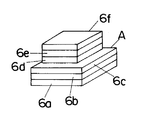
そしてこの操作を必要な層数だけ繰り返すことによって、図2(e)のように所定数の焼結層6a〜6fを積層一体化し、図3のような複数の焼結層6a〜6fからなる金属粉末焼結部品Aを作製することができるものである。
【0005】
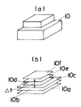
ここで、上記のようにして金属粉末焼結部品Aを作製するにあたっては、図4(a)のような製品10を設計する際の三次元CADデータに基づいて、製品10を図4(b)のように所定の間隔Δtで水平にスライスしたときの各層10a〜10fのスライス面の断面データを得て、このスライス断面データを基にして金属粉末2の各層に照射するレーザビームLの走査経路を決定し、各層10a〜10fに対応する水平断面形状で各焼結層6a〜6fを形成することによって、製品10と同じ三次元形状に金属粉末焼結部品Aを作製することができるものである。そしてこのように各焼結層6a〜6fを順次形成して積み重ねていく工法をとることによって、三次元CADにより設計された形状に従って三次元的に切削加工するCAMを用いるような必要がなくなり、二次元的な加工の繰り返しで三次元的な製品を作製することが可能になるものであり、複雑な機構の装置を用いる必要なく迅速に製作を行なうことができるものである。
【0006】
【特許文献1】
特許第260353号公報
【0007】
【発明が解決しようとする課題】
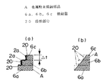
しかし、上記のようにして複数の焼結層6a,6b,6c…を積層一体化して作製される金属粉末焼結部品Aでは、各層の焼結層6a,6b,6c…の端面は垂直面に形成されるために、図1(a)のように金属粉末焼結部品Aの表面をなす焼結層6a,6b,6c…の端縁部は階段状に段差を有するものとして形成されており、しかもこの表面にはレーザビームLによる加熱の余熱によって不要な金属の粉末2aが付着しており、表面の粗度は70〜100μmRyと非常に粗くなっている。
【0008】
しかしながら、金属粉末焼結部品Aを成形金型の部品として使用する場合には、表面粗度は少なくとも7〜10μmRy以下である必要があり、金属粉末焼結部品Aの適用範囲が限られるという問題があった。
【0009】
本発明は上記の点に鑑みてなされたものであり、表面の粗度が小さく表面を滑らかに形成することができる金属粉末焼結部品の表面仕上げ方法を提供することを目的とするものである。
【0010】
【課題を解決するための手段】
本発明に係る金属粉末焼結部品の表面仕上げ方法は、金属粉末2の層の所定箇所にレーザビームLを照射して焼結させることによって焼結層6aを形成し、この焼結層6aの上に金属粉末2の層を被覆すると共にこの金属粉末2の所定箇所にレーザビームLを照射して焼結させることによって下の焼結層6aと一体になった焼結層6bを形成し、これを繰り返すことによって複数の焼結層6a,6b,6c…が積層一体化された金属粉末焼結部品Aを作製するにあたって、金属粉末焼結部品Aの表面と雌雄反転形状の表面を有する電極11を上記金属粉末焼結部品Aの作製法によって表面仕上げ用の加工工具として作製し、上記加工工具を用いて金属粉末焼結部品Aの表面を放電加工することによって金属粉末焼結部品Aの表面をなす各焼結層6a,6b,6c…の端縁の突出する段差部分20を除去することを特徴とするものである。
【0011】
また、金属粉末焼結部品の表面仕上げ方法は、金属粉末2の層の所定箇所にレーザビームLを照射して焼結させることによって焼結層6aを形成し、この焼結層6aの上に金属粉末2の層を被覆すると共にこの金属粉末2の所定箇所にレーザビームLを照射して焼結させることによって下の焼結層6aと一体になった焼結層6bを形成し、これを繰り返すことによって複数の焼結層6a,6b,6c…が積層一体化された金属粉末焼結部品Aを作製するにあたって、金属粉末焼結部品Aの表面と雌雄反転形状の表面を有する研磨具12を上記金属粉末焼結部品Aの作製法によって表面仕上げ用の加工工具として作製し、上記加工工具と金属粉末焼結部品Aとを重ね合わせた状態で振動を与えることによって金属粉末焼結部品Aの表面をなす各焼結層6a,6b,6c…の端縁の突出する段差部分20を除去することを特徴とするものである。
【0012】
そして、加工工具は金属粉末焼結部品Aの表面と雌雄反転形状の表面を有するものであり且つ金属粉末焼結部品Aの製作に用いた三次元CADデータを反転させたデータを基に前記作製法で得たものであることが望ましい。
【0013】
また、金属粉末焼結部品の表面仕上げ方法は、金属粉末2の層の所定箇所にレーザビームLを照射して焼結させることによって焼結層6aを形成し、この焼結層6aの上に金属粉末2の層を被覆すると共にこの金属粉末2の所定箇所にレーザビームLを照射して焼結させることによって下の焼結層6aと一体になった焼結層6bを形成し、これを繰り返すことによって複数の焼結層6a,6b,6c…が積層一体化された金属粉末焼結部品Aを作製するにあたって、金属粉末焼結部品Aの表面と雌雄反転形状の表面を有するものであり且つ金属粉末焼結部品Aの製作に用いた三次元CADデータを反転させたデータを基に前記作製法で得たものを放電加工または機械的研磨による表面仕上げ用の加工工具として、前記金属粉末焼結部品Aの作製法と上記加工工具を用いて金属粉末焼結部品Aの表面をなす各焼結層6a,6b,6c…の端縁の突出する段差部分20を除去することを特徴とするものである。
【0014】
【発明の実施の形態】
以下、本発明の実施の形態を説明する。
【0015】
金属粉末焼結部品Aは既述の図2〜図4のようにして、金属粉末2の層にレーザビームを照射して焼結させることによって焼結層6aを形成し、この焼結層6aの上に金属粉末2の層を被覆すると共にこの金属粉末2にレーザビームLを照射して焼結させることによって下の焼結層6aと一体になった焼結層6bを形成し、そしてこれを繰り返すことによって、複数の焼結層6a,6b,6c…を積層一体化させることによって、作製することができる。ここで、金属粉末2としては例えば粒径20〜30μm程度のブロンズとニッケルの混合粉末を用いることができ、また各焼結層6a,6b,6c…は厚みΔt=0.05〜0.1mm程度に形成することができる。
【0016】
そしてこのように作製した金属粉末焼結部品Aの表面(主として側面)は各焼結層6a,6b,6c…の端縁部で形成されているが、既述の図1(a)のように各焼結層6a,6b,6c…の端縁は階段状の段差を有しており、焼結層6a,6b,6c…の端面の下端とこの焼結層6a,6b,6c…の端縁の露出する上面の基部とを結ぶ面よりも突出するこの段差部分20で金属粉末焼結部品Aの表面には凹凸ができて表面が粗くなっている。
【0017】
そこで、金属粉末焼結部品Aの作製後あるいは、作製プロセス中の半製品の状態で、金属粉末焼結部品Aの表面をなす各焼結層6a,6b,6c…の端縁の段差部分20を図1(b)のように除去することによって、金属粉末焼結部品Aの表面の粗度を小さくして表面を滑らかに形成するようにしている。
【0018】
各焼結層6a,6b,6c…の端縁の段差部分20を除去する表面仕上げ加工手段としては、放電加工や、機械的研磨のためのものを採用することができる。
【0019】
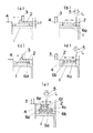
図5は放電加工の場合の一例を示すものであり、金属粉末焼結部品Aの表面に放電加工用の電極11を対向させて配置し、電極11と金属粉末焼結部品Aの間にパルス電圧を印加することによって、金属粉末焼結部品Aの表面をなす各焼結層6a,6b,6c…の端縁の段差部分20をアーク放電で溶融させて除去するようにしたものである。ここで、金属粉末焼結部品Aの表面のうち、各焼結層6a,6b,6c…の端縁の段差部分20は突起となって突出しているので、電極11との距離が最も最短なこの段差部分20からアーク放電が開始され、各焼結層6a,6b,6c…の端縁の段差部分20が優先的に溶融除去されて、金属粉末焼結部品Aの表面の粗度を小さくして表面を滑らかに形成することができるものである。
【0020】
電極11は銅(Cu)や銀タングステン(AgW)などを材料として作製されるが、金属粉末焼結部品Aの三次元表面に全面に亘って同じ距離のギャップ(隙間)で電極11を近接させるように配置して、金属粉末焼結部品Aの表面の全面を均一に放電加工するのが好ましい。このため、金属粉末焼結部品Aの表面と雌雄反転形状に表面を形成するように作製した電極11を用い、金属粉末焼結部品Aの表面に電極11の雌雄反転形状の表面を全面に亘って同じ距離のギャップで近接対向させるようにしてある。このように電極11の表面を金属粉末焼結部品Aの表面と雌雄反転形状に形成するには、既述のように金属粉末焼結部品Aを製作する際に用いた三次元CADデータを反転させ、この反転させたCADデータを使用して切削加工などを行なうことによって、実施することができる。従って電極11を作製するためのCADデータを新たに作成するが必要なくなり、容易に電極11を作製することができるものである。
【0021】
また、電極11として、金属粉末焼結部品Aの表面と電極11の表面との間のギャップが0.2mm程度になるようにした粗加工用電極11と、金属粉末焼結部品Aの表面と電極11の表面との間のギャップが0.05mm程度になるようにした仕上げ加工用電極11と、金属粉末焼結部品Aの表面と電極11の表面との間のギャップがこの中間の中加工用の電極11を用い、まず粗加工用の電極11を用いて放電加工することによって金属粉末焼結部品Aの表面を粗加工し、次に中加工用の電極11を用いて放電加工することによって金属粉末焼結部品Aの表面を中加工し、最後に仕上げ加工用の電極11を用いて放電加工することによって金属粉末焼結部品Aの表面を仕上げ加工するようにするのが好ましい。図6に銅(Cu)や銀タングステン(AgW)で作製した電極11を用いて粗加工、中加工、仕上げ加工したときの金属粉末焼結部品Aの表面粗さを示す。
【0022】
尚、金属粉末焼結部品Aの表面と雌雄反転形状の表面を有する電極11を作製することが困難な場合には、電極11を丸棒や角棒などの単一形状に作製し、NC(数値制御)を有する放電加工機を用いて金属粉末焼結部品Aの表面との間に一定のギャップを確保しながら、この電極11で放電加工を行なうことができる。
【0023】
電極11を上記のように銅や銀タングステンを材料として切削加工等して作製するのではなく、ブロンズとニッケルの混合粉末など金属粉末を用いて金属粉末焼結部品Aを作製する既述の図2〜図4と同じ方法で、電極11を作製したものを用いることができる。
【0024】
すなわち、金属粉末焼結部品Aを作製する際に用いた三次元CADデータを反転させて使用し、この反転させたCADデータに基づいてスライス断面データを得て、このスライス断面データを基にして金属粉末2の各層に照射するレーザビームLの走査経路を決定し、金属粉末焼結部品Aの各焼結層6a,6b,6c…と雌雄反転して対応する断面形状で各焼結層21a,21b,21c…を形成することによって、図7のように金属粉末焼結部品Aの表面と雌雄反転形状の表面を有する電極11を作製することができるものである。このように金属粉末の焼結で電極11を作製することによって、切削加工等で電極11を作製する場合の1/2以下の時間で作製が可能になり、切削加工等では困難な隅部のエッジや微小な凹凸形状、深いリブ溝などの形成も容易に行なうことができるものである。また、電極11を作製するためのCADデータを新たに設計する必要がなくなり、容易に電極11を作製することができるものである。
【0025】
この金属粉末の焼結で作製された電極11は導電性を有するので、上記と同様に金属粉末焼結部品Aの表面にこの電極11を対向させて配置し、電極11と金属粉末焼結部品Aの間にパルス電圧を印加することによって、金属粉末焼結部品Aの表面をなす各焼結層6a,6b,6c…の端縁の段差部分20をアーク放電で溶融させて除去することができるものである。ここで、金属粉末焼結部品Aの表面のうち、各焼結層6a,6b,6c…の端縁の段差部分20は突起となって突出しているので、電極11との距離が最も最短なこの段差部分20からアーク放電が開始され、各焼結層6a,6b,6c…の端縁の段差部分20が優先的に溶融除去されて、金属粉末焼結部品Aの表面の粗度を小さくして表面を滑らかに形成することができるものである。
【0026】
また上記と同様に、電極11として、金属粉末焼結部品Aの表面と電極11の表面との間のギャップが0.2mm程度になるようにした粗加工用電極11と、金属粉末焼結部品Aの表面と電極11の表面との間のギャップが0.05mm程度になるようにした仕上げ加工用電極11と、金属粉末焼結部品Aの表面と電極11の表面との間のギャップがこの中間の中加工用の電極11を用い、まず粗加工用の電極11を用いて放電加工することによって金属粉末焼結部品Aの表面を粗加工し、次に中加工用の電極11を用いて放電加工することによって金属粉末焼結部品Aの表面を中加工し、最後に仕上げ加工用の電極11を用いて放電加工することによって金属粉末焼結部品Aの表面を仕上げ加工するようにするのが好ましい。
【0027】
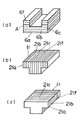
ここで、電極11を上記のように金属粉末の焼結層21a,21b,21c…を一体に積層することによって作製するにあたって、電極11の表面の粗度は焼結層21a,21b,21c…の積層段差があらわれる積層面と垂直な端面が最も粗くなり、金属粉末焼結部品Aに電極11を近接配置して放電加工するにあたって、図10のように金属粉末焼結部品Aの焼結層6a,6b,6c…に対して電極11の焼結層21a,21b,21c…が平行であると、金属粉末焼結品Aの粗な端面に電極11の粗な端面が対向することになり、金属粉末焼結品Aと電極11の間のギャップを均一にすることが難しく、金属粉末焼結部品Aの表面の仕上げ加工精度が悪くなる。従って、金属粉末焼結部品Aが図8(a)のように焼結層6a,6b,6c…を積層して作製されている場合には、図8(b)や図8(c)のように焼結層6a,6b,6c…の積層方向と直交する方向で焼結層21a,21b,21c…を積層して作製した電極11を用い、また金属粉末焼結部品Aが図9(a)のように焼結層6a,6b,6c…を積層して作製されている場合には、図9(b)や図9(c)のように焼結層6a,6b,6c…の積層方向と直交する方向で焼結層21a,21b,21c…を積層して作製した電極11を用いるのが好ましい。
【0028】
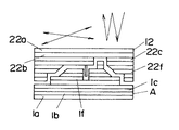
図11は更に他の実施形態の一例を示すものであり、上記の電極11の場合と同様に、金属粉末焼結部品Aを作製する際に用いた三次元CADデータを反転させて使用し、この反転させたCADデータに基づいてスライス断面データを得て、このスライス断面データを基にして金属粉末2の各層に照射するレーザビームLの走査経路を決定し、金属粉末焼結部品Aの各焼結層6a,6b,6c…と雌雄反転して対応する断面形状で焼結層22a,22b,22c…を形成することによって、金属粉末焼結部品Aの表面と雌雄反転形状の表面を有する研磨具12を作製する。従って、研磨具12を作製するためのCADデータを新たに設計する必要がなくなり、容易に研磨具12を作製することができるものである。このとき、金属粉末焼結部品Aに研磨具12をその雌雄反転の表面同士ではめ合わせた際に最小限ギャップが形成されるように研磨具12を作製するものであり、このギャップは金属粉末焼結部品Aや研磨具12の形状精度や表面粗さなどによって異なるが、約0.1〜0.2mm程度が好ましい。
【0029】
そして金属粉末焼結部品Aの表面に研磨具12の雌雄反転形状の表面を重ね、金属粉末焼結部品Aと研磨具12のどちらか一方を固定すると共に他方に図11の矢印のように振動を加え、金属粉末焼結部品Aと研磨具12の表面同士をぶつかり合わせたり擦り合わせたりすることによって、金属粉末焼結部品Aの各焼結層6a,6b,6c…の端縁の突出する段差部分20が潰れて、金属粉末焼結部品Aの表面の粗度を小さくして表面を滑らかに形成することができるものである。このとき与える振動の振動数は、金属粉末焼結部品Aの表面状態や硬度、形状等により異なるが、1500〜25000v.p.m(バイブレーション・パー・ミニッツ)程度が好ましい。また金属粉末焼結部品Aにおいて細リブや微小形状など強度的に非常に弱い部分を持つ場合ほど、高振動・低加重による擦りあわせで研磨を行なうようにするのが好ましい。振動は上下方向及び水平方向への混合された運動で行なうようにしているので、振動モータやバイブレータなどを組み合わせて用いるのがよい。
【0030】
図12は別の実施の形態の一例を示すものであり、図11のものにおいて、金属粉末焼結部品Aと研磨具12の表面の間に研磨砥粒13を入れた状態で振動を加えることによって、金属粉末焼結部品Aの表面の研磨の効率を高めるようにしたものである。研磨砥粒13としては、粒径が金属粉末2の焼結粒子より大きい数μm〜数百μm程度のものを用いるのが好ましい。また金属粉末焼結部品Aと研磨具12の間のギャップが、研磨砥粒13の粒径及びプラスアルファを付加して、約0.2〜0.4mm程度に設定されるように、研磨具12を作製するのが好ましい。また金属粉末焼結部品Aと研磨具12の表面の間に研磨砥粒13を入れた状態で振動を加えて研磨を行なうにあたって、研磨砥粒13が金属粉末焼結部品Aと研磨具12の間から洩れるのを防ぐために、金属粉末焼結部品Aと研磨具12の間の隙間を外周からテープで塞ぐようにするのが好ましい。
【0031】
そして金属粉末焼結部品Aと研磨具12のどちらか一方を固定すると共に他方に図12の矢印のように振動を加え、研磨砥粒13で金属粉末焼結部品Aの各焼結層6a,6b,6c…の端縁の突出する段差部分20を摩滅させ、金属粉末焼結部品Aの表面の粗度を小さくして表面を滑らかに形成することができるものである。このとき与える振動の振動数は、金属粉末焼結部品Aの表面状態や硬度、形状等により異なるが、1500〜25000v.p.m程度が好ましい。また金属粉末焼結部品Aにおいて細リブや微小形状など強度的に非常に弱い部分を持つ場合ほど、高振動・低加重による擦りあわせで研磨を行なうようにするのが好ましい。振動は上下方向及び水平方向への混合された運動で行なうようにしているので、振動モータやバイブレータなどを組み合わせて用いるのがよい。
【0032】
尚、本発明において、金属粉末焼結部品Aの各焼結層1a,1b,1c…の端縁の表面仕上げを行なうだけでなく、金属粉末焼結部品Aの底面や上面についても表面仕上げを行なうことができるものである。
【0033】
【発明の効果】
上記のように本発明は、金属粉末の層の所定箇所にレーザビームを照射して焼結させることによって焼結層を形成し、この焼結層の上に金属粉末の層を被覆すると共にこの金属粉末の所定箇所にレーザビームを照射して焼結させることによって下の焼結層と一体になった焼結層を形成し、これを繰り返すことによって複数の焼結層が積層一体化された金属粉末焼結部品を作製するにあたって、上記金属粉末焼結部品の作製法と同法にて得た表面仕上げ用の加工工具を用いて金属粉末焼結部品の表面をなす各焼結層の端縁の突出する段差部分を除去するようにしたので、金属粉末焼結部品の表面の粗度を小さくすることができ、金属粉末焼結部品の表面を滑らかに形成することができるものである。しかも加工工具は金属粉末焼結部品の作製法と同法にて得たものであるために、金属粉末焼結部品を作製する際に使用した三次元CADデータを用いて加工工具を作製することが可能になり、加工工具の設計が不要になると共に金属粉末焼結部品を作製する装置をそのまま用いて加工工具を作製することができる。
【0034】
この時、加工工具としては、金属粉末焼結部品の表面と雌雄反転形状の表面を有する放電加工用電極や、研磨具を用いることができ、前者であれば、放電加工で金属粉末焼結部品の表面の粗度を小さくして金属粉末焼結部品の表面を滑らかに形成することができ、後者であれば、金属粉末焼結部品と研磨具の表面同士のぶつかり合いや擦り合わせで研磨を行なうことができ、金属粉末焼結部品の表面の粗度を小さくして、金属粉末焼結部品の表面を滑らかに形成することができる。
【0035】
また金属粉末焼結部品と研磨具との間に研磨砥粒を入れて振動を与えるようにすれば、研磨砥粒の作用で効率良く研磨をすることができ、金属粉末焼結部品の表面の粗度を小さくして、金属粉末焼結部品の表面を滑らかに形成することができる。
【0036】
そして上記加工工具が金属粉末焼結部品の表面と雌雄反転形状の表面を有するものであり且つ金属粉末焼結部品の製作に用いた三次元CADデータを反転させたデータを基に前記作製法で得たものであれば、前述のように加工工具の設計が不要になると共に金属粉末焼結部品を作製する装置をそのまま用いて加工工具を作製することができる。
【図面の簡単な説明】
【図1】 本発明の実施の形態における一例での仕上げ加工の前後を示すものであり、(a)は仕上げ加工前の金属粉末焼結部品の一部の拡大した断面図、(b)は仕上げ加工後の金属粉末焼結部品の一部の拡大した断面図である。
【図2】 本発明の実施の形態における一例での金属粉末焼結部品の製造の各工程を示すものであり、(a)乃至(e)はそれぞれ断面図である。
【図3】 同上によって製造された金属粉末焼結部品の斜視図である。
【図4】 (a)は設計された製品を示す斜視図、(b)は製品をスライスした各層を示す斜視図である。
【図5】 本発明の実施の形態の一例を示す正面図である。
【図6】 同上の実施の形態での放電加工と表面粗さの関係を示すグラフである。
【図7】 本発明の実施の形態の一例を示す正面図である。
【図8】 同上の実施の形態の一例を示すものであり(a)は金属粉末焼結部品の斜視図、(b)は電極の斜視図、(c)は電極の斜視図である。
【図9】 同上の実施の形態の一例を示すものであり(a)は金属粉末焼結部品の斜視図、(b)は電極の斜視図、(c)は電極の斜視図である。
【図10】 同上の実施の形態の一例における問題点を示す金属粉末焼結部品と電極の一部の断面図である。
【図11】 本発明の実施の形態の一例を示す正面図である。
【図12】 本発明の実施の形態の一例を示す正面図である。
【符号の説明】
2 金属粉末
6a,6b,6c 焼結層
11 電極
12 研磨具
13 研磨砥粒
20 段差部分[0001]
BACKGROUND OF THE INVENTION
The present invention relates to a method for finishing a surface of a sintered metal powder part produced by laminating and integrating a plurality of sintered layers of sintered metal powder using a laser beam.
[0002]
[Prior art]
A sintered layer is formed by irradiating a laser beam onto a metal powder layer to sinter the metal powder layer, and coating the metal powder layer on the sintered layer and irradiating the metal powder with a laser beam for sintering. For example, a method for producing a sintered metal powder part in which a plurality of sintered layers are laminated and integrated by forming a sintered layer integrated with a lower sintered layer by repeating the process is disclosed in, for example, a patent. No. 260353 and the like.
[0003]
FIG. 2 shows an example. First, as shown in FIG. 2A, the
[0004]
Then, by repeating this operation for the required number of layers, a predetermined number of sintered
[0005]
Here, in producing the metal powder sintered part A as described above, the
[0006]
[Patent Document 1]
Japanese Patent No. 260353
[Problems to be solved by the invention]
However, in the metal powder sintered part A produced by laminating and integrating the plurality of sintered
[0008]
However, when the metal powder sintered part A is used as a part of a molding die, the surface roughness needs to be at least 7 to 10 μm Ry, and the application range of the metal powder sintered part A is limited. was there.
[0009]
The present invention has been made in view of the above points, and it is an object of the present invention to provide a surface finishing method for metal powder sintered parts which can form a smooth surface with a small surface roughness. .
[0010]
[Means for Solving the Problems]
The surface finishing method of the metal powder sintered part according to the present invention forms a sintered
[0011]
Further, the surface finishing method of the metal powder sintered part is to form a sintered
[0012]
And the processing tool has the surface of the metal powder sintered part A and the surface of the male and female reversal shape, and the production is based on the data obtained by reversing the three-dimensional CAD data used for the production of the metal powder sintered part A. It is desirable that it is obtained by law.
[0013]
Further, the surface finishing method of the metal powder sintered part is to form a sintered
[0014]
DETAILED DESCRIPTION OF THE INVENTION
Embodiments of the present invention will be described below.
[0015]
2 to 4, the metal powder sintered part A forms a
[0016]
The surface (mainly the side surface) of the metal powder sintered part A produced in this way is formed by the edge portions of the respective
[0017]
Therefore , the stepped
[0018]
As the surface finishing processing means for removing the stepped
[0019]
FIG. 5 shows an example in the case of electric discharge machining. An electrode 11 for electric discharge machining is arranged opposite to the surface of the metal powder sintered part A, and a pulse is formed between the electrode 11 and the metal powder sintered part A. By applying a voltage, the stepped
[0020]
The electrode 11 is manufactured using copper (Cu), silver tungsten (AgW), or the like as a material. The electrode 11 is brought close to the three-dimensional surface of the metal powder sintered part A with a gap of the same distance over the entire surface. It is preferable that the entire surface of the metal powder sintered part A is uniformly subjected to electric discharge machining. For this reason, the surface of the metal powder sintered part A and the electrode 11 produced so as to form a surface in a male and female inverted shape are used, and the surface of the metal powder sintered part A is covered with the surface of the male and female inverted shape over the entire surface. In close proximity to each other with a gap of the same distance. In this way, in order to form the surface of the electrode 11 in a reversal shape with the surface of the metal powder sintered part A, the three-dimensional CAD data used when manufacturing the metal powder sintered part A as described above is inverted. It can be carried out by performing cutting using the inverted CAD data. Accordingly, it is not necessary to newly create CAD data for manufacturing the electrode 11, and the electrode 11 can be easily manufactured.
[0021]
Further, as the electrode 11, a rough machining electrode 11 in which the gap between the surface of the metal powder sintered part A and the surface of the electrode 11 is about 0.2 mm, and the surface of the metal powder sintered part A; The finish processing electrode 11 having a gap between the surface of the electrode 11 of about 0.05 mm and the gap between the surface of the metal powder sintered part A and the surface of the electrode 11 is intermediate processing. First, the surface of the metal powder sintered part A is rough processed by electric discharge machining using the electrode 11 for rough machining, and then electric discharge machining is performed using the electrode 11 for medium machining. It is preferable to finish the surface of the metal powder sintered part A by subjecting the surface of the metal powder sintered part A to intermediate machining, and finally performing electric discharge machining using the electrode 11 for finishing. FIG. 6 shows the surface roughness of the sintered metal powder part A when roughing, intermediate working, and finishing using the electrode 11 made of copper (Cu) or silver tungsten (AgW).
[0022]
In addition, when it is difficult to produce the electrode 11 having the surface of the metal powder sintered part A and the surface of the male and female inverted shapes, the electrode 11 is produced in a single shape such as a round bar or a square bar, and NC ( This electrode 11 can be used for electric discharge machining while ensuring a certain gap with the surface of the metal powder sintered part A using an electric discharge machine having numerical control.
[0023]
As described above, the electrode 11 is not manufactured by cutting using copper or silver tungsten as a material, but the metal powder sintered part A is manufactured using a metal powder such as a mixed powder of bronze and nickel. 2 to 4 can be used in the same manner as in FIG .
[0024]
In other words, the three-dimensional CAD data used in producing the metal powder sintered part A is inverted and used, slice slice data is obtained based on the inverted CAD data, and the slice slice data is used as a basis. The scanning path of the laser beam L irradiating each layer of the
[0025]
Since the electrode 11 produced by sintering the metal powder has conductivity, the electrode 11 is disposed on the surface of the metal powder sintered part A in the same manner as described above, and the electrode 11 and the metal powder sintered part are arranged. By applying a pulse voltage between A, the stepped
[0026]
Similarly to the above, as the electrode 11, the rough machining electrode 11 in which the gap between the surface of the metal powder sintered part A and the surface of the electrode 11 is about 0.2 mm, and the metal powder sintered part The gap between the surface of A and the surface of the electrode 11 is about 0.05 mm, and the gap between the surface of the metal powder sintered part A and the surface of the electrode 11 is this. First, the surface of the metal powder sintered part A is rough processed by electric discharge machining using the intermediate machining electrode 11 and then the rough machining electrode 11, and then the middle machining electrode 11 is used. The surface of the metal powder sintered part A is subjected to medium machining by electric discharge machining, and finally the surface of the metal powder sintered part A is finished by electric discharge machining using the electrode 11 for finishing machining. Is preferred.
[0027]
Here, when the electrode 11 is manufactured by integrally laminating the
[0028]
FIG. 11 shows an example of still another embodiment . Similar to the case of the electrode 11 described above, the three-dimensional CAD data used in producing the metal powder sintered part A is inverted and used. Based on the inverted CAD data, slice cross-section data is obtained, and based on the slice cross-section data, the scanning path of the laser beam L irradiated to each layer of the
[0029]
Then, the surface of the metal powder sintered part A is overlapped with the surface of the polishing
[0030]
FIG. 12 shows an example of another embodiment . In FIG. 11 , the vibration is applied with the
[0031]
Then, either one of the metal powder sintered part A and the polishing
[0032]
In the present invention, not only the surface finishing of the edges of the sintered layers 1a, 1b, 1c... Of the metal powder sintered part A but also the surface finishing of the bottom and top surfaces of the metal powder sintered part A is performed. It can be done.
[0033]
【The invention's effect】
As described above, the present invention forms a sintered layer by irradiating a predetermined portion of the metal powder layer with a laser beam and sintering it, and coats the metal powder layer on the sintered layer. By irradiating a predetermined portion of the metal powder with a laser beam and sintering, a sintered layer integrated with the lower sintered layer is formed, and by repeating this, a plurality of sintered layers are laminated and integrated. When producing a metal powder sintered part, the edge of each sintered layer forming the surface of the metal powder sintered part using the surface finishing processing tool obtained by the same method as the above metal powder sintered part production method. Since the stepped portion protruding from the edge is removed, the surface roughness of the metal powder sintered part can be reduced, and the surface of the metal powder sintered part can be formed smoothly. Moreover, since the machining tool is obtained by the same method as the method for producing the metal powder sintered part, the machining tool is produced using the three-dimensional CAD data used when producing the metal powder sintered part. Thus, the design of the processing tool is not required, and the processing tool can be manufactured using the apparatus for manufacturing the sintered metal powder part as it is.
[0034]
At this time, as a processing tool, an electrode for electric discharge machining having a surface of a metal powder sintered part and a surface of a male and female reversal shape, or a polishing tool can be used. The surface of the metal powder sintered part can be formed smoothly by reducing the roughness of the surface of the metal powder. In the latter case, the metal powder sintered part and the surface of the polishing tool can be ground or rubbed together. The roughness of the surface of the metal powder sintered part can be reduced, and the surface of the metal powder sintered part can be formed smoothly.
[0035]
Moreover, if abrasive grains are put between the metal powder sintered part and the polishing tool so as to give vibration, polishing can be efficiently performed by the action of the abrasive grains, and the surface of the metal powder sintered part can be polished. The surface of the metal powder sintered part can be smoothly formed by reducing the roughness.
[0036]
The above processing tool has a surface of a metal powder sintered part and a surface of a male and female reversal shape and is based on the data obtained by reversing the three-dimensional CAD data used for the production of the metal powder sintered part. If it is obtained, the design of the machining tool becomes unnecessary as described above, and the machining tool can be produced using the apparatus for producing the metal powder sintered part as it is.
[Brief description of the drawings]
FIG. 1 shows before and after finishing in an example of an embodiment of the present invention, (a) is an enlarged sectional view of a part of a sintered metal powder part before finishing, and (b) is It is sectional drawing to which some metal powder sintered parts after finishing were expanded.
FIGS. 2A to 2E show steps of manufacturing a metal powder sintered part as an example in the embodiment of the present invention, and FIGS.
FIG. 3 is a perspective view of a sintered metal powder part manufactured by the same as above.
4A is a perspective view showing a designed product, and FIG. 4B is a perspective view showing each layer obtained by slicing the product.
FIG. 5 is a front view showing an example of an embodiment of the present invention.
FIG. 6 is a graph showing the relationship between electric discharge machining and surface roughness in the embodiment.
FIG. 7 is a front view showing an example of an embodiment of the present invention.
FIGS. 8A and 8B show an example of the above embodiment, wherein FIG. 8A is a perspective view of a metal powder sintered part, FIG. 8B is a perspective view of an electrode, and FIG. 8C is a perspective view of the electrode.
FIGS. 9A and 9B show an example of the above embodiment, wherein FIG. 9A is a perspective view of a sintered metal powder component, FIG. 9B is a perspective view of an electrode, and FIG. 9C is a perspective view of the electrode.
FIG. 10 is a cross-sectional view of a part of a metal powder sintered component and an electrode showing problems in an example of the embodiment described above.
FIG. 11 is a front view showing an example of an embodiment of the present invention.
FIG. 12 is a front view showing an example of an embodiment of the present invention.
[Explanation of symbols]
2
Claims (5)
上記金属粉末焼結部品の表面と雌雄反転形状の表面を有する電極を上記金属粉末焼結部品の作製法によって表面仕上げ用の加工工具として作製し、
上記加工工具を用いて金属粉末焼結部品の表面を放電加工することによって金属粉末焼結部品の表面をなす各焼結層の端縁の突出する段差部分の除去を行うことを特徴とする金属粉末焼結部品の表面仕上げ方法。A sintered layer is formed by irradiating a predetermined portion of the metal powder layer with a laser beam to sinter, and a metal powder layer is coated on the sintered layer, and a laser beam is applied to the predetermined portion of the metal powder. To form a sintered layer that is integrated with the underlying sintered layer, and by repeating this process, a metal powder sintered part in which a plurality of sintered layers are laminated and integrated is manufactured. Before
An electrode having a surface of the metal powder sintered part and a male and female reversal shaped surface is produced as a processing tool for surface finishing by the method of producing the metal powder sintered part,
A metal characterized in that the stepped portion protruding from the edge of each sintered layer forming the surface of the metal powder sintered part is removed by electric discharge machining of the surface of the metal powder sintered part using the above processing tool Surface finishing method for powder sintered parts.
上記金属粉末焼結部品の表面と雌雄反転形状の表面を有する研磨具を上記金属粉末焼結部品の作製法によって表面仕上げ用の加工工具として作製し、
上記加工工具と金属粉末焼結部品とを重ね合わせた状態で振動を与えることによって金属粉末焼結部品の表面をなす各焼結層の端縁の突出する段差部分の除去を行うことを特徴とする金属粉末焼結部品の表面仕上げ方法。 A sintered layer is formed by irradiating a predetermined portion of the metal powder layer with a laser beam to sinter, and a metal powder layer is coated on the sintered layer, and a laser beam is applied to the predetermined portion of the metal powder. To form a sintered layer that is integrated with the underlying sintered layer, and by repeating this process, a metal powder sintered part in which a plurality of sintered layers are laminated and integrated is manufactured. Before
A polishing tool having a surface of the metal powder sintered part and a surface of a male and female inverted shape is produced as a processing tool for surface finishing by the method of producing the metal powder sintered part,
It is characterized in that the stepped portion protruding from the edge of each sintered layer forming the surface of the metal powder sintered part is removed by applying vibration in a state where the processing tool and the metal powder sintered part are overlaid. to Rukin genus surface finishing method of a powder sintered parts.
上記金属粉末焼結部品の表面と雌雄反転形状の表面を有するものであり且つ金属粉末焼結部品の製作に用いた三次元CADデータを反転させたデータを基に上記金属粉末焼結部品の作製法によって作製したものを放電加工または機械的研磨による表面仕上げ用の加工工具として、
前記金属粉末焼結部品の作製法と上記加工工具を用いて金属粉末焼結部品の表面をなす各焼結層の端縁の突出する段差部分の除去を行うことを特徴とする金属粉末焼結部品の表面仕上げ方法。 A sintered layer is formed by irradiating a predetermined portion of the metal powder layer with a laser beam to sinter, and a metal powder layer is coated on the sintered layer, and a laser beam is applied to the predetermined portion of the metal powder. To form a sintered layer that is integrated with the underlying sintered layer, and by repeating this process, a metal powder sintered part in which a plurality of sintered layers are laminated and integrated is manufactured. Before
Production of the sintered metal powder part based on the data obtained by reversing the three-dimensional CAD data used for the production of the sintered metal powder part, which has the surface of the sintered metal powder part and the surface of the inverted male and female parts. As a processing tool for surface finishing by electrical discharge machining or mechanical polishing,
Metallic powder sintered, characterized in that the removal of the edge protruding step portion of the sintered layer forming the surface of the metal powder sintered component using the manufacturing method and the machining tool of the metal powder sintered component Surface finishing method for bonded parts.
Priority Applications (1)
| Application Number | Priority Date | Filing Date | Title |
|---|---|---|---|
| JP2003096840A JP4239652B2 (en) | 2003-03-31 | 2003-03-31 | Surface finishing method for metal powder sintered parts |
Applications Claiming Priority (1)
| Application Number | Priority Date | Filing Date | Title |
|---|---|---|---|
| JP2003096840A JP4239652B2 (en) | 2003-03-31 | 2003-03-31 | Surface finishing method for metal powder sintered parts |
Related Parent Applications (1)
| Application Number | Title | Priority Date | Filing Date |
|---|---|---|---|
| JP24058898A Division JP3446618B2 (en) | 1998-08-26 | 1998-08-26 | Surface finishing method for metal powder sintered parts |
Publications (3)
| Publication Number | Publication Date |
|---|---|
| JP2003293012A JP2003293012A (en) | 2003-10-15 |
| JP2003293012A5 JP2003293012A5 (en) | 2005-10-27 |
| JP4239652B2 true JP4239652B2 (en) | 2009-03-18 |
Family
ID=29244530
Family Applications (1)
| Application Number | Title | Priority Date | Filing Date |
|---|---|---|---|
| JP2003096840A Expired - Lifetime JP4239652B2 (en) | 2003-03-31 | 2003-03-31 | Surface finishing method for metal powder sintered parts |
Country Status (1)
| Country | Link |
|---|---|
| JP (1) | JP4239652B2 (en) |
Cited By (2)
| Publication number | Priority date | Publication date | Assignee | Title |
|---|---|---|---|---|
| WO2020245709A1 (en) * | 2019-06-07 | 2020-12-10 | 3M Innovative Properties Company | Method of finishing a metallic surface |
| US11123924B2 (en) | 2017-02-21 | 2021-09-21 | Renishaw Plc | Powder bed fusion apparatus and methods |
Families Citing this family (14)
| Publication number | Priority date | Publication date | Assignee | Title |
|---|---|---|---|---|
| US7537664B2 (en) | 2002-11-08 | 2009-05-26 | Howmedica Osteonics Corp. | Laser-produced porous surface |
| US20060147332A1 (en) | 2004-12-30 | 2006-07-06 | Howmedica Osteonics Corp. | Laser-produced porous structure |
| JP2006247989A (en) * | 2005-03-10 | 2006-09-21 | Roland Dg Corp | 3D modeling method and 3D modeling apparatus |
| US8728387B2 (en) | 2005-12-06 | 2014-05-20 | Howmedica Osteonics Corp. | Laser-produced porous surface |
| DE102006033047A1 (en) * | 2006-07-14 | 2008-01-24 | Viktor Georgiev | Device for masking surface areas that should not be treated with surface changing treatment of work pieces, has coverings that consist of same physical and chemical characteristics as the surface areas of the work pieces not to be treated |
| US10000021B2 (en) | 2009-06-23 | 2018-06-19 | Panasonic Intellectual Property Management Co., Ltd. | Method for manufacturing three-dimensional shaped object and three-dimensional shaped object obtained by the same |
| JP5991574B2 (en) * | 2012-03-16 | 2016-09-14 | パナソニックIpマネジメント株式会社 | Manufacturing method of three-dimensional shaped object |
| US9180010B2 (en) | 2012-04-06 | 2015-11-10 | Howmedica Osteonics Corp. | Surface modified unit cell lattice structures for optimized secure freeform fabrication |
| US9135374B2 (en) | 2012-04-06 | 2015-09-15 | Howmedica Osteonics Corp. | Surface modified unit cell lattice structures for optimized secure freeform fabrication |
| JP6276091B2 (en) * | 2014-03-31 | 2018-02-07 | 日本電子株式会社 | Blasting device used in 3D additive manufacturing equipment |
| KR102118312B1 (en) * | 2015-06-25 | 2020-06-03 | 파나소닉 아이피 매니지먼트 가부시키가이샤 | Manufacturing method of three-dimensional shape sculpture |
| US11298747B2 (en) | 2017-05-18 | 2022-04-12 | Howmedica Osteonics Corp. | High fatigue strength porous structure |
| JP7020843B2 (en) | 2017-09-29 | 2022-02-16 | 株式会社ミマキエンジニアリング | Modeling method and modeling equipment |
| DE102024203447B3 (en) * | 2024-04-15 | 2025-08-07 | Universität Stuttgart, Körperschaft Des Öffentlichen Rechts | Method for producing a component by means of an additive manufacturing process using an energy beam |
Family Cites Families (5)
| Publication number | Priority date | Publication date | Assignee | Title |
|---|---|---|---|---|
| HUT56018A (en) * | 1986-10-17 | 1991-07-29 | Univ Texas | Method and apparatus for producing workpieces by selective sintering |
| JPH0196353A (en) * | 1987-10-08 | 1989-04-14 | Kobe Steel Ltd | Material for electric discharge machining and its manufacture |
| AU643700B2 (en) * | 1989-09-05 | 1993-11-25 | University Of Texas System, The | Multiple material systems and assisted powder handling for selective beam sintering |
| JP3366512B2 (en) * | 1995-10-17 | 2003-01-14 | ローランドディー.ジー.株式会社 | 3D modeling method |
| AU1210297A (en) * | 1995-12-31 | 1997-07-28 | Shinko Sellbic Co., Ltd. | Moldless molding method using no mold and apparatus therefor |
-
2003
- 2003-03-31 JP JP2003096840A patent/JP4239652B2/en not_active Expired - Lifetime
Cited By (3)
| Publication number | Priority date | Publication date | Assignee | Title |
|---|---|---|---|---|
| US11123924B2 (en) | 2017-02-21 | 2021-09-21 | Renishaw Plc | Powder bed fusion apparatus and methods |
| US11691342B2 (en) | 2017-02-21 | 2023-07-04 | Renishaw Plc | Powder bed fusion apparatus and methods |
| WO2020245709A1 (en) * | 2019-06-07 | 2020-12-10 | 3M Innovative Properties Company | Method of finishing a metallic surface |
Also Published As
| Publication number | Publication date |
|---|---|
| JP2003293012A (en) | 2003-10-15 |
Similar Documents
| Publication | Publication Date | Title |
|---|---|---|
| JP3446618B2 (en) | Surface finishing method for metal powder sintered parts | |
| JP4239652B2 (en) | Surface finishing method for metal powder sintered parts | |
| JP6621072B2 (en) | Manufacturing method of three-dimensional shaped object | |
| CN103561891B (en) | Method for manufacturing three-dimensional shaped object | |
| JP6643631B2 (en) | Manufacturing method of three-dimensional shaped object | |
| KR20030077933A (en) | Method of making sintered object | |
| JP4874133B2 (en) | Mold and manufacturing method thereof | |
| JP2008291315A (en) | Manufacturing method of three-dimensional shaped object | |
| JP2002066844A (en) | Method of manufacturing discharge machining electrode using metal powder sintering type laminated molding | |
| JP4452692B2 (en) | Surface finishing method for 3D additive manufacturing parts | |
| Tay et al. | The potential of plating techniques in the development of rapid EDM tooling | |
| CN114555348A (en) | Extrusion die and method for producing an extrusion die | |
| JP5454076B2 (en) | Manufacturing method of shaped objects | |
| JP2024508919A (en) | Removal of support structures with a laser beam integrated into the robot arm | |
| JP2017074594A (en) | Manufacturing method for micro press die and manufacturing method for micro product | |
| KR102245111B1 (en) | Method for manufacturing magnetic core | |
| JP2011110605A (en) | Roll forming apparatus of porous metal foil | |
| JP5589116B2 (en) | Perforated metal foil roll forming equipment | |
| KR100483681B1 (en) | a manufacturing process for a material of diamond cutter | |
| KR20180024021A (en) | Improved sputtering coil product and manufacturing method | |
| JP2750965B2 (en) | Manufacturing method of contact having contact part with precision step surface | |
| JP2005014558A (en) | Manufacturing method of laminated mold | |
| JP2003311605A (en) | Abrasive embedding apparatus and method, and polishing apparatus using the same | |
| JP2002126952A (en) | Method of manufacturing abrasion resistant part | |
| JP5261015B2 (en) | Resin mold and method for producing resin mold |
Legal Events
| Date | Code | Title | Description |
|---|---|---|---|
| A621 | Written request for application examination |
Free format text: JAPANESE INTERMEDIATE CODE: A621 Effective date: 20050706 |
|
| A521 | Request for written amendment filed |
Free format text: JAPANESE INTERMEDIATE CODE: A523 Effective date: 20050712 |
|
| A131 | Notification of reasons for refusal |
Free format text: JAPANESE INTERMEDIATE CODE: A131 Effective date: 20080916 |
|
| A521 | Request for written amendment filed |
Free format text: JAPANESE INTERMEDIATE CODE: A523 Effective date: 20081104 |
|
| TRDD | Decision of grant or rejection written | ||
| A01 | Written decision to grant a patent or to grant a registration (utility model) |
Free format text: JAPANESE INTERMEDIATE CODE: A01 Effective date: 20081202 |
|
| A01 | Written decision to grant a patent or to grant a registration (utility model) |
Free format text: JAPANESE INTERMEDIATE CODE: A01 |
|
| A61 | First payment of annual fees (during grant procedure) |
Free format text: JAPANESE INTERMEDIATE CODE: A61 Effective date: 20081215 |
|
| FPAY | Renewal fee payment (event date is renewal date of database) |
Free format text: PAYMENT UNTIL: 20120109 Year of fee payment: 3 |
|
| FPAY | Renewal fee payment (event date is renewal date of database) |
Free format text: PAYMENT UNTIL: 20120109 Year of fee payment: 3 |
|
| FPAY | Renewal fee payment (event date is renewal date of database) |
Free format text: PAYMENT UNTIL: 20120109 Year of fee payment: 3 |
|
| FPAY | Renewal fee payment (event date is renewal date of database) |
Free format text: PAYMENT UNTIL: 20130109 Year of fee payment: 4 |
|
| FPAY | Renewal fee payment (event date is renewal date of database) |
Free format text: PAYMENT UNTIL: 20130109 Year of fee payment: 4 |
|
| EXPY | Cancellation because of completion of term |