JP4237962B2 - Method for treating solid waste containing organic matter - Google Patents
Method for treating solid waste containing organic matter Download PDFInfo
- Publication number
- JP4237962B2 JP4237962B2 JP2001564900A JP2001564900A JP4237962B2 JP 4237962 B2 JP4237962 B2 JP 4237962B2 JP 2001564900 A JP2001564900 A JP 2001564900A JP 2001564900 A JP2001564900 A JP 2001564900A JP 4237962 B2 JP4237962 B2 JP 4237962B2
- Authority
- JP
- Japan
- Prior art keywords
- fraction
- slurry
- waste
- sand
- sieving
- Prior art date
- Legal status (The legal status is an assumption and is not a legal conclusion. Google has not performed a legal analysis and makes no representation as to the accuracy of the status listed.)
- Expired - Lifetime
Links
- 238000000034 method Methods 0.000 title claims description 60
- 239000002910 solid waste Substances 0.000 title claims description 10
- 239000005416 organic matter Substances 0.000 title claims description 7
- 239000002002 slurry Substances 0.000 claims description 80
- XLYOFNOQVPJJNP-UHFFFAOYSA-N water Substances O XLYOFNOQVPJJNP-UHFFFAOYSA-N 0.000 claims description 56
- 239000004576 sand Substances 0.000 claims description 54
- 239000002699 waste material Substances 0.000 claims description 49
- 238000007873 sieving Methods 0.000 claims description 47
- 229910052751 metal Inorganic materials 0.000 claims description 40
- 239000002184 metal Substances 0.000 claims description 40
- 239000000835 fiber Substances 0.000 claims description 30
- CWYNVVGOOAEACU-UHFFFAOYSA-N Fe2+ Chemical compound [Fe+2] CWYNVVGOOAEACU-UHFFFAOYSA-N 0.000 claims description 29
- 238000000855 fermentation Methods 0.000 claims description 22
- 238000009264 composting Methods 0.000 claims description 21
- 238000000926 separation method Methods 0.000 claims description 20
- 239000010791 domestic waste Substances 0.000 claims description 16
- 230000004151 fermentation Effects 0.000 claims description 16
- XEEYBQQBJWHFJM-UHFFFAOYSA-N Iron Chemical compound [Fe] XEEYBQQBJWHFJM-UHFFFAOYSA-N 0.000 claims description 15
- 230000018044 dehydration Effects 0.000 claims description 15
- 238000006297 dehydration reaction Methods 0.000 claims description 15
- 239000000126 substance Substances 0.000 claims description 11
- 239000002245 particle Substances 0.000 claims description 10
- 239000002738 chelating agent Substances 0.000 claims description 9
- 238000010790 dilution Methods 0.000 claims description 7
- 239000012895 dilution Substances 0.000 claims description 7
- 238000007865 diluting Methods 0.000 claims description 6
- 238000006460 hydrolysis reaction Methods 0.000 claims description 6
- 230000007062 hydrolysis Effects 0.000 claims description 5
- 239000002440 industrial waste Substances 0.000 claims description 3
- 238000002156 mixing Methods 0.000 claims description 3
- 230000031018 biological processes and functions Effects 0.000 claims 1
- 239000006185 dispersion Substances 0.000 claims 1
- 229910001385 heavy metal Inorganic materials 0.000 description 18
- 239000002361 compost Substances 0.000 description 11
- 239000000463 material Substances 0.000 description 9
- 229920002994 synthetic fiber Polymers 0.000 description 8
- 239000007787 solid Substances 0.000 description 7
- 238000005273 aeration Methods 0.000 description 6
- 238000012216 screening Methods 0.000 description 6
- 238000004062 sedimentation Methods 0.000 description 5
- 238000010586 diagram Methods 0.000 description 4
- -1 ferrous metals Chemical class 0.000 description 4
- 238000004064 recycling Methods 0.000 description 4
- 239000002351 wastewater Substances 0.000 description 4
- 239000007864 aqueous solution Substances 0.000 description 3
- 239000000356 contaminant Substances 0.000 description 3
- 239000012467 final product Substances 0.000 description 3
- 238000005188 flotation Methods 0.000 description 3
- 150000002739 metals Chemical class 0.000 description 3
- 239000010812 mixed waste Substances 0.000 description 3
- 230000003647 oxidation Effects 0.000 description 3
- 238000007254 oxidation reaction Methods 0.000 description 3
- 238000012545 processing Methods 0.000 description 3
- 230000008929 regeneration Effects 0.000 description 3
- 238000011069 regeneration method Methods 0.000 description 3
- 239000011343 solid material Substances 0.000 description 3
- IJGRMHOSHXDMSA-UHFFFAOYSA-N Atomic nitrogen Chemical compound N#N IJGRMHOSHXDMSA-UHFFFAOYSA-N 0.000 description 2
- 239000013505 freshwater Substances 0.000 description 2
- 239000011521 glass Substances 0.000 description 2
- 239000010813 municipal solid waste Substances 0.000 description 2
- 239000000047 product Substances 0.000 description 2
- 238000000746 purification Methods 0.000 description 2
- 239000013049 sediment Substances 0.000 description 2
- 239000004575 stone Substances 0.000 description 2
- 238000009423 ventilation Methods 0.000 description 2
- 238000013022 venting Methods 0.000 description 2
- 238000005054 agglomeration Methods 0.000 description 1
- 230000002776 aggregation Effects 0.000 description 1
- 238000013019 agitation Methods 0.000 description 1
- 230000009286 beneficial effect Effects 0.000 description 1
- 238000006065 biodegradation reaction Methods 0.000 description 1
- 230000004071 biological effect Effects 0.000 description 1
- 229910010293 ceramic material Inorganic materials 0.000 description 1
- 238000011109 contamination Methods 0.000 description 1
- 230000006837 decompression Effects 0.000 description 1
- 235000014113 dietary fatty acids Nutrition 0.000 description 1
- 239000003344 environmental pollutant Substances 0.000 description 1
- 239000002360 explosive Substances 0.000 description 1
- 229930195729 fatty acid Natural products 0.000 description 1
- 239000000194 fatty acid Substances 0.000 description 1
- 150000004665 fatty acids Chemical class 0.000 description 1
- 239000002657 fibrous material Substances 0.000 description 1
- 230000005484 gravity Effects 0.000 description 1
- 238000007885 magnetic separation Methods 0.000 description 1
- 239000007769 metal material Substances 0.000 description 1
- 230000004048 modification Effects 0.000 description 1
- 238000012986 modification Methods 0.000 description 1
- 229910052757 nitrogen Inorganic materials 0.000 description 1
- 239000010815 organic waste Substances 0.000 description 1
- 239000007800 oxidant agent Substances 0.000 description 1
- 231100000719 pollutant Toxicity 0.000 description 1
- 238000001556 precipitation Methods 0.000 description 1
- 238000004537 pulping Methods 0.000 description 1
- 239000008213 purified water Substances 0.000 description 1
- 230000003134 recirculating effect Effects 0.000 description 1
- 239000010819 recyclable waste Substances 0.000 description 1
- 230000000717 retained effect Effects 0.000 description 1
- 238000005549 size reduction Methods 0.000 description 1
- 239000000758 substrate Substances 0.000 description 1
- 238000011144 upstream manufacturing Methods 0.000 description 1
- 238000004065 wastewater treatment Methods 0.000 description 1
- 239000003643 water by type Substances 0.000 description 1
- 238000010005 wet pre-treatment Methods 0.000 description 1
Images


Classifications
-
- B—PERFORMING OPERATIONS; TRANSPORTING
- B03—SEPARATION OF SOLID MATERIALS USING LIQUIDS OR USING PNEUMATIC TABLES OR JIGS; MAGNETIC OR ELECTROSTATIC SEPARATION OF SOLID MATERIALS FROM SOLID MATERIALS OR FLUIDS; SEPARATION BY HIGH-VOLTAGE ELECTRIC FIELDS
- B03B—SEPARATING SOLID MATERIALS USING LIQUIDS OR USING PNEUMATIC TABLES OR JIGS
- B03B9/00—General arrangement of separating plant, e.g. flow sheets
- B03B9/06—General arrangement of separating plant, e.g. flow sheets specially adapted for refuse
-
- Y—GENERAL TAGGING OF NEW TECHNOLOGICAL DEVELOPMENTS; GENERAL TAGGING OF CROSS-SECTIONAL TECHNOLOGIES SPANNING OVER SEVERAL SECTIONS OF THE IPC; TECHNICAL SUBJECTS COVERED BY FORMER USPC CROSS-REFERENCE ART COLLECTIONS [XRACs] AND DIGESTS
- Y02—TECHNOLOGIES OR APPLICATIONS FOR MITIGATION OR ADAPTATION AGAINST CLIMATE CHANGE
- Y02W—CLIMATE CHANGE MITIGATION TECHNOLOGIES RELATED TO WASTEWATER TREATMENT OR WASTE MANAGEMENT
- Y02W30/00—Technologies for solid waste management
- Y02W30/50—Reuse, recycling or recovery technologies
- Y02W30/52—Mechanical processing of waste for the recovery of materials, e.g. crushing, shredding, separation or disassembly
Landscapes
- Processing Of Solid Wastes (AREA)
- Fertilizers (AREA)
- Treatment Of Sludge (AREA)
- Separation Of Solids By Using Liquids Or Pneumatic Power (AREA)
Description
【0001】
本発明は、有機分を含む固形廃棄物を処理する方法であって、廃棄物を湿式でふるい分けする方法に関する。
【0002】
家庭廃棄物の分別収集の場合、有機分は、該有機分が主要な量の重金属を含まないときには、生物学的に処理して、高品質の堆肥とすることができる。
【0003】
中間(grey)廃棄物とも呼ばれる残りのその他の(residual)廃棄物も、ある量の有機物とリサイクルできる物質とを含んでいる。この廃棄物は燃やされるかゴミ捨て場に捨てられるかであるが、これは割合に費用のかかることであり、また環境にやさしくない。
【0004】
場合によっては、家庭廃棄物の分別収集が行われない。やはり大きな割合の有機物を含むこの混合家庭廃棄物は、前記のその他の廃棄物と同じやり方で処理される。
【0005】
前記その他の廃棄物と混合廃棄物との、リサイクルに適した部分をリサイクルするために、設備が作られている。この設備では、完全な前選別が行われ、そのあと、堆肥を得るために生物学的処理が行われる。
【0006】
この場合の主要な問題は、最終製品の品質、特に重金属の存在、なかでも特に堆肥中の重金属の存在である。
【0007】
現在までのところ、選別は、重金属濃度の低い安定化有機分を含む、大量の市場向きの最終製品を製造するのには、不十分である。
【0008】
この数年間、その他の廃棄物および混合家庭廃棄物の乾燥選別も、ふるい、コンベヤーベルトの上方に配置された磁石、空気選別機、その他を用いて、実施されている。最終製品の品質は、再使用またはリサイクルに適さないようなものである。乾燥選別技術は、不十分なものであるため、多くの国では、リサイクルできる廃棄物と生物廃棄物の分離収集を導入し、別々の流れが得られるようにし、また選別と処理とにより許容できる品質の製品が得られるようにしている。
【0009】
中間および混合家庭廃棄物、または有機分を含むその他の固形廃棄物を処理する公知の方法によれば、廃棄物は、有気堆肥化の使用により、生物学的に処理される。廃棄物は、堆肥化されているあいだに、安定化され、乾燥される。そのあと、鉄金属と微細な砂画分がリサイクルされる。廃棄物の乾燥物質の他の主要部分は燃やさなければならず、これには大きな費用がかかる。
【0010】
湿式選別は、興味ある期待を与えるものであり、特に、通常のやり方で前選別された、その他の廃棄物、家庭廃棄物からの有機分を含む混合廃棄物、および家庭廃棄物と類似の産業廃棄物、に関してそうである。
【0011】
廃棄物コンベヤー装置に取りつけられた、またはその上に吊り下げられた磁石による鉄金属の除去は、磁石によって引きつけられる大きな破片に限られている。多数の小さな粒子は廃棄物中に埋まったままになる。
【0012】
固形家庭廃棄物の処理のためのほとんどの装置が、有機分を20mmよりも小さくすることはない。そのための費用が寸法減少の程度とともに急速に増大するからである。
【0013】
湿式選別は、大量の水を加えることによって粒子がばらばらになる可能性を与え、その結果、選別のためにそれぞれの成分に接近することができるようになる。
【0014】
しかし、これまでのところ、湿式選別法の使用は限られている。この方法は一般に非常に汚染された廃水を生じ、その処理にさらに費用がかかるからである。
【0015】
固形物含有率約50%が理想的である有気堆肥化設備においては、小さな量の水を加えただけで過剰な廃水が発生するため、この廃水を堆肥化装置内部で再循環させることはできない。
【0016】
嫌気発酵を使用する方法は、湿式選別に対してより大きな可能性を与える。なぜならば、この発酵は有気堆肥化に比してより湿潤な環境で起り、しばしば過剰な廃水を避けることができず、したがっていずれにしても水の除去と廃水処理のための装置が必要となるからである。
【0017】
廃棄物の嫌気発酵は、反応器中の乾燥物質が15%よりも少ない湿式発酵によって実施することができるが、反応器中の乾燥物質が15%を超える乾式発酵によっても実施することができる。
【0018】
発生源で選別された廃棄物の処理のために湿式発酵を使用する方法は、たとえばEP−A−0,520,172号明細書に述べてあるように、湿式発酵を実施する前に、汚染物質たとえば浮遊物質および大きい物質を除去し、有機物に富み、汚染物質の少ない画分が得られるように構成される。
【0019】
この最後の方法によれば、固形成分は、鉄金属が磁石によって乾燥廃棄物から分離される前、かつ水が加えられたあとに、分離され、そのあと、残留物に湿式発酵が実施される。
【0020】
混合家庭廃棄物または類似の廃棄物からの重凝集物の湿式選別に適した装置は、EP−A−0,228,724号明細書に記載されている。石、セラミックス材料、電池、および重いかたまりたとえば合成物質のいくつかのかたまりは、生物学的処理の実施の前に、水を満たした分離タンクによって分離され、大きい成分をほとんど含まない堆肥が得られるようにされる。
【0021】
混合家庭固形廃棄物の処理は、また、パルプ状化または湿式ふるい分けのための湿式前処理、それに続くハイドロサイクロン(hydrocyclone)による分離をも含みうる。
【0022】
前記のような公知の方法においては、有機分を含む廃棄物は、まず、乾燥選別装置によって前処理され、このとき可燃画分、鉄金属、およびその他の物質がリサイクルされる。
【0023】
混合有機廃棄物は、ふるい分けによって分離され、水で希釈されたあと、ハイドロサイクロンに送られ、ここで大きな不活性成分が分離される。
【0024】
残りの微細有機物は、ふるいによって分離され、それからふたたびハイドロサイクロンに送られて、ここで砂画分が除去される。この最後の画分は脱水される。
【0025】
前記ふるいで止められた有機粗画分は、すでに分離され、圧潰ミルによって小さくされた合成物質および他の望ましくない破片と混合される。
【0026】
最後に、残留有機画分が発酵させられる。
【0027】
しかし、発酵の前に分離が実施されるので、水は非常に汚染されている。すべての可溶性成分たとえば有機脂肪酸、砂糖、その他が廃棄物中に存在するからである。さらに、大量の水が必要であり、また分離は廃棄物の不均一性のために不十分なものとなる。廃棄物は依然として粘着性で悪臭のある有機物を含み、これらは後続の発酵または堆肥化において分解しなければならない。
【0028】
実際には、リサイクル可能な物質として得られるのは、砂だけである。
【0029】
他の公知の方法においては、有機画分の発酵または堆肥化のあとに、物質が分離される。US−A−4,079,837号明細書には、熱による爆発的な圧縮解除による破砕とそれに続く堆肥化処理による生分解とのあと、リサイクル可能な物質をリサイクルする方法が記載されている。破砕され、堆肥化された廃棄物残留物は、通常の乾式ふるい分けと空気による分離とによっていくつかの画分に分離される。合成物質は浮選によって分離される。
【0030】
微細な砂、土、およびその他の不活性物質は、EP−A−0,142,873号明細書に記載されているように、二段階(two−phase)発酵における加水分解後の処理時に分離することができる。
【0031】
湿式処理を含む前述のすべての方法は、低品質の堆肥と二次材料とを生じ、これらの大部分は重金属含有量が大きすぎる。その他の家庭廃棄物または混合廃棄物を基材として使用した場合には特にそうである。
【0032】
生物学的処理の有利な効果は、しばしば主として生物ガスの形のエネルギーのリサイクルと前処理時の乾燥選別のときの発熱量の大きな画分の生成とに限られている。
【0033】
本発明の目的は、前記欠点を有さず、また大きな比率の重金属を含まない最終製品を得ることを可能にする、有機分を含む固形廃棄物の処理方法を提供することである。
【0034】
この目的は、本発明により、混合家庭廃棄物、家庭廃棄物又はその他の廃棄物と比較できる産業廃棄物、又は、堆肥化装置又は発酵装置が起源である廃棄物の型の廃棄物の1つ以上の乾燥選別の結果得られる有機物を含む部分からの廃棄物を水で希釈することによりスラリーを生成し、このスラリーを、粗画分を保持する為に、少なくとも一つの方向において、2〜20mmの範囲にある寸法を有する破片を通過させる第1のふるい分け装置によって、ふるい分けし、その後、通過したスラリーから、廃棄物中に存在する鉄金属の一部を、磁石によって前記廃棄物から除去し、 最後に、スラリーを脱水して脱水画分とし、脱水過程の水が再循環され、廃棄物の希釈に使用されることによって、達成される。
【0035】
重金属は通常鉄金属に付着していることがわかっており、したがって後者の除去により残りの廃棄物における濃度が低下させられる。
【0036】
本発明によれば、希釈スラリーは、ふるい分けの直前またはふるい分けの最中に実施される独立の段階において生成させることができる。しかし、スラリーへの希釈は、前処理中、たとえば、乾燥物質含有率が小さい場合、嫌気発酵または加水分解中に実施することもできる。
【0037】
好ましくは、乾燥物質含有率が10%よりも小さいスラリーになるまで希釈された廃棄物をふるい分けする。
【0038】
好ましくは、鉄金属の分離の後、及びスラリーの脱水の後、得られる脱水画分は生物学的処理、即ち堆肥化処理または発酵処理を加えられる。
【0039】
ふるい分けと鉄金属の除去との間において、前記のスラリーを通気することができる。
【0040】
鉄金属の除去のあと、たとえば少なくとも一つのハイドロサイクロンによって、砂をスラリーから除去することができ、また、たとえば、少なくとも一つの方向において、好ましくは少なくとも二つの固定方向において寸法が2mmよりも小さい破片を通過させる少なくとも一つのふるい分け装置の助けによるふるい分けにより、繊維物質をスラリーから除去することができる。
【0041】
以下、本発明の特徴をよりよく説明するために、添付の図面を参照しつつ、本発明による有機分を含む固形廃棄物を処理する方法の好ましい実施形態について説明する。これは、一つの例であり、いかなる意味でも本発明を限定するものではない。
【0042】
有機分を含む固形廃棄物1の、図1に示すような本発明による処理の場合、まず、水3による希釈が、たとえば最大で10%の乾燥物質を含むスラリーが得られるまで、希釈装置2において実施される。
【0043】
処理すべき廃棄物1は、混合家庭廃棄物、家庭廃棄物もしくはその他の廃棄物に類似の産業廃棄物の乾式選別によって得られた有機物を含む部分とすることができ、またはこの廃棄物は堆肥化装置もしくは発酵装置から生じるものとすることができる。
【0044】
廃棄物が嫌気発酵または加水分解に由来するものである場合、希釈はこの前処理中に実施することができる。この発酵または加水分解は10%よりも少ない乾燥物質で実施することができる。その場合、希釈装置は嫌気発酵タンクまたは加水分解タンクから成る。
【0045】
得られるスラリー4には、固形物質が多量に分散しているが、このスラリーは次に、ふるい分け装置5によってふるい分けされる。この装置5は、少なくとも一つの方向において、好ましくは少なくとも二つの方向において、2〜20mmの範囲にある寸法を有する破片が通過しうる目を有する。このふるい分け装置5は、たとえば、直径20mmの円形の目または辺が20mmの正方形の目を有するが、もちろんあらゆる種類の形状が可能である。
【0046】
スラリー4がかたまりを含む場合、希釈またはふるい分けのときに、たとえば機械的混合または攪拌により、機械的作用を及ぼして、かたまりが摩擦その他によって破壊されるようにすることができる。
【0047】
ふるい分けをスピードアップするために、一つ以上の強力な噴射水をスラリー4に当てることができ、このときこれらの噴射水がスラリーを押して、ふるい分け装置を通過させ、スラリー中のかたまりがさらに破壊されるようにすることができる。
【0048】
さらに、一つ以上の噴射水によって廃棄物1の希釈を行い、希釈とふるい分けが、希釈装置2とふるい分け装置5との組み合わせである同一の場所で起こるようにすることもできる。
【0049】
粗画分6がさらなる処理のために排出される。後続の段階において、ふるい分け装置5を通過し、最大で20mmの粒子を含む微細スラリー7から、鉄金属8の最大の部分が、一つ以上の磁石9による磁気処理によって分離される。
【0050】
そのために、スラリー7は、たとえばグリッドの形の磁石9を二つの止め弁の間に配置したパイプ内を案内することができる。
【0051】
鉄金属8が付着した磁石9は、ときどきパイプの外に取り出される。磁石9に付着した鉄金属8は、磁石9をもとの位置に戻す前に、除去される。
【0052】
磁石9は、スラリー7内にじかに配置する代わりに、パイプをつかむように配置することができる。
【0053】
どちらの実施形態の場合にも、鉄金属8を除去するために、分離を一時的に停止する必要がある。
【0054】
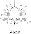
どうすれば連続操業できるかを、図2に示す。
【0055】
スラリー7は、流入パイプ10内を案内され、該パイプは、とりはずせる磁石9たとえば電磁石が取りつけてある二つのパイプ11と12に枝分かれし、そのあとこれらのパイプはふたたび一体になって流出パイプ13となる。
【0056】
パイプ11と12それぞれの磁石9の上流には、止め弁14が配置してあり、一方パイプ11と12それぞれのこれらの磁石9の下流にも止め弁15が取りつけてある。
【0057】
各止め弁14と磁石9との間には、各パイプ11および12に対して水供給ライン16が接続されており、一方各止め弁15の下流には、鉄金属8のための排出パイプ18が接続してあり、該パイプは止め弁17によって流れを止めることができる。
【0058】
通常の動作においては、止め弁14と15は、パイプ11と12のどちらか一方たとえばパイプ11において開いている。他の止め弁14と15および止め弁17は閉じてあり、また水供給ライン16からの水は供給されない。
【0059】
スラリー7に含まれる鉄金属8は、スラリー7のすぐそばに配置されている磁石9によって、使用中のパイプ11内に保持される。
【0060】
ある時間が経過したら、もう一つのパイプ12の止め弁14および15が開放され、一方、パイプ11の止め弁14および15は閉じられて、該パイプに接続されている排出パイプ18の止め弁17が開放される。磁石9がパイプ11からとりはずされ、したがって鉄金属8はもはや保持されない。水供給ライン16から水を注入することにより、これらの鉄金属8は、開放された止め弁17および排出パイプ18を通って、パイプ11から排出される。
【0061】
次に、水の供給が停止され、前記止め弁17がふたたび閉じられる。電磁石9はふたたびパイプ11の最初の位置に配置される。
【0062】
しばらくの間、鉄金属8がもう一つのパイプ12内でもう一つの電磁石9によってスラリー7から除去される。
【0063】
このパイプ12からの鉄金属8の排出は、パイプ11に関して前述したものと同様になされるが、一方ではこのパイプ11の止め弁14および15がふたたび開放され、したがって鉄金属8は第一のパイプ11内でふたたび分離できるようになる。
【0064】
このように、パイプ11と12の両方が交互に使用されて、鉄金属8が除去される。
【0065】
これらすべての実施形態において、磁気的なやり方で鉄金属8が除去されたスラリー19は脱水装置20たとえば遠心分離機に送られ、ここでスラリーは脱水される。固形物質含有率が5%よりも小さな分離水は、希釈装置2に再循環させられる。
【0066】
この脱水は、二つ以上のステップで実施することができ、このとき最後のステップは機械的な脱水であり、一つの先行ステップは凝集手段の添加ありまたはなしの沈降または浮選である。
【0067】
脱水された画分21は低濃度の重金属を含有している。重金属の一部は鉄金属8に付着しており、磁石9によって鉄金属とともに保持されるからである。この画分21はごみとして捨てることができ、あるいはたとえば堆肥化することができる。
【0068】
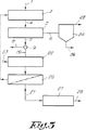
スラリー19には、鉄金属8の磁気的除去と脱水との間に、通気処理または酸化を行うことができ、たとえば通気装置22によって通気することができる。通気装置22には、図3に示すように、パイプ23により、空気が吹き込まれる。
【0069】
この実施形態は、前記実施形態とは、さらに、粗画分6が、ふるい分けから、有機または木質分および合成物質分から成る画分25が不活性成分26から分離される分離装置24たとえば沈降タンクまで、案内される、という点でも異なっている。
【0070】
脱水装置20からの脱水画分21は、生物学的に処理され、たとえば堆肥化装置27により処理されて、堆肥28となる。
【0071】
廃棄物1がまだ通気法による発酵処理を受けていない場合、堆肥化装置の代わりに発酵タンクを使用することができる。
【0072】
前記のやり方による鉄金属8の除去は、ある種の用途に対しては十分なものでありうるが、有機分を含む大部分の廃棄物の場合、得られる最終画分の重金属含有率がまだ大きすぎる。
【0073】
これを避けるために、図4に示す装置による実施形態を考えることができる。この装置は、鉄金属の磁気分離と通気装置22またはこの通気装置22が使用されていない場合脱水装置20との間に下記の他の装置が配置されている、という点で図3に示す装置とは異なる。
【0074】
磁石9のあとに、回転流によって作動する分離機29が取りつけられ、該分離機によって、非鉄金属30がスラリー19から分離される。
【0075】
次に、砂分離機32たとえばハイドロサイクロンが取りつけられ、該分離機において、砂画分33が残留スラリー31から分離される。この砂画分33から、第二の砂分離機34たとえば第二のハイドロサイクロンにおいて、残りの有機成分および他の望ましくない成分を除去して、固形有機成分の比率を減少させ、かなり純粋で、再使用できる砂画分35を得ることができる。
【0076】
この第二の砂分離機34で分離された有機スラリー36は、砂分離機32から生じるやはり有機成分に富むスラリー37と混合され、得られるスラリー38は、次に、少なくとも一つの方向における、好ましくは少なくとも二つの固定方向における寸法が2mm以下である粒子を通過させうる目を有するふるい分け装置39によって微細ふるい分けされる。このふるい分け装置39は、たとえば直径2mmの円形の目または辺が2mmの正方形の目を有する。
【0077】
ふるい分け装置39により、一方では微細スラリー40が得られ、他方では繊維画分41が得られる。後者の画分は、第三のふるい分け装置42たとえばかご形(basket)ふるいまたは回転ふるいに送られ、このふるいにおいて、重金属濃度の低い繊維43が、合成物質、金属とこれに結びついた汚染物質、およびその他の望ましくない物質を含む画分44から、たとえばふるい分けによって分離される。
【0078】
この第三のふるい分け装置42は、少なくとも一つの寸法が500μmよりも小さい粒子のみを通過させ、該装置は、たとえば500μmよりも小さな直径を有する円形の目または辺が500μmよりも短い正方形の目を有する。この場合、第一のふるい分け装置5の目の前記寸法は、好ましくは5mmよりも小さく、また第二のふるい分け装置39の寸法は1mmよりも小さい。
【0079】
鉄金属8に付着しておらず、分離機29によって分離されていない残留重金属の最大部分を含む、2mmよりも小さい粒子寸法を有する微細スラリー40は、脱水装置20によって直接脱水することができ、また重金属の初期濃度と堆肥28に対する規格要件に応じて、堆肥化装置27において堆肥化することができる。
【0080】
この堆肥化装置には、砂画分33、または好ましくは砂画分35および/または繊維画分41、または好ましくは繊維43を、図4に破線で示すように、加えることができる。場合によっては、これらの画分または繊維から、化学的なやり方たとえばキレート化剤によって少量残留している重金属を除去することもできる。
【0081】
繊維43は、通気処理に必要な構造材(structure material)を与え、一方スラリー40は、生物学的活性のために必要な窒素を供給する。
【0082】
堆肥28は、汚染物質たとえば合成物質およびガラスの濃度が割合に低い高品質の堆肥である。
【0083】
すでに述べたように、スラリー40への通気言い換えるとその酸化は、脱水たとえば0.1〜72時間の脱水の前に、実施することができる。通気装置22には、酸化剤を供給することができる。この酸化は脱水を促進する。
【0084】
この通気または酸化には、図4に示すように、沈降装置45における、重力による沈殿または沈降およびこれと同時の浮選を先行させることができ、ここでスラリー40は高密度になり、したがって通気と脱水が少なくてすむ。排出された水45Aは希釈装置2のための水3に加えられる。
【0085】
前記方法の使用により、下記の表に示す結果が得られた。
【0086】
【表1】

この表において、Aは、砂分離機32通過後の砂画分33、Bは、第二の砂分離機34通過後の砂画分35、Cは、ふるい39における微細ふるい分け後の繊維画分41、Dは、繊維43、Eは、脱水画分、Fは、キレート化剤による追加純化後のスラリー、である。
【0088】
図5に示す装置により、さらに少ない水消費で、さらに高品質の堆肥が得られる。この装置が図4に示す装置と一致する部分では、同じ装置と流れとは同じ参照番号で示す。
【0089】
廃棄物1はまず希釈装置2で希釈されてから、ふるい分け装置5でふるい分けされる。粗画分6が、分離装置24たとえば沈降タンクで、重画分すなわちガラスと石を含み、たとえば沈降物を形成する不活性画分26と、たとえば浮遊画分を形成する有機、木質、および合成物質画分25とに分離される。後者は、脱水装置46によって脱水される。分離された水47をスラリー7に加えてから、スラリー7に磁気的処理を加える。
【0090】
この場合、たとえば分離機29による分離はないが、砂分離機32からのスラリー38と微細ふるいからのスラリー40との両方を、前記の磁石9に類似の磁石48、49それぞれによって磁気的に処理することができる。
【0091】
各磁石9,48,および49の前またはあとに、非鉄金属の除去のために、回転流によって作動する分離機29を取りつけることができる。簡明なように、そのような分離機29は、図4にのみ示す。
【0092】
砂分離機32からの砂画分33は、第二の砂分離機34に供給して、有機固形物質の比率を低下させる前に、まず脱水装置50で脱水し、その水51をスラリー37に加え、そのあと固形砂画分をミキサー52のタンク54での物理/化学的水処理から生じる水53と混合する。
【0093】
第二の砂分離機34のあとでも、砂画分35を脱水装置55で脱水し、これからの水56をタンク54に集める。第二の砂分離機34からの有機スラリー36を砂分離機33からの有機スラリー37に加え、これらに同時に磁石48による処理を加え、さらに鉄金属48Aを分離してから、ふるい39により微細ふるい分けを行う。
【0094】
変形実施形態においては、脱水装置50および55を、沈降物が砂画分である沈降タンク、または他の適当な装置、で置き換えることができる。
【0095】
繊維画分41は、ふるい分け装置42でふたたびふるい分けする前に、スラリーとして湿式磁石57によって磁気的に処理され、該スラリーからさらなる量の分散鉄金属58が除去される。得られるスラリー59は、脱水装置60によって脱水され、ミキサー61において、タンク54からやってくる水53と混合される。
【0096】
ふるい分け装置42または他の分離装置によって、合成物質、これと結びついた金属、およびその他の物質から分離された繊維43は、脱水装置62によって脱水され、これから生じる水63はタンク54に集められて、たとえば物理化学的に処理される。
【0097】
タンク54によるこの水処理、ならびに第二の砂分離機34における砂の分離および繊維画分41の希釈のためのこのタンク54からの水の使用、により、新鮮水の消費は最小限に抑えられる。
【0098】
脱水装置20から希釈装置2に送られる水3が過剰な場合にも、タンク54で処理することができる。あまり大量に処理され、したがって純化水が多すぎる場合には、排出することができる。
【0099】
脱水装置60からの水64が供給される微細ふるい39を通過したスラリー40から、磁石49により、鉄金属の最終的な微細残留物49Aが除去され、そのあと該スラリーは脱水装置20で脱水される。
【0100】
脱水画分21は、堆肥化装置27に送られる前、場合によっては純化および脱水砂画分35および脱水繊維43とともに、装置65において、活性キレート化剤を含む再生水溶液72と混合することができ、また混合または摩擦により分散させることができる。
【0101】
そのあと、画分21は、好ましくは生分解性のキレート化剤67たとえばEP−A−0,267,653号明細書に記載されているものが供給される反応器66によってさらに処理して、鉄金属とともに除去されなかった重金属のさらなる部分を溶解させて、脱水装置68における脱水時に固形物質からこれらの重金属が除去されるようにすることができる。
【0102】
金属71は、再生ユニット70において、脱水装置68からの水69から分離することができる。再生水溶液72は装置65に供給され、したがって反応器66において重金属の除去のために再使用される。
【0103】
最後に述べた、図5に示す実施形態の場合、新鮮水の使用が最小限であり、処理に使用した過剰な水を処理するための費用が小さく抑えられる。
【0104】
本発明は、決して添付の図面に示した前記実施形態に限定されるものではない。逆に、有機分を含む固形廃棄物の処理のための本発明の方法は、本発明の範囲を逸脱することなく、あらゆる種類の変形によって実施することができる。
【図面の簡単な説明】
【0105】
【図1】本発明による方法を使用するための装置のブロック図である。
【図2】鉄金属が磁石によって分離される装置の部分を詳細に示す図であるが、やはり模式図である。
【図3】本発明による方法の使用のための装置の、図1のものに類似のブロック図であるが、本発明の方法の他の実施形態に関するものである。
【図4】本発明による方法の使用のための装置の、図1のものに類似のブロック図であるが、本発明の方法の他の実施形態に関するものである。
【図5】本発明による方法の使用のための装置の、図1のものに類似のブロック図であるが、本発明の方法の他の実施形態に関するものである。
【符号の説明】
【0106】
1 固形廃棄物 2 希釈装置 3 水 4 スラリー 5 ふるい分け装置 6 粗画分 7 微細スラリー 8 鉄金属 9 磁石 10 流入パイプ 11 流入パイプ 12 流入パイプ 13 流出パイプ 14 止め弁 15 止め弁 16 水供給ライン 17 止め弁 18 排出パイプ 19 スラリー 20 脱水装置 21 脱水された画分 22 通気装置 23 パイプ 24 分離装置 25 有機または木質分および合成物質分から成る画分 26 不活性画分 27 堆肥化装置 28 堆肥 29 分離機 30 非鉄金属 31 残留スラリー 32 砂分離機 33 砂画分 34 第二の砂分離機 35 再使用できる砂画分 36 有機スラリー 37 有機成分に富むスラリー 38 スラリー 39 ふるい分け装置 40 微細スラリー 41 繊維画分 42 第三のふるい分け装置 43 重金属濃度の低い繊維 44 合成物質、金属とこれに結びついた汚染物質、およびその他の望ましくない物質を含む画分 45 沈降装置 45A 水 46 脱水装置 47 水 48 磁石 48A 鉄金属 49 磁石 49A 鉄金属の最終的な微細残留物 50脱水装置 51 水 52 ミキサー 53 水5 54 タンク54 55 脱水装置 56 水 57 湿式磁石 58 分散鉄金属 59 スラリー 60 脱水装置 61 ミキサー 62 脱水装置 63 水 64 水 65 装置 66 反応器 67 生分解性のキレート化剤 68 脱水装置 69 水 70 再生ユニット 71 金属 72 活性キレート化剤を含む再生水溶液[0001]
The present invention relates to a method for treating a solid waste containing an organic component, and relates to a method for sieving the waste by a wet method.
[0002]
In the case of separate collection of household waste, the organic content can be biologically processed to high quality compost when the organic content does not contain a major amount of heavy metals.
[0003]
The remaining residual waste, also called gray waste, also contains a certain amount of organic and recyclable material. This waste is either burned or dumped in a garbage dump, but this is relatively expensive and not environmentally friendly.
[0004]
In some cases, separate collection of household waste is not performed. This mixed household waste, which also contains a large proportion of organics, is treated in the same way as the other wastes described above.
[0005]
Equipment is made to recycle parts of the other waste and mixed waste suitable for recycling. In this facility, complete pre-sorting is performed, followed by biological treatment to obtain compost.
[0006]
The main problem in this case is the quality of the final product, especially the presence of heavy metals, especially the presence of heavy metals in compost.
[0007]
To date, screening is insufficient to produce large quantities of marketable final products that contain stabilized organics with low heavy metal concentrations.
[0008]
Over the past few years, dry sorting of other waste and mixed household waste has also been performed using sieves, magnets located above the conveyor belt, air sorters, and others. The quality of the final product is such that it is not suitable for reuse or recycling. Because dry sorting techniques are inadequate, many countries introduce separate collections of recyclable waste and biowaste to provide separate streams and are acceptable by sorting and processing We are trying to obtain quality products.
[0009]
According to known methods for treating intermediate and mixed household waste, or other solid waste containing organic matter, the waste is biologically treated through the use of aerated composting. The waste is stabilized and dried while it is composted. After that, ferrous metal and fine sand fraction are recycled. The other main part of the waste dry matter must be burned, which is very expensive.
[0010]
Wet sorting presents interesting expectations, especially in other industries premixed in the usual way, mixed waste containing organics from household waste, and similar industries to household waste That is the case with waste.
[0011]
Ferrous metal removal by magnets attached to or suspended on waste conveyor equipment is limited to large pieces attracted by the magnets. Many small particles remain embedded in the waste.
[0012]
Most devices for the treatment of solid household waste do not reduce the organic content below 20 mm. This is because the cost for that increases rapidly with the degree of size reduction.
[0013]
Wet sorting gives the possibility of separating the particles by adding large amounts of water, so that each component can be accessed for sorting.
[0014]
However, so far, the use of wet sorting methods is limited. This method generally results in highly contaminated wastewater, which is more expensive to treat.
[0015]
In an aerated composting facility with an ideal solids content of about 50%, excess wastewater is generated by adding a small amount of water, so it is not possible to recycle this wastewater inside the composting device. Can not.
[0016]
Methods that use anaerobic fermentation offer greater potential for wet sorting. Because this fermentation takes place in a moist environment compared to aerobic composting, often excess wastewater cannot be avoided and therefore anyway, equipment for water removal and wastewater treatment is needed. Because it becomes.
[0017]
Anaerobic fermentation of waste can be carried out by wet fermentation with less than 15% dry matter in the reactor, but can also be carried out by dry fermentation with more than 15% dry matter in the reactor.
[0018]
A method of using wet fermentation for the treatment of wastes sorted at the source is known as contamination before carrying out wet fermentation, as described, for example, in EP-A-0,520,172. It is configured to remove substances such as suspended solids and large substances and to obtain a fraction rich in organic matter and low in pollutants.
[0019]
According to this last method, the solid component is separated before the ferrous metal is separated from the dry waste by the magnet and after water is added, after which the residue is subjected to wet fermentation. .
[0020]
An apparatus suitable for wet sorting of heavy agglomerates from mixed household waste or similar waste is described in EP-A-0,228,724. Stones, ceramic materials, batteries, and heavy chunks, for example some chunks of synthetic material, are separated by a separation tank filled with water before carrying out the biological treatment, resulting in a compost that is largely free of large components To be done.
[0021]
The treatment of mixed household solid waste can also include wet pretreatment for pulping or wet sieving, followed by separation by a hydrocyclone.
[0022]
In the known method as described above, waste containing organic components is first pretreated by a dry sorting device, and at this time, combustible fractions, ferrous metals, and other substances are recycled.
[0023]
The mixed organic waste is separated by sieving, diluted with water and then sent to a hydrocyclone where large inert components are separated.
[0024]
The remaining fine organic matter is separated by sieving and then sent again to the hydrocyclone where the sand fraction is removed. This last fraction is dehydrated.
[0025]
The sieved organic crude fraction is mixed with synthetic material and other undesirable debris that have already been separated and reduced by a crushing mill.
[0026]
Finally, the residual organic fraction is fermented.
[0027]
However, since the separation is performed before fermentation, the water is very contaminated. This is because all soluble components such as organic fatty acids, sugar, etc. are present in the waste. In addition, large amounts of water are required and separation is inadequate due to waste heterogeneity. Waste still contains sticky and malodorous organics that must be degraded in subsequent fermentation or composting.
[0028]
In fact, only sand is obtained as a recyclable material.
[0029]
In other known methods, the material is separated after fermentation or composting of the organic fraction. US-A-4,079,837 describes a method for recycling recyclable materials after crushing by explosive decompression by heat and subsequent biodegradation by composting. . Crushed and composted waste residue is separated into several fractions by normal dry sieving and air separation. Synthetic material is separated by flotation.
[0030]
Fine sand, earth, and other inert materials are separated during post-hydrolysis treatment in a two-phase fermentation, as described in EP-A-0,142,873. can do.
[0031]
All of the above-mentioned methods, including wet processing, result in poor quality compost and secondary materials, most of which are too heavy in heavy metal content. This is especially true when other household or mixed waste is used as the substrate.
[0032]
The beneficial effects of biological treatment are often limited to the recycling of energy, mainly in the form of biogas, and the generation of a high calorific fraction during dry sorting during pretreatment.
[0033]
The object of the present invention is to provide a method for the treatment of solid waste containing organic components which makes it possible to obtain a final product which does not have the abovementioned drawbacks and does not contain a large proportion of heavy metals.
[0034]
This object is achieved by the present invention. One or more of mixed household waste, industrial waste that can be compared to household waste or other waste, or waste of the type of waste originating from composting or fermenting equipment A slurry is produced by diluting the waste from the portion containing organic matter resulting from dry sorting with water, and the slurry is in the range of 2-20 mm in at least one direction to retain the crude fraction. Sieving by a first sieving device that passes debris having a certain dimension, after which a portion of the ferrous metal present in the waste is removed from the waste by means of a magnet from the passed slurry, and finally , Dehydrate the slurry And dehydrated fraction This is accomplished by recirculating the water in the dehydration process and using it to dilute the waste.
[0035]
It is known that heavy metals are usually attached to ferrous metals, so removal of the latter reduces the concentration in the remaining waste.
[0036]
According to the present invention, the dilute slurry can be produced in an independent stage that is carried out immediately before or during sieving. However, dilution into the slurry can also be performed during pretreatment, for example, when the dry matter content is low, during anaerobic fermentation or hydrolysis.
[0037]
Preferably, the diluted waste is screened to a slurry with a dry matter content of less than 10%.
[0038]
Preferably, after separation of ferrous metal and after dehydration of the slurry, the dehydrated fraction obtained is biologically treated. I.e. composting or fermentation Is added.
[0039]
The slurry can be aerated between sieving and ferrous metal removal.
[0040]
After removal of the ferrous metal, the sand can be removed from the slurry, for example by at least one hydrocyclone, and also, for example, debris having a dimension of less than 2 mm in at least one direction, preferably in at least two fixing directions. The fibrous material can be removed from the slurry by sieving with the aid of at least one sieving device through which the water is passed.
[0041]
Hereinafter, in order to better explain the features of the present invention, a preferred embodiment of a method for treating solid waste containing organic components according to the present invention will be described with reference to the accompanying drawings. This is an example and does not limit the invention in any way.
[0042]
In the case of the treatment according to the invention of the
[0043]
The
[0044]
If the waste is derived from anaerobic fermentation or hydrolysis, dilution can be performed during this pretreatment. This fermentation or hydrolysis can be carried out with less than 10% dry matter. In that case, the diluting device consists of an anaerobic fermentation tank or a hydrolysis tank.
[0045]
In the resulting slurry 4, a large amount of solid material is dispersed. This slurry is then screened by a
[0046]
If the slurry 4 contains a mass, it can be mechanically acted upon dilution or sieving, for example by mechanical mixing or agitation, so that the mass is destroyed by friction or the like.
[0047]
In order to speed up the sieving, one or more powerful jets can be applied to the slurry 4, at which time these jets push the slurry and pass through the sieving device, further breaking up the mass in the slurry. You can make it.
[0048]
Furthermore, the
[0049]
The crude fraction 6 is discharged for further processing. In a subsequent stage, the largest part of the ferrous metal 8 is separated from the
[0050]
For this purpose, the
[0051]
The magnet 9 with the iron metal 8 attached is sometimes taken out of the pipe. The iron metal 8 attached to the magnet 9 is removed before returning the magnet 9 to its original position.
[0052]
Instead of being placed directly in the
[0053]
In either embodiment, it is necessary to temporarily stop the separation in order to remove the ferrous metal 8.
[0054]
Fig. 2 shows how continuous operation is possible.
[0055]
The
[0056]
[0057]
Between each
[0058]
In normal operation,
[0059]
The ferrous metal 8 contained in the
[0060]
After a certain time, the
[0061]
Next, the supply of water is stopped and the
[0062]
For some time, ferrous metal 8 is removed from the
[0063]
The discharge of the ferrous metal 8 from this
[0064]
Thus, both the
[0065]
In all these embodiments, the
[0066]
This dehydration can be carried out in two or more steps, with the last step being mechanical dehydration and one preceding step being sedimentation or flotation with or without the addition of agglomeration means.
[0067]
The
[0068]
The
[0069]
This embodiment is further different from the previous embodiment in that the crude fraction 6 is separated from the sieving to a
[0070]
The
[0071]
If the
[0072]
The removal of ferrous metal 8 in the manner described above may be sufficient for certain applications, but for most wastes containing organics, the heavy metal content of the final fraction obtained is still Too big.
[0073]
To avoid this, an embodiment with the device shown in FIG. 4 can be considered. This apparatus is the apparatus shown in FIG. 3 in that the following other apparatus is disposed between the magnetic separation of ferrous metal and the
[0074]
After the magnet 9, a separator 29 operated by a rotating flow is attached, and the
[0075]
Next, a
[0076]
The
[0077]
By means of the
[0078]
This
[0079]
[0080]
To this composting apparatus, a
[0081]
The
[0082]
The
[0083]
As already mentioned, aeration to the
[0084]
This aeration or oxidation can be preceded by gravity precipitation or settling and flotation at the same time in the
[0085]
Use of the method gave the results shown in the table below.
[0086]
[Table 1]
In this table, A is the
[0088]
With the apparatus shown in FIG. 5, higher quality compost can be obtained with less water consumption. Where this device matches the device shown in FIG. 4, the same device and flow are indicated by the same reference numerals.
[0089]
The
[0090]
In this case, for example, there is no separation by the separator 29, but both the
[0091]
Before or after each
[0092]
The
[0093]
Even after the
[0094]
In an alternative embodiment, the
[0095]
The fiber fraction 41 is magnetically treated as a slurry by a
[0096]
The
[0097]
This water treatment by
[0098]
Even when the water 3 sent from the
[0099]
The final fine residue 49A of iron metal is removed by the
[0100]
The
[0101]
The
[0102]
The
[0103]
Finally, in the case of the embodiment shown in FIG. 5, the use of fresh water is minimal and the costs for treating excess water used for treatment are kept small.
[0104]
The present invention is in no way limited to the embodiments shown in the accompanying drawings. Conversely, the method of the present invention for the treatment of solid waste containing organic components can be carried out by any kind of modification without departing from the scope of the present invention.
[Brief description of the drawings]
[0105]
FIG. 1 is a block diagram of an apparatus for using the method according to the present invention.
FIG. 2 shows in detail the part of the device in which ferrous metal is separated by magnets, but is also a schematic view.
FIG. 3 is a block diagram similar to that of FIG. 1 of an apparatus for use of the method according to the invention, but with respect to another embodiment of the method of the invention.
FIG. 4 is a block diagram similar to that of FIG. 1 of an apparatus for use of the method according to the invention, but relating to another embodiment of the method of the invention.
FIG. 5 is a block diagram similar to that of FIG. 1 of an apparatus for use of the method according to the invention, but relating to another embodiment of the method of the invention.
[Explanation of symbols]
[0106]
DESCRIPTION OF
Claims (25)
混合家庭廃棄物、家庭廃棄物又はその他の廃棄物と比較できる産業廃棄物、又は、堆肥化装置又は発酵装置が起源である廃棄物の型の廃棄物の1つ以上の乾燥選別の結果得られる有機物を含む部分からの廃棄物(1)を水(3)で希釈することによりスラリー(4)を生成し、このスラリーを、粗画分を保持する為に、少なくとも一つの方向において、2〜20mmの範囲にある寸法を有する破片を通過させる第1のふるい分け装置(5)によって、ふるい分けし、その後、通過したスラリー(7)から、廃棄物(1)中に存在する鉄金属(8)の一部を、磁石によって前記廃棄物から除去し、 最後に、スラリー(7)を脱水して脱水画分(21)とし、脱水過程の水が再循環され、廃棄物の希釈に使用されることを特徴とする方法。In a method for treating solid waste containing organic content, wherein the waste (1) is screened by a wet method,
Resulting from one or more dry sorting of mixed household waste, industrial waste that can be compared to household waste or other waste, or waste of the type of waste originating from composting or fermenting equipment The slurry (4) is produced by diluting the waste (1) from the part containing organic matter with water (3), and this slurry is added in at least one direction in order to retain the crude fraction. Sieving by means of a first sieving device (5) that passes debris having a size in the range of 20 mm and then from the passed slurry (7) of ferrous metal (8) present in the waste (1) A part is removed from the waste with a magnet, and finally the slurry (7) is dehydrated into the dehydrated fraction (21), and the water in the dewatering process is recycled and used to dilute the waste. A method characterized by.
Applications Claiming Priority (3)
| Application Number | Priority Date | Filing Date | Title |
|---|---|---|---|
| BE2000/0180 | 2000-03-08 | ||
| BE2000/0180A BE1013344A3 (en) | 2000-03-08 | 2000-03-08 | METHOD FOR TREATING SOLID WASTE WITH AN ORGANIC FR ACTION. |
| PCT/BE2001/000037 WO2001066257A1 (en) | 2000-03-08 | 2001-03-06 | Method for treating solid waste with an organic fraction |
Publications (3)
| Publication Number | Publication Date |
|---|---|
| JP2003525742A JP2003525742A (en) | 2003-09-02 |
| JP2003525742A5 JP2003525742A5 (en) | 2005-12-22 |
| JP4237962B2 true JP4237962B2 (en) | 2009-03-11 |
Family
ID=3896447
Family Applications (1)
| Application Number | Title | Priority Date | Filing Date |
|---|---|---|---|
| JP2001564900A Expired - Lifetime JP4237962B2 (en) | 2000-03-08 | 2001-03-06 | Method for treating solid waste containing organic matter |
Country Status (17)
| Country | Link |
|---|---|
| US (1) | US6824686B2 (en) |
| EP (1) | EP1261432B1 (en) |
| JP (1) | JP4237962B2 (en) |
| KR (1) | KR100679500B1 (en) |
| CN (1) | CN1197656C (en) |
| AT (1) | ATE271423T1 (en) |
| AU (2) | AU2001239029B2 (en) |
| BE (1) | BE1013344A3 (en) |
| BR (1) | BR0109052B1 (en) |
| CA (1) | CA2401997C (en) |
| DE (1) | DE60104401T2 (en) |
| DK (1) | DK1261432T3 (en) |
| ES (1) | ES2223803T3 (en) |
| PL (1) | PL191394B1 (en) |
| PT (1) | PT1261432E (en) |
| TR (1) | TR200402229T4 (en) |
| WO (1) | WO2001066257A1 (en) |
Families Citing this family (15)
| Publication number | Priority date | Publication date | Assignee | Title |
|---|---|---|---|---|
| US20070012597A1 (en) * | 2005-07-13 | 2007-01-18 | Crystal Filtration Company | Process and apparatus for filtering metal working fluid containing metal fines |
| WO2008051876A2 (en) * | 2006-10-20 | 2008-05-02 | Don Shubin | Systems and methods for dewatering and treating waste |
| DE102007056916B4 (en) * | 2007-11-19 | 2014-08-21 | Meri Entsorgungstechnik für die Papierindustrie GmbH | Plant and process for the production of biogas |
| US8258364B2 (en) | 2008-06-16 | 2012-09-04 | Renaud Regis P | Method for steam biomass reactor |
| CA2811401C (en) | 2009-10-28 | 2017-10-03 | Magnetation, Inc. | Magnetic separator |
| KR101033023B1 (en) | 2010-09-01 | 2011-05-09 | 한라건설주식회사 | Method and system for treating contaminated dredged material for increasing reuse part |
| UA107669C2 (en) * | 2010-11-09 | 2015-02-10 | Kompoferm Gmbh | Method for treating waste |
| WO2012145658A1 (en) | 2011-04-20 | 2012-10-26 | Magnetation, Inc. | Iron ore separation device |
| US8329455B2 (en) | 2011-07-08 | 2012-12-11 | Aikan North America, Inc. | Systems and methods for digestion of solid waste |
| JP6138792B2 (en) * | 2011-09-06 | 2017-05-31 | アナエコー リミテッド | Solid waste separation and treatment methods |
| US20170209870A1 (en) * | 2014-05-22 | 2017-07-27 | Tav Holdings, Inc. | System and method for recovering metals from a waste stream |
| FR3066190B1 (en) | 2017-05-10 | 2020-12-04 | Suez Groupe | ORGANIC DRY TREATMENT PROCESS OF ORGANIC WASTE |
| CN112705550B (en) * | 2020-12-02 | 2022-11-08 | 瑞泰境美(山东)环保科技有限公司 | Solid waste treatment device with screening function |
| CN112844798A (en) * | 2021-01-11 | 2021-05-28 | 卞直旭 | Environment-friendly gold extraction device and gold extraction method |
| US20240092670A1 (en) * | 2022-09-16 | 2024-03-21 | Agro-Synergies LLC | Systems and methods for removal of methane from a methane containing digestate/fluids/substrates from methane producing systems |
Family Cites Families (9)
| Publication number | Priority date | Publication date | Assignee | Title |
|---|---|---|---|---|
| US4077847A (en) * | 1975-08-11 | 1978-03-07 | Occidental Petroleum Corporation | Solid waste disposal system |
| GB1498767A (en) * | 1976-04-15 | 1978-01-25 | Siebtech Gmbh | Refuse sorting process and plant |
| US4624417A (en) * | 1983-06-17 | 1986-11-25 | Newest, Inc. | Process for converting solid waste and sewage sludge into energy sources and separate recyclable by-products |
| US6592876B1 (en) * | 1993-04-20 | 2003-07-15 | Uab Research Foundation | Pneumococcal genes, portions thereof, expression products therefrom, and uses of such genes, portions and products |
| DE4120808A1 (en) * | 1991-06-24 | 1993-01-14 | Recycling Energie Abfall | REPROCESSING OF WASTE FOR ANAEROBIC PLANNING OF ORGANIC BIOGENIC COMPONENTS OF WASTE, ESPECIALLY OF BIOMUELL, WET WASTE, RESIDUAL WASTE AND COMMERCIAL WASTE |
| AU7122894A (en) * | 1993-06-28 | 1995-01-17 | Unilever Plc | Reduced fat renneted cheese product and a process of manufacturing it |
| GR1002461B (en) * | 1995-12-29 | 1996-11-01 | Industrial exploitation of waste materials with complete material recycling and optimisation of product's and energy generation. | |
| DE60114863T2 (en) * | 2000-08-22 | 2006-09-14 | Green Farm Energy A/S Af Juli 2004, Laurbjerg | CONCEPT FOR SEPARATION OF BATTERY AND PRODUCTION OF BIOGAS |
| CA2517440C (en) * | 2003-03-28 | 2012-09-18 | Ab-Cwt, Llc | Process and apparatus for conversion of organic, waste, or low-value materials into useful products |
-
2000
- 2000-03-08 BE BE2000/0180A patent/BE1013344A3/en not_active IP Right Cessation
-
2001
- 2001-03-06 AU AU2001239029A patent/AU2001239029B2/en not_active Expired
- 2001-03-06 WO PCT/BE2001/000037 patent/WO2001066257A1/en active IP Right Grant
- 2001-03-06 CN CNB018062229A patent/CN1197656C/en not_active Expired - Lifetime
- 2001-03-06 PT PT01913398T patent/PT1261432E/en unknown
- 2001-03-06 EP EP01913398A patent/EP1261432B1/en not_active Expired - Lifetime
- 2001-03-06 KR KR1020027011771A patent/KR100679500B1/en active IP Right Grant
- 2001-03-06 ES ES01913398T patent/ES2223803T3/en not_active Expired - Lifetime
- 2001-03-06 DK DK01913398T patent/DK1261432T3/en active
- 2001-03-06 BR BRPI0109052-6A patent/BR0109052B1/en not_active IP Right Cessation
- 2001-03-06 US US10/220,842 patent/US6824686B2/en not_active Expired - Lifetime
- 2001-03-06 PL PL364998A patent/PL191394B1/en unknown
- 2001-03-06 DE DE2001604401 patent/DE60104401T2/en not_active Expired - Lifetime
- 2001-03-06 JP JP2001564900A patent/JP4237962B2/en not_active Expired - Lifetime
- 2001-03-06 AU AU3902901A patent/AU3902901A/en active Pending
- 2001-03-06 CA CA 2401997 patent/CA2401997C/en not_active Expired - Lifetime
- 2001-03-06 TR TR200402229T patent/TR200402229T4/en unknown
- 2001-03-06 AT AT01913398T patent/ATE271423T1/en active
Also Published As
| Publication number | Publication date |
|---|---|
| KR100679500B1 (en) | 2007-02-07 |
| BR0109052A (en) | 2003-06-03 |
| CN1197656C (en) | 2005-04-20 |
| CA2401997C (en) | 2009-11-10 |
| US20030024876A1 (en) | 2003-02-06 |
| PL191394B1 (en) | 2006-05-31 |
| AU3902901A (en) | 2001-09-17 |
| WO2001066257A1 (en) | 2001-09-13 |
| BR0109052B1 (en) | 2010-02-23 |
| KR20020086620A (en) | 2002-11-18 |
| EP1261432A1 (en) | 2002-12-04 |
| CN1416371A (en) | 2003-05-07 |
| CA2401997A1 (en) | 2001-09-13 |
| ES2223803T3 (en) | 2005-03-01 |
| US6824686B2 (en) | 2004-11-30 |
| DK1261432T3 (en) | 2004-11-01 |
| JP2003525742A (en) | 2003-09-02 |
| EP1261432B1 (en) | 2004-07-21 |
| AU2001239029B2 (en) | 2004-10-14 |
| TR200402229T4 (en) | 2004-10-21 |
| DE60104401T2 (en) | 2005-09-08 |
| PT1261432E (en) | 2004-11-30 |
| PL364998A1 (en) | 2004-12-27 |
| DE60104401D1 (en) | 2004-08-26 |
| BE1013344A3 (en) | 2001-12-04 |
| ATE271423T1 (en) | 2004-08-15 |
Similar Documents
| Publication | Publication Date | Title |
|---|---|---|
| JP3041136B2 (en) | Method and apparatus for treating organic waste | |
| JP4237962B2 (en) | Method for treating solid waste containing organic matter | |
| AU2001239029A1 (en) | Method for treating solid waste with an organic fraction | |
| JPH11221541A (en) | Method for recycling organic waste | |
| US6988682B2 (en) | Method and system for utilizing waste | |
| KR100215585B1 (en) | System for making barnyard manure nourishment waste and night soil | |
| JP2005028290A (en) | Treatment method for soil polluted with heavy metal | |
| RU2226435C2 (en) | Waste mixture separation method | |
| AU738103B2 (en) | Process for splitting residues to obtain secondary raw materials | |
| KR980000658A (en) | Composting and Feeding System of Food Waste and Manure | |
| JP2004160340A (en) | Method and equipment for treating organic waste water and sludge | |
| WO1995004153A1 (en) | Method and system for the biological treatment of waste | |
| JP2000189941A (en) | Waste treatment and device therefor | |
| CZ37599A3 (en) | Process of treating waste and apparatus for making the same | |
| JP2023115530A (en) | Method for removing chrome and lead from metal-containing combustible waste | |
| CZ2017167A3 (en) | A method of decontamination of soils contaminated with petroleum substances and a line for implementing this method | |
| JP2005324129A (en) | Method for treating shells |
Legal Events
| Date | Code | Title | Description |
|---|---|---|---|
| A621 | Written request for application examination |
Free format text: JAPANESE INTERMEDIATE CODE: A621 Effective date: 20040319 |
|
| A521 | Request for written amendment filed |
Free format text: JAPANESE INTERMEDIATE CODE: A523 Effective date: 20050125 |
|
| A131 | Notification of reasons for refusal |
Free format text: JAPANESE INTERMEDIATE CODE: A131 Effective date: 20071204 |
|
| A601 | Written request for extension of time |
Free format text: JAPANESE INTERMEDIATE CODE: A601 Effective date: 20080303 |
|
| A602 | Written permission of extension of time |
Free format text: JAPANESE INTERMEDIATE CODE: A602 Effective date: 20080310 |
|
| A521 | Request for written amendment filed |
Free format text: JAPANESE INTERMEDIATE CODE: A523 Effective date: 20080404 |
|
| A131 | Notification of reasons for refusal |
Free format text: JAPANESE INTERMEDIATE CODE: A131 Effective date: 20080624 |
|
| A601 | Written request for extension of time |
Free format text: JAPANESE INTERMEDIATE CODE: A601 Effective date: 20080924 |
|
| A602 | Written permission of extension of time |
Free format text: JAPANESE INTERMEDIATE CODE: A602 Effective date: 20081001 |
|
| A521 | Request for written amendment filed |
Free format text: JAPANESE INTERMEDIATE CODE: A523 Effective date: 20081023 |
|
| TRDD | Decision of grant or rejection written | ||
| A01 | Written decision to grant a patent or to grant a registration (utility model) |
Free format text: JAPANESE INTERMEDIATE CODE: A01 Effective date: 20081125 |
|
| A01 | Written decision to grant a patent or to grant a registration (utility model) |
Free format text: JAPANESE INTERMEDIATE CODE: A01 |
|
| A61 | First payment of annual fees (during grant procedure) |
Free format text: JAPANESE INTERMEDIATE CODE: A61 Effective date: 20081219 |
|
| R150 | Certificate of patent or registration of utility model |
Ref document number: 4237962 Country of ref document: JP Free format text: JAPANESE INTERMEDIATE CODE: R150 Free format text: JAPANESE INTERMEDIATE CODE: R150 |
|
| FPAY | Renewal fee payment (event date is renewal date of database) |
Free format text: PAYMENT UNTIL: 20111226 Year of fee payment: 3 |
|
| FPAY | Renewal fee payment (event date is renewal date of database) |
Free format text: PAYMENT UNTIL: 20111226 Year of fee payment: 3 |
|
| FPAY | Renewal fee payment (event date is renewal date of database) |
Free format text: PAYMENT UNTIL: 20121226 Year of fee payment: 4 |
|
| R250 | Receipt of annual fees |
Free format text: JAPANESE INTERMEDIATE CODE: R250 |
|
| FPAY | Renewal fee payment (event date is renewal date of database) |
Free format text: PAYMENT UNTIL: 20131226 Year of fee payment: 5 |
|
| R250 | Receipt of annual fees |
Free format text: JAPANESE INTERMEDIATE CODE: R250 |
|
| R250 | Receipt of annual fees |
Free format text: JAPANESE INTERMEDIATE CODE: R250 |
|
| R250 | Receipt of annual fees |
Free format text: JAPANESE INTERMEDIATE CODE: R250 |
|
| R250 | Receipt of annual fees |
Free format text: JAPANESE INTERMEDIATE CODE: R250 |
|
| R250 | Receipt of annual fees |
Free format text: JAPANESE INTERMEDIATE CODE: R250 |
|
| R250 | Receipt of annual fees |
Free format text: JAPANESE INTERMEDIATE CODE: R250 |
|
| R250 | Receipt of annual fees |
Free format text: JAPANESE INTERMEDIATE CODE: R250 |
|
| R250 | Receipt of annual fees |
Free format text: JAPANESE INTERMEDIATE CODE: R250 |
|
| R250 | Receipt of annual fees |
Free format text: JAPANESE INTERMEDIATE CODE: R250 |
|
| EXPY | Cancellation because of completion of term |