JP4232271B2 - Agricultural machine - Google Patents
Agricultural machine Download PDFInfo
- Publication number
- JP4232271B2 JP4232271B2 JP12304799A JP12304799A JP4232271B2 JP 4232271 B2 JP4232271 B2 JP 4232271B2 JP 12304799 A JP12304799 A JP 12304799A JP 12304799 A JP12304799 A JP 12304799A JP 4232271 B2 JP4232271 B2 JP 4232271B2
- Authority
- JP
- Japan
- Prior art keywords
- working state
- planting
- lever
- operated
- arm
- Prior art date
- Legal status (The legal status is an assumption and is not a legal conclusion. Google has not performed a legal analysis and makes no representation as to the accuracy of the status listed.)
- Expired - Fee Related
Links
Images


Landscapes
- Transplanting Machines (AREA)
- Harvester Elements (AREA)
- Lifting Devices For Agricultural Implements (AREA)
Description
【0001】
【発明の属する技術分野】
本発明は、農作業装置を作業状態と非作業状態とに切替可能な農作業機に関する。
【0002】
【従来の技術】
農作業機の一種である田植機は、植付作業時には植付部を接地させた状態で植付部各部を作動させ、非植付作業時には植付部を地面から浮上させるとともに植付部各部の作動を停止させる。従来、これら作業状態と非作業状態との切替操作を、操縦席の側方に設けた植付昇降レバーで行っていた。この植付昇降レバーは、例えば、植付部を上昇させる「上げ」、植付部を一定高さに固定する「固定」、植付部を自動昇降制御を行う作業位置まで下降させる「自動」、及び植付部を接地させて植付作業を行う「植付」等の各操作位置を有している。
【0003】
【発明が解決しようとする課題】
したがって、植付部を作業状態から非作業状態に切り替えるには、植付昇降レバーを「植付」から「自動」及び「固定」を経由して「上げ」まで操作しなければならない。この切替操作を行うのは主に圃場の端部等で機体を旋回させる時であり、このような時に植付昇降レバーを操作するため片手をステアリングハンドルから離すと、ハンドル操作が不安定になりやすい。また、旋回時には上記切替操作やハンドル操作以外にも速度調節操作、線引きマーカの切替操作、安全確認等を行わねばならず、農作業機の運転に不慣れのオペレータにとって、これら旋回時の諸操作を適確に行うのは容易ではなかった。このため、実際には、圃場の端部付近まで移動してきたら早めに植付昇降レバーを操作することとなり、畦際いっぱいまで苗を植付けることができなかった。
【0004】
そこで、本発明は、旋回時の諸操作を無理なく行えるようにし、畦際いっぱいまで苗を植付けられるようにすることを課題としている。
【0005】
【課題を解決するための手段】
上記課題を解決するために、本発明は次のように構成した。すなわち、本発明にかかる農作業機は、農作業装置を作業状態と非作業状態とに切替可能な農作業機において、変速レバーの中空内部に摺動自在に嵌合する棒体を設けてその下端部にストッパプレートを固着し、前記変速レバーが中立から後進域へ操作されるのを規制する凸部が形成された後進規制カムに前記ストッパプレートをスプリングにより押し付けるとともに、前記変速レバーのグリップには後進域への操作を許容するために引き上げて操作するスイッチを設けて、該スイッ7と一体で回動するアームに前記棒体の上端部を連結した。
【0006】
一方、農作業装置を昇降するための昇降レバーで操作される操作アームにカラーを設けて、該カラーが位置決めアーム及び油圧アームのカラー接当面に接当することにより、油圧アームを回動して油圧バルブを切り替え、農作業装置を昇降させて作業状態と非作業状態とに切り替えるように構成した。
【0007】
そして、前記位置決めアームと前記ストッパプレートとをリフトワイヤで連結して、前記スイッチの引き上げ操作で農作業装置が非作業状態となるようにした。
【0008】
さらに、農作業装置を作業状態から非作業状態に切り替えるリフトレバーをステアリングハンドルの下側に上方及び後方に回動可能に設けて、該リフトレバーを上方に操作すると農作業装置が作動状態から非作動状態に切り替わり、リフトレバーを後方に操作すると減速するように構成した。
【0010】
この乗用田植機1は、走行車体2の後側に昇降リンク装置3を介して農作業装置である植付部4が昇降可能に装着されている。
【0011】
走行車体2は、各左右一対の前輪2a,2a及び後輪2b,2bを備えた四輪駆動車両で、機体の前部に配したミッションケース5の背面部から後方に延ばして設けたメインフレーム6の上にエンジン7が搭載されている。エンジン7の回転動力は、前進及び後進のいずれにも変速可能な油圧式無段変速装置8を経由してミッションケース5内のトランスミッションに伝達され、そこから前輪2a,2a、後輪2b,2b、及び植付部4の各駆動部に伝達される。植付部4への伝動は、ミッションケース10に内蔵された植付クラッチ(図示せず)により入・切できるようになっている。
【0012】
エンジン7の上側には操縦席10が設置され、その前方に前輪2a,2aを操向するステアリングハンドル11が設けられている。また、操縦席10から操作可能な範囲内に、トランスミッションを切り替えるチェンジレバー12、油圧式無段変速装置8を操作する変速レバー13、植付部4への伝動の入切と植付部4の昇降を行うための植付昇降レバー14、植付部4を作動状態から非作動状態に切り替えるための操作具であるリフトレバー15、昇降制御の感度を調節する感度調節レバー16等が設けられている。
【0013】
昇降リンク装置3は平行リンク構成であって、1本の上リンク20及び左右一対の下リンク21,21を備えている。これらリンク20,21,21は、その基部側がメインフレーム6の後端部に立設したリンクベースフレーム22に回動自在に取り付けられ、その先端側に連結枠23が枢結されている。連結枠23には植付部4をローリング自在に連結するローリング軸23aが設けられている。メインフレーム6に固着した支持部材と上リンク20に一体形成したスイングアーム24の先端部との間に昇降用油圧シリンダ25が介装されており、該シリンダを油圧で伸縮させることにより、上リンク20が上下に回動し、連結枠23に装着した植付部4がほぼ一定姿勢のまま昇降する。昇降用油圧シリンダ25は、リンクベースフレーム22に取り付けた油圧バルブ26によって制御する。
【0014】
植付部4は6条植えの構成となっていて、フレームを兼ねる伝動ケース30に、6条分の苗を載せておく苗載台31と、該苗載台上の苗を水田面に植え付ける6組の植付装置32,…等が組み付けられている。植付部4の下側には整地用のセンターフロート34及びサイドフロート35,35が設けられ、これらフロートを水田の泥面に接地させた状態で機体を進行させると各フロートが泥面を整地しつつ滑走する。センターフロート34は水田表土面の凹凸を検出するための接地体でもあり、植付作業時には、センターフロート34によって検出される水田表土面の凹凸に基づいて前記制御バルブ26を駆動することにより、苗の植付け深さを常に一定に維持するように植付部4を昇降制御する。
【0015】
また、植付部4の左右両側には、植付作業時に次行程における機体進路の左右中心を表土面に線引きする線引きマーカ36L,36Rが起立・転倒可能に設けられている。図3に示すように、左右の線引きマーカ36L,36Rと前記昇降用油圧シリンダ25のピストンロッド25aとがマーカワイヤ37L,37Rで繋がっていて、植付部上昇時にピストンロッド25aが突出作動すると、マーカワイヤ37L,37Rが引かれて線引きマーカ36L,36Rが起立し、植付部下降時にピストンロッド25aが引込み作動すると、マーカワイヤ37L,37Rが戻って線引きマーカ36L,36Rが転倒するようになっている。また、マーカ用ソレノイド38L,38Rによってマーカワイヤ37L,37Rが戻らないように規制すると、植付部4が下降しても、線引きマーカ36L,36Rが起立した状態のままに保たれる。
【0016】
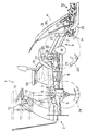
図4及び図5は植付部昇降用油圧装置と植付クラッチの切替機構を表している。次に、その構成について説明する。
【0017】
操縦席10の右側方に設けられている植付昇降レバー14は、レバー軸40回りに上下に回動操作するようになっており、操作範囲内に上から順に「上げ」「固定」「自動」「植付」の各操作位置が設定されている。レバー軸40には油圧装置と植付クラッチの切替操作用の操作アーム41が取り付けられ、この操作アーム41の先端部に軸支されているカラー42に、共通の軸44にそれぞれ回動自在に取り付けられた位置決めアーム45と油圧アーム46とが接当している。位置決めアーム45のカラー接当面には4つの凹部が形成されており、植付昇降レバー14を前記操作位置に操作すると、カラー42がそれぞれの操作位置に対応する凹部に嵌り込み、その位置で安定するようになっている。符号48は、位置決めアーム45をカラー42の側に付勢するスプリングである。
【0018】
一方、油圧アーム46のカラー接当面には段差が設けられており、植付昇降レバー14の操作位置に応じて油圧アーム46が回動し、その作用部46aが油圧バルブ26のスプール26aを押し込んだり、或は作用部46aがスプールから離れる方向に移動して油圧バルブに内蔵されたスプリングの作用でスプール26aが突出したりして油圧バルブ26を切り替える。具体的には、「固定」に操作されているときは油圧バルブ26が中立の状態にあり、「上げ」に操作れさているときは昇降用油圧シリンダ25のピストンが突出作動(植付部4が上昇)する側に油圧バルブ26が切り替わり、「自動」もしくは「植付」に操作されているときは昇降用油圧シリンダ25のピストンが引っ込み作動(植付部4が下降)する側に油圧バルブ26が切り替わる。
【0019】
また、ミッションケース10の上面に突出する植付クラッチ操作用クラッチピン50の上端部に植付クラッチアーム51の一端部が係合し、その他端部が操作アーム41の中間部と植付クラッチワイヤ52を介して結ばれている。これにより、植付昇降レバー14が「自動」もしくは「植付」に操作されているときは、クラッチピン50が押し込まれて植付クラッチが入になり、「上げ」もしくは「固定」に操作されているときは、スプリング53によってクラッチピン50が戻されて植付クラッチが切になる。
【0020】
位置決めアーム45には、後述するリフトレバー15の操作に連動させるリフトワイヤ55が連結されている。リフトレバー15を所定操作すると、リフトワイヤ55が引っ張られ、位置決めアーム45がカラー42から離れる側に回動する。すると、位置決めアーム45によるカラー42の位置規制がなくなるため、植付昇降レバー14がスプリング56によって「上げ」位置まで移動し、昇降用油圧シリンダ25のピストンが突出作動して植付部4が上昇するとともに、植付クラッチが切りになる。つまり、植付部4が作業状態にある時、リフトレバー15の操作で植付部4を非作業状態に切り替えられるのである。逆に、植付部4が非作業状態にある時にリフトレバー15を操作しても、植付部4は作業状態に切り替わらない。
【0021】
また、油圧バルブ26のスプール26aには、油圧アーム46とは別に、軸61に回動自在に取り付けられた自動昇降アーム62が接当している。この自動昇降アーム62の先端部にセンターフロート34の前部と上下動に連動する自動昇降ワイヤ63が繋着されており、植付昇降レバー14が「自動」に操作されている時にセンターフロート34の前部が上下動すると、それに応じて油圧バルブ26が適宜切り替わり植付部4を昇降させるようになっている。符号64は自動昇降アーム62を復帰させるリターンスプリングである。
【0022】
自動昇降アーム62を支持している軸61は、軸65を支点として回動自在な感度調節アーム66の先端部に設けられている。感度調節レバー16と感度調節アーム66とが感度調節ワイヤ67で結ばれている。感度調節レバー16の操作によって自動昇降アーム62の支点位置を移動させると、センターフロート34の前部の上下動に対する油圧バルブ26の切り替えの応答性が変更される。符号68は感度調節アーム66を復帰させるリターンスプリングである。
【0023】
油圧バルブ26には、昇降用油圧シリンダ25のピストンが引っ込み作動(植付部4が下降)する側に油圧バルブ26が切り替わるのを規制する下降ロックピン69が設けられている。この下降ロックピン69は、図示しない下降ロックレバーと下降ロックワイヤ70で結ばれた下降ロックアーム71によって操作される。
【0024】
前記リフトレバー15は、図6に示すように、ステアリングハンドル11の右下側の位置に、上方に回動可能に設けられている。その操作は、ステアリングハンドル11を握ったまま、指先だけを動かして行うことができる。リフトレバー15を上方に操作すると、植付部4が駆動停止及び植付部4が最上げ位置まで上昇するようになっている。すなわち、植付部4が作業状態から非作業状態に切り替わるのである。なお、ステアリングハンドル11は前後に回動可能なチルトハンドルであるが、リフトレバー15もステアリングハンドル11と一体に回動し、両者11,15の位置関係は常に変わらないようになっている。
【0025】
この乗用田植機1は以上の構成で、フロート34,35,35が接地する高さに植付部4を保持し、植付部4を駆動させつつ前輪2a,2a及び後輪2b,2bを回転させて機体を進行させると、フロート34,35,35によって整地された泥面に苗を植付ける。畦際まで苗植付けを行ったなら、植付部4の駆動停止、植付部4の最上げ位置への上昇、線引きマーカ36L,36Rの起立・転倒の切替減速等の諸操作を行うとともに、ステアリングハンドル11を操作して機体を旋回させる。
【0026】
上記植付部4の駆動停止及び植付部4の最上げ位置への上昇操作、すなわち植付部4の作業状態から非作業状態への切替操作は植付昇降レバー14及びリフトレバー15のいずれでも行うことができるが、特に旋回時等のように各種操作を行わなければならない時にはリフトレバー15で操作する方が簡単である。リフトレバー15はワンタッチ操作であるので、他の操作を余裕をもって無理なく行うことができ、その分だけ畦際いっぱいまで植付作業を行なえる。また、リフトレバー15はステアリングハンドル11を握ったまま操作できるので、ハンドル操作が乱れず安全に旋回できる。このリフトレバー15は植付部4の作業状態から非作業状態への切替だけを行い、その逆の切替は行えないので、旋回中等に誤ってリフトレバー15に触れても、植付部4が非作動状態から作動状態に切り替わるおそれがない。旋回終了後は、植付昇降レバー14の操作で植付部4を作業状態にする。
【0027】
次に、図7は異なる実施の形態におけるリフトレバーを表している。このリフトレバー15′は、上方及び後方に回動可能に設けられており、上方に操作すると植付部4が作業状態から非作業状態に切り替わり、後方に操作するとエンジンスロットルが絞られて所定速度まで減速されるようになっている。このように構成すると、旋回時における減速操作もステアリングハンドル11から手を離さず行え、操作性を更に向上させられる。なお、図6に示すリフトレバー構成で、リフトレバー15を上方に操作すると、植付部4が作業状態から非作業状態に切り替わると同時に、所定速度まで減速される構成としてもよい。
【0028】
図8はさらに異なる実施の形態におけるリフトレバーを表している。このリフトレバー15″は、上方及び前後に回動可能に設けられており、上方に操作すると植付部4が作業状態から非作業状態に切り替わり、前後に操作すると線引きマーカの線引き作用する側が左右切り替わるようになっている。すなわち、リフトレバー15″を前方に操作すると、前記マーカ用ソレノイド38RがONになり、植付部4が作業位置まで下降したときに左側の線引きマーカ36Lだけが転倒して線引き作用する状態となる。また、リフトレバー15″を後方に操作すると、前記マーカ用ソレノイド38LがONになり、植付部4が作業位置まで下降したときに左側の線引きマーカ36Rだけが転倒して線引き作用する状態となる。
【0029】
図9は変速レバーを示す図である。変速レバー13は、ステアリングハンドル11の左前方に、回動軸80を支点にして前後に回動可能に設けられている。変速レバー13の回動操作位置は検出器81に検出される。そして、変速レバー13を中立を起点にして前方に操作すると、その操作量に応じた前進速度となり、後方に操作すると、その操作量に応じた後進速度となる。
【0030】
変速レバー13の中空内部に摺動自在に嵌合する棒体83の下端部にストッパプレート84が固着され、このストッパプレート84をスプリング85によって後進規制カム86に押し付けている。後進規制カム86には、変速レバー13が中立から後進域へ操作されるのを規制する凸部86aが形成されている。また、変速レバーのグリップ13aには後進許容スイッチ87が設けられ、これと一体に回動するアーム88に棒体83の上端部が連結されている。この構成により、常態では変速レバー13を中立から後進域へ操作することはできないが、後進許容スイッチ87を引き上げ操作しながらであれば変速レバー13を中立から後進域へ操作できるようになっている。
【0031】
後進許容スイッチ87はグリップ13aの下側開口部に出入りするように設けられているとともに、アーム88は断面U字状をした後進許容スイッチ87の内側に設けられている。このようにアーム88を二重に覆う構造とすることにより、アーム88の周囲に泥水等が侵入することが防止され、上記後進許容機構の操作性を良好に維持することができる。
【0032】
また、この実施の形態では、位置決めアーム45とストッパプレート84とがリフトワイヤ90で結ばれている。これにより、後進許容スイッチ87を引き上げ操作すると、植付昇降レバー14がスプリング56によって「上げ」位置まで移動し、昇降用油圧シリンダ25のピストンが突出作動して植付部4が上昇するとともに、植付クラッチが切りになる。つまり、植付部4が作業状態にある時、後進許容スイッチ87の操作で植付部4を非作業状態に切り替えられるのである。植付部4が非作業状態にある時に後進許容スイッチ87を操作しても、植付部4は作業状態に切り替わらない。本来、後進許容スイッチ87は変速レバー13を後進域に操作するときに使用されるものであるが、本構成とすれば、植付部4を作業状態から非作業状態に切り替えるだけに後進許容スイッチ87を使用することもできる。
【0033】
【発明の効果】
以上に説明した如く、本発明にかかる農作業機は、農作業装置を作業状態から非作業状態に一つの操作で切り替えられる操作具が設けられているので、旋回時には上記操作具を使用して農作業装置を作業状態から非作業状態に切り替えることにより、旋回時の諸操作を無理なく適確に行うことができるようになった。この操作具は、誤って触れても、農作業装置が非作業状態から作業状態に切り替わることはないので安全である。さらに、農作業装置を作業状態から非作業状態に切り替えるリフトレバーをステアリングハンドルの下側に上方及び後方に回動可能に設けて、該リフトレバーを上方に操作すると農作業装置が作動状態から非作動状態に切り替わり、リフトレバーを後方に操作すると減速するように構成したので、旋回時における減速操作もステアリングハンドルから手を離さずに行えるようになり、操作性が向上した。
【図面の簡単な説明】
【図1】乗用田植機の側面図である。
【図2】乗用田植機の平面図である。
【図3】線引きマーカの作動機構を表す斜視図である。
【図4】油圧装置と植付クラッチの切替機構を表す図その1である。
【図5】油圧装置と植付クラッチの切替機構を表す図その2である。
【図6】リフトレバーの操作位置を表す(a)平面図、及び(b)側面図である。
【図7】異なる実施の形態におけるリフトレバーの操作位置を表す(a)平面図、及び(b)側面図である。
【図8】さらに異なる実施の形態におけるリフトレバーの操作位置を表す(a)平面図、及び(b)側面図である。
【図9】変速レバーの(a)一部断面側面図、及び(b)断面背面図である。
【符号の説明】
1 乗用田植機(農作業機)
2 走行車体
3 昇降リンク装置
4 植付部(農作業装置)
8 変速装置
11 ステアリングハンドル
13 変速レバー
14 植付昇降レバー
15 リフトレバー(操作具)
26 油圧バルブ
87 後進許容スイッチ[0001]
BACKGROUND OF THE INVENTION
The present invention relates to a farm work machine capable of switching a farm work device between a working state and a non-working state.
[0002]
[Prior art]
A rice transplanter, a type of farm work machine, operates each part of the planting part with the planting part grounded during planting work, and floats the planting part from the ground during non-planting work. Stop operation. Conventionally, the switching operation between the working state and the non-working state has been performed with a planting lift lever provided on the side of the cockpit. This planting lift lever is, for example, “raising” to raise the planting part, “fixing” to fix the planting part to a certain height, and “automatic” to lower the planting part to a working position where automatic lifting control is performed. And operation positions such as “planting” for performing the planting work by grounding the planting part.
[0003]
[Problems to be solved by the invention]
Therefore, in order to switch the planting part from the working state to the non-working state, the planting lift lever must be operated from “planting” to “raising” via “automatic” and “fixing”. This switching operation is mainly performed when the aircraft is swiveling at the end of the field, etc. When operating the planting lift lever in such a case, if one hand is moved away from the steering handle, the steering operation becomes unstable. Cheap. In addition to the switching operation and steering wheel operation described above, speed adjustment operations, drawing marker switching operations, safety checks, etc. must be performed during turning, and these operations during turning are appropriate for operators unfamiliar with the operation of farm equipment. It was not easy to do exactly. For this reason, in practice, the planting lift lever was operated as soon as it moved to the vicinity of the end of the field, and the seedlings could not be planted to the full edge.
[0004]
Then, this invention makes it a subject to enable it to perform various operations at the time of turning without difficulty, and to plant a seedling to the full edge.
[0005]
[Means for Solving the Problems]
In order to solve the above problems, the present invention is configured as follows. In other words, agricultural machine according to the present invention is a switchable agricultural machine farm equipment and working state and a non-working state, at its lower end provided with a rod slidably fitted in the hollow interior of the shift lever A stopper plate is fixed, and the stopper plate is pressed by a spring against a reverse control cam formed with a convex portion that restricts the operation of the shift lever from the neutral position to the reverse range. A switch that is lifted up and operated to allow the operation of the rod is provided, and the upper end of the rod is connected to an arm that rotates integrally with the
[0006]
On the other hand, a collar is provided on an operation arm operated by a lifting lever for lifting and lowering the farm work apparatus, and the collar is brought into contact with the collar abutting surface of the positioning arm and the hydraulic arm, whereby the hydraulic arm is rotated to be hydraulic. The valve was switched, and the farm work apparatus was moved up and down to switch between a working state and a non-working state.
[0007]
Then, the positioning arm and the stopper plate are connected by a lift wire so that the farm work apparatus is brought into a non-working state by a lifting operation of the switch.
[0008]
Furthermore, a lift lever for switching the farm working device from the working state to the non-working state is provided on the lower side of the steering handle so as to be pivotable upward and rearward. When the lift lever is operated backward, it is configured to decelerate.
[0010]
The
[0011]
The traveling vehicle body 2 is a four-wheel drive vehicle including a pair of left and right
[0012]
A
[0013]
The lifting / lowering
[0014]
The
[0015]
In addition, on both the left and right sides of the
[0016]
4 and 5 show a planting part raising / lowering hydraulic device and a planting clutch switching mechanism. Next, the configuration will be described.
[0017]
The
[0018]
On the other hand, a step is provided on the collar contact surface of the
[0019]
One end of the planting
[0020]
The
[0021]
In addition to the
[0022]
The
[0023]
The
[0024]
As shown in FIG. 6, the
[0025]
This riding
[0026]
The operation of stopping the
[0027]
Next, FIG. 7 shows a lift lever in a different embodiment. The lift lever 15 'is provided so as to be pivotable upward and backward, and when operated upward, the
[0028]
FIG. 8 shows a lift lever in a further different embodiment. This
[0029]
FIG. 9 is a diagram showing the shift lever. The
[0030]
A
[0031]
The
[0032]
In this embodiment, the
[0033]
【The invention's effect】
As described above, the farm work machine according to the present invention is provided with the operation tool for switching the farm work apparatus from the working state to the non-working state by one operation. By switching from the working state to the non-working state, various operations at the time of turning can be performed without difficulty. Even if the operation tool is touched by mistake, the farm work apparatus does not switch from the non-working state to the working state, and is safe. Furthermore, a lift lever for switching the farm working device from the working state to the non-working state is provided on the lower side of the steering handle so as to be pivotable upward and backward, and when the lift lever is operated upward, the farm working device is moved from the activated state to the non-operated state. Since it is configured to decelerate when the lift lever is operated backwards, the decelerating operation during turning can be performed without removing the hand from the steering wheel, improving operability.
[Brief description of the drawings]
FIG. 1 is a side view of a riding rice transplanter.
FIG. 2 is a plan view of a riding rice transplanter.
FIG. 3 is a perspective view showing an operation mechanism of a drawing marker.
FIG. 4 is a first diagram illustrating a switching mechanism between a hydraulic device and a planting clutch.
FIG. 5 is a second diagram illustrating a switching mechanism between a hydraulic device and a planting clutch.
6A is a plan view and FIG. 6B is a side view showing an operation position of a lift lever.
7A is a plan view and FIG. 7B is a side view showing an operation position of a lift lever in different embodiments. FIG.
FIG. 8A is a plan view and FIG. 8B is a side view showing an operation position of a lift lever according to another embodiment.
9A is a partial cross-sectional side view of the speed change lever, and FIG. 9B is a cross-sectional rear view.
[Explanation of symbols]
1 Passenger rice transplanter (agricultural work machine)
2 Traveling
8
26
Claims (2)
Priority Applications (1)
| Application Number | Priority Date | Filing Date | Title |
|---|---|---|---|
| JP12304799A JP4232271B2 (en) | 1999-04-28 | 1999-04-28 | Agricultural machine |
Applications Claiming Priority (1)
| Application Number | Priority Date | Filing Date | Title |
|---|---|---|---|
| JP12304799A JP4232271B2 (en) | 1999-04-28 | 1999-04-28 | Agricultural machine |
Publications (3)
| Publication Number | Publication Date |
|---|---|
| JP2000312515A JP2000312515A (en) | 2000-11-14 |
| JP2000312515A5 JP2000312515A5 (en) | 2006-06-15 |
| JP4232271B2 true JP4232271B2 (en) | 2009-03-04 |
Family
ID=14850903
Family Applications (1)
| Application Number | Title | Priority Date | Filing Date |
|---|---|---|---|
| JP12304799A Expired - Fee Related JP4232271B2 (en) | 1999-04-28 | 1999-04-28 | Agricultural machine |
Country Status (1)
| Country | Link |
|---|---|
| JP (1) | JP4232271B2 (en) |
-
1999
- 1999-04-28 JP JP12304799A patent/JP4232271B2/en not_active Expired - Fee Related
Also Published As
| Publication number | Publication date |
|---|---|
| JP2000312515A (en) | 2000-11-14 |
Similar Documents
| Publication | Publication Date | Title |
|---|---|---|
| JP4232271B2 (en) | Agricultural machine | |
| JPH0444018Y2 (en) | ||
| JP3632779B2 (en) | Mobile farm machine | |
| JP4296657B2 (en) | Rice transplanter | |
| JP2000312515A5 (en) | ||
| JP2002084831A (en) | Agricultural implement | |
| JPH0466521B2 (en) | ||
| JP3759009B2 (en) | Working vehicle lifting mechanism | |
| JP3378318B2 (en) | Agricultural work machine backup device | |
| JP2601691B2 (en) | Moving agricultural machine | |
| KR100376367B1 (en) | Seedling transplanter | |
| JPS634Y2 (en) | ||
| JPH029605Y2 (en) | ||
| JP3930141B2 (en) | Lifting control device for mobile agricultural machine | |
| JP3178006B2 (en) | Side clutch of walking rice transplanter | |
| JP2001112313A5 (en) | ||
| JPS6338731Y2 (en) | ||
| JP2588874B2 (en) | Riding seedling planter | |
| JPH0244656Y2 (en) | ||
| JPS6024093Y2 (en) | Riding rice transplanter | |
| JPS6131623Y2 (en) | ||
| JPH025690Y2 (en) | ||
| JPS6013296Y2 (en) | rice transplanter | |
| JPH032091Y2 (en) | ||
| JPH032092Y2 (en) |
Legal Events
| Date | Code | Title | Description |
|---|---|---|---|
| A521 | Written amendment |
Free format text: JAPANESE INTERMEDIATE CODE: A523 Effective date: 20060424 |
|
| A621 | Written request for application examination |
Free format text: JAPANESE INTERMEDIATE CODE: A621 Effective date: 20060424 |
|
| A977 | Report on retrieval |
Free format text: JAPANESE INTERMEDIATE CODE: A971007 Effective date: 20071227 |
|
| A131 | Notification of reasons for refusal |
Free format text: JAPANESE INTERMEDIATE CODE: A131 Effective date: 20080122 |
|
| A521 | Written amendment |
Free format text: JAPANESE INTERMEDIATE CODE: A523 Effective date: 20080324 |
|
| A521 | Written amendment |
Free format text: JAPANESE INTERMEDIATE CODE: A523 Effective date: 20080509 |
|
| TRDD | Decision of grant or rejection written | ||
| A01 | Written decision to grant a patent or to grant a registration (utility model) |
Free format text: JAPANESE INTERMEDIATE CODE: A01 Effective date: 20081118 |
|
| A01 | Written decision to grant a patent or to grant a registration (utility model) |
Free format text: JAPANESE INTERMEDIATE CODE: A01 |
|
| A61 | First payment of annual fees (during grant procedure) |
Free format text: JAPANESE INTERMEDIATE CODE: A61 Effective date: 20081201 |
|
| FPAY | Renewal fee payment (event date is renewal date of database) |
Free format text: PAYMENT UNTIL: 20111219 Year of fee payment: 3 |
|
| R150 | Certificate of patent or registration of utility model |
Free format text: JAPANESE INTERMEDIATE CODE: R150 |
|
| FPAY | Renewal fee payment (event date is renewal date of database) |
Free format text: PAYMENT UNTIL: 20141219 Year of fee payment: 6 |
|
| LAPS | Cancellation because of no payment of annual fees |