JP4222652B2 - Combination of spout and cap, and spout - Google Patents
Combination of spout and cap, and spout Download PDFInfo
- Publication number
- JP4222652B2 JP4222652B2 JP35810797A JP35810797A JP4222652B2 JP 4222652 B2 JP4222652 B2 JP 4222652B2 JP 35810797 A JP35810797 A JP 35810797A JP 35810797 A JP35810797 A JP 35810797A JP 4222652 B2 JP4222652 B2 JP 4222652B2
- Authority
- JP
- Japan
- Prior art keywords
- spout
- ring
- cap
- ratchet
- cap body
- Prior art date
- Legal status (The legal status is an assumption and is not a legal conclusion. Google has not performed a legal analysis and makes no representation as to the accuracy of the status listed.)
- Expired - Fee Related
Links
Images

Landscapes
- Closures For Containers (AREA)
Description
【0001】
【発明の属する技術分野】
本発明は注出口とキャップとの組合体、および注出口に係り、とりわけ注出口からキャップを取外したことを容易に確認することができる注出口とキャップとの組合体、および注出口に関する。
【0002】
【従来の技術】
従来より、例えば飲料水を内部に収納した柔軟容器に、注出口が取付けられており、この注出口にはキャップがねじ込まれて装着される。この場合、キャップはキャップ本体と、キャップ本件に薄肉部を介して連結されたリングとを有している。
【0003】
キャップを注出口から取外す場合、キャップのリングが注出口に固定され、キャップ本体とリングとが分離されキャップ本体のみが注出口から取外される。
【0004】
このようにキャップ取外時に、キャップ本体とリングとが分離されて、外方よりキャップ取外しを確認することができる。
【0005】
【発明が解決しようとする課題】
上述のようにキャップを注出口から取外す場合、キャップ本体とリングとが分離してキャップ本体のみが注出口から取外され、リングは注出口側へ残る。
【0006】
使用者が飲料水を注出口から飲む場合は、容器を引繰り返し注出口を使用者の口にあてて飲むことになる。この際、注出口に残ったリングが落下して、使用者の口に当たり飲みにくくなることがある。
【0007】
本発明はこのような点を考慮してなされたものであり、使用時において容器を引繰り返しても注出口に残ったリングが使用者の口に当接することのない注出口とキャップとの組合体、および注出口を提供することを目的とする。
【0008】
【課題を解決するための手段】
本発明は、フランジから外方へ突出するとともに、おねじを有する円筒状注出口と、注出口のおねじに係合するめねじを有し、注出口に装着された円筒状キャップとを備え、キャップはキャップ本体と、キャップ本体に薄肉部を介して破断可能に連結されるとともに注出口に沿って摺動可能なリングとを有し、リング内面の下端に円周突部が設けられるとともに、その上端に所定間隙をおいて複数のリングラチェットが設けられ、注出口外面には注出口からキャップを取外す際、円周方向においてリングラチェットに係合する複数の注出口ラチェットと、軸方向において円周突部に係合する止め部が所定間隔をおいて複数設けられ、注出口からキャップを取外す際に注出口ラチェットとリングラチェットが係合する場合、リングに設けられたリングラチェットは、注出口に設けられた止め部および注出口ラチェットと円周方向に関してずれて配置され、キャップを注出口に対して回転させて注出口ラチェットとリングラチェットとが係合することによりリングがキャップ本体から破断した際、リングがフランジ側に落下することを特徴とする注出口とキャップとの組合体、および
円周方向においてキャップのリングラチェットに係合する複数の注出口ラチェットと、軸方向においてキャップの円周突部に係合する止め部とが外面に設けられたことを特徴とする、上記記載の注出口とキャップとの組合体を構成する注出口である。
【0009】
本発明によれば、キャップを取外す際、注出口に対してキャップのキャップ本体を緩める方向に回転させる。この場合、注出口側の注出口ラチェットとリング側のリングラチェットとが係合し、リングが注出口に係止される。更にキャップ本体を回転させると、リングとキャップ本体との間に設けられた薄肉部が破断し、リングとキャップ本体とが分離する。キャップ本体から分離したリングはその自重で注出口を摺動しながら落下する。注出口を引繰り返すと、リングの円周突部が注出口側の止め部に係合し、リングが注出口先端側へ落下することが防止される。
【0010】
【発明の実施の形態】
以下、図面を参照して本発明の実施の形態について説明する。
図1乃至図5は本発明の実施の形態を示す図である。
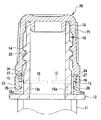
図1乃至図5に示すように、注出口とキャップとの組合体は、円筒状注出口10と、この注出口10に装着されるキャップ20とを備えている。
【0011】
このうち注出口10はフランジ12を境として図示しない容器内側へ延びる内側筒部11と、容器外側へ延びる外側筒部13とを有している。また外側筒部13の外面にはおねじ14が設けられている。
【0012】
一方、キャップ20は、外側筒部13のおねじ14に係合するめねじ22が内面に設けられたキャップ本体21と、キャップ本体21に薄肉部24を介して連結されたリング23とを有している。
【0013】
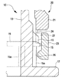
また図1および図2に示すように、リング23の下端には、内方へ突出する円周突部26が円周状に設けられており、またリング23の上端には、所定間隙をおいて複数、例えば4個のリングラチェット27が設けられている。
【0014】
なお、図1および図2に示すように、キャップ本体21とリング23との間に設けられた薄肉部24は、薄肉の柱状となっている。本実施の形態においては図1および図2に示すように、柱状薄肉部24はキャップ本体21とリング23のリングラチェット27の間に延びるとともに、円周方向に所定間隔をおいて複数(例えば4個)設けられている。また各柱状薄肉部24は、キャップ本体21からリングラチェット27側に向って先細状に形成され、水平断面が略半円形の三日月形をしている。このため柱状薄肉部24においてキャップ本体21とリング23とは容易に破断可能となっており、このとき薄肉部21の破断箇所はリング23のリングラチェット27側に位置するようになっている。
【0015】
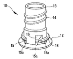
次に注出口10について、図1乃至図4により更に詳述する。図1乃至図4に示すように、注出口10の外側筒部13の外面には、リング23のリングラチェット27と円周方向において係合する注出口ラチェット16が円周方向に所定間隔において複数(例えば4個)設けられている(図4参照)。すなわち注出口10の注出口ラチェット16とリング23のリングラチェット27は、注出口10に装着されたキャップ20を取外す際互いに係合し、キャップ20のうちリング23を注出口10に残したままキャップ本体21のみを薄肉部24を介してリング23から分離して取外すためのものである。
【0016】
また、図4に示すように注出口10の外側筒部13の外面には、注出口ラチェット16より下方側にリング23の円周突部26と軸方向において係合する止め部15が円周方向に所定間隔をおいて複数(例えば4個)設けられている。この止め部15は、使用時にキャップ本体21とリング23とを薄肉部24を介して破断し、容器および注出口10を引繰り返して注出口10から容器内の内容物を飲む場合、リング23の円周突部26に係合してリング23の落下を防止するものである。また図4に示すように注出口ラチェット16と止め部15は、共に円周方向に関して所定間隔において配置されている。
【0017】
また、注出口10の外側筒部13外面に設けられた止め部15の下部には、フランジ12側へ延びる突起15aが各止め部15に複数(例えば2個)設けられている。この突起15aはキャップ本体21から分離したリング23をガタつくことなく、注出口10の外側筒部13外面に保持するものである。
【0018】
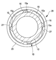
なお、図3に示すように、注出口10に装着されたキャップ20を取外す際に注出口ラチェット16とリングラチェット27が係合した場合、リング23側のリングラチェット27と、注出口10側の止め部15とは円周方向に関して互いにずれて配置されている。このためキャップ本体21とリング23とを分離した場合、リング23がスムーズに注出口10のフランジ12側へ落下するようになっている。
【0019】
また、図5に示すように、キャップ20のキャップ本体21とリング23に、キャップ20を注出口10にねじ込む際互いに係合する係合突起21a、23aが円周方向に関して相対向する位置に各々設けられている。
【0020】
このような係合突起21a、23aによって、キャップ20を注出口10にねじ込む際、薄肉部24が破断することを未然に防止することができる。
【0021】
次にこのような構成からなる本実施の形態の作用について説明する。
【0022】
まず、図示しない容器内面に対して注出口10の内側筒部11外面がヒートシールされ、このようにして注出口10が容器に取付けられる。
【0023】
次に注出口10から容器内に飲料水等の内容物が充てんされ、その後注出口10側のおねじ14とキャップ20側のめねじ22とを係合させて注出口10にキャップ20がねじ込まれ、キャップ20が注出口10のフランジ12側へ接近する。その後注出口10側の注出口ラチェット16上をキャップ20側のリングラチェット27が乗り越えて、キャップ20が注出口10に対して確実に装着される。注出口10へキャップ20をねじ込む場合、上述のように、キャップ本体21の係合突起21aとリング23の係合突起23aが係合するので、キャップ本体21とリング23との間に設けられた薄肉部24が破断することはない。
【0024】
使用に際しては、まず使用者がキャップ20のキャップ本体21を把持し、キャップ20を注出口10から緩める方向(ねじ込み方向と逆方向)に回転させる。この場合、注出口10側の注出口ラチェット16とキャップ20側のリングラチェット27とが円周方向において係合し、リング23が注出口10側に係止される。このため、キャップ本体21のみが注出口10から緩める方向に回転し、キャップ本体21とリング23との間の薄肉部24が破断してキャップ本体21とリング23とが分離する。
【0025】
上述のように薄肉部24はリング23のリングラチェット27側へ向って先細状となる柱形状を有しているので、薄肉部24はリング23のリングラチェット27側において破断する。このためリング23のキャップ本体21側の面に薄肉部24の破断端が残ることはない。
【0026】
更にキャップ本体21を注出口10に対して緩める方向に回転させることによって、注出口10側のおねじ14と、キャップ本体21側のめねじ22との係合が解除してキャップ本体21のみが注出口10から取外される。
【0027】
この間、キャップ本体21から分離したリング23は、その自重により注出口10の外側筒部13に沿って摺動しながらフランジ12側へ落下する。この場合、リング23のリングラチェット27は、注出口10側の止め部15および注出口ラチェット16のいずれとも円周方向に関して所定間隔をおいて配置されているため、リング23はその自重によってスムーズにフランジ12側へ落下することができる。また注出口10側には止め部15から延びる突起15aが設けられているので、リング23がフランジ12側へ落下する際リング23内面がこの突起15aにガイドされることになる。このためリング23の落下時にリング23が注出口10外周においてガタついて外れることはない。
【0028】
次に使用者は注出口10を容器ごと引繰り返し、注出口10を口にあてて内容物を注出口10から飲みほす。この場合、リング23の円周突部26が注出口10の止め部15に係合するので、容器を引繰り返した場合にリング23が注出口10の先端から使用者の口側へ落下してしまうことはない。また薄肉部24はリング23のリングラチェット27側において破断するので、リング23側に薄肉部24の破断端が残ることはない。このため使用者が注出口10を口にあてた場合でも、リング23に残った薄肉部24の破断端が口部に当接するということはない。
【0029】
その後使用者は、容器を注出口10が上方を向く元の状態まで戻し、次に注出口10に対してキャップ本体21を再度装着する。この場合、キャップ20はキャップ本体21とリング23とが分離した状態となっているので、外部からキャップ20を一度取外したことを容易に認識することができる。
【0030】
【発明の効果】
以上のように本発明によれば、キャップのキャップ本体を緩める方向に回転させると、注出側の注出口ラチェットとリング側のリングラチェットが係合し、その後薄肉部が破断してリングとキャップ本体とが分離する。分離したリングは注出口を摺動しながら落下する。この後キャップ本体を再度注出口に装着した場合、キャップ本体とリングとが分離しているので、外部からキャップを一度取外した事実を確認することができる。また使用時に注出口を引繰り返した場合、リングの円周突部は注出口側の止め部に係合するので、リングが注出口先端側へ落下することはない。このため、使用時に注出口を引繰り返しても、リングが邪魔になることはない。
【図面の簡単な説明】
【図1】本発明による注出口とキャップとの組合体を示す側断面図。
【図2】注出口側の注出口ラチェットおよび止め部と、キャップ側のキャップラチェットおよび円周突部を示す拡大側断面図。
【図3】注出口とキャップのリング部分を示す断面図。
【図4】注出口を示す斜視図。
【図5】キャップを示す斜視図。
【符号の説明】
10 注出口
11 内側筒部
12 フランジ
13 外側筒部
15 止め部
16 注出口ラチェット
20 キャップ
21 キャップ本体
23 リング
24 薄肉部
26 円周突部
27 リングラチェット[0001]
BACKGROUND OF THE INVENTION
The present invention relates to a combination of a spout and a cap, and a spout, and more particularly to a combination of a spout and a cap that can easily confirm that the cap has been removed from the spout, and a spout.
[0002]
[Prior art]
Conventionally, for example, a spout is attached to a flexible container containing drinking water therein, and a cap is screwed onto the spout. In this case, the cap has a cap body and a ring connected to the cap body through a thin portion.
[0003]
When the cap is removed from the spout, the cap ring is fixed to the spout, the cap body and the ring are separated, and only the cap body is removed from the spout.
[0004]
Thus, when removing the cap, the cap main body and the ring are separated, and the cap removal can be confirmed from the outside.
[0005]
[Problems to be solved by the invention]
When the cap is removed from the spout as described above, the cap main body and the ring are separated, and only the cap main body is removed from the spout, and the ring remains on the spout side.
[0006]
When the user drinks drinking water from the spout, the container is pulled repeatedly and the spout is applied to the user's mouth. At this time, the ring remaining at the spout may fall and hit the user's mouth, making it difficult to drink.
[0007]
The present invention has been made in consideration of the above points, and is a combination of a spout and a cap in which the ring remaining in the spout does not come into contact with the user's mouth even if the container is repeatedly pulled during use. The object is to provide a body and spout.
[0008]
[Means for Solving the Problems]
The present invention includes a cylindrical spout that protrudes outward from the flange and has a male thread, and a cylindrical cap that has a female thread that engages with the male thread of the spout and is attached to the spout. The cap has a cap body, a ring that is slidably connected to the cap body via a thin portion and is slidable along the spout, and a circumferential protrusion is provided at the lower end of the inner surface of the ring, A plurality of ring ratchets are provided at the upper end with a predetermined gap, and when the cap is removed from the spout on the outer surface of the spout, a plurality of spout ratchets that engage the ring ratchet in the circumferential direction and a circle in the axial direction are provided. stop portion which engages the circumferential protrusion is provided a plurality at predetermined intervals, when the spout ratchet ring ratchet when removing the cap from the spout is engaged, is provided in the ring Ring ratchet Note stopper portion provided in the outlet and Note shifted with respect to the outlet ratchet circumferentially arranged, and a spout ratchet ring ratchet rotates the caps against the spout by engaging A combination of a spout and a cap, wherein the ring falls to the flange side when the ring breaks from the cap body, and a plurality of spout ratchets that engage the ring ratchet of the cap in the circumferential direction; The spout constituting the combination of the spout and the cap described above, characterized in that a stop portion that engages with the circumferential protrusion of the cap in the axial direction is provided on the outer surface.
[0009]
According to the present invention, when removing the cap, the cap body of the cap is rotated in the direction of loosening with respect to the spout. In this case, the spout outlet side ratchet and the ring side ratchet engage with each other, and the ring is locked to the spout. When the cap body is further rotated, the thin portion provided between the ring and the cap body is broken, and the ring and the cap body are separated. The ring separated from the cap body falls while sliding on the spout by its own weight. When the spout is repeated, the circumferential protrusion of the ring engages with the stopper on the spout side, and the ring is prevented from falling to the front end side of the spout.
[0010]
DETAILED DESCRIPTION OF THE INVENTION
Embodiments of the present invention will be described below with reference to the drawings.
1 to 5 are diagrams showing an embodiment of the present invention.
As shown in FIGS. 1 to 5, the combination of the spout and the cap includes a
[0011]
Out of these, the
[0012]
On the other hand, the
[0013]
As shown in FIGS. 1 and 2, a
[0014]
As shown in FIGS. 1 and 2, the
[0015]
Next, the
[0016]
Further, as shown in FIG. 4, on the outer surface of the outer
[0017]
In addition, a plurality of
[0018]
As shown in FIG. 3, when the
[0019]
Further, as shown in FIG. 5, the
[0020]
[0021]
Next, the operation of the present embodiment having such a configuration will be described.
[0022]
First, the outer surface of the inner
[0023]
Next, the container is filled with contents such as drinking water from the
[0024]
In use, the user first holds the
[0025]
As described above, since the
[0026]
Further, by rotating the cap
[0027]
During this time, the
[0028]
Next, the user repeatedly draws the
[0029]
Thereafter, the user returns the container to the original state in which the
[0030]
【The invention's effect】
As described above, according to the present invention, when the cap main body of the cap is rotated in the loosening direction, the spout-side outlet ratchet and the ring-side ring ratchet engage with each other, and then the thin portion is broken and the ring and the cap are broken. The main body is separated. The separated ring falls while sliding on the spout. Thereafter, when the cap body is mounted again on the spout, the fact that the cap has been removed from the outside can be confirmed because the cap body and the ring are separated. Further, when the spout is repeatedly pulled during use, the ring circumferential protrusion engages with the stopper on the spout side, so that the ring does not fall to the spout tip side. For this reason, even if it repeats a spout at the time of use, a ring does not become obstructive.
[Brief description of the drawings]
FIG. 1 is a side sectional view showing a combination of a spout and a cap according to the present invention.
FIG. 2 is an enlarged side sectional view showing a spout ratchet and stopper on the spout side, and a cap ratchet and circumferential protrusion on the cap side.
FIG. 3 is a cross-sectional view showing a spout and a ring portion of a cap.
FIG. 4 is a perspective view showing a spout.
FIG. 5 is a perspective view showing a cap.
[Explanation of symbols]
DESCRIPTION OF
Claims (1)
注出口のおねじに係合するめねじを有し、注出口に装着された円筒状キャップとを備え、
キャップはキャップ本体と、キャップ本体に薄肉部を介して破断可能に連結されるとともに注出口に沿って摺動可能なリングとを有し、
リング内面の下端に円周突部が設けられるとともに、その上端に所定間隙をおいて複数のリングラチェットが設けられ、
注出口外面には注出口からキャップを取外す際、円周方向においてリングラチェットに係合する複数の注出口ラチェットと、軸方向において円周突部に係合する止め部が所定間隔をおいて複数設けられ、
注出口からキャップを取外す際に注出口ラチェットとリングラチェットが係合する場合、リングに設けられたリングラチェットは、注出口に設けられた止め部および注出口ラチェットと円周方向に関してずれて配置され、キャップを注出口に対して回転させて注出口ラチェットとリングラチェットとが係合することによりリングがキャップ本体から破断した際、リングがフランジ側に落下することを特徴とする注出口とキャップとの組合体。A cylindrical spout that protrudes outward from the flange and has a male thread;
A cylindrical cap mounted on the spout with a female thread that engages with the male spout
The cap has a cap body and a ring that is slidably connected to the cap body through a thin wall portion and is slidable along the spout,
A circumferential protrusion is provided at the lower end of the inner surface of the ring, and a plurality of ring ratchets are provided at a predetermined gap at the upper end,
When removing the cap from the spout, a plurality of spout ratchets that engage with the ring ratchet in the circumferential direction and a plurality of stoppers that engage with the circumferential protrusion in the axial direction are provided on the outer surface of the spout at predetermined intervals. Provided,
When the spout ratchet and the ring ratchet are engaged when removing the cap from the spout, the ring ratchet provided on the ring is displaced with respect to the stopper provided on the spout and the spout ratchet in the circumferential direction. , when broken ring from the cap body by where the spout ratchet ring ratchet rotates the caps against the spout to engage, spout and cap, characterized in that the ring is dropped on the flange side And the union.
Priority Applications (1)
| Application Number | Priority Date | Filing Date | Title |
|---|---|---|---|
| JP35810797A JP4222652B2 (en) | 1997-12-25 | 1997-12-25 | Combination of spout and cap, and spout |
Applications Claiming Priority (1)
| Application Number | Priority Date | Filing Date | Title |
|---|---|---|---|
| JP35810797A JP4222652B2 (en) | 1997-12-25 | 1997-12-25 | Combination of spout and cap, and spout |
Publications (2)
| Publication Number | Publication Date |
|---|---|
| JPH11189255A JPH11189255A (en) | 1999-07-13 |
| JP4222652B2 true JP4222652B2 (en) | 2009-02-12 |
Family
ID=18457586
Family Applications (1)
| Application Number | Title | Priority Date | Filing Date |
|---|---|---|---|
| JP35810797A Expired - Fee Related JP4222652B2 (en) | 1997-12-25 | 1997-12-25 | Combination of spout and cap, and spout |
Country Status (1)
| Country | Link |
|---|---|
| JP (1) | JP4222652B2 (en) |
Families Citing this family (4)
| Publication number | Priority date | Publication date | Assignee | Title |
|---|---|---|---|---|
| JP2001130608A (en) * | 1999-11-08 | 2001-05-15 | Fujimori Kogyo Co Ltd | Tamper-proof closure structure and bag-in-box inner container |
| JP2002177388A (en) * | 2000-12-15 | 2002-06-25 | Daikyo Seiko Ltd | Prefilled syringes for pharmaceutical and medical use |
| DE102020130311A1 (en) * | 2020-11-17 | 2022-05-19 | Bericap Holding Gmbh | Closing cap and container with container neck for anti-tamper strip protection |
| JP7796385B2 (en) * | 2022-03-30 | 2026-01-09 | 大日本印刷株式会社 | Carton spout |
-
1997
- 1997-12-25 JP JP35810797A patent/JP4222652B2/en not_active Expired - Fee Related
Also Published As
| Publication number | Publication date |
|---|---|
| JPH11189255A (en) | 1999-07-13 |
Similar Documents
| Publication | Publication Date | Title |
|---|---|---|
| US4541536A (en) | Tamper-resistant container assembly | |
| US4330067A (en) | Container closure with childproof lock and original package seal | |
| US10689158B2 (en) | Closure | |
| JP6410652B2 (en) | Hinge cap with inner plug | |
| KR101221795B1 (en) | A Safety Cap | |
| JP4222652B2 (en) | Combination of spout and cap, and spout | |
| JP6050993B2 (en) | Pouring container with overcap | |
| JP4454202B2 (en) | Dispensing tool for paper containers | |
| JP2598488Y2 (en) | Bottle stopper | |
| JP5700433B2 (en) | container | |
| JP5984636B2 (en) | Container lid composed of inner stopper and lid body | |
| JP4408314B2 (en) | Combination of spout and cap | |
| JP4156888B2 (en) | Container lid with sub-container | |
| JPH11189254A (en) | Combination of spout and cap, and spout | |
| JP4500557B2 (en) | cap | |
| JP3896521B2 (en) | Container with sorting cap | |
| JPH11189256A (en) | Combination of spout and cap, and cap | |
| JP4672938B2 (en) | Composite container lid | |
| JP2005206185A (en) | Liquid storage container | |
| JP6971172B2 (en) | Dispensing container | |
| JP2002225899A (en) | Container with separate caps | |
| JP4663082B2 (en) | Capable plastic container lid | |
| JP7066262B2 (en) | Bottle with inner plug | |
| JP2008030823A (en) | Pilfer-proof cap made of synthetic resin | |
| JP4993591B2 (en) | Container lid |
Legal Events
| Date | Code | Title | Description |
|---|---|---|---|
| A621 | Written request for application examination |
Free format text: JAPANESE INTERMEDIATE CODE: A621 Effective date: 20041122 |
|
| A977 | Report on retrieval |
Free format text: JAPANESE INTERMEDIATE CODE: A971007 Effective date: 20070417 |
|
| A131 | Notification of reasons for refusal |
Free format text: JAPANESE INTERMEDIATE CODE: A131 Effective date: 20070424 |
|
| A521 | Written amendment |
Free format text: JAPANESE INTERMEDIATE CODE: A523 Effective date: 20070531 |
|
| A131 | Notification of reasons for refusal |
Free format text: JAPANESE INTERMEDIATE CODE: A131 Effective date: 20080404 |
|
| A521 | Written amendment |
Free format text: JAPANESE INTERMEDIATE CODE: A523 Effective date: 20080527 |
|
| TRDD | Decision of grant or rejection written | ||
| A01 | Written decision to grant a patent or to grant a registration (utility model) |
Free format text: JAPANESE INTERMEDIATE CODE: A01 Effective date: 20081107 |
|
| A01 | Written decision to grant a patent or to grant a registration (utility model) |
Free format text: JAPANESE INTERMEDIATE CODE: A01 |
|
| A61 | First payment of annual fees (during grant procedure) |
Free format text: JAPANESE INTERMEDIATE CODE: A61 Effective date: 20081118 |
|
| R150 | Certificate of patent or registration of utility model |
Free format text: JAPANESE INTERMEDIATE CODE: R150 |
|
| FPAY | Renewal fee payment (event date is renewal date of database) |
Free format text: PAYMENT UNTIL: 20111128 Year of fee payment: 3 |
|
| FPAY | Renewal fee payment (event date is renewal date of database) |
Free format text: PAYMENT UNTIL: 20121128 Year of fee payment: 4 |
|
| FPAY | Renewal fee payment (event date is renewal date of database) |
Free format text: PAYMENT UNTIL: 20131128 Year of fee payment: 5 |
|
| LAPS | Cancellation because of no payment of annual fees |