JP4216926B2 - Mixed injection member and medical device, mouth and medicine container - Google Patents
Mixed injection member and medical device, mouth and medicine container Download PDFInfo
- Publication number
- JP4216926B2 JP4216926B2 JP27447998A JP27447998A JP4216926B2 JP 4216926 B2 JP4216926 B2 JP 4216926B2 JP 27447998 A JP27447998 A JP 27447998A JP 27447998 A JP27447998 A JP 27447998A JP 4216926 B2 JP4216926 B2 JP 4216926B2
- Authority
- JP
- Japan
- Prior art keywords
- outer periphery
- plug
- slit
- tightened
- top surface
- Prior art date
- Legal status (The legal status is an assumption and is not a legal conclusion. Google has not performed a legal analysis and makes no representation as to the accuracy of the status listed.)
- Expired - Lifetime
Links
Images


Description
【0001】
【発明の属する技術分野】
本発明は例えば輸液セット、採血セット、輸血セット、体外循環回路等の医療器具の途中に配置される混注部材、薬剤(輸液、生理食塩水溶液、血液保存液等)を封入した医薬容器に装着される口部及び医薬容器に接続されたチューブの途中に配置される混注部材であって、これらの医療器具及び医薬容器に薬剤を混注もしくは採取したり、又は血液を採取もしくは注入する時に使用される混注部材及び口部の改良に関する。
【0002】
【発明が解決しようとする課題】
血液を患者の体内に入れる輸血治療、血液を体外に抜き出す採血検査等、薬剤を患者の体内に入れる輸液治療、または患者の体内から血液を一時的に抜き出す体外循環治療等を行う際に、血液や薬剤を患者に注入したり採取する器具(例えば輸血セット、輸液セット、体外循環回路、採血セットなど)がある。
輸血セット、輸液セット、体外循環回路、採血セットなどを構成するラインの途中には、数々の構成部材が装着されいるが、混注部材は血液を追加したり、検査のために血液を採取したり、また薬剤の追加や緊急時の薬剤投与など重要な役割を果たしている。
【0003】
通常これらの混注部材は、管状の本体に突設された胴部に栓体が装着され、前記栓体には中央が開口したキャップが冠着されている。
使用に際しては、キャップの中央開口部に露出した栓体の天面に、先端が鋭利な針を穿刺し、針の後方に装着された容器の内部に封入されている薬剤や血液の注入または空の容器内に血液の採取を行なう。
使用する針は、従来より先端が鋭利な金属針を使用する事が多かったが、作業者が金属針の先端に触れ、外傷だけでなく感染症に感染する危険が大きく、近年、先端が鋭利な金属針に代えて、先端に丸みを帯びた形状を有する穿刺部材を使用する方法が考案されている。
先端に丸みを帯びた形状を有する穿刺部材(以下「穿刺部材」と略記する)を混注部材に穿刺する際に栓体天面にスリットを入れて刺通抵抗を低くして、刺し易くする試みがある。
スリットを入れる事により穿刺のきっかけができ、刺通抵抗が低くなり刺し易くなるが、先端が丸みを帯びた分スリットが拡大して穿刺跡が大きくなり、穿刺部材を引き抜いた後、血液や薬剤の液漏れが発生する虞れがある。またスリットを入れたことにより穿刺部材が抜けやすくなる虞れがある。
そこで、本発明者は以上の課題を解決するために鋭意検討を重ねた結果、次の発明に到達した。
【0004】
【課題を解決するための手段】
[1]本発明は、
管状の本体(2)の天面に突設された管状の胴部(3)に、弾性を有しかつ少なくとも天面にスリット(6)を形成した栓体(5)を装着し、
前記胴部(3)下部の外周にリング状の締付部材(7)を装着し、
前記胴部(3)は下部から上部に向けて若干大径となるように形成され、
前記締付部材(7)を、前記胴部(3)の下部から上部にスライドさせる時に、前記胴部(3)の上部は、前記締付部材(7)の内周面に外周から締付けられ、
前記胴部(3)の内部に装着された前記栓体(5)のスリット(6)も前記胴部(3)の外周からの圧力によって締付けられるように形成した混注部材(1)を提供する。
[2]本発明は、
管状の本体(12)の天面に突設された管状の胴部(13)に、弾性を有しかつ少なくとも天面にスリット(6)を形成した栓体5を装着し、
前記栓体(5)の天上側面から前記胴部(13)の外周に亘って、天面の中央が開口された筒状の締付部材(17)を装着し、
前記胴部(13)の上部外周に、上から順次、溝の深い凹部(18a)と溝の浅い凹部(18b)を形成し、
前記締付部材(17)の前記胴部(13)と接する内周面に、前記溝の深い凹部(18a)と係合する凸部(19)を形成し、
前記締付部材(17)を上から押すことより、当該締付部材(17)の凸部(19)が、前記胴部(13)の溝の深い凹部(18a)から溝の浅い凹部(18b)に移動し、
前記胴部(13)の溝の浅い凹部(18b)が、前記締付部材(17)により、外周からの圧力により締付けられ、さらに前記栓体(5)のスリット(6)も締付けられるように形成した混注部材(11)を提供する。
[3]本発明は、
管状の本体(22)の天面に突設された管状の胴部(23)に、弾性を有し、かつ少なくとも天面にスリット(6)を形成した栓体5を装着し、
前記胴部(23)の外周には少なくとも当該胴部(23)の縦方向に対して、垂直方向に幅が変化する二つの壁面を備えた締付部材(27)を装着し、
当該締付部材(27)は中央の幅が狭く、中央の両側の幅が次第に広くなるように内側に湾曲して形成し、
前記胴部(23)は外周に装着した前記締付部材(27)を当該胴部(23)の縦方向に対して垂直方向にスライドさせる時に、当該胴部(23)の外周は締付部材(27)中央の幅の狭い二つの壁面により締付けられ、
当該胴部(23)の内部に装着された前記栓体(5)のスリット(6)も前記締付部材(27)の幅の狭い二つの壁面からの圧力によって締付けられように形成した混注部材(21)を提供する。
[4]本発明は、[1]から[3]のいずれか1に記載の混注部材(1、11、21)を有する医療用具を提供する。
[5]本発明は、
管状の本体(2)の天面に突設された管状の胴部(3)に、弾性を有しかつ少なくとも天面にスリット(6)を形成した栓体(5)を装着し、
前記胴部(3)下部の外周にリング状の締付部材(7)を装着し、
前記胴部(3)は下部から上部に向けて若干大径となるように形成され、
前記締付部材(7)を、前記胴部(3)の下部から上部にスライドさせる時に、前記胴部(3)の上部は、前記締付部材(7)の内周面に外周から締付けられ、
前記胴部(3)の内部に装着された前記栓体(5)のスリット(6)も前記胴部(3)の外周からの圧力によって締付けられるように形成した口部を提供する。
[6]本発明は、
管状の胴部(13)に、弾性を有しかつ少なくとも天面にスリット(6)を形成した栓体5を装着し、
前記栓体(5)の天上側面から前記胴部(13)の外周に亘って、天面の中央が開口された筒状の締付部材(17)を装着し、
前記胴部(13)の上部外周に、上から順次、溝の深い凹部(18a)と溝の浅い凹部(18b)を形成し、
前記締付部材(17)の前記胴部(13)と接する内周面に、前記溝の深い凹部(18a)と係合する凸部(19)を形成し、
前記締付部材(17)を上から押すことより、当該締付部材(17)の凸部(19)が、前記胴部(13)の溝の深い凹部(18a)から溝の浅い凹部(18b)に移動し、
前記胴部(13)の溝の浅い凹部(18b)が、前記締付部材(17)により、外周からの圧力により締付けられ、さらに前記栓体(5)のスリット(6)も締付けられるように形成した口部を提供する。
[7]本発明は、
管状の胴部(23)に、弾性を有し、かつ少なくとも天面にスリット(6)を形成した栓体5を装着し、
前記胴部(23)の外周には少なくとも当該胴部(23)の縦方向に対して、垂直方向に幅が変化する二つの壁面を備えた締付部材(27)を装着し、
当該締付部材(27)は中央の幅が狭く、中央の両側の幅が次第に広くなるように内側に湾曲して形成し、
前記胴部(23)は外周に装着した前記締付部材(27)を当該胴部(23)の縦方向に対して垂直方向にスライドさせる時に、当該胴部(23)の外周は締付部材(27)中央の幅の狭い二つの壁面により締付けられ、
当該胴部(23)の内部に装着された前記栓体(5)のスリット(6)も前記締付部材(27)の幅の狭い二つの壁面からの圧力によって締付けられように形成した口部を提供する。
[8]本発明は、[1]から[3]のいずれか1に記載の混注部材及び/又は[5]から[7]のいずれか1に記載の口部を有する医薬容器を提供する。
【0005】
【発明の実施の形態】
以下混注部材について薬剤の混注を行う場合の一例について説明する。
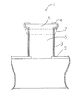
図1は本発明の混注部材1の概略図で、図2は図1の混注部材1の締付部材7を上にスライドさせ、栓体5を締付けた時の混注部材1の概略図である。
混注部材1は管状の本体2の天面に突設された管状の胴部3に弾性を有しかつ少なくとも天面にスリット6を形成した栓体5を装着し、前記胴部3下部の外周にリング状の締付部材7を装着する事により構成されている。
胴部3は下部から上部に向けて若干であるが大径になるように形成され、外周に装着した締付部材7を、胴部3の下部から上部にスライドさせる時に胴部3の上部は、締付部材7の内周面に外周から締付けられ、ひいては胴部3の内部に装着された栓体5のスリット6も胴部3の外周からの圧力によって締付けられるように形成されている。
また図1において4は天面の中央部が開口された筒状のキャップで、栓体5の天上側面から胴部3の外周に亘って装着されている。
前記締付部材7の形状は図1に示したものに限定されず、要するに胴部3の外周から栓体5を締付けることのできる形状であれば何でも良い。
【0006】
穿刺部材を混注部材1に穿刺する場合、キャップ4の開口部に露出した栓体5天面のスリット6に前記穿刺部材を穿刺して、その先端を栓体5の底面を越えるまで貫通させる。
穿刺部材の後方に装着された容器内に封入されている薬剤を投与した後、穿刺部材を栓体5より引き抜いて、胴部3の外周に設けられた締付部材7を上方向にスライドさせる事により締付部材7の外周から加圧して、胴部3を介して栓体5のスリット6を締付ける事により、穿刺部材を引き抜いた跡を完全に締付けて液漏れを防ぐ事ができる。
また、穿刺部材を穿刺し、容器に入れた薬剤等を継続的に投与する場合は、前記穿刺部材を穿刺したまま、締付部材7を上方向にスライドさせて前記と同様に栓体5のスリット6を締付ける事により穿刺部材を締付け、穿刺部材が抜け落ちないように、さらに穿刺部材とスリット6の間から液漏れがないようにする事ができる。
【0007】
図3はその他の発明の実施例を示す混注部材11の概略図で、図4は図3の混注部材11の締付部材17を上から押す事により、栓体5を締付けた時の混注部材11の概略図である。
混注部材11は管状の本体12の天面に突設された管状の胴部13に弾性を有し、かつ少なくとも天面にスリット6を形成した栓体5を装着し、前記栓体5の天上側面から胴部13の外周に亘って、天面の中央が開口された筒状の締付部材17を装着する事により構成されている。締付部材17は前記混注部材1のキャップ4の役割も果す。
前記胴部13と締付部材17の接触部には係合部が形成されている。
図3の実施例では、係合部は凸部と凹部の組み合わせにより構成される。
さらに詳述すれば胴部13の上部外周に2本の凹部18aと凹部18bが形成されており、溝の深さは凹部18aの方が深く、凹部18bが浅く形成されている。それに伴い締付部材17の前記胴部13と接する内周面には、前記凹部18aと係合する凸部19が形成されている。
前記係合部の形状は図3に示したものに限定されず、環状、縦線状、点状、螺旋状の凹凸とし、凹凸に段差等を付ける事により締付部材17を押したり、または螺旋状を捩じったりして、栓体5を締付けるようにしても良い。
要するに係合部の位置をスライドさせる事により、胴部13の外周から栓体5を締付ける事のできる形状であれば何でも良い。
【0008】
前記と同様にスリット6に穿刺部材を穿刺し、薬剤投与後穿刺部材を引き抜く。締付部材17を上から押す事により、図4のように締付部材17の凸部19が胴部13の凹部18aから凹部18bに移動する。凹部18bは凹部18aに比べて溝の深さが浅いので、凸部19が元の凹部18aの深さ位置に納まろうとする反動により、凹部18bは凹部18aより凸部19の外周から締付けようとする圧力をより多く受ける事になる。これにより胴部13の凹部18bが、外周からの圧力により締付けられ、さらに栓体5のスリット6も締付けられる事により、穿刺部材を引き抜いた跡を完全に締付けて液漏れを防ぐ事ができる。
また、穿刺部材を穿刺し、容器に入れた薬剤等を継続的に投与する場合は、前記穿刺部材を穿刺したまま、締付部材17を上から押して前記と同様に、栓体5のスリット6を締付ける事により、穿刺部材を締付け穿刺部材が抜け落ちないように、さらに穿刺部材とスリット6の間から液漏れがないようにする事ができる。
【0009】
図5はその他の発明の実施例を示す混注部材21の概略図で、図6は図5の混注部材21の平面図である。図7は図5の混注部材21で締付部材27をスライドさせ、栓体5を締付けた時の混注部材21の概略図である。図8は図7の混注部材21の平面図である。
混注部材21は管状の本体22の天面に突設された管状の胴部23に弾性を有し、かつ少なくとも天面にスリット6を形成した栓体5を装着し、前記胴部23の外周には少なくとも胴部23の縦方向に対して、垂直方向に幅が変化する二つの壁面を備えた締付部材27を装着する事により構成されている。
締付部材27は中央の幅が狭く、中央の両側の幅が次第に広くなるように内側に湾曲して形成されている。胴部23は外周に装着した締付部材27を胴部23の縦方向に対して垂直方向にスライドさせる時に、該胴部23の外周は締付部材27中央の幅の狭い二つの壁面により締付けられ、ひいては胴部23の内部に装着された栓体5のスリット6も締付部材27の幅の狭い二つの壁面からの圧力によって締付けられる。
締付部材27の形状は図5に示したものに限定されず、要するに胴部23の縦方向に対して垂直方向にスライドさせる時に、胴部23の外周から栓体5を締付けることのできる形状であれば何でも良い。
【0010】
前記と同様にスリット6に穿刺部材を穿刺し、薬剤投与後穿刺部を引き抜く。胴部23の外周に装着した締付部材27を胴部23の縦方向に対して垂直方向にスライドさせ、胴部23の外周を締付部材27中央の幅の狭い二つの壁面により締付ける事により、栓体5のスリット6が締付けられ、穿刺部材を引き抜いた跡を完全に締付けて液漏れを防ぐ事ができる。
また、穿刺部材を穿刺し、容器に入れた薬剤等を継続的に投与する場合は、前記穿刺部材を穿刺したまま、前記と同様に栓体5のスリット6が締付けて穿刺部材を締付け、穿刺部材が抜け落ちないように、さらに穿刺部材とスリット6の間から液漏れがないようにする事ができる。
【0011】
図1から図7の混注部材1、11、21は本体2、12、22の長さ方向に対して胴部3、13、23を垂直に突設したT字状の混注部材1、11、21であるが、本発明の混注部材はT字状のものに限定されるものではなく、本体2、12、22の長さ方向に対して胴部3、13、23斜めに突設したY字状の混注部材、本体2、12、22の長さ方向に対し胴部3、13、23の端部に突設したストレート状の混注部材も含む。
【0012】
以上は混注部材の例について説明したが前記混注部材1、11、21は本体2、12、22を胴部3、13、23の下方にほぼ垂直に延設して、薬剤の封入された袋状の容器本体の上部に装着すれば医薬容器の口部に転用することができる。また容器本体に前記口部が一体成形されたプラスチック製の医薬容器にも口部(既に本体2、12、22と胴部3、13、23を備える)に前記栓体5と締付部材7、17、27を使用してこれらの医薬容器の口部に転用することができる。また容器本体がガラス製の医薬容器であっても容器本体の上部に装着される口部のうち少なくとも胴部が締付部材7、17、27を装着して締付けることのできるプラスチック製のものであれば前記栓体5と締付部材7、17、27を使用してこれらの医薬容器の口部に転用することができる。
【0013】
【発明の作用効果】
胴部(3、13、23)にスリット(6)を形成した栓体(5)を装着し、前記胴部(3、13、23)の外周に締付部材(7、17、27)を装着し、該締付部材(7、17、27)をスライドさせ、胴部(3、13、23)及び栓体(5)を外から締め付ける事ができるように形成した事により、穿刺部材を引き抜いた跡を完全に締付けて液漏れを防ぐ事ができ、また穿刺部材を穿刺したまま穿刺部材が抜け落ちないように、さらに穿刺部材とスリットの間から液漏れがないようにする事ができる。
【図面の簡単な説明】
【図1】本発明の混注部材1の概略図
【図2】図1の混注部材1の締付部材7を上にスライドさせ、栓体5を締付けた時の混注部材1の概略図
【図3】その他の発明の実施例を示す混注部材11の概略図
【図4】図3の混注部材11の締付部材17を上から押す事により、栓体5を締付けた時の混注部材11の概略図
【図5】その他の発明の実施例を示す混注部材21の概略図
【図6】図5の混注部材21の平面図
【図7】図5の混注部材21で締付部材27をスライドさせ、栓体5を締付けた時の混注部材21の概略図
【図8】図7の混注部材21の平面図
【符号の説明】
1、11、21 混注部材
2、12、22 本体
3、13、23 胴部
4、24 キャップ
5 栓体
6 スリット
7、17、27 締付部材
18a、18b 凹部
19 凸部[0001]
BACKGROUND OF THE INVENTION
The present invention is, for example, mounted on a pharmaceutical container enclosing a mixed injection member disposed in the middle of a medical device such as an infusion set, a blood collection set, a transfusion set, an extracorporeal circuit, and a medicine (infusion solution, physiological saline solution, blood preservation solution, etc.). This is a mixed injection member placed in the middle of the mouth part and the tube connected to the pharmaceutical container, and is used when mixing or collecting a drug in these medical instruments and pharmaceutical containers, or collecting or injecting blood The present invention relates to improvement of a mixed injection member and a mouth portion.
[0002]
[Problems to be solved by the invention]
When performing blood transfusion treatments that introduce blood into the patient's body, blood sampling tests that extract blood outside the body, fluid treatments that introduce drugs into the patient's body, or extracorporeal circulation treatments that temporarily remove blood from the patient's body, etc. And devices for injecting and collecting drugs into patients (eg, blood transfusion set, infusion set, extracorporeal circuit, blood collection set, etc.).
A number of components are installed in the middle of the lines that make up a transfusion set, infusion set, extracorporeal circuit, blood collection set, etc., but mixed injection members add blood or collect blood for testing. In addition, it plays an important role such as drug addition and emergency drug administration.
[0003]
Normally, these co-infusion members are fitted with a plug body on a body portion protruding from a tubular main body, and a cap with an open center is attached to the plug body.
In use, a needle with a sharp tip is punctured on the top surface of the plug exposed at the central opening of the cap, and a medicine or blood sealed in a container attached behind the needle is injected or emptied. Blood is collected in the container.
The needle used is often a metal needle with a sharp tip, but there is a greater risk that the operator touches the tip of the metal needle and is infected not only with trauma but also with infectious diseases. Instead of a simple metal needle, a method of using a puncture member having a rounded shape at the tip has been devised.
Attempting to make the piercing member easier to pierce by making a slit in the top surface of the plug body to puncture a mixed injection member with a puncture member having a rounded tip (hereinafter abbreviated as “puncture member”). There is.
By inserting a slit, puncture can be triggered and puncture resistance is lowered and puncture is facilitated, but the tip is rounded and the slit expands to enlarge the puncture mark, and blood and medicine are extracted after the puncture member is pulled out. There is a risk of liquid leakage. Moreover, there is a possibility that the puncture member can be easily removed by inserting the slit.
Therefore, as a result of intensive studies to solve the above problems, the present inventor has reached the following invention.
[0004]
[Means for Solving the Problems]
[1] The present invention provides:
A tubular body (3) protruding from the top surface of the tubular body (2) is fitted with a plug (5) having elasticity and at least a slit (6) formed on the top surface,
A ring-shaped tightening member (7) is mounted on the outer periphery of the lower portion of the body (3),
The trunk (3) is formed to have a slightly larger diameter from the lower part to the upper part,
When the fastening member (7) is slid from the lower part of the body part (3) to the upper part, the upper part of the body part (3) is fastened from the outer periphery to the inner peripheral surface of the fastening member (7). ,
Provided is a co-infusion member (1) formed so that the slit (6) of the plug (5) mounted in the body (3) is also tightened by pressure from the outer periphery of the body (3). .
[2] The present invention provides:
The tubular body (13) projecting from the top surface of the tubular body (12) is fitted with a
A cylindrical fastening member (17) having an opening at the center of the top surface is mounted from the top side surface of the plug body (5) to the outer periphery of the trunk portion (13).
A deep recess (18a) and a shallow recess (18b) having a groove are formed on the upper outer periphery of the body (13) sequentially from the top.
A convex part (19) that engages with the deep concave part (18a) of the groove is formed on the inner peripheral surface of the fastening member (17) that is in contact with the body part (13).
By pressing the tightening member (17) from above, the convex portion (19) of the tightening member (17) is changed from a deep concave portion (18a) to a shallow concave portion (18b) of the trunk portion (13). )
The shallow recess (18b) in the groove of the body (13) is tightened by the pressure from the outer periphery by the tightening member (17), and the slit (6) of the plug (5) is also tightened. The formed mixed injection member (11) is provided.
[3] The present invention
A
A fastening member (27) provided with two wall surfaces whose width changes in the vertical direction at least with respect to the longitudinal direction of the trunk portion (23) is attached to the outer periphery of the trunk portion (23),
The tightening member (27) has a narrow central width and is formed to be curved inward so that the width on both sides of the central portion is gradually increased.
When the tightening member (27) mounted on the outer periphery of the body (23) is slid in a direction perpendicular to the longitudinal direction of the body (23), the outer periphery of the body (23) is a tightening member. (27) It is tightened by two narrow walls in the center,
The mixed injection member formed so that the slit (6) of the plug (5) mounted in the body (23) is also tightened by the pressure from the two narrow wall surfaces of the tightening member (27). (21) is provided.
[4] The present invention provides a medical device having the co-infusion member (1, 11, 21) according to any one of [1] to [3] .
[5] The present invention provides:
A tubular body (3) protruding from the top surface of the tubular body (2) is fitted with a plug (5) having elasticity and at least a slit (6) formed on the top surface,
A ring-shaped tightening member (7) is mounted on the outer periphery of the lower portion of the body (3),
The trunk (3) is formed to have a slightly larger diameter from the lower part to the upper part,
When the fastening member (7) is slid from the lower part of the body part (3) to the upper part, the upper part of the body part (3) is fastened from the outer periphery to the inner peripheral surface of the fastening member (7). ,
The slit (6) of the plug (5) mounted inside the body (3) also provides a mouth formed so as to be tightened by pressure from the outer periphery of the body (3) .
[6] The present invention provides:
A tubular body (13) is fitted with a
A cylindrical fastening member (17) having an opening at the center of the top surface is mounted from the top side surface of the plug body (5) to the outer periphery of the trunk portion (13).
A deep recess (18a) and a shallow recess (18b) having a groove are formed on the upper outer periphery of the body (13) sequentially from the top.
A convex part (19) that engages with the deep concave part (18a) of the groove is formed on the inner peripheral surface of the fastening member (17) that is in contact with the body part (13).
By pressing the tightening member (17) from above, the convex portion (19) of the tightening member (17) is changed from the deep concave portion (18a) of the groove of the trunk portion (13 ) to the shallow concave portion ( 18b)
The shallow recess (18b) in the groove of the body (13) is tightened by the pressure from the outer periphery by the tightening member (17), and the slit (6) of the plug (5) is also tightened. Provide the formed mouth .
[7] The present invention provides:
The tubular body (23) is fitted with a
A fastening member (27) provided with two wall surfaces whose width changes in the vertical direction at least with respect to the longitudinal direction of the trunk portion (23) is attached to the outer periphery of the trunk portion (23),
The tightening member (27) has a narrow central width and is formed to be curved inward so that the width on both sides of the central portion is gradually increased.
When the tightening member (27) mounted on the outer periphery of the body (23) is slid in a direction perpendicular to the longitudinal direction of the body (23), the outer periphery of the body (23) is a tightening member. (27) It is tightened by two narrow walls in the center,
An opening formed so that the slit (6) of the plug (5) mounted in the body (23) is also tightened by pressure from two narrow walls of the tightening member (27). I will provide a.
[8] The present invention provides a pharmaceutical container having the mixed injection member according to any one of [1] to [3] and / or the mouth portion according to any one of [5] to [7] .
[0005]
DETAILED DESCRIPTION OF THE INVENTION
Hereinafter, an example in the case of performing mixed injection of medicines on the mixed injection member will be described.
FIG. 1 is a schematic view of a mixed injection member 1 of the present invention, and FIG. 2 is a schematic view of the mixed injection member 1 when a fastening member 7 of the mixed injection member 1 of FIG. .
The mixed injection member 1 has a tubular body 3 protruding from the top surface of a tubular body 2 and is fitted with a
The body part 3 is formed to have a slightly larger diameter from the lower part to the upper part. When the fastening member 7 mounted on the outer periphery is slid from the lower part to the upper part of the body part 3, the upper part of the body part 3 is The
In FIG. 1,
The shape of the tightening member 7 is not limited to that shown in FIG. 1. In short, any shape can be used as long as the
[0006]
When the piercing member is pierced into the mixed injection member 1, the piercing member is pierced into the
After administering the medicine enclosed in the container mounted behind the puncture member, the puncture member is pulled out from the
When the puncture member is punctured and the medicine or the like placed in the container is continuously administered, the fastening member 7 is slid upward while the puncture member is punctured, and the
[0007]
FIG. 3 is a schematic view of the co-infusion member 11 showing another embodiment of the invention. FIG. 4 is a co-infusion member when the
The mixed injection member 11 has a
An engaging portion is formed at a contact portion between the
In the embodiment of FIG. 3, the engaging portion is constituted by a combination of a convex portion and a concave portion.
More specifically, two
The shape of the engaging portion is not limited to that shown in FIG. 3, and the ring-shaped, vertical line-shaped, dot-shaped, and spiral-shaped unevenness is formed, and the tightening
In short, any shape can be used as long as the
[0008]
In the same manner as described above, a puncture member is punctured into the
When the puncture member is punctured and the medicine or the like placed in the container is continuously administered, the
[0009]
FIG. 5 is a schematic view of a
The
The
The shape of the tightening
[0010]
In the same manner as described above, a puncture member is punctured into the
When the puncture member is punctured and the medicine or the like placed in the container is continuously administered, the
[0011]
The
[0012]
The mixed injection member has been described above. However, the
[0013]
[Effects of the invention]
A stopper (5) having a slit (6) is mounted on the body (3, 13, 23), and a tightening member (7, 17, 27) is attached to the outer periphery of the body (3, 13, 23). The puncture member is formed by mounting and sliding the fastening members (7, 17, 27) so that the body (3, 13, 23) and the plug (5) can be tightened from the outside. The pulled trace can be completely tightened to prevent liquid leakage, and the liquid can be prevented from leaking between the puncture member and the slit so that the puncture member does not fall out while the puncture member is punctured.
[Brief description of the drawings]
FIG. 1 is a schematic view of a mixed injection member 1 according to the present invention. FIG. 2 is a schematic view of the mixed injection member 1 when a
1, 11, 21
Claims (8)
前記胴部(3)下部の外周にリング状の締付部材(7)を装着し、A ring-shaped tightening member (7) is mounted on the outer periphery of the lower portion of the body (3),
前記胴部(3)は下部から上部に向けて若干大径となるように形成され、The trunk (3) is formed to have a slightly larger diameter from the lower part to the upper part,
前記締付部材(7)を、前記胴部(3)の下部から上部にスライドさせる時に、前記胴部(3)の上部は、前記締付部材(7)の内周面に外周から締付けられ、When the fastening member (7) is slid from the lower part of the body part (3) to the upper part, the upper part of the body part (3) is fastened from the outer periphery to the inner peripheral surface of the fastening member (7). ,
前記胴部(3)の内部に装着された前記栓体(5)のスリット(6)も前記胴部(3)の外周からの圧力によって締付けられるように形成した、ことを特徴とする混注部材(1)。The co-infusion member, wherein the slit (6) of the plug (5) mounted inside the body (3) is also formed to be tightened by pressure from the outer periphery of the body (3). (1).
前記栓体(5)の天上側面から前記胴部(13)の外周に亘って、天面の中央が開口された筒状の締付部材(17)を装着し、A cylindrical fastening member (17) having an opening at the center of the top surface is mounted from the top side surface of the plug body (5) to the outer periphery of the trunk portion (13).
前記胴部(13)の上部外周に、上から順次、溝の深い凹部(18a)と溝の浅い凹部(18b)を形成し、A deep recess (18a) and a shallow recess (18b) having a groove are formed on the upper outer periphery of the body (13) sequentially from the top.
前記締付部材(17)の前記胴部(13)と接する内周面に、前記溝の深い凹部(18a)と係合する凸部(19)を形成し、A convex part (19) that engages with the deep concave part (18a) of the groove is formed on the inner peripheral surface of the fastening member (17) that is in contact with the body part (13).
前記締付部材(17)を上から押すことより、当該締付部材(17)の凸部(19)が、前記胴部(13)の溝の深い凹部(18a)から溝の浅い凹部(18b)に移動し、By pressing the tightening member (17) from above, the convex portion (19) of the tightening member (17) is changed from a deep concave portion (18a) to a shallow concave portion (18b) of the trunk portion (13). )
前記胴部(13)の溝の浅い凹部(18b)が、前記締付部材(17)により、外周からの圧力により締付けられ、さらに前記栓体(5)のスリット(6)も締付けられるように形成した、ことを特徴とする混注部材(11)。The shallow recess (18b) in the groove of the body (13) is tightened by the pressure from the outer periphery by the tightening member (17), and the slit (6) of the plug (5) is also tightened. A mixed injection member (11) characterized by being formed.
前記胴部(23)の外周には少なくとも当該胴部(23)の縦方向に対して、垂直方向に幅が変化する二つの壁面を備えた締付部材(27)を装着し、A fastening member (27) provided with two wall surfaces whose width changes in the vertical direction at least with respect to the longitudinal direction of the trunk portion (23) is attached to the outer periphery of the trunk portion (23),
当該締付部材(27)は中央の幅が狭く、中央の両側の幅が次第に広くなるように内側に湾曲して形成し、The tightening member (27) has a narrow central width and is formed to be curved inward so that the width on both sides of the central portion is gradually increased.
前記胴部(23)は外周に装着した前記締付部材(27)を当該胴部(23)の縦方向に対して垂直方向にスライドさせる時に、当該胴部(23)の外周は締付部材(27)中央の幅の狭い二つの壁面により締付けられ、When the tightening member (27) mounted on the outer periphery of the body (23) is slid in a direction perpendicular to the longitudinal direction of the body (23), the outer periphery of the body (23) is a tightening member. (27) It is tightened by two narrow walls in the center,
当該胴部(23)の内部に装着された前記栓体(5)のスリット(6)も前記締付部材(27)の幅の狭い二つの壁面からの圧力によって締付けられように形成した、ことを特徴とする混注部材(21)。The slit (6) of the plug (5) mounted inside the body (23) is also formed so as to be tightened by pressure from two narrow wall surfaces of the tightening member (27). Mixed injection member (21) characterized by the above.
前記胴部(3)下部の外周にリング状の締付部材(7)を装着し、A ring-shaped tightening member (7) is mounted on the outer periphery of the lower portion of the body (3),
前記胴部(3)は下部から上部に向けて若干大径となるように形成され、The trunk (3) is formed to have a slightly larger diameter from the lower part to the upper part,
前記締付部材(7)を、前記胴部(3)の下部から上部にスライドさせる時に、前記胴部(3)の上部は、前記締付部材(7)の内周面に外周から締付けられ、When the fastening member (7) is slid from the lower part of the body part (3) to the upper part, the upper part of the body part (3) is fastened from the outer periphery to the inner peripheral surface of the fastening member (7). ,
前記胴部(3)の内部に装着された前記栓体(5)のスリット(6)も前記胴部(3)の外周からの圧力によって締付けられるように形成した、ことを特徴とする口部。The mouth portion characterized in that the slit (6) of the plug (5) mounted inside the barrel portion (3) is also formed to be tightened by pressure from the outer periphery of the barrel portion (3). .
前記栓体(5)の天上側面から前記胴部(13)の外周に亘って、天面の中央が開口された筒状の締付部材(17)を装着し、
前記胴部(13)の上部外周に、上から順次、溝の深い凹部(18a)と溝の浅い凹部(18b)を形成し、
前記締付部材(17)の前記胴部(13)と接する内周面に、前記溝の深い凹部(18a)と係合する凸部(19)を形成し、
前記締付部材(17)を上から押すことより、当該締付部材(17)の凸部(19)が、前記胴部(13)の溝の深い凹部(18a)から溝の浅い凹部(18b)に移動し、
前記胴部(13)の溝の浅い凹部(18b)が、前記締付部材(17)により、外周からの圧力により締付けられ、さらに前記栓体(5)のスリット(6)も締付けられるように形成した、ことを特徴とする口部。 A tubular body (13) is fitted with a plug 5 having elasticity and at least a slit (6) formed on the top surface,
A cylindrical fastening member (17) having an opening at the center of the top surface is mounted from the top side surface of the plug body (5) to the outer periphery of the trunk portion (13).
A deep recess (18a) and a shallow recess (18b) having a groove are formed on the upper outer periphery of the body (13) sequentially from the top.
A convex part (19) that engages with the deep concave part (18a) of the groove is formed on the inner peripheral surface of the fastening member (17) that is in contact with the body part (13).
By pressing the tightening member (17) from above, the convex portion (19) of the tightening member (17) is changed from the deep concave portion (18a) of the groove of the trunk portion (13 ) to the shallow concave portion ( 18b)
The shallow recess (18b) in the groove of the body (13) is tightened by the pressure from the outer periphery by the tightening member (17), and the slit (6) of the plug (5) is also tightened. A mouth characterized by being formed.
前記胴部(23)の外周には少なくとも当該胴部(23)の縦方向に対して、垂直方向に幅が変化する二つの壁面を備えた締付部材(27)を装着し、A fastening member (27) provided with two wall surfaces whose width changes in the vertical direction at least with respect to the longitudinal direction of the trunk portion (23) is attached to the outer periphery of the trunk portion (23),
当該締付部材(27)は中央の幅が狭く、中央の両側の幅が次第に広くなるように内側に湾曲して形成し、The tightening member (27) has a narrow central width and is formed to be curved inward so that the width on both sides of the central portion is gradually increased.
前記胴部(23)は外周に装着した前記締付部材(27)を当該胴部(23)の縦方向に対して垂直方向にスライドさせる時に、当該胴部(23)の外周は締付部材(27)中央の幅の狭い二つの壁面により締付けられ、When the tightening member (27) mounted on the outer periphery of the body (23) is slid in a direction perpendicular to the longitudinal direction of the body (23), the outer periphery of the body (23) is a tightening member. (27) It is tightened by two narrow walls in the center,
当該胴部(23)の内部に装着された前記栓体(5)のスリット(6)も前記締付部材(27)の幅の狭い二つの壁面からの圧力によって締付けられように形成した、ことを特徴とする口部。The slit (6) of the plug (5) mounted inside the body (23) is also formed so as to be tightened by pressure from two narrow wall surfaces of the tightening member (27). A mouth characterized by.
Priority Applications (1)
| Application Number | Priority Date | Filing Date | Title |
|---|---|---|---|
| JP27447998A JP4216926B2 (en) | 1998-09-29 | 1998-09-29 | Mixed injection member and medical device, mouth and medicine container |
Applications Claiming Priority (1)
| Application Number | Priority Date | Filing Date | Title |
|---|---|---|---|
| JP27447998A JP4216926B2 (en) | 1998-09-29 | 1998-09-29 | Mixed injection member and medical device, mouth and medicine container |
Publications (2)
| Publication Number | Publication Date |
|---|---|
| JP2000102593A JP2000102593A (en) | 2000-04-11 |
| JP4216926B2 true JP4216926B2 (en) | 2009-01-28 |
Family
ID=17542273
Family Applications (1)
| Application Number | Title | Priority Date | Filing Date |
|---|---|---|---|
| JP27447998A Expired - Lifetime JP4216926B2 (en) | 1998-09-29 | 1998-09-29 | Mixed injection member and medical device, mouth and medicine container |
Country Status (1)
| Country | Link |
|---|---|
| JP (1) | JP4216926B2 (en) |
Families Citing this family (4)
| Publication number | Priority date | Publication date | Assignee | Title |
|---|---|---|---|---|
| JP4016313B2 (en) * | 2000-09-26 | 2007-12-05 | 株式会社ジェイ・エム・エス | Medical mixed injection port |
| JP4477216B2 (en) * | 2000-10-26 | 2010-06-09 | 株式会社大塚製薬工場 | Cap, method of manufacturing the same, and drug container using the cap |
| JP2004237134A (en) * | 2004-05-27 | 2004-08-26 | Jms Co Ltd | Mixed injection port for medical treatment |
| JP2004237133A (en) * | 2004-05-27 | 2004-08-26 | Jms Co Ltd | Mixed injection port for medical treatment |
-
1998
- 1998-09-29 JP JP27447998A patent/JP4216926B2/en not_active Expired - Lifetime
Also Published As
| Publication number | Publication date |
|---|---|
| JP2000102593A (en) | 2000-04-11 |
Similar Documents
| Publication | Publication Date | Title |
|---|---|---|
| US5360407A (en) | Implantable dual access port with tactile ridge for position sensing | |
| JP2540026B2 (en) | Chemical access assembly for vials and ampoules | |
| JP2535310B2 (en) | Drug release system | |
| US5147329A (en) | Intravenous access devices | |
| JP2988661B2 (en) | Fluid transfer device for accessing fluid from vials and ampules and method for transferring fluid using the device | |
| US5466219A (en) | Blood aspiration assembly components and blunt needle aspirators | |
| RU2397784C2 (en) | System of adaptor device | |
| AU694029B2 (en) | Needleless vial access device | |
| EP1396250B1 (en) | Transfer needle assembly | |
| US3332418A (en) | Injection site for venoclysis apparatus | |
| JP4357611B2 (en) | Fluid transfer device | |
| KR101095961B1 (en) | Safety socket enabling to prevent medicine accident and infusion bag kit having the socket | |
| JP2019536535A (en) | Liquid transfer device with integrated telescopic vial adapter for use with infusion fluid containers and individual injection vials | |
| US5102408A (en) | Fluid mixing reservoir for use in medical procedures | |
| JPS6072561A (en) | Two-drug component syringe having vein display capacity | |
| US2453591A (en) | Hypodermic syringe | |
| JP7386851B2 (en) | Syringe assembly and adapter parts | |
| JP4216926B2 (en) | Mixed injection member and medical device, mouth and medicine container | |
| JP3763999B2 (en) | Puncture member and syringe with puncture member | |
| JP3294537B2 (en) | Fluid transfer device for accessing fluid from vials and ampules and method for transferring fluid using the device | |
| JP3934143B2 (en) | Mixed injection member, medical device, mouth and medicine container | |
| JP4382901B2 (en) | Mixed injection member and mouth, medical device and pharmaceutical container | |
| KR102510416B1 (en) | Connecting Socket for Medicine Bottle | |
| JP4176888B2 (en) | Mixed injection member and medical device, mouth and medicine container | |
| JP2003290362A (en) | Side injection tube |
Legal Events
| Date | Code | Title | Description |
|---|---|---|---|
| A621 | Written request for application examination |
Free format text: JAPANESE INTERMEDIATE CODE: A621 Effective date: 20050630 |
|
| A977 | Report on retrieval |
Free format text: JAPANESE INTERMEDIATE CODE: A971007 Effective date: 20080123 |
|
| A131 | Notification of reasons for refusal |
Free format text: JAPANESE INTERMEDIATE CODE: A131 Effective date: 20080311 |
|
| A521 | Written amendment |
Free format text: JAPANESE INTERMEDIATE CODE: A523 Effective date: 20080430 |
|
| TRDD | Decision of grant or rejection written | ||
| A01 | Written decision to grant a patent or to grant a registration (utility model) |
Free format text: JAPANESE INTERMEDIATE CODE: A01 Effective date: 20081104 |
|
| A01 | Written decision to grant a patent or to grant a registration (utility model) |
Free format text: JAPANESE INTERMEDIATE CODE: A01 |
|
| A61 | First payment of annual fees (during grant procedure) |
Free format text: JAPANESE INTERMEDIATE CODE: A61 Effective date: 20081107 |
|
| R150 | Certificate of patent or registration of utility model |
Free format text: JAPANESE INTERMEDIATE CODE: R150 |
|
| FPAY | Renewal fee payment (event date is renewal date of database) |
Free format text: PAYMENT UNTIL: 20111114 Year of fee payment: 3 |
|
| S531 | Written request for registration of change of domicile |
Free format text: JAPANESE INTERMEDIATE CODE: R313531 |
|
| FPAY | Renewal fee payment (event date is renewal date of database) |
Free format text: PAYMENT UNTIL: 20111114 Year of fee payment: 3 |
|
| R350 | Written notification of registration of transfer |
Free format text: JAPANESE INTERMEDIATE CODE: R350 |
|
| FPAY | Renewal fee payment (event date is renewal date of database) |
Free format text: PAYMENT UNTIL: 20111114 Year of fee payment: 3 |
|
| FPAY | Renewal fee payment (event date is renewal date of database) |
Free format text: PAYMENT UNTIL: 20121114 Year of fee payment: 4 |
|
| FPAY | Renewal fee payment (event date is renewal date of database) |
Free format text: PAYMENT UNTIL: 20131114 Year of fee payment: 5 |
|
| R250 | Receipt of annual fees |
Free format text: JAPANESE INTERMEDIATE CODE: R250 |
|
| R250 | Receipt of annual fees |
Free format text: JAPANESE INTERMEDIATE CODE: R250 |
|
| R250 | Receipt of annual fees |
Free format text: JAPANESE INTERMEDIATE CODE: R250 |
|
| EXPY | Cancellation because of completion of term |