JP2004237134A - Mixed injection port for medical treatment - Google Patents
Mixed injection port for medical treatment Download PDFInfo
- Publication number
- JP2004237134A JP2004237134A JP2004157688A JP2004157688A JP2004237134A JP 2004237134 A JP2004237134 A JP 2004237134A JP 2004157688 A JP2004157688 A JP 2004157688A JP 2004157688 A JP2004157688 A JP 2004157688A JP 2004237134 A JP2004237134 A JP 2004237134A
- Authority
- JP
- Japan
- Prior art keywords
- valve
- cover
- medical
- infusion port
- thickness
- Prior art date
- Legal status (The legal status is an assumption and is not a legal conclusion. Google has not performed a legal analysis and makes no representation as to the accuracy of the status listed.)
- Pending
Links
Images


Abstract
Description
本発明は送液路外部から液を混注したり、逆に送液路内部から液を採取したりする際に、その操作を容易にかつ確実に行うために医療器具に装着される医療用混注ポートに関する。 The present invention relates to a medical co-infusion that is attached to a medical device in order to easily and reliably perform an operation when a liquid is co-injected from the outside of a liquid supply path or when a liquid is collected from the inside of a liquid supply path. About the port.
患者に輸液や輸血を行う場合に種類の異なる薬液を混注したり、送液路に流れる液をサンプル採取するため、主送液路に側注ラインを設けることが必要である場合が多い。このようなときに、従来は輸液セットの送液路にゴム製の穿刺用混注口(栓)を設けたものを使用し、混注口に注射針等を穿刺して混注していた。 When performing infusion or blood transfusion to a patient, it is often necessary to provide a side injection line in the main infusion path in order to mix and inject different types of liquid medicines or to sample liquid flowing in the infusion path. In such a case, conventionally, an infusion set provided with a rubber puncture co-injection port (plug) in the liquid feed path has been used, and the co-injection port has been punctured with an injection needle or the like for co-injection.
しかし、このような方法では混注口の所定の穿刺部位以外から針を穿刺すると、その箇所から液漏れを起こしたり、あるいは作業ミス等により注射針を汚染したりする問題があった。そこで、混注口に挿入するルアー等(以下、「挿入体」という。)を混注口に固定・保持するために、最近では挿入体を保持できる混注口が考えられている。例えば、シリンジ先端の雄ルアー部を混注ポートに挿入すると、ルアーの押し込みによって弁が開放され液が注入できるようになり、混注口からルアーを抜くと弁が独りでに閉じるというような弁を装着した混注口である。 However, in such a method, when a needle is punctured from a site other than a predetermined puncture site of the co-infusion port, there is a problem that a liquid leaks from the site or a needle is contaminated due to an operation mistake or the like. Therefore, in order to fix and hold a luer or the like (hereinafter, referred to as an “insert”) to be inserted into the co-injection port, a co-injection port capable of holding the insert has been recently considered. For example, when the male luer at the tip of the syringe is inserted into the co-injection port, the valve is opened and the liquid can be injected by pushing the lure, and when the lure is pulled out from the co-injection port, the co-injection is equipped with a valve that closes by itself. Mouth.
しかし、この混注口はルアー(挿入体)の弁への挿入時(弁開放)、抜去時(弁閉止)に関係なく、ルアーを混注口に保持する必要性があるため、以下のような様々な問題を有している。すなわち、第1に混注口のルアー受け部を深くする必要があり、かかる形状では弁からこぼれた液を除去できにくいため、不潔になり易い。また、ルアー受け部の深い混注口では弁にルアーが十分に挿入できていない状態で混注し始める可能性がある。その場合、混注する薬液が少量であると有効な量の薬液投与ができないことになる。第2に弁の構造が複雑になり、コストアップ要因となる。また、複雑な構造になるほど弁は故障し易くなる。 However, this co-injection port needs to hold the lure in the co-injection port regardless of whether the lure (insert) is inserted into the valve (valve open) or removed (valve closed). Problems. That is, firstly, it is necessary to deepen the lure receiving portion of the co-injection port, and in such a shape, it is difficult to remove the liquid spilled from the valve, so that it becomes easy to be dirty. In addition, in the co-injection port having a deep lure receiving portion, co-injection may be started in a state where the lure has not been sufficiently inserted into the valve. In this case, if the co-injected drug solution is small, it is impossible to administer an effective amount of the drug solution. Second, the structure of the valve becomes complicated, which causes an increase in cost. Also, the more complicated the structure, the more likely the valve will fail.
一方、従来のような簡単な(例えば、ディスク状の弾性部材にスリットを設けただけの弁を装着した)混注口では、シリンジのルアーを混注口に挿入しにくく、また挿入できたとしてもシリンジを混注口に確実に保持することが困難であった。従来、ディスク状の弁は弾性の大きい材料で形成され、肉厚の本体部に単に切れ込みが形成された簡単な構造であるために挿入時の抵抗が大きく、保持するときの弁の変形も大きいためである。しかし、挿入の際の抵抗を減少させるために、弁の弾性部材の肉厚を減らしたり、弾性の小さい材料を使用すると、今度は弁の逆止効果が低下して液漏れする恐れがある。 On the other hand, in a conventional co-injection port (for example, a disc-shaped elastic member provided with a valve having only a slit provided), it is difficult to insert the lure of the syringe into the co-injection port. It was difficult to reliably hold in the mixed injection port. Conventionally, a disc-shaped valve is formed of a material having high elasticity and has a simple structure in which a notch is simply formed in a thick body, so that the resistance at the time of insertion is large and the deformation of the valve at the time of holding is large. That's why. However, if the thickness of the elastic member of the valve is reduced or a material having low elasticity is used in order to reduce the resistance at the time of insertion, the check effect of the valve may be reduced and liquid leakage may occur.
そこで、かかる問題点を解消すべく、中央部に挿入孔の形成されたディスク状の弁と、当該弁の裏側面の中央部を残して周縁下部を担持する台座と、当該弁の表側面の中央部を残し少なくとも弁の周縁上部を覆う弁を拘持するカバーとを備え、挿入体を挿入孔に差し込むとともに嵌合孔を形成するカバーの縁端部を用いて混注ポートに係止させる係止手段を有するといった、構造が簡単で、かつ挿入体の保持を確実に行うことができる医療用混注ポートが考えられている。 Therefore, in order to solve such a problem, a disc-shaped valve having an insertion hole formed in the center, a pedestal that carries a lower peripheral portion while leaving the center of the back surface of the valve, and a front surface of the valve, A cover that retains a valve that covers at least an upper part of the periphery of the valve while leaving a central portion, wherein the insert is inserted into the insertion hole and locked to the co-infusion port using the edge of the cover forming the fitting hole. A medical co-infusion port which has a simple structure, such as having a stopping means, and which can surely hold an insert has been considered.
例えば、従来の医療用混注ポートの構造図を図1に示す。図1は、従来の医療用混注ポートの三面図であり、図1(a)は混注ポートの縦断面図を、図1(b)は混注ポートの横断面I―Iにおける横断面図を、図1(c)は混注ポートの平面図を、それぞれ示す。 For example, a structural diagram of a conventional medical co-infusion port is shown in FIG. 1 is a three-sectional view of a conventional medical co-infusion port, FIG. 1 (a) is a longitudinal sectional view of the co-infusion port, and FIG. 1 (b) is a cross-sectional view of the co-infusion port along a cross section II. FIG. 1C shows a plan view of the co-infusion port.
図1において、1はディスク状の弁、2はカバー、3は挿入孔を示す。また、5は環状リブ、6は嵌合孔、7は台座、8は流路、9は鉤部を示し、弁1をカバー2の鉤部9と環状リブ5で挟持する構造となっている(特許文献1を参照)。
しかし、上述したような医療用混注ポートにおいては、弁を挟持するためのカバーと弁との間にどうしても段差が生じることから、薬液や血液が弁上部に漏れだした場合に、きれいにふき取ることができないという問題点があった。 However, in the medical co-infusion port as described above, since a step is inevitably formed between the valve for holding the valve and the valve, it is necessary to wipe off the chemical or blood when it leaks to the upper part of the valve. There was a problem that it was not possible.
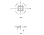
例えば、従来の医療用混注ポートにおける弁1の形状は、図2に示すようになる。図2は従来の医療用混注ポートにおける弁1の形状を示すものであり、図2(a)は平面図を、図2(b)はII―II断面における横断面図である。
For example, the shape of the
図2に示すように、弁1の中央部と周縁部においては、その肉厚が一致していることから、図3に示すように嵌合孔6を形成するカバー2の縁端部には必ず一定の段差部分10が生じることになる。したがって、残液や残血等のふき取り時には、かかる段差の存在によって当該段差部分10にふき残しが生じ、残液や残血等をきれいにふき取ることができないことになる。
As shown in FIG. 2, the thickness of the
かかる残液や残血等が生じることで、他の薬液との混入による人体への悪影響を回避するため、混注ポート自体の再利用性が著しく損なわれるとともに、特に残血による感染症対策上からも容易にふき取ることができることが強く要請されるものである。 The occurrence of such residual liquids and residual blood, etc., avoids adverse effects on the human body due to contamination with other chemicals, significantly reducing the reusability of the co-infusion port itself, and in particular, from the viewpoint of measures against infectious diseases caused by residual blood. It is strongly demanded that it can be easily wiped off.
本発明は、上記問題点を解消するべく、残液や残血等をきれいにふき取ることができる医療用混注ポートを提供することを目的とする。 SUMMARY OF THE INVENTION An object of the present invention is to provide a medical co-infusion port that can wipe off residual liquid, residual blood, etc., in order to solve the above problems.
本発明の医療用混注ポートは、中央部に挿入孔の形成されたディスク状の弁と、前記弁の裏側面の中央部を残して周縁下部を担持する台座と、前記弁の表側面の中央部を残して少なくとも前記弁の周縁上部を覆って前記弁を拘持するカバーとを備えた医療用混注ポートであって、前記弁の中央部における肉厚が前記弁の周縁部における肉厚よりも厚く、前記カバー中央において隆起した隆起部を備え、前記ディスク状の弁を貫通して挿入された挿入体をその後離脱させたときに、前記隆起部の弾性復元力によって、前記カバー中央部の開口部を閉鎖することを特徴とする。 The medical co-infusion port of the present invention includes a disc-shaped valve having an insertion hole formed in a central portion, a pedestal supporting a lower peripheral portion except for a central portion of a back side surface of the valve, and a center of a front side surface of the valve. A medical co-infusion port comprising: a cover for covering at least an upper portion of the periphery of the valve while retaining the portion, and covering the valve, wherein the thickness at the center of the valve is greater than the thickness at the periphery of the valve. The cover is provided with a raised portion at the center of the cover, and when the inserted body inserted through the disc-shaped valve is subsequently removed, the elastic restoring force of the raised portion causes the cover to have a raised portion. The opening is closed.
本発明の医療用混注ポートによれば、弁の上面を残液や残血等が生じることなくきれいにふき取ることができるので、患者に対する輸血や輸液を行うに当たって、万一、不注意や誤操作等によって薬液や血液等が弁の上面に漏れ出したとしても、容易にふき取ることができ、衛生的にかつ安全に医療活動を行うことが可能となる。 According to the medical co-infusion port of the present invention, the upper surface of the valve can be wiped clean without generating residual liquid, residual blood, etc., so that when performing blood transfusion or transfusion to a patient, careless or erroneous operation may occur. Even if a drug solution, blood, or the like leaks to the upper surface of the valve, it can be easily wiped off, and medical activities can be performed hygienically and safely.
本発明の医療用混注ポートにおいて、好ましくは、前記ディスク状の弁を貫通して挿入された挿入体を係止する係止手段を更に備える。 In the medical co-infusion port of the present invention, preferably, the medical co-infusion port further includes locking means for locking the inserted body inserted through the disc-shaped valve.
以下、本発明の実施の形態にかかる医療用混注ポートについて、図面を参照しながら説明する。図4は、本発明の実施の形態にかかる医療用混注ポートにおける弁1の断面図を示す。図4において、ディスク状の弁である点においては図2と共通しているが、弁1の中央部における肉厚が周縁部における肉厚よりも厚い点において相違している。なお、中央部と周縁部とは、弁切り欠き部4を境界とするものとする。
Hereinafter, a medical co-infusion port according to an embodiment of the present invention will be described with reference to the drawings. FIG. 4 is a sectional view of the
図5は、本発明の実施の形態にかかる医療用混注ポートにおける弁1を混注ポートにカバー2によって装着したときの断面図である。図5に示すように、弁1の中央部における肉厚が厚いために、カバー2の嵌合孔6を覆うように弁1が装着される。すなわち、嵌合孔6を形成するカバー2の縁端部における肉厚と、弁1の中央部における肉厚と周縁部における肉厚との差を一致させることによって、カバー2と弁1の間に段差が生じないようにすることができる。
FIG. 5 is a cross-sectional view when the
かかる構造にすることにより、カバー2と弁1との間に生じていた段差を解消することができることから、万一、薬液や血液が弁1の上面に漏れ出したとしても、それらを容易にふき取ることができ、段差によって生じる残液や残血等が生じることを未然に回避することが可能となる。
By adopting such a structure, a step generated between the
そして、残液や残血等が生じることなくきれいにふき取ることができることによって、患者に対する輸血や輸液を行うに当たって、万一、不注意や誤操作等によって薬液や血液が弁の上面に漏れだしたとしても、それらを容易にふき取ることができ、衛生的にかつ安全に医療活動を行うことが可能となる。 And because it can be wiped clean without generating residual liquid or residual blood, even if medical fluid or blood leaks to the upper surface of the valve due to carelessness or incorrect operation when performing blood transfusion or transfusion to the patient These can be easily wiped off, and medical activities can be performed hygienically and safely.
また、弁1の中央部における肉厚が周縁部における肉厚よりも相対的に厚くなっていることから、挿入体を差し込む際に弁1を押し下げる時の弁1の弾性による反力が強く、挿入体を奥まで差し込むことが困難になり、あるいは挿入体を保持することが困難になることも考えられる。
In addition, since the thickness at the center of the
実験的には、図5に示すように、カバー2の縁端部における肉厚D1に対して、弁1の中央部における肉厚と弁1の周縁部における肉厚の差D2が60%以上80%以下である場合には、上記弊害が生じないことが確認されている。なお、本実験結果は、弁1の材質として合成イソブレンゴムを用いた場合の結果であるが、材質としては特にこれに限定されるものではなく、例えばシリコーンゴムや天然ゴム、ブチルゴム、ニトリルゴム等の合成ゴムに代表される硬度JIS−A:20〜55の範囲内である熱可塑性エラストマーを用いた場合であっても同様の効果が期待できる。
Experimentally, as shown in FIG. 5, the difference D2 between the thickness at the center of the
本発明の医療用混注ポートによれば、輸血や輸液を行うに当たって、万一、不注意や誤操作等によって薬液や血液等が弁の上面に漏れ出したとしても、容易にふき取ることができ、衛生的にかつ安全に医療活動を行うことが可能となる。 ADVANTAGE OF THE INVENTION According to the medical co-infusion port of this invention, when performing a blood transfusion or infusion, even if a medical solution, blood, etc. leaked to the upper surface of a valve by carelessness or erroneous operation, it can be wiped off easily, Medical activities can be performed efficiently and safely.
1 弁(ディスク弁)
2 カバー
3 挿入孔(スリット)
4 弁切欠き部
5 環状リブ
6 嵌合孔
7 台座
8 流路(開口部)
9 鉤部
10 段差部分
11 凹部
1 valve (disk valve)
2
4
9
Claims (2)
前記弁の中央部における肉厚が前記弁の周縁部における肉厚よりも厚く、前記カバー中央において隆起した隆起部を備え、
前記ディスク状の弁を貫通して挿入された挿入体をその後離脱させたときに、前記隆起部の弾性復元力によって、前記カバー中央部の開口部を閉鎖することを特徴とする医療用混注ポート。 A disk-shaped valve having an insertion hole formed in a central portion thereof, a pedestal for supporting a lower peripheral portion of the valve except for a central portion of a back surface of the valve, and at least a peripheral portion of the valve except for a central portion of a front surface of the valve. A medical co-infusion port comprising: a cover that covers an upper portion and holds the valve.
A thickness at a central portion of the valve is thicker than a thickness at a peripheral portion of the valve, and includes a raised portion raised at the center of the cover,
A medical co-infusion port, wherein when the inserted body inserted through the disc-shaped valve is subsequently removed, the opening of the central portion of the cover is closed by the elastic restoring force of the raised portion. .
2. The medical co-infusion port according to claim 1, further comprising a locking means for locking an insert inserted through the disc-shaped valve.
Priority Applications (1)
| Application Number | Priority Date | Filing Date | Title |
|---|---|---|---|
| JP2004157688A JP2004237134A (en) | 2004-05-27 | 2004-05-27 | Mixed injection port for medical treatment |
Applications Claiming Priority (1)
| Application Number | Priority Date | Filing Date | Title |
|---|---|---|---|
| JP2004157688A JP2004237134A (en) | 2004-05-27 | 2004-05-27 | Mixed injection port for medical treatment |
Related Parent Applications (1)
| Application Number | Title | Priority Date | Filing Date |
|---|---|---|---|
| JP2000292024A Division JP4016313B2 (en) | 2000-09-26 | 2000-09-26 | Medical mixed injection port |
Publications (1)
| Publication Number | Publication Date |
|---|---|
| JP2004237134A true JP2004237134A (en) | 2004-08-26 |
Family
ID=32960094
Family Applications (1)
| Application Number | Title | Priority Date | Filing Date |
|---|---|---|---|
| JP2004157688A Pending JP2004237134A (en) | 2004-05-27 | 2004-05-27 | Mixed injection port for medical treatment |
Country Status (1)
| Country | Link |
|---|---|
| JP (1) | JP2004237134A (en) |
Citations (6)
| Publication number | Priority date | Publication date | Assignee | Title |
|---|---|---|---|---|
| JPH0238023A (en) * | 1988-07-28 | 1990-02-07 | Sekisui Chem Co Ltd | Connecting structure of cylindrical body and connecting member, and container employing said connecting structure for medical treatment |
| JPH0383551U (en) * | 1989-12-19 | 1991-08-26 | ||
| JPH0722739U (en) * | 1993-10-06 | 1995-04-25 | 株式会社新素材総合研究所 | Container port seal structure |
| JPH11197254A (en) * | 1997-10-23 | 1999-07-27 | Jms Co Ltd | Medical mixing and filling port |
| JP2000102593A (en) * | 1998-09-29 | 2000-04-11 | Kawasumi Lab Inc | Mixing injection member, medical instrument, opening part and medical container |
| JP2002095759A (en) * | 2000-09-26 | 2002-04-02 | Jms Co Ltd | Medical mixed injection port |
-
2004
- 2004-05-27 JP JP2004157688A patent/JP2004237134A/en active Pending
Patent Citations (6)
| Publication number | Priority date | Publication date | Assignee | Title |
|---|---|---|---|---|
| JPH0238023A (en) * | 1988-07-28 | 1990-02-07 | Sekisui Chem Co Ltd | Connecting structure of cylindrical body and connecting member, and container employing said connecting structure for medical treatment |
| JPH0383551U (en) * | 1989-12-19 | 1991-08-26 | ||
| JPH0722739U (en) * | 1993-10-06 | 1995-04-25 | 株式会社新素材総合研究所 | Container port seal structure |
| JPH11197254A (en) * | 1997-10-23 | 1999-07-27 | Jms Co Ltd | Medical mixing and filling port |
| JP2000102593A (en) * | 1998-09-29 | 2000-04-11 | Kawasumi Lab Inc | Mixing injection member, medical instrument, opening part and medical container |
| JP2002095759A (en) * | 2000-09-26 | 2002-04-02 | Jms Co Ltd | Medical mixed injection port |
Similar Documents
| Publication | Publication Date | Title |
|---|---|---|
| JP3389983B2 (en) | Medical injection port | |
| JP4775638B2 (en) | Communication member, medical container using the same, and infusion dispensing device set | |
| US6827709B2 (en) | Mixing/charging port for medical treatment | |
| JP4016313B2 (en) | Medical mixed injection port | |
| JP3404738B2 (en) | Medical injection port | |
| JP2010075684A (en) | Medical port | |
| JP2010167202A (en) | Medical port | |
| JP2004237133A (en) | Mixed injection port for medical treatment | |
| JP2004237134A (en) | Mixed injection port for medical treatment | |
| JP6715384B2 (en) | Safe drug delivery system | |
| JP2003339876A (en) | Mixing injector | |
| JP2006212084A (en) | Connector | |
| JP4572804B2 (en) | Liquid transfer tool | |
| JP2007268311A (en) | Medical mixed injection port | |
| JP2017153729A (en) | Filter assembly and filter | |
| JP3747912B2 (en) | Medical mixed injection port | |
| JP2004237130A (en) | Mixed injection port for medical treatment | |
| JP2004237132A (en) | Mixed injection port for medical treatment | |
| US8608711B2 (en) | Infusion port | |
| JP3646727B2 (en) | Medical mixed injection port | |
| US20060089606A1 (en) | Medicine-adding port of vein infusion set and catheter needle set | |
| JP2004033360A (en) | Syringe connection port for infusion | |
| JP2010051701A (en) | Subcutaneous infusion device | |
| JP2004321690A (en) | Medical dosage instrument | |
| JP2000014797A (en) | Mixed injection port |
Legal Events
| Date | Code | Title | Description |
|---|---|---|---|
| A621 | Written request for application examination |
Free format text: JAPANESE INTERMEDIATE CODE: A621 Effective date: 20040527 |
|
| A131 | Notification of reasons for refusal |
Free format text: JAPANESE INTERMEDIATE CODE: A131 Effective date: 20060720 |
|
| A02 | Decision of refusal |
Free format text: JAPANESE INTERMEDIATE CODE: A02 Effective date: 20061114 |