EP1396250B1 - Transfer needle assembly - Google Patents
Transfer needle assembly Download PDFInfo
- Publication number
- EP1396250B1 EP1396250B1 EP20030019584 EP03019584A EP1396250B1 EP 1396250 B1 EP1396250 B1 EP 1396250B1 EP 20030019584 EP20030019584 EP 20030019584 EP 03019584 A EP03019584 A EP 03019584A EP 1396250 B1 EP1396250 B1 EP 1396250B1
- Authority
- EP
- European Patent Office
- Prior art keywords
- puncture
- needle
- tip
- puncture needle
- guide member
- Prior art date
- Legal status (The legal status is an assumption and is not a legal conclusion. Google has not performed a legal analysis and makes no representation as to the accuracy of the status listed.)
- Expired - Lifetime
Links
Images


Classifications
-
- A—HUMAN NECESSITIES
- A61—MEDICAL OR VETERINARY SCIENCE; HYGIENE
- A61J—CONTAINERS SPECIALLY ADAPTED FOR MEDICAL OR PHARMACEUTICAL PURPOSES; DEVICES OR METHODS SPECIALLY ADAPTED FOR BRINGING PHARMACEUTICAL PRODUCTS INTO PARTICULAR PHYSICAL OR ADMINISTERING FORMS; DEVICES FOR ADMINISTERING FOOD OR MEDICINES ORALLY; BABY COMFORTERS; DEVICES FOR RECEIVING SPITTLE
- A61J1/00—Containers specially adapted for medical or pharmaceutical purposes
- A61J1/14—Details; Accessories therefor
- A61J1/20—Arrangements for transferring or mixing fluids, e.g. from vial to syringe
- A61J1/2096—Combination of a vial and a syringe for transferring or mixing their contents
-
- A—HUMAN NECESSITIES
- A61—MEDICAL OR VETERINARY SCIENCE; HYGIENE
- A61J—CONTAINERS SPECIALLY ADAPTED FOR MEDICAL OR PHARMACEUTICAL PURPOSES; DEVICES OR METHODS SPECIALLY ADAPTED FOR BRINGING PHARMACEUTICAL PRODUCTS INTO PARTICULAR PHYSICAL OR ADMINISTERING FORMS; DEVICES FOR ADMINISTERING FOOD OR MEDICINES ORALLY; BABY COMFORTERS; DEVICES FOR RECEIVING SPITTLE
- A61J1/00—Containers specially adapted for medical or pharmaceutical purposes
- A61J1/14—Details; Accessories therefor
- A61J1/20—Arrangements for transferring or mixing fluids, e.g. from vial to syringe
- A61J1/2003—Accessories used in combination with means for transfer or mixing of fluids, e.g. for activating fluid flow, separating fluids, filtering fluid or venting
- A61J1/2006—Piercing means
- A61J1/201—Piercing means having one piercing end
-
- A—HUMAN NECESSITIES
- A61—MEDICAL OR VETERINARY SCIENCE; HYGIENE
- A61J—CONTAINERS SPECIALLY ADAPTED FOR MEDICAL OR PHARMACEUTICAL PURPOSES; DEVICES OR METHODS SPECIALLY ADAPTED FOR BRINGING PHARMACEUTICAL PRODUCTS INTO PARTICULAR PHYSICAL OR ADMINISTERING FORMS; DEVICES FOR ADMINISTERING FOOD OR MEDICINES ORALLY; BABY COMFORTERS; DEVICES FOR RECEIVING SPITTLE
- A61J1/00—Containers specially adapted for medical or pharmaceutical purposes
- A61J1/14—Details; Accessories therefor
- A61J1/20—Arrangements for transferring or mixing fluids, e.g. from vial to syringe
- A61J1/2003—Accessories used in combination with means for transfer or mixing of fluids, e.g. for activating fluid flow, separating fluids, filtering fluid or venting
- A61J1/2068—Venting means
- A61J1/2075—Venting means for external venting
-
- A—HUMAN NECESSITIES
- A61—MEDICAL OR VETERINARY SCIENCE; HYGIENE
- A61J—CONTAINERS SPECIALLY ADAPTED FOR MEDICAL OR PHARMACEUTICAL PURPOSES; DEVICES OR METHODS SPECIALLY ADAPTED FOR BRINGING PHARMACEUTICAL PRODUCTS INTO PARTICULAR PHYSICAL OR ADMINISTERING FORMS; DEVICES FOR ADMINISTERING FOOD OR MEDICINES ORALLY; BABY COMFORTERS; DEVICES FOR RECEIVING SPITTLE
- A61J1/00—Containers specially adapted for medical or pharmaceutical purposes
- A61J1/14—Details; Accessories therefor
- A61J1/20—Arrangements for transferring or mixing fluids, e.g. from vial to syringe
- A61J1/2003—Accessories used in combination with means for transfer or mixing of fluids, e.g. for activating fluid flow, separating fluids, filtering fluid or venting
- A61J1/2079—Filtering means
- A61J1/2082—Filtering means for gas filtration
Landscapes
- Health & Medical Sciences (AREA)
- Pharmacology & Pharmacy (AREA)
- Life Sciences & Earth Sciences (AREA)
- Animal Behavior & Ethology (AREA)
- General Health & Medical Sciences (AREA)
- Public Health (AREA)
- Veterinary Medicine (AREA)
- Infusion, Injection, And Reservoir Apparatuses (AREA)
- Medical Preparation Storing Or Oral Administration Devices (AREA)
Description
- The present invention relates to a transfer needle assembly for transferring fluid from a fluid source to a vial containing a solid material or a liquid material. The transfer needle assembly of the present invention eliminates problems such as contamination of a tip of a puncture needle in the transfer needle assembly before use and injury to an operator's finger by the tip of the puncture needle and fluid leakage from the transfer needle assembly when in use.
- In order to prepare a liquid medical component for adhering tissues in a living body or to be mixed with a solid component at a medical facility, or to be injected by a patient himself for home medical treatment, a dried or liquid medicine contained in a vial is dissolved with a fluid such as saline to make a medicinal solution which is then transferred to a syringe. A syringe with a puncture needle or a tool having two hollow puncture needles at both ends, called a "double-ended needle", has been used for these operations. When the syringe with a needle is used, a rubber stopper in a mouth portion of a fluid container is pricked with the puncture needle to collect a predetermined amount of the fluid into the syringe and then, a rubber stopper in a mouth portion of a vial is pricked with the same needle to inject the fluid into the vial from the syringe. Then,thevialisshakentodissolvethemedicinewith the fluid and the rubber stopper is pricked with the above needle again to collect a predetermined amount of the medicinal solution into the syringe. When the "double-ended needle" is used, the rubber stopper of the vial filled with a dried medicine is pricked with one puncture neddle of the double-ended needle and the rubber stopper of the fluid container is pricked with another puncture needle, respectively, which are located at both ends of the double-ended needle to communicate the vial with the fluid container. The fluid in the fluid container is transferred to the vial to dissolve the dried medicine, then, the fluid container and the double-ended needle are removed from the vial, and finally, the rubber stopper of the vial is pricked with a syringe with a needle likewise to collect a predetermined amount of the medicinal solution into the syringe.
- These prior techniques involve a problem in that when the procedure of dissolving a dried medicine is carried out using the syringe with a needle, the procedure is complicated, the tip of the puncture needle may be contaminated before use because the needle is exposed, and an operator may get injured by the tip of the needle when in use. When the double-ended needle is used and the needle is pulled out or a predetermined amount of the medicinal solution is collected into the syringe, the operator may get injured by the tips of the needle, and the tips of the needle may be contaminated before the collection of the medicinal solution because the tips of the needle are exposed like the syringe with a needle. To solve the above problems, there is proposed an admixture injection adaptor which enables both injection and collection of a medicinal solution during a dissolution procedure (refer to
JP 7-213585 A Fig. 1 andFig. 2 ) - In the admixture injection adaptor in this reference, a hollow puncture needle and a tubular tip fitting part, respectively, are set on opposite sides on the axis of a discoid hub, and a tubular vial fitting part which is concentrically extended over the tip of the puncture needle and a tubular syringe fitting part which is concentrically extended over the tip of the tip fitting part are constructed on the outer edge of the hub. The adaptor can conveniently transfer a medicinal solution in a vial to a syringe after medicine in the vial is dissolved with a fluid to prepare the medicinal solution while contamination of the tip of the needle or injury by the needle is avoided. However, the length of the skirt is limited so as to prevent the end of the skirt from contacting with the shoulder of the vial when the vial is pricked with the needle, whereby the vial cannot be fitted straight and, therefore, a gap is formed between the rubber stopper of the vial and the needle to cause leakage of the medicinal solution during dissolution.
- The
United States Patent No. 4,576,221 discloses a safety device for connection of a syringe with a mouth or opening of a bottle containing a drug or a small tube for the drug delivery from the syringe. The device comprises a closed chamber having enclosed therein a needle which is in connection with the syringe. - The
United States Patent No. 6,070,623 discloses a device according to the preamble ofclaim 1. - The present invention has been made in view of the above circumstances, and it is, therefore, an object or the present invention to provide a transfer needle assembly having the following advantages: dried medicine can be easily dissolved; contamination of the tip of the needle and injury of an operator by the tip of the needle can be avoided; and leakage of a fluid from the transfer needle assembly during dissolution can be prevented.
- According to the present invention, this object is achieved by a transfer needle assembly as defined in
claim 1. The dependent claims define preferred and advantageous embodiments of the invention. - In order to solve the above problems, the inventor of the present invention has carried out extensive studies. The inventor understood that it would be desirable that the tip of the puncture member be capable of sliding from a position where the tip is receded in a skirt portion to a position where the tip projects from the skirt portion during transferring and injecting of a fluid, thereby reaching the present invention. Namely, the present invention relates to a transfer needle assembly comprising;
a cap-like guide member having a top surface, a skirt portion and a tubular puncture needle insertion portion penetrated through the top surface in the axial direction of the cap-like guide member; and
a puncture member comprising a tubular member provided with a tip fitting portion at the proximal end thereof for fitting a tip of a syringe and a puncture needle at the distal end thereof to be inserted into the puncture needle insertion portion of the cap-like guide member, and a filter portion;
wherein the puncture needle has a needle tip and is provided with a gas passage and a liquid passage; and the liquid passage communicates with the tip fitting portion and the gas passage is open to the outside through an air filter in the filter portion, and
wherein the puncture member is fitted in the puncture needle insertion portion of the cap-like guide member in such a manner that the needle tip of the puncture needle in the puncture member slides from a position where the needle tip is receded in the skirt portion to a position where the needle tip projects from the skirt portion. - Here, it is desirable that a cutout is formed in the skirt portion of the guide member so that the puncture needle which recedes into the skirt portion can be seen. A disk-like, preferably sector disk-like collar may also be provided at the proximal end of the puncture needle to stop sliding in a forward direction of the puncture member when the collar comes in contact with the proximal end of the puncture needle insertion portion. It is also desirable that the inner wall of the puncture needle insertion portion is undercut to form a stepped portion while retaining the proximal end portion thereof, an intermediate portion of the puncture needle is provided with an annular projection, and the stepped portion formed by undercutting engages with the annular projection to stop sliding of the puncture member in a backward direction.
- Slide suppression means for preventing accidental sliding of the puncture member may also be provided between the collar of the puncture member and the top surface of the guide member. The slide suppression means is suitably a spring or a prop.
-
-
Fig. 1 is a front view of an embodiment of the present invention. -
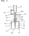
Fig. 2 is a sectional view cut on line X-X ofFig. 1 . -
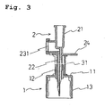
Fig. 3 is a longitudinal sectional view of another embodiment of the present invention. -
Fig. 4 is a front view of still another embodiment of the present invention. -
Fig. 5 is a front sectional view ofFig.4 . -
Fig. 6 is a sectional view cut on line Y-Y ofFig. 4 . -
Fig. 7 is a diagram for explaining use of the transfer needle assembly of the present invention. -
Fig. 8 is a diagram for explaining use of the transfer needle assembly of the present invention. - Preferred embodiments of the present invention will be described with reference to the accompanying drawings.
- As shown in
Figs. 1 to 6 , the transfer needle assembly of the present invention includes a cap-like guide member 1 having atop surface 11, askirt portion 13 and a punctureneedle insertion portion 12; and apuncture member 2 fitted in the punctureneedle insertion portion 12 of the cap-like guide member 1 in such a manner that aneedle tip 223 of apuncture needle 22 in thepuncture member 2 slides from a position where theneedle tip 223 is receded into theskirt portion 13 to a position where theneedle tip 223 projects from theskirt portion 13. - The
guide member 1 is generally a cap-like member formed from a plastic such as polypropylene, polyethylene, polyester, polyvinyl chloride, polycarbonate or ABS resin and has thetop surface 11, theskirt portion 13 and thetubular insertion portion 12 forpuncture needle 22 penetrated through thetop surface 11 in the axial direction of the transfer needle assembly. Theskirt portion 13 has an inner diameter that enables a mouth portion of a vial (not shown) to slide along the inner wall thereof and acutout 14, formed on the distal end side thereof, for identifying thepuncture needle 22 situated at a position where the needle is receded into theskirt portion 13. A plurality of (generally 3 to 5)vertical ribs 15 which enable the mouth portion of the vial to slide smoothly are provided on the inner wall of theskirt portion 13. Thevertical ribs 15 are undercut with their proximal end portions retained adjacent to thetop surface 11, and steppedportions 151 formed by the undercutting come in contact with the mouth portion of the vial when theend 131 of theskirt portion 13 advances to a position where theend 131 contacts the shoulder portion of the vial. - The inner wall of the puncture
needle insertion portion 12 is undercut with part of its proximal end retained and thepuncture needle 22 of thepuncture member 2 is inserted into this portion in such a manner that thepuncture needle 22 can slide along the inner wall. Owing to this structure, thepuncture member 2 can recede up to a position where anannular rib 224 of thepuncture needle 22 to be described hereinafter is engaged with astepped portion 121 formed by the undercutting. Therefore, the undercutting position and the position of theannular rib 224 are determined such that thetip 223 of thepuncture member 2, that is, thetip 223 of thepuncture needle 22, is receded into theskirt portion 13 when theannular rib 224 and thestepped portion 121 engage with each other (see,Fig. 7 ). Thepuncture member 2 can advance up to a position where theproximal end 122 of the punctureneedle insertion portion 12 comes in contact with acollar 24 of thepuncture member 2 to be described hereinafter. Therefore, the projecting length of the punctureneedle insertion portion 12 from thetop surface 11 is determined such that thetip 223 of thepuncture member 2 projects from theskirt portion 13 when theproximal end 122 of the punctureneedle insertion portion 12 comes in contact with thecollar 24 of the puncture member 2 (see,Fig. 8 ). - The
puncture member 2 is generally a tubular member formed from a plastic such as polypropylene, polyethylene, polyester, polycarbonate or ABS resin and atip 223 of thepuncture needle 22 is fitted in the punctureneedle insertion portion 12 of theguide member 1 in such a manner that thetip 223 can slide from a position where thetip 223 is receded in the inside of theskirt portion 13 to a position where thetip 223 projects from theskirt portion 13. Thepuncture member 2 has, at the proximal end thereof, thetip fitting portion 21 into which a tip (not shown) of a syringe can be mounted and, at the distal end thereof, thepuncture needle 22 to be inserted into the punctureneedle insertion portion 12. - In detail, the
puncture member 2 is a tubular member having, at its proximal end, atip fitting portion 21 and apuncture needle 22, at its distal end, to be inserted into the above punctureneedle insertion portion 12 and which also has afilter portion 23. Thetip fitting portion 21 comprises a cylindrical area for accommodating a syringe and for mounting a tip of the syringe and an aperture on the bottom. The aperture is preferably, crescent, semicircular, elliptical or circular, but is not limited to these shapes. Thepuncture needle 22 includes a tubular outer wall of which a proximal end is partly connected with the bottom of thetip fitting portion 21, but the remaining proximal part is connected with thefilter portion 23, and a needle shaped septum continued from the aperture of thetip fitting portion 21. The outer wall and the septum form a liquid passage from thetip fitting portion 21 to theguide member 1 and a gas passage from thefilter portion 23 to theguide member 1. The cross-sectional area of the liquid passage is preferably, crescent, semicircular, elliptical or circular, and the cross-sectional area of the gas passage is, preferably, circular. - The length of the septum is longer than the length of the outer wall of the puncture needle, and the distal end of the outer wall of the gas passage extends downwardly beyond the distal end of the outer wall of the liquid passage in order to prevent the air introduced into the vial from returning to the syringe.
- The
filter portion 23 is located outside of thetip fitting portion 12 and connected with the outer wall of thepuncture needle 22 and is provided with anair filter 231 at the proximal end of the gas passage. Thefilter portion 23 preferably, locates in a position where a lock-typed syringe is not contact thetip fitting portion 21 and further, a position where the movements of the disk-like collar 24 and the puncture needlefitting portion 12 are not disturbed when thecollar 24 comes in contact with the puncture needlefitting portion 12. Thefilter portion 23 is, preferably, a cylindrical portion extending from the outside of thetip fitting portion 21 and the outer wall of thepuncture needle 22, but is not limited to this shape. - That is, the
puncture needle 22 is provided with aliquid passage 222 which communicates with thetip fitting portion 21 and agas passage 221 which communicates with the outside through anair filter 231 in thefilter portion 23. - The
gas passage 221 enables outside air to be introduced into the mouth portion of the vial via theair filter 231 in thefilter portion 23 and theliquid passage 222 enables a fluid to be injected into the mouth of the vial through thetip 223. Theliquid passage 222 communicates with thetip fitting portion 21, and thegas passage 221 is open to the outside through theair filter 231 of thefilter portion 23 which communicates with thegas passage 221. - The vial filled with a medicine such as a biological agent usually has a reduced pressure on the inside while freeze-drying the medicine. When a syringe filled with a dissolution fluid such as saline is connected with the vial by means of the transfer needle assembly, outside air is introduced into the vial in order to release the reduced pressure. The
filter portion 23 is provided in thegas passage 221 to prevent the air contamination via theair filter 231. In case of a syringe filled with a dissolution fluid and connected with thetip fitting portion 21, air is also introduced into the vial when the dissolution fluid is introduced into the vial containing a dried medicine and mixed to prepare the medicinal solution, and the solution is returned back into the syringe again. - In the present invention, for example, a disk-like, preferably, sector disk-like,
collar 24 may be provided at the proximal end of thepuncture needle 22 so that thecollar 24 comes in contact with theproximal end 122 of the punctureneedle insertion portion 12 at a position where thetip 223 of thepuncture member 2 projects from theskirt portion 13 to stop the sliding of thepuncture member 2 in a forward direction of thepuncture member 2. - The intermediate portion of the
puncture needle 22 is provided with theannular rib 224 which is engaged with the steppedportion 121 of the punctureneedle insertion portion 12 at a position where thetip 223 of thepuncture member 2 is receded into theskirt portion 13 to stop the sliding of thepuncture member 2 in a backward direction of thepuncture member 2. - To prevent the
puncture member 2 from sliding accidentally, slide suppressing means may be provided between thecollar 24 of thepuncture member 2 and thetop surface 11 of theguide member 1. The slide suppressing means is suitably aspring 32 as shown inFigs. 4 to 6 or aprop 31 having a corset function as shown inFig. 3 . - A description is given below of use of the transfer needle assembly of the present invention with reference to
Fig. 7 andFig. 8 - As shown in
Fig. 7 , a transfer needle assembly TN and a vial V are first prepared. Thetip 223 of thepuncture needle 22 is situated within theskirt portion 13. Theskirt portion 13 is applied to the mouth portion M of the vial V, the whole transfer needle assembly TN is pressed down straight, a rubber stopper RS is pricked with thepuncture needle 22, and the forward movement of the transfer needle assembly TN is stopped at a position where the punctureneedle insertion portion 12 comes in contact with the sector disk-like collar 24. At this point, the steppedportion 151 engages the mouth portion M of the vial V, and the inside of the vial V communicates with the outside air and thetip fitting portion 21 through thegas passage 221 and theliquid passage 222 of thepuncture needle 22, respectively (seeFig. 8 ). When thetip fitting portion 21 is connected to a syringe (not shown) filled with the fluid in this state, the dissolution procedure can be easily carried out by introducing the fluid in the syringe into the mouth portion M of the vial V. - As obvious from the above description, by using the present invention, the dissolution procedure can be easily carried out. Contamination of the tip of the needle and injury by the tip of the needle can be avoided and leakage of a liquid during the dissolution procedure can be prevented.
Claims (7)
- A transfer needle assembly comprising
a cap-like guide member (1) having a skirt portion (13)
a puncture member (2) comprising a tubular member provided with a tip fitting portion (21) at a proximal end thereof for fitting a tip of a syringe and a puncture needle (22) at the distal end thereof and a filter portion (23);
wherein the puncture needle (22) has a needle tip (223) and is provided with a gas passage (221) and a liquid passage (222); and the liquid passage (222) communicates with the tip fitting portion (21) and the gas passage (221) is open to the outside through an air filter (231) in the filter portion (23), characterized in that the cap-like guide member (1) further comprises a top surface (11) and a tubular puncture needle insertion portion (12) penetrated through the top surface (11) in an axial direction of the cap-like guide member (1)
wherein the puncture needle (22) is to be inserted into the puncture needle insertion portion (12) of the cap-like guide member (1), and that
the puncture member (2) is fitted in the puncture needle insertion portion (12) of the cap-like guide member (1) in such a manner that the needle tip (223) of the puncture needle (22) in the puncture member (2) can slide from a position where the needle tip (223) is receded into the skirt portion (13) to a position where the needle tip (223) projects from the skirt portion (13). - The transfer needle assembly according to claim 1, wherein a cutout (14) is formed in the skirt portion (13) of the cap-like guide member (1) so that the needle tip (223) of the puncture needle (22) which is receded into the skirt portion (13) can be seen.
- The transfer needle assembly according to claim 1 or claim 2, wherein a disk-like collar (24) is provided at the proximal end of the puncture needle (22) to stop sliding of the puncture member (2) in a forward direction of the puncture member (2) when the collar (24) comes in contact with the proximal end (122) of the puncture needle insertion portion (12).
- The transfer needle assembly according to any one of claims 1-3, wherein an inner wall of the puncture needle insertion portion (12) is undercut to form a stepped portion (121) at a proximal end thereof, an intermediate portion of the puncture needle (22) is provided with an annular projection (224), and the stepped portion (121) formed by undercutting is engageable with the annular projection (224) to stop sliding of the puncture member (2) in a backward direction of the puncture member (2).
- The transfer needle assembly according to any one of claims 1-4, wherein a slide suppression means (32) for preventing accidental sliding of the puncture member (2) is provided between a collar (24) of the puncture member (2) and the top surface (11) of the guide member (1).
- The transfer needle assembly according to claim 5, wherein the slide suppression means (32) is a spring.
- The transfer needle assembly according to claim 5, wherein the slide suppression means (32) is a prop.
Applications Claiming Priority (2)
| Application Number | Priority Date | Filing Date | Title |
|---|---|---|---|
| JP2002259227 | 2002-09-04 | ||
| JP2002259227A JP2004097253A (en) | 2002-09-04 | 2002-09-04 | Liquid transfusion device |
Publications (2)
| Publication Number | Publication Date |
|---|---|
| EP1396250A1 EP1396250A1 (en) | 2004-03-10 |
| EP1396250B1 true EP1396250B1 (en) | 2011-01-26 |
Family
ID=31712312
Family Applications (1)
| Application Number | Title | Priority Date | Filing Date |
|---|---|---|---|
| EP20030019584 Expired - Lifetime EP1396250B1 (en) | 2002-09-04 | 2003-09-03 | Transfer needle assembly |
Country Status (5)
| Country | Link |
|---|---|
| US (1) | US20040044327A1 (en) |
| EP (1) | EP1396250B1 (en) |
| JP (1) | JP2004097253A (en) |
| CA (1) | CA2438760A1 (en) |
| DE (1) | DE60335846D1 (en) |
Families Citing this family (66)
| Publication number | Priority date | Publication date | Assignee | Title |
|---|---|---|---|---|
| IL114960A0 (en) | 1995-03-20 | 1995-12-08 | Medimop Medical Projects Ltd | Flow control device |
| US6989891B2 (en) | 2001-11-08 | 2006-01-24 | Optiscan Biomedical Corporation | Device and method for in vitro determination of analyte concentrations within body fluids |
| IL161660A0 (en) | 2004-04-29 | 2004-09-27 | Medimop Medical Projects Ltd | Liquid drug delivery device |
| DK1919432T3 (en) * | 2005-08-11 | 2012-01-30 | Medimop Medical Projects Ltd | Liquid Medication Transfer Devices for Safe Safe Resting Connection on Medical Vials |
| US7896859B2 (en) * | 2005-10-20 | 2011-03-01 | Tyco Healthcare Group Lp | Enteral feeding set |
| EP2540276B1 (en) | 2006-05-25 | 2016-03-16 | Bayer Healthcare LLC | Method of assembling a reconstitution device |
| US8002756B2 (en) * | 2006-12-08 | 2011-08-23 | Becton, Dickinson And Company | Method and apparatus for delivering a therapeutic substance through an injection port |
| IL182605A0 (en) | 2007-04-17 | 2007-07-24 | Medimop Medical Projects Ltd | Fluid control device with manually depressed actuator |
| WO2008144575A2 (en) | 2007-05-18 | 2008-11-27 | Optiscan Biomedical Corporation | Fluid injection and safety system |
| CA2704933A1 (en) | 2007-08-21 | 2009-02-26 | Yukon Medical, Llc | Vial access and injection system |
| EP2190518B1 (en) | 2007-09-18 | 2016-01-27 | Medimop Medical Projects Ltd. | Medicament mixing and injection apparatus |
| IL186290A0 (en) | 2007-09-25 | 2008-01-20 | Medimop Medical Projects Ltd | Liquid drug delivery devices for use with syringe having widened distal tip |
| DE102007061346A1 (en) * | 2007-12-17 | 2009-06-18 | Bayer Schering Pharma Aktiengesellschaft | Spike with two thorns |
| US8141601B2 (en) | 2008-10-02 | 2012-03-27 | Roche Diagnostics Operations, Inc. | Manual filling aid with push button fill |
| WO2010058806A1 (en) | 2008-11-21 | 2010-05-27 | テルモ株式会社 | Connector |
| JP5495006B2 (en) * | 2008-11-25 | 2014-05-21 | 株式会社ジェイ・エム・エス | connector |
| USD641080S1 (en) | 2009-03-31 | 2011-07-05 | Medimop Medical Projects Ltd. | Medical device having syringe port with locking mechanism |
| USD616984S1 (en) | 2009-07-02 | 2010-06-01 | Medimop Medical Projects Ltd. | Vial adapter having side windows |
| USD630732S1 (en) | 2009-09-29 | 2011-01-11 | Medimop Medical Projects Ltd. | Vial adapter with female connector |
| IL201323A0 (en) * | 2009-10-01 | 2010-05-31 | Medimop Medical Projects Ltd | Fluid transfer device for assembling a vial with pre-attached female connector |
| IL202069A0 (en) | 2009-11-12 | 2010-06-16 | Medimop Medical Projects Ltd | Fluid transfer device with sealing arrangement |
| IL202070A0 (en) | 2009-11-12 | 2010-06-16 | Medimop Medical Projects Ltd | Inline liquid drug medical device |
| JP5709905B2 (en) | 2010-02-24 | 2015-04-30 | メディモップ・メディカル・プロジェクツ・リミテッド | Liquid transfer device including vial adapter with vent |
| EP2512399B1 (en) | 2010-02-24 | 2015-04-08 | Medimop Medical Projects Ltd. | Fluid transfer assembly with venting arrangement |
| USD669980S1 (en) | 2010-10-15 | 2012-10-30 | Medimop Medical Projects Ltd. | Vented vial adapter |
| IL209290A0 (en) | 2010-11-14 | 2011-01-31 | Medimop Medical Projects Ltd | Inline liquid drug medical device having rotary flow control member |
| IL212420A0 (en) | 2011-04-17 | 2011-06-30 | Medimop Medical Projects Ltd | Liquid drug transfer assembly |
| IL215699A0 (en) | 2011-10-11 | 2011-12-29 | Medimop Medical Projects Ltd | Liquid drug reconstitution assemblage for use with iv bag and drug vial |
| USD674088S1 (en) | 2012-02-13 | 2013-01-08 | Medimop Medical Projects Ltd. | Vial adapter |
| USD720451S1 (en) | 2012-02-13 | 2014-12-30 | Medimop Medical Projects Ltd. | Liquid drug transfer assembly |
| USD737436S1 (en) | 2012-02-13 | 2015-08-25 | Medimop Medical Projects Ltd. | Liquid drug reconstitution assembly |
| IL219065A0 (en) | 2012-04-05 | 2012-07-31 | Medimop Medical Projects Ltd | Fluid transfer device with manual operated cartridge release arrangement |
| US11014696B2 (en) * | 2017-07-12 | 2021-05-25 | Vanrx Pharmasystems Inc. | Purgeable pharmaceutical fill needle |
| USD769444S1 (en) * | 2012-06-28 | 2016-10-18 | Yukon Medical, Llc | Adapter device |
| IL221635A0 (en) | 2012-08-26 | 2012-12-31 | Medimop Medical Projects Ltd | Drug vial mixing and transfer device for use with iv bag and drug vial |
| IL221634A0 (en) | 2012-08-26 | 2012-12-31 | Medimop Medical Projects Ltd | Universal drug vial adapter |
| JP5868555B2 (en) | 2012-09-13 | 2016-02-24 | メディモップ・メディカル・プロジェクツ・リミテッド | Nested female vial adapter |
| USD734868S1 (en) | 2012-11-27 | 2015-07-21 | Medimop Medical Projects Ltd. | Drug vial adapter with downwardly depending stopper |
| US9101717B2 (en) * | 2013-03-12 | 2015-08-11 | Carefusion 303, Inc. | Non-vented vial access syringe |
| IL225734A0 (en) | 2013-04-14 | 2013-09-30 | Medimop Medical Projects Ltd | Ready-to-use drug vial assemblages including drug vial and drug vial closure having fluid transfer member, and drug vial closure therefor |
| DK2983745T3 (en) | 2013-05-10 | 2018-10-22 | West Pharma Services Il Ltd | Medical devices comprising ampoule adapter with interconnected module for dry drug |
| USD767124S1 (en) | 2013-08-07 | 2016-09-20 | Medimop Medical Projects Ltd. | Liquid transfer device with integral vial adapter |
| JP3205560U (en) | 2013-08-07 | 2016-08-04 | メディモップ・メディカル・プロジェクツ・リミテッド | Liquid transfer device for use with a drip liquid container |
| USD765837S1 (en) | 2013-08-07 | 2016-09-06 | Medimop Medical Projects Ltd. | Liquid transfer device with integral vial adapter |
| USD757933S1 (en) | 2014-09-11 | 2016-05-31 | Medimop Medical Projects Ltd. | Dual vial adapter assemblage |
| CN108601706B (en) | 2015-01-05 | 2019-06-25 | 麦迪麦珀医疗工程有限公司 | With for guaranteeing the vial adapter component of proper use of quick release vial adapter |
| EP3319576B1 (en) | 2015-07-16 | 2019-10-02 | West Pharma. Services IL, Ltd | Liquid drug transfer devices for secure telescopic snap fit on injection vials |
| USD801522S1 (en) | 2015-11-09 | 2017-10-31 | Medimop Medical Projects Ltd. | Fluid transfer assembly |
| EP3380058B1 (en) | 2015-11-25 | 2020-01-08 | West Pharma Services IL, Ltd. | Dual vial adapter assemblage including drug vial adapter with self-sealing access valve |
| IL245803A0 (en) | 2016-05-24 | 2016-08-31 | West Pharma Services Il Ltd | Dual vial adapter assemblages including vented drug vial adapter and vented liquid vial adapter |
| IL245800A0 (en) | 2016-05-24 | 2016-08-31 | West Pharma Services Il Ltd | Dual vial adapter assemblages including identical twin vial adapters |
| IL246073A0 (en) | 2016-06-06 | 2016-08-31 | West Pharma Services Il Ltd | Fluid transfer devices for use with drug pump cartridge having slidable driving plunger |
| IL247376A0 (en) | 2016-08-21 | 2016-12-29 | Medimop Medical Projects Ltd | Syringe assembly |
| USD832430S1 (en) | 2016-11-15 | 2018-10-30 | West Pharma. Services IL, Ltd. | Dual vial adapter assemblage |
| IL249408A0 (en) | 2016-12-06 | 2017-03-30 | Medimop Medical Projects Ltd | Liquid transfer device for use with infusion liquid container and pincers-like hand tool for use therewith for releasing intact drug vial therefrom |
| IL251458A0 (en) | 2017-03-29 | 2017-06-29 | Medimop Medical Projects Ltd | User actuated liquid drug transfer devices for use in ready-to-use (rtu) liquid drug transfer assemblages |
| IL254802A0 (en) | 2017-09-29 | 2017-12-31 | Medimop Medical Projects Ltd | Dual vial adapter assemblages with twin vented female vial adapters |
| USD903864S1 (en) | 2018-06-20 | 2020-12-01 | West Pharma. Services IL, Ltd. | Medication mixing apparatus |
| JP1630477S (en) | 2018-07-06 | 2019-05-07 | ||
| USD923812S1 (en) | 2019-01-16 | 2021-06-29 | West Pharma. Services IL, Ltd. | Medication mixing apparatus |
| JP1648075S (en) | 2019-01-17 | 2019-12-16 | ||
| US11918542B2 (en) | 2019-01-31 | 2024-03-05 | West Pharma. Services IL, Ltd. | Liquid transfer device |
| WO2020222220A1 (en) | 2019-04-30 | 2020-11-05 | West Pharma. Services IL, Ltd. | Liquid transfer device with dual lumen iv spike |
| CN110897883A (en) * | 2019-12-20 | 2020-03-24 | 山西医科大学 | Liquid pumping adapter and constant-pressure liquid pumping device |
| USD956958S1 (en) | 2020-07-13 | 2022-07-05 | West Pharma. Services IL, Ltd. | Liquid transfer device |
| CN112774746B (en) * | 2020-12-29 | 2022-11-15 | 深圳市天林智能科学仪器有限公司 | Automatic processing workstation of waste liquid in organic test vial |
Family Cites Families (9)
| Publication number | Priority date | Publication date | Assignee | Title |
|---|---|---|---|---|
| EP0165926B1 (en) * | 1983-05-20 | 1990-10-24 | Bengt Gustavsson | A device for transferring a substance |
| IT1173370B (en) * | 1984-02-24 | 1987-06-24 | Erba Farmitalia | SAFETY DEVICE TO CONNECT A SYRINGE TO THE MOUTH OF A BOTTLE CONTAINING A DRUG OR A TUBE FOR DISPENSING THE SYRINGE DRUG |
| DE68918160T2 (en) * | 1988-06-02 | 1995-04-06 | Piero Marrucchi | Method and device for treating and transferring substances between closed rooms. |
| JP3475414B2 (en) | 1994-01-28 | 2003-12-08 | ニプロ株式会社 | Adapter for co-infusion |
| FR2753624B1 (en) * | 1996-09-25 | 1999-04-16 | Biodome | CONNECTION DEVICE, PARTICULARLY BETWEEN A CONTAINER WITH PERFORABLE CAP AND A SYRINGE |
| US6378714B1 (en) * | 1998-04-20 | 2002-04-30 | Becton Dickinson And Company | Transferset for vials and other medical containers |
| US6358236B1 (en) * | 1998-08-06 | 2002-03-19 | Baxter International Inc. | Device for reconstituting medicaments for injection |
| US6453956B2 (en) * | 1999-11-05 | 2002-09-24 | Medtronic Minimed, Inc. | Needle safe transfer guard |
| JP4372310B2 (en) * | 2000-04-10 | 2009-11-25 | ニプロ株式会社 | Adapter for mixed injection |
-
2002
- 2002-09-04 JP JP2002259227A patent/JP2004097253A/en active Pending
-
2003
- 2003-08-29 CA CA 2438760 patent/CA2438760A1/en not_active Abandoned
- 2003-09-02 US US10/652,512 patent/US20040044327A1/en not_active Abandoned
- 2003-09-03 DE DE60335846T patent/DE60335846D1/en not_active Expired - Lifetime
- 2003-09-03 EP EP20030019584 patent/EP1396250B1/en not_active Expired - Lifetime
Also Published As
| Publication number | Publication date |
|---|---|
| US20040044327A1 (en) | 2004-03-04 |
| DE60335846D1 (en) | 2011-03-10 |
| EP1396250A1 (en) | 2004-03-10 |
| JP2004097253A (en) | 2004-04-02 |
| CA2438760A1 (en) | 2004-03-04 |
Similar Documents
| Publication | Publication Date | Title |
|---|---|---|
| EP1396250B1 (en) | Transfer needle assembly | |
| EP0916354B1 (en) | Single-use safety syringe | |
| CN110352078B (en) | System and method for safety syringe | |
| EP1753492B1 (en) | Passive delivery system diluents mixing and delivery | |
| EP1430864B1 (en) | Transfer needle assembly | |
| US5718690A (en) | Hypodermic injector system and method for maintaining the sterility thereof prior to use | |
| US6416323B1 (en) | Aspirating dental syringe with needle shield | |
| EP0208053B1 (en) | Two-component medication syringe assembly | |
| US6039713A (en) | Pre-filled retractable needle injection device | |
| EP1323446B1 (en) | Syringe-type container for liquid medicine | |
| US5779683A (en) | Injector module for a syringe and pre-filled syringe provided therewith | |
| CN102341139B (en) | Cap lock | |
| JP4357611B2 (en) | Fluid transfer device | |
| US20040030294A1 (en) | Retractable needle single use safety syringe | |
| US6183445B1 (en) | Syringe with retractable needle guard | |
| JP2001513655A (en) | Safety tube coupling system | |
| JP2005530597A (en) | Medical needle assembly | |
| JPH0380029B2 (en) | ||
| BRPI0407060B1 (en) | ACTIVABLE RETRACTABLE NEEDLE SET FOR USE WITH A SYRINGE CYLINDER SET | |
| JPS6072561A (en) | Two-drug component syringe having vein display capacity | |
| EP1237601B1 (en) | Safety needle medical bearing devices | |
| JPH11128346A (en) | Double needle having erroneous puncture preventive function |
Legal Events
| Date | Code | Title | Description |
|---|---|---|---|
| PUAI | Public reference made under article 153(3) epc to a published international application that has entered the european phase |
Free format text: ORIGINAL CODE: 0009012 |
|
| AK | Designated contracting states |
Kind code of ref document: A1 Designated state(s): AT BE BG CH CY CZ DE DK EE ES FI FR GB GR HU IE IT LI LU MC NL PT RO SE SI SK TR |
|
| AX | Request for extension of the european patent |
Extension state: AL LT LV MK |
|
| 17P | Request for examination filed |
Effective date: 20040405 |
|
| AKX | Designation fees paid |
Designated state(s): DE FR GB IT |
|
| 17Q | First examination report despatched |
Effective date: 20041201 |
|
| 17Q | First examination report despatched |
Effective date: 20041201 |
|
| GRAP | Despatch of communication of intention to grant a patent |
Free format text: ORIGINAL CODE: EPIDOSNIGR1 |
|
| GRAS | Grant fee paid |
Free format text: ORIGINAL CODE: EPIDOSNIGR3 |
|
| GRAA | (expected) grant |
Free format text: ORIGINAL CODE: 0009210 |
|
| AK | Designated contracting states |
Kind code of ref document: B1 Designated state(s): DE FR GB IT |
|
| REG | Reference to a national code |
Ref country code: GB Ref legal event code: FG4D |
|
| REF | Corresponds to: |
Ref document number: 60335846 Country of ref document: DE Date of ref document: 20110310 Kind code of ref document: P |
|
| REG | Reference to a national code |
Ref country code: DE Ref legal event code: R096 Ref document number: 60335846 Country of ref document: DE Effective date: 20110310 |
|
| PLBE | No opposition filed within time limit |
Free format text: ORIGINAL CODE: 0009261 |
|
| STAA | Information on the status of an ep patent application or granted ep patent |
Free format text: STATUS: NO OPPOSITION FILED WITHIN TIME LIMIT |
|
| 26N | No opposition filed |
Effective date: 20111027 |
|
| REG | Reference to a national code |
Ref country code: DE Ref legal event code: R097 Ref document number: 60335846 Country of ref document: DE Effective date: 20111027 |
|
| REG | Reference to a national code |
Ref country code: FR Ref legal event code: PLFP Year of fee payment: 13 |
|
| REG | Reference to a national code |
Ref country code: FR Ref legal event code: PLFP Year of fee payment: 14 |
|
| REG | Reference to a national code |
Ref country code: FR Ref legal event code: PLFP Year of fee payment: 15 |
|
| REG | Reference to a national code |
Ref country code: FR Ref legal event code: PLFP Year of fee payment: 16 |
|
| PGFP | Annual fee paid to national office [announced via postgrant information from national office to epo] |
Ref country code: GB Payment date: 20220920 Year of fee payment: 20 Ref country code: DE Payment date: 20220920 Year of fee payment: 20 |
|
| PGFP | Annual fee paid to national office [announced via postgrant information from national office to epo] |
Ref country code: FR Payment date: 20220922 Year of fee payment: 20 |
|
| PGFP | Annual fee paid to national office [announced via postgrant information from national office to epo] |
Ref country code: IT Payment date: 20220926 Year of fee payment: 20 |
|
| REG | Reference to a national code |
Ref country code: DE Ref legal event code: R071 Ref document number: 60335846 Country of ref document: DE |
|
| REG | Reference to a national code |
Ref country code: GB Ref legal event code: PE20 Expiry date: 20230902 |
|
| PG25 | Lapsed in a contracting state [announced via postgrant information from national office to epo] |
Ref country code: GB Free format text: LAPSE BECAUSE OF EXPIRATION OF PROTECTION Effective date: 20230902 |