JP4209552B2 - Alloy type temperature fuse - Google Patents
Alloy type temperature fuse Download PDFInfo
- Publication number
- JP4209552B2 JP4209552B2 JP17957999A JP17957999A JP4209552B2 JP 4209552 B2 JP4209552 B2 JP 4209552B2 JP 17957999 A JP17957999 A JP 17957999A JP 17957999 A JP17957999 A JP 17957999A JP 4209552 B2 JP4209552 B2 JP 4209552B2
- Authority
- JP
- Japan
- Prior art keywords
- alloy
- copper
- temperature fuse
- type temperature
- strip
- Prior art date
- Legal status (The legal status is an assumption and is not a legal conclusion. Google has not performed a legal analysis and makes no representation as to the accuracy of the status listed.)
- Expired - Fee Related
Links
Images

Landscapes
- Fuses (AREA)
Description
【0001】
【発明の属する技術分野】
本発明は合金型温度ヒュ−ズに関し、リチウムイオン二次電池等の異常昇温の未然防止に有用なものである。
【0002】
【従来の技術】
近来、携帯電話、PHS、携帯型のパ−ソナルコンピュ−タ等の携帯型電子機器の電源として、繰返し充放電が可能な電池、すなわち二次電池が使用されている。
この二次電池としては、リチウムイオン二次電池が高いエネルギ−密度、長いライフサイクル、高い作動電圧等のために注目されている。このリチウムイオン二次電池等においては、何らかの原因でエネルギ−が一挙に放出されると、電池が異常高温になって爆裂する畏れがある。
そこで、温度ヒュ−ズをリチウムイオン二次電池等の缶体に密接させ、かつ当該電池の+極と−極との間に直列に挿入するようにして取付け、当該電池が所定の上限温度に達したときに電池回路を電気的に遮断することが提案されている。
【0003】
この二次電池用温度ヒュ−ズに要求される一の条件は、薄型・小型であり、かかる薄型・小型温度ヒュ−ズとして、図5に示す合金型温度ヒュ−ズが公知である。
【0004】
図5の(イ)に示す合金型温度ヒュ−ズにおいては、一対の帯状リ−ド導体3’,3’の先端部がプラスチックベ−スフィルム11’の表面に熱融着され、その導体先端部間に低融点可溶合金片4’が接続され、この低融点可溶合金片4’にフラックス5’が塗布され、フラックス塗布低融点可溶合金片がプラスチックカバ−フィルム12’で封止されている。
【0005】
図5の(ロ)に示す合金型温度ヒュ−ズにおいては、一対の帯状リ−ド導体3’,3’の先端部がプラスチックベ−スフィルム11’の裏面より表面に水密に現出され、かつリ−ド導体3’とプラスチックベ−スフィルム11’との間が熱融着され、現出導体31’,31’間に低融点可溶合金片4’が接続され、この低融点可溶合金片4’にフラックス5’が塗布され、フラックス塗布低融点可溶合金片がプラスチックカバ−フィルム12’で封止されている。
【0006】
更に、二次電池用温度ヒュ−ズに要求される他の条件は、リ−ド導体が二次電池の缶体に容易に溶接できるようにその缶体と同材質とすること、例えばニッケルとすることが挙げられる。
しかしながら、ニツケルははんだ接合が困難な金属であり、上記の合金型温度ヒュ−ズにおいて、リ−ド導体をニッケルにすると、リ−ド導体先端部での低融点可溶合金片の接合が困難となる。
【0007】
そこで、ニッケルリ−ド導体の先端部表面に銅箔のクラッド、銅めっき等によって銅導体を設け、この銅導体に低融点可溶合金片端を溶着することが提案されている(特開平11−40026号)。
【0008】
【発明が解決しようとする課題】
しかしながら、ニッケルは銅に較べて熱伝導率が低く(約1/4倍)、この先端部表面を銅としたニッケルリ−ド導体ではニッケルを主材としているから、リ−ド導体を経ての熱伝達効率が銅リ−ド導体使用の場合に較べて劣り感熱性の相当の低下が避けられない。
【0009】
また、上記リチウムイオン二次電池等においては、その高いエネルギ−密度のために定格電流を高く設定することが可能であるが、リ−ド導体の先端部をプラスチックベ−スフィルムに加熱融着している上記の合金型温度ヒュ−ズでは、リ−ド導体先端部の銅導体表面の酸化が加熱のために促進されたり、プラスチックベ−スフィルムから加熱により溶出する異物の付着が生じ、それだけ銅導体表面と低融点可溶合金片との溶着界面の抵抗値が高くなる結果、定格電流を高く設定すると、その高抵抗部位の平常時電流による発熱が原因しての動作誤差も懸念される。
【0010】
従って、上記薄型・小型の合金型温度ヒュ−ズにおいて、リ−ド導体を二次電池の缶体と同材質にして溶接取付けの容易化を図り、そのリ−ド導体の先端部に易はんだ付け導体を設けてリ−ド導体と低融点可溶合金片との接合の容易化を図っただけでは、リチウムイオン二次電池の高エネモルギ−密度に基づく高い定格電流のもとでは、その二次電池の異常発熱の適確な未然防止を保証することは困難である。
【0011】
本発明の目的は、リ−ド導体とニッケル相手面との溶接が容易で、しかもリ−ド導体を経ての熱伝達性に優れた薄型・小型の合金型温度ヒュ−ズを提供することにある。
更に、この目的に加え、リチウムイオン二次電池のような高エネルギ−密度の二次電池の異常昇温の未然防止に好適に使用できる合金型温度ヒュ−ズを提供することにある。
【0012】
〔課題を解決するための手段〕
本発明に係る一の合金型温度ヒューズは、リ−ド導体が電池の缶体に溶接される合金型の温度ヒュ−ズであり、一対の帯状リード導体の先端部がプラスチックベースフィルムの表面に融着され、その先端部間に低融点可溶合金片が接続され、低融点可溶合金片にフラックスが塗布され、フラックス塗布低融点可溶合金片が封止され、帯状リード導体に、後端部の少なくとも一部にニッケル被覆を施した銅または銅合金帯状体が用いられていることを特徴とする構成であり、本発明に係る他の合金型温度ヒューズは、リ−ド導体が電池の缶体に溶接される合金型の温度ヒュ−ズであり、一対の帯状リード導体の先端部がプラスチックベースフィルムの裏面より表面に水密に現出され、かつリード導体とプラスチックベースフィルムとの間が融着され、現出導体間に低融点可溶合金片が接続され、低融点可溶合金片にフラックスが塗布され、フラックス塗布低融点可溶合金片が封止され、帯状リード導体に、後端部の少なくとも一部にニッケル被覆を施した銅または銅合金帯状体が用いられていることを特徴とするこうせいであり、何れの構成においても、帯状リード導体先端部の銅または銅合金表面を研磨し、該研磨面に低融点可溶合金片端を溶着すること、定格電流値を0.1A〜15Aとすることが可能である。
【0013】
【発明の実施の形態】
以下、図面を参照しつつ本発明の実施の形態について説明する。
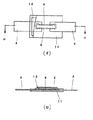
図1の(イ)は本発明に係る合金型温度ヒュ−ズの一実施例を示す図面、図1の(ロ)は図1の(イ)におけるロ−ロ断面図である。
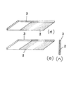
図1において、11はプラスチックベ−スフィルムである。3,3は銅または銅合金の帯状リ−ド導体であり、その先端部裏面をプラスチックベ−スフィルム11の上面に熱プレスで融着してある。このリ−ド導体の後半部の一部または全体には、電池缶体等のニッケル面との溶接を容易に行ない得るように、図2の(イ)または図2の(ロ)及び図2の(ハ)〔図2の(ロ)の正面図〕に示すように、めっき等によるニッケル被覆2を施してある。
4は低融点可溶合金片であり、リ−ド導体先端部の銅または銅合金表面を研磨しその研磨銅表面に低融点可溶合金片端を溶着してある。5は低融点可溶合金片に塗布したフラックス、12はプラスチックベ−スフィルム11の表面上に配したプラスチックカバ−フィルムであり、プラスチックカバ−フィルムの周辺のフィルム間及びプラスチックカバ−フィルムと帯状リ−ド導体との間を熱プレスや超音波融着或いは接着剤等で封止してある。
【0014】
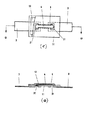
図3の(イ)は、本発明に係る温度ヒュ−ズの別実施例を示す図面、図3の(ロ)は図3の(イ)におけるロ−ロ断面図である。
図3において、3,3は前記と同じく銅または銅合金の帯状リ−ド導体を示し、後半部の一部または全体には、電池缶体等のニッケル面との溶接を容易に行ない得るように、めっき等によるニッケル被覆を施してあり、先端部を熱プレス等でプラスチックベ−スフィルム11にその裏面側から表面側に表出させて融着し、次いで、これらの帯状リ−ド導体先端部の表出部31,31を研磨し、その研磨面に低融点可溶合金片4を溶着し、低融点可溶合金片4にフラックス5を塗布し、プラスチックカバ−フィルム12でフラックス塗布低融点可溶合金片を封止してある。
【0015】
本発明において、リ−ド導体の研磨した銅または銅合金表面への低融点可溶合金片の溶着は、研磨後酸化膜が実質上再生されない早期に行われ、その研磨領域は溶着部を包含する範囲内であれば適宜の範囲に設定できる。
上記銅または銅合金帯状導体のニッケル被覆領域は溶接箇所を包含する範囲であればよく、またニッケル被覆は不被覆部をマスキングし残部をニッケルめっきすることによって施すことができる。
上記ニッケル被覆の厚みは、0.1μm〜10μmとされる。
【0016】
本発明に係る合金型温度ヒュ−ズは二次電池、特にリチウムイオン二次電池の異常発熱の防止に好適に使用できる。
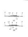
図4は、上記図1に示した合金型温度ヒュ−ズの使用状態の一例を示し、aは正極であるキャツプaに対して部位bで絶縁分離された負極のでニッケル缶体を示し、この缶体a上の絶縁膜cを局部的に剥離し、その露出缶体面に合金型温度ヒュ−ズの本体Aと一方のリ−ド導体311のニッケル被覆面とを接触させ、この接触面を抵抗溶接等で溶接し、キャツプaの正極端子と合金型温度ヒュ−ズの他方のリ−ド導体312とを二端子として携帯機器の負荷に電気的に接続する構成である。
【0017】
而して、一方のリ−ド導体311と缶体bとの溶接がニッケル同士の溶接であるために容易に行うことができる。
また、リ−ド導体の主体が銅または銅合金であり、これらの熱伝導率がニッケルに較べて相当に高いから(銅の熱伝導率403w/m.kに対しニッケルの熱伝導率は94w/m.k)、電池の発生熱をリ−ド導体を経て温度ヒュ−ズの低融点可溶合金片に効率良く伝達でき優れた感熱性を保証できる。
更に、リ−ド導体先端部の銅または銅合金表面を研磨したうえでその研磨面に低融点可溶合金片端を溶着してあるから、低融点可溶合金片の溶着界面の抵抗値を充分に低くでき、また、溶着性の向上により界面溶着強度を高くでき(溶着は抵抗溶接、レザ−溶接等により行うが、研磨表面には酸化物等の異質物質が存在しないから、溶着部への異質物質の巻き込みを排除でき、低抵抗値で優れた機械的強度を保証できる)、低融点可溶合金片の断面積を安定に維持できる。従って、溶着部を含めた低融点可溶合金片の抵抗値を充分に低くでき、定格電流値を大きく設定しても、低融点可溶合金片の自己発熱を防止して所定の温度で適確に作動させ得る。
更にまた、封止とフラックス塗布との二重の酸化防止機構により、銅または銅合金の研磨表面の後発的酸化をよく防止できるから、溶融した低融点可溶合金の研磨導体表面への濡れをよく保証でき、温度ヒュ−ズの作動時、溶融した低融点可溶合金が溶融フラックスとの共存下で銅または銅合金表面によく濡れさせて迅速に分断させ得る。
【0018】
従って、高度の感熱性、リ−ド導体の電池缶体への溶接容易性を保証でき、更に定格電流値を高く設定しても、低融点可溶合金片の自己発熱をよく抑えて低融点可溶合金片の融点で規制された温度で適確に作動させることができる。
更に、温度ヒュ−ズの薄型・小型のために温度ヒュ−ズ装着電池の外形寸法もほぼ元のままに維持でき、リチウムイオン二次電池の異常発熱の防止に好適である。
【0019】
本発明に係る合金型温度ヒュ−ズを上記のように二次電池の異常発熱の未然防止に使用する場合、二次電池の内部短絡などにより異常電流が流れると、その異常電流による低融点可溶合金片のジュ−ル発熱・溶断で通電を遮断させること、すなわち電流温度ヒュ−ズとしても機能させることができる。
また、低融点可溶合金片の近傍に抵抗体を取付け、温度以外の異常例えば二次電池過充電時の電圧上昇を検知して抵抗体を通電発熱させ、この通電発熱で低融点可溶合金片を溶断させること、すなわち異常昇温とこれ以外の異常との双方で温度ヒュ−ズを作動させることもできる。
【0020】
上記した通り本発明に係る合金型温度ヒュ−ズでは、定格電流値を相当に高く設定できる。この定格電流は、0.1A〜15A、好ましくは1.5A〜15Aに設定され、この場合、低融点可溶合金片には抵抗値45mΩ以下、好ましくは15mΩ以下、特に好ましくは2mΩ以下のものが使用され、上記電極表面の研磨のために、低融点可溶合金片の断面寸法(丸線の場合は直径、リボンの場合は厚み)50μm〜800μmのもとでリ−ド導体と電極及び低融点可溶合金片を経る抵抗値を充分に低くでき(低融点可溶合金片の抵抗値45mΩ以下に対しては20mΩ以下、低融点可溶合金片の抵抗値15mΩ以下に対しては20mΩ以下、低融点可溶合金片の抵抗値2mΩ以下に対しては12mΩ以下)、低融点可溶合金片の自己発熱をよく防止して合金型温度ヒュ−ズを低融点可溶合金片の融点で規制された正確な温度で作動させ得る。また、低融点可溶合金片の断面寸法(丸線の場合は直径、リボンの場合は厚み)を350μm以下にして合金型温度ヒュ−ズの一層の薄厚化を図ることも可能となる。
【0021】
上記低融点可溶合金片には、固相線温度が80℃〜120℃、固相線温度が80℃〜120℃である合金、例えばIn30〜75重量%、Sn5〜50重量%、Cd0.5〜25重量%の合金、更にこの合金組成にAu、Ag、Cu、Al、Biのうちの1種または2種以上を合計0.1〜5重量%添加した合金、Bi48〜53重量%、Pb28〜33重量%、Sn13〜19重量%の合金、In0.5〜4重量%、Bi50〜54重量%、Pb30〜34重量%、Sn14〜18重量%の合金等を使用できる。
【0022】
上記低融点可溶合金片に塗布するフラックスは、研磨したリ−ド導体先端部表面を無酸化状態に保持して溶融した低融点可溶合金片の濡れを促しつつ球状化分断を促進する作用を呈し、天然ロジン、変性ロジン(水添ロジン、不均化ロジン、重合ロジン等)及びこれらの精製ロジンにジエチルアミンの塩酸塩、ジエチルアミンの臭化水素酸塩等を添加したものを使用できる。
【0023】
上記プラスチックフィルムには、厚み5μm〜260μm好ましくは160μm〜210μmの熱可塑性樹脂フィルムを使用できる。例えば、ポリエチレンテレフタレ−ト、ポリアミド、ポリイミド、ポリブチレンテレフタレ−ト、ポリフェニレンオキシド、ポリエチレンサルファイド、ポリサルホン等のエンジニアリングプラスチック、ホリアセタ−ル、ポリカ−ボネ−ト、ポリフェニレンスルフィド、ポリオキシベンゾイル、ポリエ−テルエ−テルレトン、ポリエ−テルイミド等のエンジニアリングプラスチックやポリ塩化ビニル、ポリ酢酸ビニル、ポリメチルメタクリレ−ト、ポリ塩化ビニリデン、ポリテトラフルオロエチレン、エチレンポリテトラフルオロエチレン共重合体、エチレン酢酸ビニル共重合体(EVA、AS樹脂、ABS樹脂、アイオノマ−、AAS樹脂、ACS樹脂等)の中から選択される。
【0024】
【発明の効果】
本発明に係る合金型温度ヒュ−ズにおいては、相手ニッケル面とリ−ド導体との溶接をリ−ド導体のニッケル被覆面において行うことができるから、その溶接を容易に行うことができ、また、リ−ド導体の主材を銅または銅合金としているから、リ−ド導体を経ての温度ヒュ−ズの低融点可溶合金片への熱伝達を効率良く行わせ得る。さらに、リ−ド導体先端部の銅または銅合金表面を研磨して低融点可溶合金片を溶着してあるから、その溶着界面を充分に低抵抗にでき高い定格電流値のもとでも自己発熱を排除して適確な温度で作動させ得る。
従って、缶体がニッケルであり、かつ常時電流がその大なる蓄積エネルギ−のために高く設定されるリチウムイオン二次電池の異常発熱の未然防止に極めて有用である。
【図面の簡単な説明】
【図1】本発明に係る合金型温度ヒュ−ズの一実施例を示す図面である。
【図2】本発明において使用する帯状リ−ド導体を示す図面である。
【図3】本発明に係る合金型温度ヒュ−ズの別実施例を示す図面である。
【図4】本発明に係る合金型温度ヒュ−ズの使用状態を示す図面である。
【図5】従来例を示す図面である。
【符号の説明】
11 プラスチックベ−スフィルム
2 ニッケル被覆
3 帯状リ−ド導体
4 低融点可溶合金片
5 フラックス
12 プラスチックカバ−フィルム[0001]
BACKGROUND OF THE INVENTION
The present invention relates to an alloy type temperature fuse, and is useful for preventing abnormal temperature rise in a lithium ion secondary battery or the like.
[0002]
[Prior art]
Recently, a battery that can be repeatedly charged and discharged, that is, a secondary battery, has been used as a power source for portable electronic devices such as a mobile phone, a PHS, and a portable personal computer.
As this secondary battery, a lithium ion secondary battery is attracting attention because of its high energy density, long life cycle, high operating voltage, and the like. In this lithium ion secondary battery or the like, if energy is released at a stroke for some reason, the battery may be heated to an abnormally high temperature and explode.
Therefore, the temperature fuse is closely attached to a can such as a lithium ion secondary battery, and is attached so as to be inserted in series between the positive electrode and the negative electrode of the battery, so that the battery reaches a predetermined upper limit temperature. It has been proposed to electrically disconnect the battery circuit when reached.
[0003]
One condition required for the secondary battery temperature fuse is a thin and small temperature fuse. As such a thin and small temperature fuse, an alloy type temperature fuse shown in FIG. 5 is known.
[0004]
In the alloy type temperature fuse shown in FIG. 5 (a), the tips of a pair of strip-
[0005]
In the alloy-type temperature fuse shown in FIG. 5 (b), the tip portions of the pair of strip-
[0006]
Further, other conditions required for the temperature fuse for the secondary battery include that the lead conductor is made of the same material as that of the can so that it can be easily welded to the can of the secondary battery, such as nickel. To do.
However, nickel is a metal that is difficult to solder, and if the lead conductor is nickel in the above alloy type temperature fuse, it is difficult to join the low melting point soluble alloy piece at the lead conductor tip. It becomes.
[0007]
Therefore, it has been proposed to provide a copper conductor on the surface of the tip of the nickel lead conductor by clad copper foil, copper plating or the like, and weld one end of a low melting point soluble alloy to this copper conductor (Japanese Patent Laid-Open No. 11-40026). issue).
[0008]
[Problems to be solved by the invention]
However, since nickel has a lower thermal conductivity than copper (about 1/4 times), the nickel lead conductor with copper on the tip surface is mainly made of nickel. The transmission efficiency is inferior compared to the case of using a copper lead conductor, and a considerable decrease in heat sensitivity is inevitable.
[0009]
In the lithium ion secondary battery and the like, the rated current can be set high because of its high energy density, but the leading end of the lead conductor is heat-sealed to a plastic base film. In the above-mentioned alloy type temperature fuse, oxidation of the copper conductor surface at the lead conductor tip is promoted for heating, or adhesion of foreign matters eluted from the plastic base film by heating occurs. As a result, the resistance value at the weld interface between the copper conductor surface and the low melting point soluble alloy piece increases. As a result, if the rated current is set high, there is a concern about operating errors due to heat generated by the normal current at the high resistance part. The
[0010]
Accordingly, in the above thin and small alloy type temperature fuse, the lead conductor is made of the same material as the can of the secondary battery to facilitate the welding attachment, and the lead conductor is easily soldered to the tip. By simply providing an attachment conductor and facilitating the joining of the lead conductor and the low melting point soluble alloy piece, it is not possible to obtain a high current rating based on the high energy density of a lithium ion secondary battery. It is difficult to ensure accurate prevention of secondary battery abnormal heat generation.
[0011]
SUMMARY OF THE INVENTION An object of the present invention is to provide a thin and small alloy-type temperature fuse that is easy to weld between a lead conductor and a nickel mating surface and that is excellent in heat transfer through the lead conductor. is there.
It is another object of the present invention to provide an alloy type temperature fuse that can be suitably used to prevent abnormal temperature rise in a secondary battery having a high energy density such as a lithium ion secondary battery.
[0012]
[Means for solving the problems]
One alloy-type thermal fuse according to the present invention is an alloy-type temperature fuse in which a lead conductor is welded to a battery can, and the tip portions of a pair of strip-shaped lead conductors are on the surface of a plastic base film. fused low-melting fusible alloy piece is connected between the tip portion, the flux is applied to the low-melting fusible alloy piece, the flux coating a low-melting fusible alloy piece is sealed, the strip lead conductors, after A copper or copper alloy strip having a nickel coating applied to at least a part of the end portion is used. Another alloy type thermal fuse according to the present invention has a lead conductor as a battery. This is an alloy-type temperature fuse that is welded to a can body, and the tip of a pair of strip-shaped lead conductors appears watertight on the surface from the back surface of the plastic base film, and between the lead conductor and the plastic base film. Is fused Is, low-melting fusible alloy piece is connected between the revealing conductors, a flux in the low-melting fusible alloy piece is applied, the flux coating a low-melting fusible alloy piece is sealed, the strip lead conductors, a rear end portion A copper or copper alloy strip having a nickel coating applied to at least a part of the copper or copper alloy is used. In any configuration, the surface of the copper or copper alloy at the tip of the strip lead conductor is polished. It is possible to weld one end of a low melting point soluble alloy to the polished surface and set the rated current value to 0.1A to 15A.
[0013]
DETAILED DESCRIPTION OF THE INVENTION
Hereinafter, embodiments of the present invention will be described with reference to the drawings.
FIG. 1 (a) is a drawing showing an embodiment of an alloy type temperature fuse according to the present invention, and FIG. 1 (b) is a cross-sectional view of FIG.
In FIG. 1, 11 is a plastic base film.
[0014]
3 (a) is a drawing showing another embodiment of the temperature fuse according to the present invention, and FIG. 3 (b) is a cross-sectional view of FIG. 3 (b).
3,
[0015]
In the present invention, the welding of the low melting point soluble alloy piece to the polished copper or copper alloy surface of the lead conductor is performed at an early stage where the oxide film is not substantially regenerated after polishing, and the polished region includes the welded portion. If it is within the range, it can be set to an appropriate range.
The nickel-coated region of the copper or copper alloy strip conductor may be in a range that includes the welded portion, and the nickel coating can be applied by masking the uncoated portion and nickel-plating the remaining portion.
The nickel coating has a thickness of 0.1 μm to 10 μm.
[0016]
The alloy type temperature fuse according to the present invention can be suitably used for preventing abnormal heat generation of a secondary battery, particularly a lithium ion secondary battery.
FIG. 4 shows an example of the usage state of the alloy-type temperature fuse shown in FIG. 1, wherein a is a negative electrode that is insulated and separated at a portion b with respect to a cap a that is a positive electrode. The insulating film c on the can body a is locally peeled, and the exposed can body surface is brought into contact with the main body A of the alloy-type temperature fuse and the nickel-coated surface of one of the
[0017]
Thus, the welding of one of the
Further, the lead conductor is mainly copper or copper alloy, and their thermal conductivity is considerably higher than that of nickel (the thermal conductivity of nickel is 94 w / mk compared to the thermal conductivity of copper 403 w / mk). ), Heat generated from the battery can be efficiently transferred to the low melting point soluble alloy piece having a temperature fuse through the lead conductor, and excellent heat sensitivity can be ensured.
Furthermore, since the copper or copper alloy surface of the lead conductor tip is polished and the low melting point soluble alloy piece end is welded to the polished surface, the resistance value of the welding interface of the low melting point soluble alloy piece is sufficient. In addition, it is possible to increase the interfacial weld strength by improving the weldability (welding is performed by resistance welding, laser welding, etc., but there are no foreign substances such as oxides on the polished surface. The inclusion of foreign substances can be eliminated, and excellent mechanical strength can be ensured with a low resistance value), and the cross-sectional area of the low melting point soluble alloy piece can be maintained stably. Accordingly, the resistance value of the low melting point soluble alloy piece including the welded portion can be sufficiently lowered, and even if the rated current value is set large, the low melting point soluble alloy piece is prevented from self-heating and suitable at a predetermined temperature. Can work reliably.
Furthermore, since the double oxidation prevention mechanism of sealing and flux coating can prevent the subsequent oxidation of the polished surface of copper or copper alloy well, the molten low melting point soluble alloy can be wetted on the polished conductor surface. During operation of the temperature fuse, the molten low melting point soluble alloy can be wetted well on the copper or copper alloy surface in the presence of the molten flux and can be quickly divided.
[0018]
Therefore, it is possible to guarantee a high degree of heat sensitivity and ease of welding of the lead conductor to the battery can body, and even if the rated current value is set high, the self-heating of the low melting point soluble alloy piece is well suppressed and the low melting point. It can be accurately operated at a temperature regulated by the melting point of the soluble alloy piece.
Furthermore, since the temperature fuse is thin and small, the external dimensions of the battery with the temperature fuse can be maintained almost unchanged, which is suitable for preventing abnormal heat generation of the lithium ion secondary battery.
[0019]
When the alloy type temperature fuse according to the present invention is used to prevent abnormal heat generation of the secondary battery as described above, if an abnormal current flows due to an internal short circuit of the secondary battery, the low melting point due to the abnormal current is allowed. It is possible to function as a current temperature fuse by interrupting energization by the juule heat generation / melting of the molten alloy piece.
In addition, a resistor is attached in the vicinity of the low melting point soluble alloy piece, and an abnormality other than temperature, for example, a voltage rise at the time of secondary battery overcharge is detected and the resistor is heated by heating. It is also possible to operate the temperature fuse by fusing the piece, that is, both abnormal temperature rise and other abnormalities.
[0020]
As described above, in the alloy type temperature fuse according to the present invention, the rated current value can be set considerably high. The rated current is set to 0.1 A to 15 A, preferably 1.5 A to 15 A. In this case, the low melting point soluble alloy piece has a resistance value of 45 mΩ or less, preferably 15 mΩ or less, particularly preferably 2 mΩ or less. In order to polish the electrode surface, the lead conductor, the electrode, and the cross-sectional dimension of the low melting point soluble alloy piece (diameter in the case of a round wire, thickness in the case of a ribbon) 50 μm to 800 μm are used. The resistance value passing through the low melting point soluble alloy piece can be sufficiently reduced (20 mΩ or less for the low melting point soluble alloy piece of 45 mΩ or less, 20 mΩ for the low melting point soluble alloy piece of 15 mΩ or less. Hereinafter, the resistance value of the low melting point soluble alloy piece is 12 mΩ or less for the resistance value of 2 mΩ or less). Can be operated at the exact temperature regulated by . Further, it is possible to further reduce the thickness of the alloy type temperature fuse by setting the cross-sectional dimension of the low melting point soluble alloy piece (diameter in the case of a round wire and thickness in the case of a ribbon) to 350 μm or less.
[0021]
The low melting point soluble alloy piece includes an alloy having a solidus temperature of 80 ° C to 120 ° C and a solidus temperature of 80 ° C to 120 ° C, such as In 30 to 75 wt%,
[0022]
The flux applied to the low-melting-point soluble alloy piece promotes spheroidization while promoting the wetting of the molten low-melting-point soluble alloy piece while maintaining the polished lead conductor tip surface in an unoxidized state. In addition, natural rosin, modified rosin (hydrogenated rosin, disproportionated rosin, polymerized rosin, etc.) and those purified rosin added with diethylamine hydrochloride, diethylamine hydrobromide, etc. can be used.
[0023]
As the plastic film, a thermoplastic resin film having a thickness of 5 μm to 260 μm, preferably 160 μm to 210 μm can be used. For example, engineering plastics such as polyethylene terephthalate, polyamide, polyimide, polybutylene terephthalate, polyphenylene oxide, polyethylene sulfide, polysulfone, horiacetal, polycarbonate, polyphenylene sulfide, polyoxybenzoyl, polyethylene Engineering plastics such as terether-terleton and polyetherimide, polyvinyl chloride, polyvinyl acetate, polymethyl methacrylate, polyvinylidene chloride, polytetrafluoroethylene, ethylene polytetrafluoroethylene copolymer, ethylene vinyl acetate copolymer It is selected from coalescence (EVA, AS resin, ABS resin, ionomer, AAS resin, ACS resin, etc.).
[0024]
【The invention's effect】
In the alloy type temperature fuse according to the present invention, since the welding between the mating nickel surface and the lead conductor can be performed on the nickel-coated surface of the lead conductor, the welding can be easily performed, Moreover, since the main material of the lead conductor is copper or a copper alloy, the heat transfer to the low melting point soluble alloy piece of the temperature fuse through the lead conductor can be efficiently performed. Furthermore, the copper or copper alloy surface at the tip of the lead conductor is polished and welded with a low melting point soluble alloy piece, so that the welding interface can be made sufficiently low in resistance, even under a high rated current value. It can be operated at an appropriate temperature by eliminating heat generation.
Therefore, it is extremely useful for preventing abnormal heat generation of a lithium ion secondary battery in which the can body is nickel and the constant current is set high due to its large stored energy.
[Brief description of the drawings]
FIG. 1 is a view showing an embodiment of an alloy type temperature fuse according to the present invention.
FIG. 2 is a drawing showing a strip-shaped lead conductor used in the present invention.
FIG. 3 is a drawing showing another embodiment of an alloy type temperature fuse according to the present invention.
FIG. 4 is a view showing a usage state of an alloy type temperature fuse according to the present invention.
FIG. 5 is a diagram showing a conventional example.
[Explanation of symbols]
11
Claims (6)
Priority Applications (1)
| Application Number | Priority Date | Filing Date | Title |
|---|---|---|---|
| JP17957999A JP4209552B2 (en) | 1999-06-25 | 1999-06-25 | Alloy type temperature fuse |
Applications Claiming Priority (1)
| Application Number | Priority Date | Filing Date | Title |
|---|---|---|---|
| JP17957999A JP4209552B2 (en) | 1999-06-25 | 1999-06-25 | Alloy type temperature fuse |
Publications (2)
| Publication Number | Publication Date |
|---|---|
| JP2001006508A JP2001006508A (en) | 2001-01-12 |
| JP4209552B2 true JP4209552B2 (en) | 2009-01-14 |
Family
ID=16068204
Family Applications (1)
| Application Number | Title | Priority Date | Filing Date |
|---|---|---|---|
| JP17957999A Expired - Fee Related JP4209552B2 (en) | 1999-06-25 | 1999-06-25 | Alloy type temperature fuse |
Country Status (1)
| Country | Link |
|---|---|
| JP (1) | JP4209552B2 (en) |
Families Citing this family (5)
| Publication number | Priority date | Publication date | Assignee | Title |
|---|---|---|---|---|
| JP4507409B2 (en) * | 2001-01-18 | 2010-07-21 | パナソニック株式会社 | Thermal fuse |
| JP4290426B2 (en) * | 2001-02-20 | 2009-07-08 | パナソニック株式会社 | Thermal fuse |
| JP5867043B2 (en) * | 2011-12-12 | 2016-02-24 | パナソニックIpマネジメント株式会社 | Thermal fuse and manufacturing method thereof |
| CN103367690A (en) * | 2012-04-05 | 2013-10-23 | 松下电器产业株式会社 | Temperature fuse and manufacturing method thereof |
| CN108597958B (en) * | 2018-06-11 | 2023-09-01 | 佛山市高明欧一电子制造有限公司 | Adjustable temperature controller with disposable overheat protection |
-
1999
- 1999-06-25 JP JP17957999A patent/JP4209552B2/en not_active Expired - Fee Related
Also Published As
| Publication number | Publication date |
|---|---|
| JP2001006508A (en) | 2001-01-12 |
Similar Documents
| Publication | Publication Date | Title |
|---|---|---|
| KR100347232B1 (en) | Thin type thermal fuse and manufacturing method thereof | |
| US9401257B2 (en) | Circuit protection device | |
| EP1465224B1 (en) | Thermal fuse having a function of a current fuse | |
| KR100567883B1 (en) | Thermistor with improved lead structure and secondary battery with this thermistor | |
| JP3618635B2 (en) | Battery protector | |
| JP4341085B2 (en) | Temperature fuse with resistor | |
| JP6027456B2 (en) | Secondary battery pack having a protection circuit | |
| JP4209552B2 (en) | Alloy type temperature fuse | |
| JP2004190113A (en) | Alloy-type thermal fuse and material for thermal fuse element | |
| JP6097637B2 (en) | Secondary battery pack having a protection circuit | |
| JP4297431B2 (en) | Alloy-type thermal fuse and protective device using the same | |
| JP4209549B2 (en) | Alloy type temperature fuse | |
| KR20220034231A (en) | Protection element, battery pack | |
| JP2012129124A (en) | Circuit protective element and battery pack device using the same | |
| CN217562508U (en) | Novel protection device | |
| JP2000090792A (en) | Alloy type thermal fuse | |
| JP4097792B2 (en) | Thin temperature fuse | |
| JP4610807B2 (en) | Thin fuse | |
| CN211929597U (en) | Sampling line and battery pack | |
| JP4368039B2 (en) | Thermal fuse having a self-heating element and a battery pack incorporating the thermal fuse | |
| JPH11339615A (en) | Substrate type resistor thermal fuse | |
| JP2003045305A (en) | Thin fuse | |
| JP2000322994A (en) | Alloy-type temperature fuse | |
| JP2000123694A (en) | Thin type thermal/current fuse | |
| JPS6314356Y2 (en) |
Legal Events
| Date | Code | Title | Description |
|---|---|---|---|
| A621 | Written request for application examination |
Free format text: JAPANESE INTERMEDIATE CODE: A621 Effective date: 20060202 |
|
| A977 | Report on retrieval |
Free format text: JAPANESE INTERMEDIATE CODE: A971007 Effective date: 20080821 |
|
| A131 | Notification of reasons for refusal |
Free format text: JAPANESE INTERMEDIATE CODE: A131 Effective date: 20080902 |
|
| A521 | Written amendment |
Free format text: JAPANESE INTERMEDIATE CODE: A523 Effective date: 20080919 |
|
| TRDD | Decision of grant or rejection written | ||
| A01 | Written decision to grant a patent or to grant a registration (utility model) |
Free format text: JAPANESE INTERMEDIATE CODE: A01 Effective date: 20081021 |
|
| A01 | Written decision to grant a patent or to grant a registration (utility model) |
Free format text: JAPANESE INTERMEDIATE CODE: A01 |
|
| A61 | First payment of annual fees (during grant procedure) |
Free format text: JAPANESE INTERMEDIATE CODE: A61 Effective date: 20081023 |
|
| R150 | Certificate of patent or registration of utility model |
Free format text: JAPANESE INTERMEDIATE CODE: R150 |
|
| FPAY | Renewal fee payment (event date is renewal date of database) |
Free format text: PAYMENT UNTIL: 20111031 Year of fee payment: 3 |
|
| LAPS | Cancellation because of no payment of annual fees |