JP4207828B2 - Electronic components - Google Patents
Electronic components Download PDFInfo
- Publication number
- JP4207828B2 JP4207828B2 JP2004112860A JP2004112860A JP4207828B2 JP 4207828 B2 JP4207828 B2 JP 4207828B2 JP 2004112860 A JP2004112860 A JP 2004112860A JP 2004112860 A JP2004112860 A JP 2004112860A JP 4207828 B2 JP4207828 B2 JP 4207828B2
- Authority
- JP
- Japan
- Prior art keywords
- resin
- lead
- circuit board
- lead wire
- case
- Prior art date
- Legal status (The legal status is an assumption and is not a legal conclusion. Google has not performed a legal analysis and makes no representation as to the accuracy of the status listed.)
- Expired - Lifetime
Links
- 229920005989 resin Polymers 0.000 claims description 59
- 239000011347 resin Substances 0.000 claims description 59
- WABPQHHGFIMREM-UHFFFAOYSA-N lead(0) Chemical compound [Pb] WABPQHHGFIMREM-UHFFFAOYSA-N 0.000 claims description 46
- 238000003860 storage Methods 0.000 description 16
- 230000004048 modification Effects 0.000 description 10
- 238000012986 modification Methods 0.000 description 10
- 239000000758 substrate Substances 0.000 description 8
- 239000011248 coating agent Substances 0.000 description 7
- 238000000576 coating method Methods 0.000 description 7
- 239000000853 adhesive Substances 0.000 description 4
- 230000001070 adhesive effect Effects 0.000 description 4
- 230000007547 defect Effects 0.000 description 4
- 238000000034 method Methods 0.000 description 4
- 239000000565 sealant Substances 0.000 description 4
- 239000003822 epoxy resin Substances 0.000 description 3
- 229920000647 polyepoxide Polymers 0.000 description 3
- 238000005476 soldering Methods 0.000 description 3
- 238000005452 bending Methods 0.000 description 2
- 238000001514 detection method Methods 0.000 description 2
- 229920001707 polybutylene terephthalate Polymers 0.000 description 2
- 238000003825 pressing Methods 0.000 description 2
- 238000007789 sealing Methods 0.000 description 2
- 229910001369 Brass Inorganic materials 0.000 description 1
- 229910000570 Cupronickel Inorganic materials 0.000 description 1
- 239000004593 Epoxy Substances 0.000 description 1
- 229910001030 Iron–nickel alloy Inorganic materials 0.000 description 1
- 229910045601 alloy Inorganic materials 0.000 description 1
- 239000000956 alloy Substances 0.000 description 1
- 239000010951 brass Substances 0.000 description 1
- 239000003795 chemical substances by application Substances 0.000 description 1
- 239000004020 conductor Substances 0.000 description 1
- YOCUPQPZWBBYIX-UHFFFAOYSA-N copper nickel Chemical compound [Ni].[Cu] YOCUPQPZWBBYIX-UHFFFAOYSA-N 0.000 description 1
- 238000005336 cracking Methods 0.000 description 1
- 238000009826 distribution Methods 0.000 description 1
- 230000005611 electricity Effects 0.000 description 1
- 230000001678 irradiating effect Effects 0.000 description 1
- 238000010030 laminating Methods 0.000 description 1
- 239000002184 metal Substances 0.000 description 1
- 229910052751 metal Inorganic materials 0.000 description 1
- 230000003287 optical effect Effects 0.000 description 1
- 229910000889 permalloy Inorganic materials 0.000 description 1
- -1 polybutylene terephthalate Polymers 0.000 description 1
- 230000035939 shock Effects 0.000 description 1
- 238000005549 size reduction Methods 0.000 description 1
- 238000009281 ultraviolet germicidal irradiation Methods 0.000 description 1
Images
Classifications
-
- H—ELECTRICITY
- H05—ELECTRIC TECHNIQUES NOT OTHERWISE PROVIDED FOR
- H05K—PRINTED CIRCUITS; CASINGS OR CONSTRUCTIONAL DETAILS OF ELECTRIC APPARATUS; MANUFACTURE OF ASSEMBLAGES OF ELECTRICAL COMPONENTS
- H05K3/00—Apparatus or processes for manufacturing printed circuits
- H05K3/30—Assembling printed circuits with electric components, e.g. with resistor
- H05K3/32—Assembling printed circuits with electric components, e.g. with resistor electrically connecting electric components or wires to printed circuits
- H05K3/34—Assembling printed circuits with electric components, e.g. with resistor electrically connecting electric components or wires to printed circuits by soldering
- H05K3/3405—Edge mounted components, e.g. terminals
-
- H—ELECTRICITY
- H01—ELECTRIC ELEMENTS
- H01R—ELECTRICALLY-CONDUCTIVE CONNECTIONS; STRUCTURAL ASSOCIATIONS OF A PLURALITY OF MUTUALLY-INSULATED ELECTRICAL CONNECTING ELEMENTS; COUPLING DEVICES; CURRENT COLLECTORS
- H01R13/00—Details of coupling devices of the kinds covered by groups H01R12/70 or H01R24/00 - H01R33/00
- H01R13/46—Bases; Cases
- H01R13/52—Dustproof, splashproof, drip-proof, waterproof, or flameproof cases
- H01R13/5216—Dustproof, splashproof, drip-proof, waterproof, or flameproof cases characterised by the sealing material, e.g. gels or resins
-
- H—ELECTRICITY
- H05—ELECTRIC TECHNIQUES NOT OTHERWISE PROVIDED FOR
- H05K—PRINTED CIRCUITS; CASINGS OR CONSTRUCTIONAL DETAILS OF ELECTRIC APPARATUS; MANUFACTURE OF ASSEMBLAGES OF ELECTRICAL COMPONENTS
- H05K5/00—Casings, cabinets or drawers for electric apparatus
- H05K5/0091—Housing specially adapted for small components
-
- H—ELECTRICITY
- H01—ELECTRIC ELEMENTS
- H01R—ELECTRICALLY-CONDUCTIVE CONNECTIONS; STRUCTURAL ASSOCIATIONS OF A PLURALITY OF MUTUALLY-INSULATED ELECTRICAL CONNECTING ELEMENTS; COUPLING DEVICES; CURRENT COLLECTORS
- H01R13/00—Details of coupling devices of the kinds covered by groups H01R12/70 or H01R24/00 - H01R33/00
- H01R13/40—Securing contact members in or to a base or case; Insulating of contact members
- H01R13/405—Securing in non-demountable manner, e.g. moulding, riveting
-
- H—ELECTRICITY
- H01—ELECTRIC ELEMENTS
- H01R—ELECTRICALLY-CONDUCTIVE CONNECTIONS; STRUCTURAL ASSOCIATIONS OF A PLURALITY OF MUTUALLY-INSULATED ELECTRICAL CONNECTING ELEMENTS; COUPLING DEVICES; CURRENT COLLECTORS
- H01R43/00—Apparatus or processes specially adapted for manufacturing, assembling, maintaining, or repairing of line connectors or current collectors or for joining electric conductors
- H01R43/20—Apparatus or processes specially adapted for manufacturing, assembling, maintaining, or repairing of line connectors or current collectors or for joining electric conductors for assembling or disassembling contact members with insulating base, case or sleeve
- H01R43/24—Assembling by moulding on contact members
-
- H—ELECTRICITY
- H05—ELECTRIC TECHNIQUES NOT OTHERWISE PROVIDED FOR
- H05K—PRINTED CIRCUITS; CASINGS OR CONSTRUCTIONAL DETAILS OF ELECTRIC APPARATUS; MANUFACTURE OF ASSEMBLAGES OF ELECTRICAL COMPONENTS
- H05K2201/00—Indexing scheme relating to printed circuits covered by H05K1/00
- H05K2201/10—Details of components or other objects attached to or integrated in a printed circuit board
- H05K2201/10227—Other objects, e.g. metallic pieces
- H05K2201/10287—Metal wires as connectors or conductors
-
- H—ELECTRICITY
- H05—ELECTRIC TECHNIQUES NOT OTHERWISE PROVIDED FOR
- H05K—PRINTED CIRCUITS; CASINGS OR CONSTRUCTIONAL DETAILS OF ELECTRIC APPARATUS; MANUFACTURE OF ASSEMBLAGES OF ELECTRICAL COMPONENTS
- H05K2201/00—Indexing scheme relating to printed circuits covered by H05K1/00
- H05K2201/10—Details of components or other objects attached to or integrated in a printed circuit board
- H05K2201/10227—Other objects, e.g. metallic pieces
- H05K2201/10386—Clip leads; Terminals gripping the edge of a substrate
-
- H—ELECTRICITY
- H05—ELECTRIC TECHNIQUES NOT OTHERWISE PROVIDED FOR
- H05K—PRINTED CIRCUITS; CASINGS OR CONSTRUCTIONAL DETAILS OF ELECTRIC APPARATUS; MANUFACTURE OF ASSEMBLAGES OF ELECTRICAL COMPONENTS
- H05K2201/00—Indexing scheme relating to printed circuits covered by H05K1/00
- H05K2201/10—Details of components or other objects attached to or integrated in a printed circuit board
- H05K2201/10613—Details of electrical connections of non-printed components, e.g. special leads
- H05K2201/10954—Other details of electrical connections
- H05K2201/10962—Component not directly connected to the PCB
-
- H—ELECTRICITY
- H05—ELECTRIC TECHNIQUES NOT OTHERWISE PROVIDED FOR
- H05K—PRINTED CIRCUITS; CASINGS OR CONSTRUCTIONAL DETAILS OF ELECTRIC APPARATUS; MANUFACTURE OF ASSEMBLAGES OF ELECTRICAL COMPONENTS
- H05K2201/00—Indexing scheme relating to printed circuits covered by H05K1/00
- H05K2201/10—Details of components or other objects attached to or integrated in a printed circuit board
- H05K2201/10613—Details of electrical connections of non-printed components, e.g. special leads
- H05K2201/10954—Other details of electrical connections
- H05K2201/10977—Encapsulated connections
Landscapes
- Engineering & Computer Science (AREA)
- Microelectronics & Electronic Packaging (AREA)
- Chemical & Material Sciences (AREA)
- Dispersion Chemistry (AREA)
- Manufacturing & Machinery (AREA)
- Connector Housings Or Holding Contact Members (AREA)
- Casings For Electric Apparatus (AREA)
Description
本発明は、回路基板とこれを収納するケースと入出力用のリード線とを備えた電子部品係り、特に、樹脂の充填により、ケースにリード線を固定する構成を有する電子部品に関する。 The present invention relates to an electronic component including a circuit board, a case for housing the circuit board, and an input / output lead wire, and more particularly to an electronic component having a configuration in which a lead wire is fixed to the case by filling with a resin.
回路基板をケースに収納し、外部との電気的接続を行うリード線を備えた電子部品の一例として、特許文献1に記載されたものがある。
この電子部品は、電線に流れる電流を検出する電流センサであり、ケース内に収納された回路基板に直接はんだ付けされた屈曲性を有する所謂リード線をケース外に引き出し、外部の機器等に接続できるようにしたものである。
As an example of an electronic component including a lead wire that houses a circuit board in a case and is electrically connected to the outside, there is one described in Patent Document 1.
This electronic component is a current sensor that detects the current flowing in the wire. Pull out the so-called flexible lead wire that is directly soldered to the circuit board housed in the case and connect it to external devices. It is something that can be done.
この例では、リード線と回路基板との接続作業において、基板に設けた端子にリードをからげたり、基板に設けた貫通孔にリード線のリードを挿通する必要があって、作業性が良いものではなかった。
そのため、作業性向上のため、回路基板にまずクリップタイプのリード(以下クリップリードと称する)を接続し、このクリップリードの一方の端部にリード線のリードを圧着接続した電子部品がある。回路基板にクリップリードを接続した一例として、特許文献2に記載されたものがある。
Therefore, in order to improve workability, there is an electronic component in which a clip-type lead (hereinafter referred to as a clip lead) is first connected to a circuit board, and a lead wire lead is crimped to one end of the clip lead. One example in which a clip lead is connected to a circuit board is described in
ところで、電子部品に対しては、より安価で小型化したものが求められている。
また、電気を動力として利用した小型輸送車両(例えばハイブリッドカー)が普及するに伴い、耐振動性や耐衝撃性により優れ、信頼性の高い電子部品が要望されている。これは上述の電流センサについてももちろん同様である。
そのため、電子部品を外部機器等に接続するために引き出したリード線に対して、振動や衝撃等により引張り方向の外力が加わった場合に、基板とクリップリードとの接続部や、クリップリードとリード線との接続部に応力が集中して接続不良を発生する場合があった。
特に、後者は前者より接続強度が弱く、不良が発生する頻度が高かった。
By the way, electronic parts are required to be cheaper and smaller.
In addition, as small transport vehicles (for example, hybrid cars) that use electricity as power have become widespread, electronic components that are superior in vibration resistance and shock resistance and have high reliability have been demanded. The same applies to the current sensor described above.
Therefore, when an external force in the pulling direction is applied to the lead wire drawn out to connect an electronic component to an external device, etc. due to vibration or impact, the connection part between the board and the clip lead, or the clip lead and the lead In some cases, stress is concentrated on the connection portion with the wire, resulting in poor connection.
In particular, the latter has a lower connection strength than the former, and the frequency of occurrence of defects is high.
そこで、図9のように、このクリップリード102とリード線103との接続部106をエポキシ等の充填樹脂107で被覆してケース104に固着する構造が考えられたが、この方法では、エポキシ樹脂107を被覆する際に必要以外の部分にエポキシ樹脂107が流れ、この樹脂の硬化後に残留応力が残存したり、残留応力の分布が一様にならないことから、歪みや割れが生じて不良となる場合があった。
また、被覆量が制御できずに必要以上の多量の樹脂で被覆してしまうという問題があった。
さらに、被覆態様がばらつき、その結果、接続部の強度がばらつき、高い信頼性が得られないという問題があった。
Therefore, as shown in FIG. 9, a structure in which the connecting
Further, there is a problem that the coating amount cannot be controlled and the coating is performed with a larger amount of resin than necessary.
Furthermore, there is a problem that the coating mode varies, and as a result, the strength of the connecting portion varies, and high reliability cannot be obtained.
そこで本発明が解決しようとする課題は、リード線を被覆する樹脂が不要部分に流れて発生する不良がなく、適量の樹脂で確実に被覆可能で、高い信頼性が得られる電子部品を提供することにある。 Therefore, the problem to be solved by the present invention is to provide an electronic component that can be reliably coated with an appropriate amount of resin without causing defects that occur when the resin that coats the lead wire flows into the unnecessary portion, and that provides high reliability. There is.
上記の課題を解決するために、本願発明は手段として次の構成を有する。
即ち、請求項1に係る発明は、回路基板(3)と、一端が前記回路基板(3)に接続するリード端子(9)と、一端が前記リード端子(9)の他端側に接続するリード線(8)とを順次配列し、前記回路基板(3)と前記リード端子(9)とをケース(6)内に収納すると共に、前記リード線(8)の他端側を前記ケース外に引き出して成る電子部品であって、
前記ケース(6)に、該ケース(6)内に収納される前記リード端子(9)の他端側と前記リード線(8)の一端側との接続部(8e)を固定する樹脂(10)を充填する樹脂充填部(6B)を形成し、前記リード端子(9)を、前記樹脂充填部(6B)の壁(6b3)を跨いで配置すると共に、前記接続部(8e)及びその近傍を前記樹脂(10)中に固定して成ることを特徴とする電子部品(50)である。
また、請求項2に係る発明は、回路基板(3)と、一端が前記回路基板(3)に接続するリード端子と、一端が前記リード端子の他端側に接続するリード線とを順次配列し、前記回路基板(3)と前記リード端子(9)とをケース(6)内に収納すると共に、前記リード線の他端側を前記ケース(6)外に引き出して成る電子部品であって、
前記ケース(6)に、該ケース(6)内に収納される前記リード端子(9)の他端側と前記リード線の一端側との接続部(8e)を固定する樹脂(10)を充填する樹脂充填部(6B)を形成し、前記リード端子(9)を、前記樹脂充填部(6B)の壁(6b3)に設けた貫通孔(6f)に挿通させると共に、前記接続部(8e)及びその近傍を前記樹脂(10)中に固定して成ることを特徴とする電子部品である。
In order to solve the above problems, the present invention has the following configuration as means.
That is, the invention according to claim 1 is a circuit board (3), a lead terminal (9) having one end connected to the circuit board (3), and one end connected to the other end of the lead terminal (9). The lead wire (8) is sequentially arranged, the circuit board (3) and the lead terminal (9) are accommodated in the case (6), and the other end side of the lead wire (8) is disposed outside the case. Electronic parts drawn out in
Resin (10) for fixing a connecting portion (8e) between the other end side of the lead terminal (9) and one end side of the lead wire (8) housed in the case (6) to the case (6). And the lead terminal (9) is disposed across the wall (6b3) of the resin filling portion (6B), and the connection portion (8e) and the vicinity thereof. Is an electronic component (50) characterized by being fixed in the resin (10).
According to a second aspect of the present invention, a circuit board (3), a lead terminal having one end connected to the circuit board (3), and a lead wire having one end connected to the other end of the lead terminal are sequentially arranged. And an electronic component in which the circuit board (3) and the lead terminal (9) are housed in a case (6) and the other end of the lead wire is drawn out of the case (6). ,
The case (6) is filled with a resin (10) for fixing a connecting portion (8e) between the other end side of the lead terminal (9) housed in the case (6) and one end side of the lead wire. The resin filling portion (6B) is formed, and the lead terminal (9) is inserted through the through hole (6f) provided in the wall (6b3) of the resin filling portion (6B) and the connection portion (8e). And the vicinity thereof is fixed in the resin (10).
本願発明によれば、リード線を被覆する樹脂が不要部分に流れて不良が発生することがなく、リード線の被覆が適量の樹脂で確実に行え、高い信頼性が得られるという効果を奏する。 According to the present invention, the resin for covering the lead wire does not flow to an unnecessary portion and no defect occurs, and the lead wire can be reliably covered with an appropriate amount of resin, and high reliability is obtained.
本発明の実施の形態を、好ましい実施例により図1〜図8を用いて説明する。
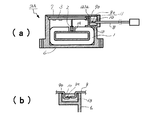
図1は、本発明の電子部品の第1実施例を示す図であり、図1(a)は断面図、図1(b)は斜視図である。
図2は、本発明の電子部品の第1実施例における組立方法を説明する組立図であり、
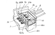
図3は、本発明の電子部品の第1実施例における要部を説明する部分拡大図であり、
図4は、本発明の電子部品の第1実施例における変形例を説明する断面図であり、
図5は、本発明の電子部品の第1実施例における他の変形例を説明する断面図であり、
図6は、本発明の電子部品の第1実施例における別の変形例を説明する断面図であり、
図7は、本発明の電子部品の第2実施例を示す断面図であり、
図8は、本発明の電子部品の第2実施例における変形例を説明する断面図である。
以下に詳述する本発明の電子部品の実施例は電流センサであり、図1(a),図1(b),図2,図3及び図4を用いて説明する。
図1(a)は、図2におけるA−A断面図である。
図3は、本発明の実施例の要部を一部破断した部分拡大図である。充填した樹脂10については、理解容易のために、断面のみを斑点で指示し、この樹脂10に没した部分がわかるように示している。
The preferred embodiments of the present invention will be described with reference to FIGS.
1, a first embodiment of an electronic component of the present invention Ri indicates to view der, 1 (a) is a cross-sectional view, FIG. 1 (b) Ru der perspective view.
Figure 2 is an assembly view illustrating an assembly method in the first embodiment of the electronic component of the present invention,
FIG. 3 is a partially enlarged view for explaining a main part in the first embodiment of the electronic component of the present invention.
FIG. 4 is a cross-sectional view illustrating a modification of the electronic component according to the first embodiment of the present invention.
FIG. 5 is a cross-sectional view for explaining another modification of the first embodiment of the electronic component of the present invention,
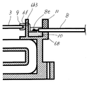
FIG. 6 is a cross-sectional view for explaining another modification of the first embodiment of the electronic component of the present invention,
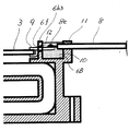
FIG. 7 is a cross-sectional view showing a second embodiment of the electronic component of the present invention,
FIG. 8 is a sectional view for explaining a modification of the second embodiment of the electronic component of the present invention.
An embodiment of the electronic component of the present invention described in detail below is a current sensor, and will be described with reference to FIGS. 1 (a), 1 (b), 2, 3, and 4. FIG.
Fig.1 (a) is AA sectional drawing in FIG.
FIG. 3 is a partially enlarged view in which a main part of the embodiment of the present invention is partially broken. For ease of understanding, the filled
この電流センサは、大電流の流れる電流路に負荷を与えずに正確な電流値を測定できるセンサであり、具体的には、図1(a)に示すように、磁気ギャップ1Aを有する略環状の磁気コア1の磁気ギャップ1間に、回路基板3に実装したホール素子2を配置し、磁気コア1の内部4に、被検出体である導線(図示せず)を貫通させ、この導線を流れる電流をホール素子2で検出する方式の電流センサ50である。
This current sensor is a sensor capable of measuring an accurate current value without applying a load to a current path through which a large current flows. Specifically, as shown in FIG. 1A, the current sensor has a substantially annular shape having a magnetic gap 1A. The
この電流センサ50の第1実施例について説明する。
電流センサ50は、回路が形成されて実装部品やホール素子2を実装した回路基板3と磁気コア1とを収納する、天面(図1(a)の上側)及び正面(図1(a)の手前側)が開放した略箱状の収納ケース6と、この収納ケース6にその開放面を覆うように装着される略L字状の蓋部7とを備えている。
収納ケース6及び蓋部7は、PBT(ポリブチレンテレフタレート)等の樹脂で形成することができる。
収納ケース6の対向する側面6s1,6s3の下方側には、この電流センサを図示しない外部機器にねじ等で装着するための装着部6a,6bが設けられている。
一方、右側面6s3の上方側には、外部との電気的入出力を行うリード線の引き出し部6Cが突出して形成されており、この引き出し部6Cから、先端がコネクタ8dに接続された3本のリード線8が引き出されている。
A first embodiment of the current sensor 50 will be described.
Current sensor 50 houses a
The
Mounting
On the other hand, on the upper side of the right side surface 6s3, there are formed lead wire lead portions 6C for electrical input / output with the outside, from which three lead wires connected to the connector 8d are connected.
収納ケース6の内部には、背面6s4から略矩形で環状の磁気コアガイド6Aが図1(a)の手前側に突出するように形成されている。そして、この磁気コアガイド6Aの外側には、磁気コア1が磁気ギャップ1Aを上側に向けて挿着されている。この磁気コア1は、パーマロイの薄板を所定形状に打ち抜いたものを積層して形成される。
磁気コアガイド6Aの内面の形状にほぼ対応するように、蓋部7には開口部7aが設けられている。この開口部7aと磁気コアガイド6Aとで形成された空洞部4中に被検出体である電線等が挿通される。
Inside the
The
収納ケース6の内部の上方には、収納ケース6の左側面6s1の内面に凹部として形成された基板保持部6d等の保持手段により、回路基板3が保持されている。図1(a)において、基板保持部6d以外の保持手段は省略されている。
この回路基板3の保持位置は、実装されたホール素子2が磁気ギャップ1A内に配置されるように設定されている。
Above the inside of the
The holding position of the
回路基板3の一方の端部3a近傍の両面には3対のランド3bが設けられており、それぞれにクリップリード9がはんだ付けにより接続されている(図2も参照)。
クリップリード9は、銅―ニッケル合金,鉄−ニッケル合金あるいは真鍮等の金属により形成され、一方の先端に回路基板3と強嵌合が可能なように二股に分かれた挟持部9aを有しており、その挟持部9aに回路基板3を挟持させることでランド3bとの接続が強固に確実に行えるものである。
また、クリップリード9の中間部分には、略コ字状に折り曲げられた屈曲部9bが形成され、挟持部9aの反対側端部は、リード線8のリードがはんだ付けにより接続されている。この部分を接続部8eと称する。
Three pairs of
The
Further, a bent portion 9b bent in a substantially U-shape is formed at the intermediate portion of the
収納ケース6の内部の、側面6s3側の上方には、背面6s4の一部を含んで壁部6b1〜6b4と底部6b5が形成されており、これらの壁部6b1〜6b4と底部6b5とで囲まれた空間として樹脂充填部6Bが形成される。
この樹脂充填部6Bにおける回路基板3側の壁部6b3の上端部6b3aに、クリップリード9の屈曲部9bの内面が係合し、クリップリード9は、この壁部6b3を乗り越えて跨ぐように配置される。
この状態で、クリップリード9とリード線8とが接続する接続部8eは、樹脂充填部6B内に配置される。
そして、この樹脂充填部6Bにエポキシ系の樹脂10が充填硬化しており、接続部8eとその近傍は、この樹脂10中に完全に没して被覆されると共に収納ケース6と一体化されている。
Wall portions 6b1 to 6b4 and a bottom portion 6b5 are formed above the side surface 6s3 side inside the
The inner surface of the bent portion 9b of the
In this state, the connecting
The
樹脂充填部6Bのリード線引き出し部6c側の壁部6b1には、リード線8のそれぞれをガイドする半円状の凹部6eが形成されており、リード線8が略強嵌合状態で係合する。
一方、樹脂充填部6Bの上方側には、リード線8を挟み込んで押さえるための略コ字状の押さえフレーム11が装着されている。
この押さえフレーム11は、壁部6b3,6b2に形成された切り欠き部6b3b,6b2bと強嵌合し、この嵌合状態で、壁部6b1の凹部6eと、これに対向するように押さえフレーム11に設けられた凹部11eとでリード線8は挟み込まれて保持される。
リード線8は弾力性のある絶縁被覆で覆われ屈曲自在な柔軟性を有するものである。そして、この弾力性のある絶縁被覆が挟持されているので、凹部6e,11eとの隙間はなく、樹脂充填時に樹脂10がここから漏れることはない。
A
On the other hand, a substantially
The
The
蓋部7は、図示しない係合手段により収納ケース6と係合し、これに装着されている。
The
次に、上述した電流センサ50の組立工程について図2を用いて詳述する。
組立は次の一連の工程により行われるが、これは一例であり、この一連の工程に限るものではない。
(工程1)ホール素子2が実装された回路基板3に屈曲部9bが形成されたクリップリード9をはんだ付けし、クリップリード9にリード線8をはんだ付けして3者を電気的に接続する。
(工程2)磁気ギャップ1Aを有する略環状の磁気コア1を収納ケース6の磁気コアガイド6Aに当図の矢印方向から挿着する。さらに、この磁気コア1と収納ケース6とを接着剤により固定してもよい。
(工程3)図の上方から回路基板3を回路基板保持部6d等の保持手段を介して装着する。その際、クリップリード9の屈曲部9bの内面を樹脂充填部6Bの壁部6b3に係合させ、リード線8の絶縁被覆部を壁部6b1の凹部6eに係合させる。
(工程4)図の上方から押さえフレーム11を樹脂充填部6Bに、切り欠き部6b3a,6b2aと強嵌合させるようにして装着する。これによりリード線8は、壁部6b1と押さえフレーム11とで隙間無く挟持される。
(工程5)樹脂充填部6Bに樹脂10を充填して硬化させる。これにより、クリップリード9とリード線8との接続部8e近傍が樹脂10内に完全に没して被覆され、収納ケース6と一体化する。充填に使用する樹脂としてエポキシ系が使用できるが、これに限るものではない。
(工程6)収納ケース6に蓋部7を装着する。
以上の工程により、電流センサ50が組み立てられる。
Next, the assembly process of the current sensor 50 will be described in detail with reference to FIG.
The assembly is performed by the following series of steps, but this is an example, and the present invention is not limited to this series of steps.
(Step 1) The
(Step 2) The substantially annular magnetic core 1 having the magnetic gap 1A is inserted into the
(Step 3) The
(Step 4) From the upper side of the figure, the
(Step 5) The
(Step 6) The
The current sensor 50 is assembled by the above process.
上述した実施例の回路部品は、略箱状の充填部6Bに樹脂10が充填されるので、他の部分に樹脂が流れて不良を発生させることがなく、所定の樹脂充填量で確実にリード線8の被覆が可能である。
また、クリップリード9を、充填部6Bの壁6b3を乗り越えるように屈曲部9bを設けて装着しているので、樹脂10が壁6b3側から漏れることがない。
また、屈曲部9bの屈曲形状を、回路基板3の図1(a)の上下方向保持位置に応じて最適な形状に形成することで、各部品の形状や内部のレイアウトを最適化することができる。
In the circuit component of the above-described embodiment, since the
Further, since the
In addition, by forming the bent shape of the bent portion 9b in an optimal shape according to the vertical holding position of the
特に、回路部品が電流センサである場合、磁気コア1が回路基板3に対して大きいのが一般的であるから、図1(a)に示したように、磁気ギャップ1Aを上方に向けて磁気コア1を配置し、その上方に回路基板3と充填部6Bとを並列配置する構成が最も小型化が可能で好ましい形態である。
この形態で、クリップリード9の、上述の実施例で略コ字状に屈曲させた屈曲部9bを、L字状に形成したクリップリード90として充填部6Bの壁6b3に係合させた電流センサ50Aとしてもよい。これを図4(a)に示す。
この場合は、回路基板3と磁気コア1との間隔を広くできるので、基板に搭載する部品の高さが高い場合に好適である。また、搭載する部品の高さが低い場合には、より小型化が可能な屈曲部9bをコ字状にする形態が好ましい。
In particular, when the circuit component is a current sensor, the magnetic core 1 is generally larger than the
In this configuration, the current sensor in which the bent portion 9b of the
In this case, since the space | interval of the
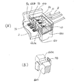
また、壁6b3の上端部6b3aに、クリップリード9の屈曲部9bの幅と厚さに合わせて凹部6b3cを形成し、その凹部6b3cに屈曲部9bを嵌合させるようにしてもよい。図5(A)はその斜視図であり、図5(B)は、屈曲部9bを部分的に切断して凹部6b3cをより明らかにした部分拡大斜視図である。
これにより、クリップリード9の位置が精度よく簡単に決まり、組み立てが容易になると共に位置のばらつきが無くなり、電子部品の品質が向上する。
Alternatively, a recess 6b3c may be formed in the upper end 6b3a of the wall 6b3 in accordance with the width and thickness of the bent portion 9b of the
As a result, the position of the
次に、電流センサの第2実施例について説明する。
この第2実施例は、第1実施例においてクリップリード9が壁部6b3の上端部6b3aを乗り越えて跨ぐように配置したのに対して、クリップリード9が壁部6b3に設けた貫通孔を挿通するように構成したものである。
この詳細を図7,図8を用いて説明する。ただし、第1実施例と同じ部分については、重複するので説明を省略する。
The following describes a second embodiment of a current sensor.
In the second embodiment, the
The details will be described with reference to FIGS. However, since the same parts as those in the first embodiment are duplicated, description thereof is omitted.
図7において、樹脂充填部6Bの壁部6b3には貫通孔6fが形成され、この貫通孔6fにクリップリード9が挿通されている。
貫通孔6fを挿通したクリップリード9は、充填部6B内でその底面に向かって折れ曲がり、リード線8と接続部8eで接続されている。
充填部6Bには、接続部8eとその近傍を完全に没して被覆するものの貫通孔6fには達しない量の樹脂10が充填硬化される。
In FIG. 7, a through
The
The filling
また、この第2実施例の変形例を図8に示す。
図8に示すように、この変形例は、樹脂充填部6Bの壁部6b3に貫通孔6fが形成され、この貫通孔6fにクリップリード9が挿通されているところは第2実施例と同様であるが、充填部6B内で折れ曲がることなくリード線8と接続部8eで接続されているものである。
充填部6Bには、接続部8eとその近傍を完全に没して被覆するように樹脂10が充填硬化されている。
A modification of the second embodiment is shown in FIG.
As shown in FIG. 8, in this modification, a through
The filling
ところで、貫通孔6fは円形であり、クリップリード9の断面は通常矩形であるので、両者間には隙間が生じる。
そこで、樹脂充填時にこの隙間から樹脂10が洩れ出さないように、その充填前に隙間を封止剤12で封止してある。
この封止剤として粘度の比較的高いUV硬化型接着剤を用いることができる。その場合、UV硬化型接着剤を塗布し紫外線を所定量照射してこれを硬化させた後、樹脂10を充填部6Bに充填すればよい。
封止剤はこれに限定されるものではなく、その硬化システムもUV照射に限るものではない。もちろん、充填する樹脂10を用いてもよい。
Incidentally, the through-
Therefore, as this gap between either
As this sealant, a UV curable adhesive having a relatively high viscosity can be used. In that case, after applying a UV curable adhesive and irradiating a predetermined amount of ultraviolet rays to cure it, the
The sealant is not limited to this, and the curing system is not limited to UV irradiation. Of course, the filling
これにより、基板3の位置とリード線8の位置をほぼ同一平面上に配置することができ、その位置を充填部6の底部6b5に接近させることで、充填部6Bに充填する樹脂10の量を極めて少なくすることができると共に、充填部6Bの深さをより浅くすることができ、電子部品の更なる小型化が可能となる。
これは、隙間を封止剤12で封止する工程と、充填部6Bに樹脂10を充填する工程とを分離することで実現するものである。
Thereby, the position of the
This is realized by separating the step of sealing between gap with
さて、本発明の各実施例は、上述した構成に限定されるものではなく、本発明の要旨を逸脱しない範囲において例えば下記のような変形例としてもよいものである。 The embodiments of the present invention are not limited to the above-described configuration, and may be modified as follows, for example, without departing from the gist of the present invention.
リード線8の引き出しは、凹部6e,11eで挟持する形態でなくてもよい。
収納ケースの側面6s3の上端を充填する樹脂10の表面よりも高くなるように延長して形成し、それを乗り越えるようにリード線8を略コ字状に屈曲させて引き出してもよい。この場合は、フレーム11が不要となる〔図4(b)参照〕。
The
The upper end of the side surface 6s3 of the storage case may be formed so as to be higher than the surface of the
クリップリードの替わりにクリップ機能のない周知のリード端子を基板のランドに半田により接続して用いてもよい。 Instead of the clip lead, a well-known lead terminal having no clip function may be connected to the land of the substrate by soldering.
クリップリード9における屈曲部9bから基板3のランド3bに達するまでの部分は、壁6b3の面に沿った自由な形状にすることができる。
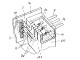
各実施例では水平に配置した基板を説明しているが、例えば垂直に配置した場合は、図6に示すように、方向変換部9dを設け、壁6b3に沿って折れ曲がる形状にしてもよい。
A portion of the
In each of the embodiments, the substrate disposed horizontally is described. However, when the substrate is disposed vertically, for example, as shown in FIG. 6, a
本発明は、上述した各実施例で説明した電流センサ50に限って適用可能なものではなく、電力センサや光センサ等の電子部品に適用可能である。
即ち、回路基板とこれを収納するケースと入出力のためのリード線とを備えた電子部品に適用可能なものである。
The present invention is not limited to the current sensor 50 described in each of the above-described embodiments, and can be applied to electronic components such as a power sensor and an optical sensor.
That is, the present invention can be applied to an electronic component having a circuit board, a case for storing the circuit board, and lead wires for input / output.
1 磁気コア
1A 磁気ギャップ
2 ホール素子
3 回路基板
3a 端部
3b ランド
4 空洞部
6 収納ケース
6A 磁気コアガイド
6B (樹脂)充填部
6s1〜6s4 側面
6a,6b 取り付け部
6c リード線引き出し部
6d 基板保持部
6b1〜6b4 (充填部6Bの)壁部
6b5 (充填部6Bの)底部
6b3a (壁部6b3の)上端部
6b3b,6b2b 切り欠き部
6e,11e 凹部
6f 貫通孔
7 蓋部
7a 開口部
8 リード線
8d コネクタ
8e 接続部
9 クリップリード
9a 挟持部
9b 屈曲部
9d 方向変換部
10 樹脂
11 押さえフレーム
12 封止剤(UV接着剤)
50,50A 電子部品(電流センサ)
DESCRIPTION OF SYMBOLS 1 Magnetic core 1A
6
7
50, 50A electronic components (current sensors)
Claims (2)
前記回路基板と前記リード端子とをケース内に収納すると共に、前記リード線の他端側を前記ケース外に引き出して成る電子部品であって、
前記ケースに、該ケース内に収納される前記リード端子の他端側と前記リード線の一端側との接続部を固定する樹脂を充填する樹脂充填部を形成し、
前記リード端子を、前記樹脂充填部の壁を跨いで配置すると共に、前記接続部及びその近傍を前記樹脂中に固定して成ることを特徴とする電子部品。 A circuit board, a lead terminal having one end connected to the circuit board, and a lead wire having one end connected to the other end of the lead terminal are sequentially arranged,
The circuit board and the lead terminal are housed in a case, and the other end side of the lead wire is drawn out of the case.
In the case, a resin filling portion is formed that fills a resin that fixes a connection portion between the other end side of the lead terminal accommodated in the case and one end side of the lead wire,
An electronic component comprising: the lead terminal disposed across the wall of the resin filling portion, and the connection portion and the vicinity thereof being fixed in the resin.
前記回路基板と前記リード端子とをケース内に収納すると共に、前記リード線の他端側を前記ケース外に引き出して成る電子部品であって、
前記ケースに、該ケース内に収納される前記リード端子の他端側と前記リード線の一端側との接続部を固定する樹脂を充填する樹脂充填部を形成し、
前記リード端子を、前記樹脂充填部の壁に設けた貫通孔に挿通させると共に、前記接続部及びその近傍を前記樹脂中に固定して成ることを特徴とする電子部品。 A circuit board, a lead terminal having one end connected to the circuit board, and a lead wire having one end connected to the other end of the lead terminal are sequentially arranged,
The circuit board and the lead terminal are housed in a case, and the other end side of the lead wire is drawn out of the case.
In the case, a resin filling portion is formed that fills a resin that fixes a connection portion between the other end side of the lead terminal accommodated in the case and one end side of the lead wire,
An electronic component, wherein the lead terminal is inserted into a through hole provided in a wall of the resin filling portion, and the connection portion and the vicinity thereof are fixed in the resin.
Priority Applications (2)
| Application Number | Priority Date | Filing Date | Title |
|---|---|---|---|
| JP2004112860A JP4207828B2 (en) | 2003-05-30 | 2004-04-07 | Electronic components |
| US10/853,125 US7002807B2 (en) | 2003-05-30 | 2004-05-26 | Electronic component |
Applications Claiming Priority (2)
| Application Number | Priority Date | Filing Date | Title |
|---|---|---|---|
| JP2003154299 | 2003-05-30 | ||
| JP2004112860A JP4207828B2 (en) | 2003-05-30 | 2004-04-07 | Electronic components |
Publications (2)
| Publication Number | Publication Date |
|---|---|
| JP2005019959A JP2005019959A (en) | 2005-01-20 |
| JP4207828B2 true JP4207828B2 (en) | 2009-01-14 |
Family
ID=33455576
Family Applications (1)
| Application Number | Title | Priority Date | Filing Date |
|---|---|---|---|
| JP2004112860A Expired - Lifetime JP4207828B2 (en) | 2003-05-30 | 2004-04-07 | Electronic components |
Country Status (2)
| Country | Link |
|---|---|
| US (1) | US7002807B2 (en) |
| JP (1) | JP4207828B2 (en) |
Families Citing this family (13)
| Publication number | Priority date | Publication date | Assignee | Title |
|---|---|---|---|---|
| US7573159B1 (en) | 2001-10-22 | 2009-08-11 | Apple Inc. | Power adapters for powering and/or charging peripheral devices |
| JP4877455B2 (en) * | 2005-03-28 | 2012-02-15 | ミツミ電機株式会社 | Secondary battery protection module and lead mounting method |
| JP4929659B2 (en) * | 2005-09-26 | 2012-05-09 | 株式会社ジェイテクト | Electronic control device |
| EP1780844B1 (en) * | 2005-11-01 | 2008-05-28 | BLACK & DECKER INC. | Remote ID resistor assembly for wiring harness |
| DE102007031727A1 (en) * | 2006-08-31 | 2008-03-20 | Zf Friedrichshafen Ag | Connecting element for connecting electrical conductors |
| JP5202172B2 (en) * | 2008-08-06 | 2013-06-05 | 富士通コンポーネント株式会社 | Memory card connector |
| US8815439B2 (en) | 2010-04-13 | 2014-08-26 | Samsung Sdi Co., Ltd. | Secondary battery pack |
| US20130081845A1 (en) * | 2011-09-30 | 2013-04-04 | Edward Siahaan | Housing for electronic components |
| JP5966154B2 (en) * | 2012-12-21 | 2016-08-10 | パナソニックIpマネジメント株式会社 | Electric blower and electric vacuum cleaner using the same |
| DE202015001193U1 (en) | 2014-02-18 | 2015-04-09 | Continental Automotive Gmbh | Electronic module |
| ITUB20159751A1 (en) * | 2015-12-30 | 2017-06-30 | Johnson Electric Asti S R L | Wiring with integrated connector, particularly for motor vehicles. |
| JP6974381B2 (en) * | 2019-03-25 | 2021-12-01 | 矢崎総業株式会社 | connector |
| JP6978711B1 (en) * | 2020-09-09 | 2021-12-08 | ダイキン工業株式会社 | Resin mold stator, outer rotor type motor, blower, air conditioner |
Family Cites Families (10)
| Publication number | Priority date | Publication date | Assignee | Title |
|---|---|---|---|---|
| US4335932A (en) * | 1980-02-29 | 1982-06-22 | Amp Incorporated | Elastomeric potting shell |
| JP2705368B2 (en) * | 1991-05-31 | 1998-01-28 | 株式会社デンソー | Electronic equipment |
| EP0516149B1 (en) * | 1991-05-31 | 1998-09-23 | Denso Corporation | Electronic device |
| US5646827A (en) * | 1991-05-31 | 1997-07-08 | Nippondenso Co., Ltd. | Electronic device having a plurality of circuit boards arranged therein |
| US5586388A (en) * | 1991-05-31 | 1996-12-24 | Nippondenso Co., Ltd. | Method for producing multi-board electronic device |
| JPH0555432A (en) | 1991-08-21 | 1993-03-05 | Mitsubishi Electric Corp | Connecting structure for clip lead to integrated circuit board |
| JPH0736071A (en) | 1993-07-15 | 1995-02-07 | Sony Corp | Waveform converting device |
| DE69508911T2 (en) * | 1994-11-28 | 1999-10-07 | Kabushiki Kaisha Toshiba, Kawasaki | Housing with electromagnetic shielding |
| JP2794558B2 (en) * | 1996-06-27 | 1998-09-10 | 日本航空電子工業株式会社 | Electronics |
| JP4234259B2 (en) * | 1999-05-14 | 2009-03-04 | 富士通テン株式会社 | Combination structure of electronic equipment |
-
2004
- 2004-04-07 JP JP2004112860A patent/JP4207828B2/en not_active Expired - Lifetime
- 2004-05-26 US US10/853,125 patent/US7002807B2/en not_active Expired - Lifetime
Also Published As
| Publication number | Publication date |
|---|---|
| US7002807B2 (en) | 2006-02-21 |
| US20040240187A1 (en) | 2004-12-02 |
| JP2005019959A (en) | 2005-01-20 |
Similar Documents
| Publication | Publication Date | Title |
|---|---|---|
| JP4207828B2 (en) | Electronic components | |
| JP4475160B2 (en) | Manufacturing method of electronic device | |
| JP5894735B2 (en) | Current sensor with laminated magnetic core | |
| JP4424412B2 (en) | Current sensor | |
| JP4301048B2 (en) | Pressure sensor and manufacturing method thereof | |
| JP5708424B2 (en) | Electronic circuit unit with external connection | |
| WO2010082654A1 (en) | Structure for assembling current detecting device | |
| CN108605420A (en) | Circuit structure and electrical connection box | |
| JP5026944B2 (en) | Current sensor | |
| JP4382546B2 (en) | Capacitor mounting structure | |
| JP2019036528A (en) | Electric connecting structure and manufacturing method thereof | |
| JP2010071724A (en) | Resin molded semiconductor sensor and method of manufacturing the same | |
| JP2018136278A (en) | Method for manufacturing physical quantity sensor device and physical quantity sensor device | |
| US10513231B2 (en) | Electronic component unit, wire harness, and connector fixing structure | |
| JP2006194683A (en) | Temperature sensor-integrated pressure sensor device | |
| JP5590699B2 (en) | Current detector assembly structure | |
| JP2009177055A (en) | Electronic component | |
| JP2012234894A (en) | Electronic circuit housing case and manufacturing method thereof | |
| JP2015159224A (en) | sensor structure | |
| WO2019102737A1 (en) | Flow rate meter | |
| JP2005322675A (en) | Surface-mounting coil component | |
| JP7490332B2 (en) | Reactor | |
| JP2005308526A (en) | Current sensor | |
| JP5720450B2 (en) | Pressure sensor and pressure sensor mounting structure | |
| JP6442430B2 (en) | Reactor |
Legal Events
| Date | Code | Title | Description |
|---|---|---|---|
| A621 | Written request for application examination |
Free format text: JAPANESE INTERMEDIATE CODE: A621 Effective date: 20060630 |
|
| A131 | Notification of reasons for refusal |
Free format text: JAPANESE INTERMEDIATE CODE: A131 Effective date: 20080627 |
|
| A521 | Request for written amendment filed |
Free format text: JAPANESE INTERMEDIATE CODE: A523 Effective date: 20080819 |
|
| TRDD | Decision of grant or rejection written | ||
| A01 | Written decision to grant a patent or to grant a registration (utility model) |
Free format text: JAPANESE INTERMEDIATE CODE: A01 Effective date: 20080930 |
|
| A01 | Written decision to grant a patent or to grant a registration (utility model) |
Free format text: JAPANESE INTERMEDIATE CODE: A01 |
|
| A61 | First payment of annual fees (during grant procedure) |
Free format text: JAPANESE INTERMEDIATE CODE: A61 Effective date: 20081013 |
|
| R151 | Written notification of patent or utility model registration |
Ref document number: 4207828 Country of ref document: JP Free format text: JAPANESE INTERMEDIATE CODE: R151 |
|
| FPAY | Renewal fee payment (event date is renewal date of database) |
Free format text: PAYMENT UNTIL: 20111031 Year of fee payment: 3 |
|
| FPAY | Renewal fee payment (event date is renewal date of database) |
Free format text: PAYMENT UNTIL: 20121031 Year of fee payment: 4 |
|
| FPAY | Renewal fee payment (event date is renewal date of database) |
Free format text: PAYMENT UNTIL: 20121031 Year of fee payment: 4 |
|
| S111 | Request for change of ownership or part of ownership |
Free format text: JAPANESE INTERMEDIATE CODE: R313111 |
|
| FPAY | Renewal fee payment (event date is renewal date of database) |
Free format text: PAYMENT UNTIL: 20121031 Year of fee payment: 4 |
|
| R350 | Written notification of registration of transfer |
Free format text: JAPANESE INTERMEDIATE CODE: R350 |
|
| FPAY | Renewal fee payment (event date is renewal date of database) |
Free format text: PAYMENT UNTIL: 20131031 Year of fee payment: 5 |
|
| EXPY | Cancellation because of completion of term |


