JP4207244B2 - Rolling bearing unit with rotational speed detection device and method of processing outer ring for rolling bearing unit with rotational speed detection device - Google Patents
Rolling bearing unit with rotational speed detection device and method of processing outer ring for rolling bearing unit with rotational speed detection device Download PDFInfo
- Publication number
- JP4207244B2 JP4207244B2 JP12772598A JP12772598A JP4207244B2 JP 4207244 B2 JP4207244 B2 JP 4207244B2 JP 12772598 A JP12772598 A JP 12772598A JP 12772598 A JP12772598 A JP 12772598A JP 4207244 B2 JP4207244 B2 JP 4207244B2
- Authority
- JP
- Japan
- Prior art keywords
- outer ring
- peripheral surface
- rotational speed
- rolling bearing
- bearing unit
- Prior art date
- Legal status (The legal status is an assumption and is not a legal conclusion. Google has not performed a legal analysis and makes no representation as to the accuracy of the status listed.)
- Expired - Fee Related
Links
Images


Description
【0001】
【発明の属する技術分野】
この発明は、自動車の車輪を懸架装置に対して回転自在に支持すると共に、この車輪の回転速度を検出する為に利用する回転速度検出装置付転がり軸受ユニット、並びにこの回転速度検出装置付転がり軸受ユニットを構成する外輪の改良に関する。
【0002】
【従来の技術】
自動車の車輪を懸架装置に対して回転自在に支持するのに、転がり軸受ユニットを使用する。又、アンチロックブレーキシステム(ABS)やトラクションコントロールシステム(TCS)を制御する為には、上記車輪の回転速度を検出する必要がある。この為、上記転がり軸受ユニットに回転速度検出装置を組み込んだ、回転速度検出装置付転がり軸受ユニットにより、上記車輪を懸架装置に対して回転自在に支持すると共に、この車輪の回転速度を検出する事が、近年広く行なわれる様になっている。
【0003】
この様な回転速度検出装置付転がり軸受ユニットは、外輪の内径側にハブを、複数の転動体を介して回転自在に支持している。これと共に、上記ハブの一部に固定した、円周方向に亙って特性を交互に且つ等間隔に変化させたエンコーダの回転速度を、上記外輪の一部に支持したセンサにより検出自在としている。又、このセンサを、上記外輪の軸方向中間部に、この外輪の直径方向に亙り形成した取付孔内に支持した状態で、このセンサの検出部を上記エンコーダの大径円筒部の外周面に対向させる事も、例えば特開昭63−59769号公報、特開平6−109027号公報、同8−270659号公報等、多くの刊行物に記載されている様に、従来から広く知られている。
【0004】
上述の様な回転速度検出装置付転がり軸受ユニットの使用時には、上記外輪を懸架装置に支持すると共に、上記ハブの一端部で上記外輪から外れた部分に車輪を固定し、この車輪を上記懸架装置に対して回転自在に支持する。車輪の回転に伴って上記エンコーダが回転すると、検出部をこのエンコーダに対向させたセンサの出力が変化する。このセンサの出力が変化する周波数は、上記車輪の回転速度に比例する。従って、このセンサの出力信号を上記車輪の回転速度を求める制御器に送れば、ABSやTCSを適切に制御できる。
【0005】
【発明が解決しようとする課題】
上述の様な各公報に記載された回転速度検出装置付転がり軸受ユニットの場合、外輪の耐久性確保と取付孔の加工容易性との両立を考慮していなかった。即ち、外輪の内周面に形成した複列の外輪軌道の表面及びこの表面近傍部分には、これら各外輪軌道の転がり疲れ寿命確保を目的として、硬度が例えばHv500以上である焼き入れ硬化層を形成する必要がある。又、上記外輪の一部内周面部分で複列の外輪軌道の間部分にも焼き入れ硬化層を形成し、この間部分を塑性変形しにくくする事も、例えば実用新案登録第2529597号公報等にも記載されている様に、従来から知られている。この様に、上記間部分を塑性変形しにくくすると、車輪が縁石にぶつかる等により、上記外輪に衝撃荷重が加わった場合でも、この外輪が塑性変形する事を防止して、この外輪を含む回転速度検出装置付転がり軸受ユニットの耐久性向上を図れる。尚、この様な場合でも、上記外輪の外周寄り部分には、焼き入れ硬化されていない生の部分を残して、上記外輪の靱性を確保し、この外輪に上記衝撃荷重に基づいて亀裂等の損傷が生じる事を防止する。
【0006】
ところが、上述の様に、外輪の一部内周面で複列の外輪軌道の間部分にも焼き入れ硬化層を形成した場合には、センサを支持固定する為に外輪に形成する取付孔の加工が難しくなる。
又、上記外輪の靱性を確保し、自動車の走行時に加わる可能性のある衝撃荷重に拘らず、この外輪に亀裂等の損傷が発生する事を防止すべく、この外輪の一部で上記間部分の外径寄り部分に、焼き入れ硬化されていない生の部分を残す為には、上記外輪の内周面に焼き入れ硬化層を、この外輪の外周面を冷媒により冷却しつつ形成する必要がある。この様な場合に、この外輪の内周面に冷媒が入り込み、焼き入れ硬化層にむらが生じる事を防止する必要があるが、従来は、この様な事を考慮する発明は知られていなかった。
本発明の回転速度検出装置付転がり軸受ユニットと回転速度検出装置付転がり軸受ユニット用外輪の加工方法は、この様な事情に鑑みて、焼き入れ硬化層により変形防止を図った外輪にも、センサを支持固定する為の取付孔を形成可能にすると共に、必要に応じて焼き入れ硬化層にむらが生じるのを防止すべく発明したものである。
【0007】
【課題を解決するための手段】
本発明の対象となる回転速度検出装置付転がり軸受ユニットは、従来から知られている回転速度検出装置付転がり軸受ユニットと同様に、外周面に複列の内輪軌道を有し、使用時に車輪と共に回転するハブと、内周面で上記複列の内輪軌道と対向する位置に複列の外輪軌道を有し、使用時に懸架装置に支持されて回転しない外輪と、上記各内輪軌道と上記各外輪軌道との間にそれぞれ複数個ずつ転動自在に設けた転動体と、上記ハブの中間部外周面で上記複列の内輪軌道の間部分に外嵌固定した、円周方向に亙って特性を交互に且つ等間隔に変化させたエンコーダと、検出部を有し、この検出部を上記エンコーダに対向させた状態で上記外輪の軸方向中間部に設けた取付孔内に支持され、上記エンコーダの特性の変化に対応して出力信号を変化させるセンサとを備える。そして、上記外輪の内周面で上記各外輪軌道部分及びこれら両外輪軌道の間部分に焼き入れ硬化層を形成している。
【0008】
特に、本発明の回転速度検出装置付転がり軸受ユニットのうち、請求項1に記載した回転速度検出装置付転がり軸受ユニットに於いては、上記焼き入れ硬化層は、上記取付孔を上記外輪の外周面側から直径方向に関して途中まで形成した状態で、この外輪を外周面側から冷媒により冷却しつつこの外輪の内周面を加熱して形成したものであり、上記取付孔は、上記焼き入れ硬化層を形成した後、上記外輪の内周面側にまで貫通させたものである 。
【0009】
そして、請求項2に記載した回転速度検出装置付転がり軸受ユニットを構成する外輪の加工方法は、取付孔を外輪の外周面側から直径方向に関して途中まで形成してから、上記外輪を外周面側から冷媒により冷却しつつこの外輪を内周面側から加熱して焼き入れ硬化層を形成した後、上記取付孔をこの外輪の内周面側にまで貫通させる。
【0010】
又、請求項3に記載した回転速度検出装置付転がり軸受ユニットに於いては、上記焼き入れ硬化層は、上記取付孔を形成した後、上記外輪を回転させながらこの外輪の外周面部分を、下方から上方に向けて吹き上げる冷媒により冷却しつつ、この外輪の内周面を加熱して形成したものである。
【0011】
そして、請求項4に記載した回転速度検出装置付転がり軸受ユニットを構成する外輪の加工方法は、外輪の軸方向中間部で複列の外輪軌道の間部分に取付孔を形成した後、この外輪を回転させながら、この外輪の外周面部分を下方から上方に向けて吹き上げる冷媒により冷却しつつ、この外輪の内周面を加熱して、焼き入れ硬化層を形成する。
【0012】
更に、請求項5に記載した回転速度検出装置付転がり軸受ユニットに於いては、上記焼き入れ硬化層は、上記取付孔を形成した後、この外輪の外周面部分を気体冷媒により冷却しつつ、この外輪の内周面を加熱して形成したものである。
そして、請求項6に記載した回転速度検出装置付転がり軸受ユニットを構成する外輪の加工方法は、外輪の軸方向中間部で複列の外輪軌道の間部分に取付孔を形成した後、この外輪の外周面部分を気体冷媒により冷却しつつ、この外輪の内周面を加熱して、焼き入れ硬化層を形成する。
【0013】
【作用】
上述の様に造る外輪を含んで構成する本発明の回転速度検出装置付転がり軸受ユニットにより、車輪を懸架装置に対して回転自在に支持すると共に、この車輪の回転速度を検出する際の作用は、従来から一般的に知られている回転速度検出装置付転がり軸受ユニットの場合と同様である。
【0014】
特に、本発明の回転速度検出装置付転がり軸受ユニットと回転速度検出装置付転がり軸受ユニット用外輪の加工方法によれば、焼き入れ硬化層により変形防止を図った外輪にも、センサを支持固定する為の取付孔を形成できる。この為、衝撃により変形しにくい外輪を備え、しかもこの外輪の軸方向中間部に形成した取付孔にセンサを支持固定した回転速度検出装置付転がり軸受ユニットを実現できる。
【0015】
【発明の実施の形態】
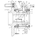
図1〜2は、本発明に関連する参考例の第1例を示している。本参考例の回転速度検出装置付転がり軸受ユニットを構成する転がり軸受ユニットは、ハブ本体1と内輪2とを組み合わせて成るハブ3と、外輪4と、複数個の転動体5、5とを備える。このうちのハブ本体1の外周面の外端部(外とは、自動車への組み付け状態で幅方向外寄りとなる側を言い、図1〜2の左側となる。反対に幅方向中央寄りとなる側を内と言い、図1〜2の右側となる。)には、車輪を支持する為のフランジ6を設けている。又、上記ハブ本体1の中間部外周面には内輪軌道7を形成している。尚、この内輪軌道7は、上記ハブ本体1の中間部外周面に直接形成する他、このハブ本体1の中間部外周面に外嵌した別体の内輪の外周面に形成する場合もある。
【0016】
又、上記ハブ本体1の内端部には、このハブ本体1の外周面から直径方向内方に凹入する段部8を、全周に亙りこのハブ本体1と同心に設けている。そして、この段部8に、外周面に別の内輪軌道7を形成した上記内輪2を、締り嵌めにより外嵌固定している。又、この様に外嵌固定した状態で上記内輪2の内端部は、上記ハブ本体1の内端面から軸方向内方に突出する。この内輪2の内端面は、車両への組み付け状態で、図示しない等速ジョイントの段差面に当接する。又、やはり車両への組み付け状態で、上記ハブ本体1の中心部に設けたスプライン孔9には、上記等速ジョイントに付属したスプライン軸を挿通する。そして、このスプライン軸の先端部で上記ハブ本体1の外端面よりも外方に突出した部分に設けた雄ねじ部に、やはり図示しないナットを螺合し、更に緊締する。このナットの緊締に基づいて、等速ジョイントの段差面が上記内輪2の内端面を強く押圧し、この内輪2が上記段部8から抜け出るのを防止する。又、上記段部8よりも大径に形成した上記ハブ本体1の中間部のうち、上記段部8側の端部には、このハブ本体1の中間部よりも少しだけ小径の嵌着部10を設けている。この嵌着部10の外径は、後述するエンコーダ11の自由状態での内径よりも僅かに大きくして、このエンコーダ11を締り嵌めにより外嵌固定自在としている。又、このエンコーダ11の外径は、上記嵌着部10に外嵌固定した状態で、ハブ本体1の中間部でこの嵌着部10よりも外寄り部分の外径以下としている。
【0017】
又、上記外輪4の内周面には、それぞれ上記各内輪軌道7、7と対向する、複列の外輪軌道12、12を形成している。そして、これら各内輪軌道7、7と各外輪軌道12、12との間にそれぞれ複数個ずつの転動体5、5を、それぞれ保持器13、13により保持した状態で転動自在に設ける事により、上記外輪4の内側に上記ハブ本体1及び内輪2を回転自在に支持している。尚、図示の例では、転動体5、5として玉を使用しているが、重量の嵩む自動車用の転がり軸受ユニットの場合には、これら転動体としてテーパころを使用する場合もある。又、上記外輪4の内端寄り部分の外周面には、この外輪4を懸架装置に取り付ける為の外向フランジ状の取付部14を設けている。又、上記外輪4の両端開口部と上記ハブ本体1の中間部外周面及び上記内輪2の内端部外周面との間の隙間は、それぞれシールリング15、15により塞いでいる。
【0018】
又、上記ハブ本体1の中間部外周面の一部で上記嵌着部10に、エンコーダ11を、このハブ本体1と同心に外嵌固定している。このエンコーダ11は、鋼板等の磁性金属板により、全体を円筒状に形成したもので、上記嵌着部10に締り嵌めで外嵌固定する事により、上記複列に設けた転動体5、5の列の間部分に配置している。又、このエンコーダ11の軸方向中間部には複数の透孔16、16を、円周方向に亙って等間隔に形成する事により、上記エンコーダ11の外周面の磁気特性を、円周方向に亙って交互に且つ等間隔に変化させている。
【0019】
一方、上記外輪4の軸方向中間部で上記エンコーダ11の直径方向外方位置には、取付孔17を、上記外輪4の内周面と外周面とを互いに連通させる状態で形成している。そして、この取付孔17内に、検出素子を合成樹脂中に包埋しているセンサ18を挿入固定し、このセンサ18の先端面(図1の下端面)に設けた検出部を、上記エンコーダ11の外周面に、微小隙間を介して対向させている。この様に取付孔17にセンサ18を挿入固定した状態で、このセンサ18は、上記エンコーダ11の回転速度を検出自在である。
【0020】
又、上記外輪4の外周面で上記取付孔17の外端開口の周囲部分には、この取付孔17の中心軸に対して直交する方向に存在する、平坦な取付面19を形成している。そして、この取付面19と上記取付孔17の内周面との連続部に、円錐凹面状の面取り部20と受面21とを、上記取付面19の側から順番に形成している。一方、上記センサ18の基端部(図1の上端部)には取付部22を固設し、この取付部22の端部に挿通した図示しないねじにより、この取付部22を上記外輪4に結合固定している。この状態で、上記センサ18の基端部に外嵌したOリング23を、この基端部の外周面と上記受面21の内周面との間で弾性的に圧縮する事により上記センサ18を装着した部分を密封し、上記取付孔17を通じて、雨水等の異物が上記外輪4内に侵入する事を防止している。
【0021】
更に、上記外輪4の内周面で前記各外輪軌道12、12部分及びこれら両外輪軌道12、12の間部分に、例えば硬度がHv500以上である焼き入れ硬化層24を形成している。この焼き入れ硬化層24の一部で上記各外輪軌道12、12に存在する部分は、前記各転動体5、5の転動面から繰り返し加えられる荷重に拘らず、上記各外輪軌道12、12部分の転がり疲れ寿命を確保する。これに対して、上記焼き入れ硬化層24の残部で両外輪軌道12、12の間部分に存在する中間部分は、この間部分を塑性変形しにくくする事により、車輪が縁石に乗り上げる等により上記各転動体5、5から加わる衝撃荷重に拘らず、上記外輪4のうちで上記間部分が塑性変形する事を防止する。尚、上記焼き入れ硬化層24は、外輪4の外周面部分を、冷却水、冷却油等の冷媒により冷却しつつ、この外輪4を内周面側から加熱して形成する(後述する本発明の実施の形態の第1例以下も同様)。この様に、外輪4の外周面部分を冷却しつつ、上記焼き入れ硬化層24を形成する理由は、この焼き入れ硬化層24の外径が過度に大きくなる事を防止して、上記外輪4の外周面側までもが硬くなる事を防止し、この外輪4の靱性を確保して、自動車の運行時に加わる可能性のある衝撃荷重に拘らず、この外輪4に割れ等の損傷が発生する事を防止する為である。合わせて、上記取付孔17の加工を行ないにくい上記焼き入れ硬化層24の厚さを薄くして、この取付孔17の加工の容易化を図っている。
【0022】
内周面に上述の様な焼き入れ硬化層24を形成した外輪4の軸方向中間部で、上記両外輪軌道12、12の間部分に上記取付孔17を、上記焼き入れ硬化層24を形成した後、超硬ドリル又はセラミックチップを備えたドリルにより形成している。上記間部分のうち、内周面寄りに存在する上記焼き入れ硬化層24部分は、例えば硬度がHv500以上と硬いが、超硬ドリル又はセラミックチップを備えたドリルによれば、十分に上記取付孔17を加工できる。従って、上記焼き入れ硬化層24により変形防止を図った外輪4にも、前記センサ18を支持固定する為の取付孔17を形成できる。尚、上記取付孔17を上記超硬ドリル又はセラミックチップを備えたドリルにより切削加工する際には、少なくとも切削部に切削油を注いで、切削部の冷却及び潤滑を行なう。この際に使用する潤滑油としては、非水溶性のものが好ましい。又、焼き入れ硬化層24部分に孔あけ加工をする際に発生する発熱は大きい為、上述の様に切削油を注ぐだけでなく、加工速度(上記ドリルの回転速度)を、鋼の生の部分に孔あけ加工をする場合に比べて遅くする事が好ましい。即ち、上記ドリルによる取付孔17の切削速度は、この取付孔17の内径(=ドリルの外径)が11〜13mm程度とした場合で、上記ドリルの外周面の速度で表して、20m/min 以下、更に好ましくは10m/min 以下にする。尚、焼き入れ硬化層でない、生の部分に上記取付孔17をあける場合の切削速度は、35〜41m/min 程度である。
【0023】
上述の様な本参考例の回転速度検出装置付転がり軸受ユニットの場合、ハブ本体1の外端部に設けたフランジ6に固定した車輪を、外輪4を支持した懸架装置に対し、回転自在に支持できる。又、車輪の回転に伴って上記ハブ本体1に外嵌固定したエンコーダ11が回転すると、上記センサ18の先端面に設けた検出部の近傍を、上記エンコーダ11の軸方向中間部に設けた透孔16、16と円周方向に隣り合う透孔16、16同士の間に存在する柱部とが交互に通過する。この結果、上記センサ18内を流れる磁束の量(密度)が変化し、このセンサ18の出力が変化する。この様にしてセンサ18の出力が変化する周波数は、車輪の回転速度に比例する。従って、センサ18の出力を図示しない制御器に送れば、ABSやTCSを適切に制御できる。
【0024】
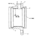
次に、図3〜5は、請求項1〜2に対応する、本発明の実施の形態の第1例を示している。本例の場合には、回転速度検出装置付転がり軸受ユニットを構成する外輪4の内周面の外輪軌道12、12及びこれら両外輪軌道12、12の間部分の焼き入れ硬化層24は、この間部分に取付孔17の元となる、有底の凹孔27を、この間部分の外周面側から形成した状態で形成したものである。又、上記取付孔17は、上記焼き入れ硬化層24を形成した後、上記外輪4の内周面側にまで貫通させたものである。
【0025】
即ち、図3に示す様に、上記取付孔17の元となる上記有底の凹孔27を、上記外輪4の外周面側から直径方向に関して途中まで形成してから、図4に示す様に、この外輪4の外周面部分を、冷却水、冷却油等の冷媒により冷却しつつ、この外輪4を内周面側から加熱して、図4に示す様に、中間部分の外径が小さくなった焼き入れ硬化層24を形成する。その後、超硬ドリル又はセラミックチップを備えたドリルにより上記凹孔27の底部を削り取って、図5に示す様に、上記外輪4の外周面側から内周面側にまで貫通した、上記取付孔17を形成する。上記凹孔27の底部を加工するのは、上述の様に超硬ドリル又はセラミックチップを備えたドリルの様な、硬い工具により行なう必要がある。但し、本例の場合には、加工代が少ないので、加工作業は容易である。又、同一の工具で生の部分と硬い部分との両方を加工する必要性も少ないので、工具の目づまり等を防止しつつ、能率の良い加工を行なえる。
【0026】
この様に、同一の工具で生の部分と硬い部分との両方を加工する事を極力避ける為に、上記焼き入れ硬化層24が上記凹孔27の底部にまで達する様に、これら焼き入れ硬化層24の厚さと凹孔27の深さとの関係を規制する事が好ましい。又、焼き入れ硬化層24を形成する為の熱処理時に於ける、上記凹孔27の底部近傍の変形を極力抑える為に、この底部の厚さ(凹孔27の底面から外輪4の内周面までの距離)は、1mm以上確保する事が好ましい。尚、本例の場合、上述の様に、上記焼き入れ硬化層24を形成する際に、上記外輪4の外周面を冷媒により冷却するが、この冷媒が上記取付孔17を通って、この外輪4の内周面に達する事はない。この為、上記外輪4の内周面で上記焼き入れ硬化層24を形成すべき部分に冷媒が付着する事により、この焼き入れ硬化層24に焼きむらが生じる事をなくせる。
【0027】
次に、図6は、やはり請求項1〜2に対応する、本発明の実施の形態の第2例を示している。本例の場合には、外輪4の軸方向中間部で複列の外輪軌道12、12(図1〜5)の間部分に形成する凹孔27aを、内周面寄り部分が深くなった形状としている。本例の場合には、この様な凹孔27aを形成した状態で、上記外輪4の外周面部分を、冷却水、冷却油等の冷媒により冷却しつつ、この外輪4の内周面の所定部位に焼き入れ硬化層を形成した後、この外輪4の内周面を図示しない受型に当接させた状態で、やはり図示しないパンチにより、上記凹孔27aの底部28を打ち抜いて、上記外輪4の外周面側から内周面側にまで貫通した取付孔を形成する。尚、取付孔の内端部で上記パンチにより打ち抜く部分の内径を、この取付孔内に挿入するセンサの先端部の外径に合わせて極力小さくする事により、打ち抜き加工の容易化を図る事も可能である。
【0028】
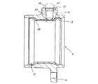
次に、図7〜10は、本発明に関連する参考例の第2例を示している。本参考例の場合には、回転速度検出装置付転がり軸受ユニットを構成する外輪4の内周面の外輪軌道12、12及びこれら両外輪軌道12、12の間部分の焼き入れ硬化層24は、この間部分に取付孔17を形成した後、この取付孔17の外端開口(外輪4の外周面側開口)を栓25により密閉した状態で、上記外輪4の外周面部分を、冷却水、冷却油等の冷媒により冷却しつつ形成したものである。
【0029】
即ち、上記外輪4に上記焼き入れ硬化層24及び取付孔17を形成するのに、先ず、図7に示す様に、上記外輪4に焼き入れ硬化層を形成しない、この外輪4が未だ生の状態で、この外輪4の軸方向中間部で上記複列の外輪軌道12、12の間部分に、上記取付孔17を形成する。その後、図8に示す様に、この取付孔17を、金属、セラミック等の耐熱材料製の栓25により密閉した状態で、上記外輪4の外周面で上記取付孔17の近傍を含む軸方向中間部分を冷媒により冷却しつつ、この外輪4の内側に配置した図示しない加熱コイルに通電する等により、この外輪4の内周面を加熱して、上記焼き入れ硬化層24を形成する。その後、上記栓25を取り外して、図9に示す様な外輪4とする。本例の場合、上記栓25の基部と上記取付孔17に形成した受面21との間にOリング26を設けて、これら栓25の外周面と取付孔17の内周面との間に、上記冷媒が入り込まない様にしている。
【0030】
尚、上記栓25自体を、ゴム等のエラストマー、或は合成樹脂等の弾性材により造れば、この栓25自体の弾性に基づき、上記取付孔17を密閉できる。この様な場合には、図10に示す様に、栓25の軸方向寸法を小さくしても良い。更には、栓を、金属又は合成樹脂により、上記取付孔17内には入り込まない(この取付孔17よりも大きな)板状に、又は一部が緩く入り込む形状に形成し、別途設けたばね或はバンド等によりこの板状等の栓を、上記外輪4の外周面で上記取付孔17部分に抑え付け、この取付孔17を塞いでも良い。この様に、栓25の軸方向寸法を小さくすれば、上記加熱コイルへの通電時に、上記取付孔17の内周面で上記栓25の一部が接触している部分が高温にならずに済む。従って、この栓25が耐熱材料製でなくても、上記外輪4の内周面の加熱時に、この栓25が損傷を受ける事はない。
【0031】
又、上記Oリング26は、上記栓25を上記取付孔17内に仮止め可能にしつつ、この栓25をこの取付孔17内に容易に着脱自在とする機能も有する。又、上記加熱の際、上記外輪4の両端開口部も、図示しない塞ぎ板等により塞ぎ、この外輪4の内側に上記冷媒が入り込まない様にする事もできる。この為、上記外輪4の内周面で上記焼き入れ硬化層24を形成すべき部分に冷媒が付着する事により、この焼き入れ硬化層24に焼きむらが生じる事をなくせる。この様な本例の場合には、上記焼き入れ硬化層24を形成する以前の、上記間部分が外周面から内周面まで総て生のままの状態で、この間部分に上記取付孔17を形成する為、この取付孔17の加工を容易に行なえる。
【0032】
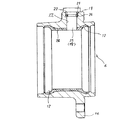
又、図11は、請求項3〜4に対応する、本発明の実施の形態の第3例を示している。本例の場合には、外輪4の軸方向中間部で複列の外輪軌道12、12の間部分に取付孔17を、この外輪4の内周面に焼き入れ硬化層を形成する以前に形成する。その後、この外輪4を回転させながら、この外輪4の外周面部分を、図11に矢印で示す様に、下方から上方に向けて吹き上げる液状の冷媒により冷却しつつ、上記外輪4の内周面を加熱して、上記焼き入れ硬化層を形成する。図11に矢印で示す、上記液状の冷媒の吹き上げ強さは、上記取付孔17が図11に示す様に下方に向いた状態でも、この冷媒がこの取付孔17を通じて上記外輪4の内側にまで入り込まない程度にする。即ち、上記冷媒がこの外輪4の外周面(下面)にまでは達するが、この外輪4の内周面にまでは達しない程度の強さとする。この様な本例の場合も、上記焼き入れ硬化層を形成する以前の、上記間部分が外周面から内周面まで総て生のままの状態で、この間部分に上記取付孔17を形成する為、この取付孔17の加工を容易に行なえる。
【0033】
更に、図示は省略するが、請求項5〜6に記載した様に、焼き入れ硬化層の形成作業を、外輪に取付孔を形成した後、この外輪の外周面部分を気体冷媒により冷却しつつ行なえば、形成後の取付孔を栓により塞いだり、或は冷媒の吹き付け強さを規制したりする事なく行なえる。この場合に使用する気体冷媒としては、液体窒素を蒸発させて得た低温窒素ガス等が使用可能である。この様な気体冷媒を使用する場合には、上記外輪を回転させる必要はないが、回転させない場合には、気体冷媒をこの外輪の外周面にまんべんなく吹き付けられる様に、外輪の周囲に複数の吹き付けノズルを配置する。
【0034】
尚、図示の例は、駆動輪(FR車及びRR車の後輪、FF車の前輪、4WD車の全輪)支持用の転がり軸受ユニットに本発明を適用した場合に就いて述べたが、本発明は、従動輪(FR車及びRR車の前輪、FF車の後輪)支持用の転がり軸受ユニットにも適用できる。又、本発明の特徴は、外輪の中間部に形成するセンサ支持固定用の取付孔の形成作業を容易に行なえる様にする点にある。回転速度検出装置の種類は、センサ及びエンコーダを含めて、特に限定するものではない。従って、回転速度検出装置は、図示の各例の様な磁気検知式のものに限らず、渦電流式、光電式等、他の構造のものを採用する事もできる。
【0035】
【発明の効果】
本発明は、以上に述べた通り構成され作用するので、回転速度検出装置付転がり軸受ユニットを構成する外輪の加工作業の容易化により、この回転速度検出装置付転がり軸受ユニットのコスト低減を図れる。
【図面の簡単な説明】
【図1】 本発明に関する参考例の第1例を示す断面図。
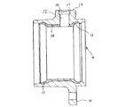
【図2】 外輪のみを取り出して示す断面図。
【図3】 本発明の実施の形態の第1例を示す、焼き入れ硬化層を形成する以前の外輪の断面図。
【図4】 同じく外輪に焼き入れ硬化層を形成した状態を示す断面図。
【図5】 焼き入れ硬化層及び取付孔を形成した外輪の断面図。
【図6】 本発明の実施の形態の第2例を示す、図4のA部に相当する断面図。
【図7】 本発明に関する参考例の第2例を示す、焼き入れ硬化層を形成する以前の外輪の断面図。
【図8】 同じく外輪に焼き入れ硬化層を形成する状態を示す断面図。
【図9】 焼き入れ硬化層を形成した外輪の断面図。
【図10】 栓の別例を示す、図8と同様の図。
【図11】 本発明の実施の形態の第3例を示す、外輪の断面図。
【符号の説明】
1 ハブ本体
2 内輪
3 ハブ
4 外輪
5 転動体
6 フランジ
7 内輪軌道
8 段部
9 スプライン孔
10 嵌着部
11 エンコーダ
12 外輪軌道
13 保持器
14 取付部
15 シールリング
16 透孔
17 取付孔
18 センサ
19 取付面
20 面取り部
21 受面
22 取付部
23 Oリング
24 焼き入れ硬化層
25 栓
26 Oリング
27、27a 凹孔
28 底部[0001]
BACKGROUND OF THE INVENTION
The present invention provides a rolling bearing unit with a rotational speed detection device and a rolling bearing with a rotational speed detection device, which are used for rotatably supporting a vehicle wheel relative to a suspension device and detecting the rotational speed of the wheel. It relates to the improvement of the outer ring constituting the unit.
[0002]
[Prior art]
A rolling bearing unit is used to rotatably support the wheels of the automobile with respect to the suspension system. Further, in order to control the anti-lock brake system (ABS) and the traction control system (TCS), it is necessary to detect the rotational speed of the wheel. For this reason, the rolling bearing unit with a rotational speed detection device incorporating a rotational speed detection device in the rolling bearing unit supports the wheel rotatably with respect to the suspension device, and detects the rotational speed of the wheel. However, in recent years it has become widely practiced.
[0003]
In such a rolling bearing unit with a rotational speed detection device, a hub is rotatably supported via a plurality of rolling elements on the inner diameter side of the outer ring. At the same time, fixed in a part of the hub, in the circumferential directionCrawlingThe rotation speed of the encoder whose characteristics are alternately changed at equal intervals can be detected by a sensor supported on a part of the outer ring. Also, with this sensor supported in a mounting hole formed in the axial direction intermediate portion of the outer ring and extending in the diameter direction of the outer ring, the detection portion of the sensor is placed on the outer peripheral surface of the large-diameter cylindrical portion of the encoder. The facing is also widely known in the past, as described in many publications such as JP-A-63-59769, JP-A-6-109027, and JP-A-8-270659. .
[0004]
When the rolling bearing unit with a rotational speed detection device as described above is used, the outer ring is supported by the suspension device, and a wheel is fixed to a portion of the hub that is detached from the outer ring, and the wheel is fixed to the suspension device. It is supported so that it can rotate freely. When the encoder rotates with the rotation of the wheel, the output of the sensor having the detection unit opposed to the encoder changes. The frequency at which the output of this sensor changes is proportional to the rotational speed of the wheel. Therefore, if the output signal of this sensor is sent to the controller for determining the rotational speed of the wheel, ABS and TCS can be controlled appropriately.
[0005]
[Problems to be solved by the invention]
In the case of the rolling bearing unit with a rotational speed detection device described in each of the above-mentioned publications, the balance between ensuring the durability of the outer ring and the processability of the mounting hole has not been considered. That is, on the surface of the double row outer ring raceway formed on the inner peripheral surface of the outer ring and a portion in the vicinity of the surface, a hardened hardened layer having a hardness of, for example, Hv 500 or more is provided for the purpose of ensuring the rolling fatigue life of each outer ring raceway. Need to form. In addition, a hardened hardened layer is also formed in a portion between the outer ring raceways of the double row at a part of the inner peripheral surface portion of the outer ring, and it is difficult to plastically deform the portion between these, for example in Utility Model Registration No. 2529597 As is also described, it is conventionally known. In this way, if the intermediate portion is difficult to be plastically deformed, even if an impact load is applied to the outer ring due to the wheel hitting the curbstone, etc., the outer ring is prevented from being plastically deformed, and the rotation including the outer ring is prevented. The durability of the rolling bearing unit with speed detecting device can be improved. Even in such a case, the outer ring has a raw portion that is not quenched and hardened in the vicinity of the outer periphery to ensure the toughness of the outer ring, and the outer ring is cracked based on the impact load. Prevent damage.
[0006]
However, as described above, when a hardened hardened layer is also formed on the part of the inner ring between the outer ring raceways on a part of the inner ring surface, the mounting holes formed in the outer ring to support and fix the sensor are processed. Becomes difficult.
In addition, in order to ensure the toughness of the outer ring and to prevent the outer ring from being damaged such as cracks regardless of the impact load that may be applied when the vehicle is running, a part of the outer ring may In order to leave a raw part that has not been hardened by quenching at a portion near the outer diameter of the outer ring, it is necessary to form a hardened hardened layer on the inner peripheral surface of the outer ring while cooling the outer peripheral surface of the outer ring with a refrigerant. is there. In such a case, it is necessary to prevent the refrigerant from entering the inner peripheral surface of the outer ring and causing unevenness in the hardened and hardened layer. However, conventionally, no invention that takes this into account has been known. It was.
In view of such circumstances, the rolling bearing unit with a rotational speed detection device and the method for processing the outer ring for a rolling bearing unit with a rotational speed detection device according to the present invention include a sensor for an outer ring that is prevented from being deformed by a hardened hardened layer. It was invented to make it possible to form a mounting hole for supporting and fixing the film and to prevent unevenness in the hardened and hardened layer if necessary.
[0007]
[Means for Solving the Problems]
The rolling bearing unit with a rotational speed detection device, which is the subject of the present invention, has a double-row inner ring raceway on the outer peripheral surface, like the conventionally known rolling bearing unit with a rotational speed detection device. A rotating hub; an outer ring having a double-row outer ring raceway at a position facing the double-row inner ring raceway on an inner peripheral surface; and being supported by a suspension device during use; the inner ring raceway and the outer ring A plurality of rolling elements provided between the raceway and a plurality of rolling elements, and an outer peripheral surface of the intermediate portion of the hub, and fitted and fixed to a portion between the double row inner ring raceways in a circumferential direction.CrawlingAn encoder having characteristics alternately changed at equal intervals and a detector, and supported in a mounting hole provided in an axially intermediate portion of the outer ring in a state where the detector is opposed to the encoder, A sensor that changes the output signal in response to a change in the characteristics of the encoder. A hardened hardened layer is formed on the inner peripheral surface of the outer ring at each outer ring raceway portion and between the outer ring raceways.
[0008]
In particular, in the rolling bearing unit with a rotational speed detection device of the present invention, in the rolling bearing unit with a rotational speed detection device according to
[0009]
And in claim 2The processing method of the outer ring constituting the rolling bearing unit with the rotational speed detection device described is that the mounting hole is formed from the outer peripheral surface side of the outer ring to the middle in the diametrical direction, and then the outer ring is cooled by the refrigerant from the outer peripheral surface side. After this outer ring is heated from the inner peripheral surface side to form a hardened hardened layer, the mounting hole is penetrated to the inner peripheral surface side of the outer ring.
[0010]
In the rolling bearing unit with a rotational speed detection device according to
[0011]
And claim 4The processing method of the outer ring that constitutes the rolling bearing unit with a rotational speed detection device described in 1), after forming the mounting hole in the portion between the double row outer ring raceways in the axial direction intermediate part of the outer ring, while rotating the outer ring, While cooling the outer peripheral surface portion of the outer ring with the refrigerant blown upward from below, the inner peripheral surface of the outer ring is heated to form a hardened hardening layer.
[0012]
Furthermore,Claim 5In the rolling bearing unit with a rotational speed detection device described in 1), after the hardened hardened layer has formed the mounting hole, the outer peripheral surface portion of the outer ring is cooled with a gaseous refrigerant while the inner periphery of the outer ring is cooled. The surface is formed by heating.
AndClaim 6The processing method of the outer ring constituting the rolling bearing unit with the rotational speed detection device described in 1) is to form the mounting hole in the portion between the double row outer ring raceways in the axial direction intermediate portion of the outer ring, and then to change the outer peripheral surface portion of the outer ring. While cooling with a gaseous refrigerant, the inner peripheral surface of the outer ring is heated to form a hardened and hardened layer.
[0013]
[Action]
The rolling bearing unit with a rotational speed detection device of the present invention configured to include the outer ring constructed as described above supports the wheel rotatably with respect to the suspension device, and the operation when detecting the rotational speed of the wheel is as follows. This is the same as the case of a rolling bearing unit with a rotational speed detection device that has been generally known.
[0014]
Particularly, according to the rolling bearing unit with a rotational speed detection device and the processing method of the outer ring for the rolling bearing unit with a rotational speed detection device of the present invention, the sensor is supported and fixed to the outer ring which is prevented from being deformed by a hardened hardened layer. Mounting holes can be formed. For this reason, it is possible to realize a rolling bearing unit with a rotational speed detection device that includes an outer ring that is not easily deformed by an impact, and that supports and fixes a sensor in a mounting hole formed in an axially intermediate portion of the outer ring.
[0015]
DETAILED DESCRIPTION OF THE INVENTION
1 and 2 show reference examples related to the present invention.First exampleIs shown. The rolling bearing unit constituting the rolling bearing unit with a rotational speed detecting device of this reference example includes a
[0016]
Further, a
[0017]
Further, double-row
[0018]
An
[0019]
On the other hand, a mounting
[0020]
A flat mounting
[0021]
Further, a hardened
[0022]
At the intermediate portion in the axial direction of the
[0023]
As mentioned aboveThis reference exampleIn the case of the rolling bearing unit with the rotational speed detection device, the wheel fixed to the flange 6 provided at the outer end of the
[0024]
Next, FIGS. 3 to 5 show a first example of an embodiment of the present invention corresponding to
[0025]
That is, as shown in FIG. 3, after forming the bottomed
[0026]
In this way, in order to avoid processing the raw part and the hard part with the same tool as much as possible, the quench hardening
[0027]
Next, FIG.Claims 1-2Corresponding to the embodiment of the present inventionSecond exampleIs shown. In the case of this example, the
[0028]
Next, FIGS.Second example of reference example related to the present inventionIs shown.This reference exampleIn this case, the
[0029]
That is, in order to form the quenched and hardened
[0030]
still,If the
[0031]
or,The O-
[0032]
Also, FIG.Claims 3-4Corresponding to the embodiment of the present inventionThird exampleIs shown. In the case of this example, the mounting
[0033]
Furthermore, although illustration is omitted,Claims 5-6As described above, if the hardening hardened layer is formed by forming a mounting hole in the outer ring and then cooling the outer peripheral surface portion of the outer ring with a gas refrigerant, the formed mounting hole is closed with a plug. Or it can be done without regulating the spraying strength of the refrigerant. As the gaseous refrigerant used in this case, low-temperature nitrogen gas obtained by evaporating liquid nitrogen or the like can be used. When such a gas refrigerant is used, it is not necessary to rotate the outer ring. However, if the outer ring is not rotated, a plurality of sprays can be applied around the outer ring so that the gas refrigerant can be sprayed evenly on the outer peripheral surface of the outer ring. Place the nozzle.
[0034]
In the illustrated example, the present invention is applied to a rolling bearing unit for supporting driving wheels (rear wheels of FR and RR vehicles, front wheels of FF vehicles, all wheels of 4WD vehicles). The present invention can also be applied to a rolling bearing unit for supporting driven wheels (front wheels of FR vehicles and RR vehicles, rear wheels of FF vehicles). Further, the present invention is characterized in that it is possible to easily perform a work for forming a mounting hole for fixing and supporting a sensor formed in an intermediate portion of the outer ring. There are no particular limitations on the type of rotational speed detection device, including sensors and encoders. Therefore, the rotational speed detection device is not limited to the magnetic detection type as shown in the illustrated examples, but may be of another structure such as an eddy current type or a photoelectric type.
[0035]
【The invention's effect】
Since the present invention is configured and operates as described above, the cost of the rolling bearing unit with a rotational speed detecting device can be reduced by facilitating the processing work of the outer ring constituting the rolling bearing unit with the rotational speed detecting device.
[Brief description of the drawings]
FIG. 1 is a reference example of the present invention.First exampleFIG.
FIG. 2 is a sectional view showing only an outer ring.
FIG. 3 shows an embodiment of the present invention.First exampleSectional drawing of the outer ring | wheel before forming a hardening hardening layer which shows these.
FIG. 4 is a cross-sectional view showing a state where a hardened hardening layer is similarly formed on the outer ring.
FIG. 5 is a cross-sectional view of an outer ring in which a hardened hardening layer and a mounting hole are formed.
FIG. 6 shows an embodiment of the present invention.Second exampleSectional drawing equivalent to the A section of FIG.
FIG. 7Second example of reference exampleSectional drawing of the outer ring | wheel before forming a hardening hardening layer which shows these.
FIG. 8 is a cross-sectional view showing a state where a hardened hardening layer is similarly formed on the outer ring.
FIG. 9 is a cross-sectional view of an outer ring on which a hardened hardening layer is formed.
FIG. 10 is a view similar to FIG. 8, showing another example of the stopper.
FIG. 11 shows an embodiment of the present invention.Third exampleSectional drawing of an outer ring | wheel which shows.
[Explanation of symbols]
1 Hub body
2 inner ring
3 Hub
4 outer ring
5 Rolling elements
6 Flange
7 Inner ring raceway
8 steps
9 Spline hole
10 fitting part
11 Encoder
12 Outer ring raceway
13 Cage
14 Mounting part
15 Seal ring
16 Through hole
17 Mounting hole
18 sensors
19 Mounting surface
20 Chamfer
21 Reception surface
22 Mounting part
23 O-ring
24 Hardened and hardened layer
25 stoppers
26 O-ring
27, 27a concave hole
28 Bottom
Claims (6)
Priority Applications (8)
| Application Number | Priority Date | Filing Date | Title |
|---|---|---|---|
| JP12772598A JP4207244B2 (en) | 1998-03-09 | 1998-05-11 | Rolling bearing unit with rotational speed detection device and method of processing outer ring for rolling bearing unit with rotational speed detection device |
| US09/262,022 US6287009B1 (en) | 1998-03-06 | 1999-03-04 | Rolling bearing unit with rotation speed detection instrument for use in cars and method for working outer race for use in this bearing unit |
| EP19990301703 EP0940682B1 (en) | 1998-03-06 | 1999-03-08 | Roller bearing unit with rotation speed detection instrument for use in cars |
| DE69941798T DE69941798D1 (en) | 1998-03-06 | 1999-03-08 | Method for forming a roller bearing unit with speed measuring instrument |
| DE1999613404 DE69913404T2 (en) | 1998-03-06 | 1999-03-08 | Roller bearing unit with speed measuring instrument for use in motor vehicles |
| EP20030004545 EP1324047B1 (en) | 1998-03-06 | 1999-03-08 | Method for forming a rolling bearing unit with a rotation speed detection instrument |
| US09/901,123 US6568855B2 (en) | 1998-03-06 | 2001-07-10 | Rolling bearing unit with rotation speed detection instrument for use in cars and method for working outer race for use in this bearing unit |
| US10/395,289 US20030185476A1 (en) | 1998-03-06 | 2003-03-25 | Rolling bearing unit with rotation speed detection instrument for use in cars and method for working outer race for use in this bearing unit |
Applications Claiming Priority (3)
| Application Number | Priority Date | Filing Date | Title |
|---|---|---|---|
| JP10-57102 | 1998-03-09 | ||
| JP5710298 | 1998-03-09 | ||
| JP12772598A JP4207244B2 (en) | 1998-03-09 | 1998-05-11 | Rolling bearing unit with rotational speed detection device and method of processing outer ring for rolling bearing unit with rotational speed detection device |
Publications (2)
| Publication Number | Publication Date |
|---|---|
| JPH11325058A JPH11325058A (en) | 1999-11-26 |
| JP4207244B2 true JP4207244B2 (en) | 2009-01-14 |
Family
ID=26398126
Family Applications (1)
| Application Number | Title | Priority Date | Filing Date |
|---|---|---|---|
| JP12772598A Expired - Fee Related JP4207244B2 (en) | 1998-03-06 | 1998-05-11 | Rolling bearing unit with rotational speed detection device and method of processing outer ring for rolling bearing unit with rotational speed detection device |
Country Status (1)
| Country | Link |
|---|---|
| JP (1) | JP4207244B2 (en) |
Families Citing this family (1)
| Publication number | Priority date | Publication date | Assignee | Title |
|---|---|---|---|---|
| JP4517991B2 (en) * | 2005-09-14 | 2010-08-04 | 株式会社ジェイテクト | Guide roller device and guide roller device manufacturing method |
-
1998
- 1998-05-11 JP JP12772598A patent/JP4207244B2/en not_active Expired - Fee Related
Also Published As
| Publication number | Publication date |
|---|---|
| JPH11325058A (en) | 1999-11-26 |
Similar Documents
| Publication | Publication Date | Title |
|---|---|---|
| EP1324047B1 (en) | Method for forming a rolling bearing unit with a rotation speed detection instrument | |
| JP4771357B2 (en) | Method for assembling wheel bearing device with rotational speed detection device | |
| EP1705089B1 (en) | A wheel bearing apparatus incorporated with a wheel speed detecting apparatus | |
| EP2085249B1 (en) | Hub unit | |
| US7931409B2 (en) | Wheel bearing apparatus | |
| EP3444491B2 (en) | Hub unit bearing | |
| US10598226B2 (en) | Bearing device for vehicle wheel | |
| US7737682B2 (en) | Wheel speed detecting apparatus and a wheel bearing apparatus incorporated with a wheel speed detecting apparatus | |
| JP2006329320A (en) | Wheel bearing device | |
| JP2014013073A (en) | Wheel bearing device | |
| JP5057553B2 (en) | Wheel bearing device | |
| JP4207244B2 (en) | Rolling bearing unit with rotational speed detection device and method of processing outer ring for rolling bearing unit with rotational speed detection device | |
| US8657502B2 (en) | Inner ring of wheel bearing device, manufacturing method therefor, and wheel bearing device | |
| JP2004345543A (en) | Bearing system for wheel | |
| JPH11248726A (en) | Rolling bearing unit with rotation speed detecting device | |
| WO2015037677A1 (en) | Bearing device for wheel and method for manufacturing said device | |
| JP5317168B2 (en) | Wheel bearing device | |
| JP3869204B2 (en) | Axle bearing device | |
| JP2009058077A (en) | Wheel bearing unit | |
| US20190105946A1 (en) | Hub unit bearing | |
| JP4483852B2 (en) | Rotating support device for wheel and assembling method thereof | |
| JP5057558B2 (en) | Wheel bearing device | |
| JP2010043670A (en) | Wheel-bearing device | |
| JP2005119383A (en) | Bearing device for wheel | |
| JP2003130063A (en) | Bearing unit with built-in rotary encoder |
Legal Events
| Date | Code | Title | Description |
|---|---|---|---|
| A521 | Written amendment |
Free format text: JAPANESE INTERMEDIATE CODE: A523 Effective date: 20050311 |
|
| A621 | Written request for application examination |
Free format text: JAPANESE INTERMEDIATE CODE: A621 Effective date: 20050311 |
|
| A131 | Notification of reasons for refusal |
Free format text: JAPANESE INTERMEDIATE CODE: A131 Effective date: 20071113 |
|
| A521 | Written amendment |
Free format text: JAPANESE INTERMEDIATE CODE: A523 Effective date: 20080111 |
|
| A131 | Notification of reasons for refusal |
Free format text: JAPANESE INTERMEDIATE CODE: A131 Effective date: 20080527 |
|
| A521 | Written amendment |
Free format text: JAPANESE INTERMEDIATE CODE: A523 Effective date: 20080718 |
|
| TRDD | Decision of grant or rejection written | ||
| A01 | Written decision to grant a patent or to grant a registration (utility model) |
Free format text: JAPANESE INTERMEDIATE CODE: A01 Effective date: 20080930 |
|
| A01 | Written decision to grant a patent or to grant a registration (utility model) |
Free format text: JAPANESE INTERMEDIATE CODE: A01 |
|
| A61 | First payment of annual fees (during grant procedure) |
Free format text: JAPANESE INTERMEDIATE CODE: A61 Effective date: 20081013 |
|
| R150 | Certificate of patent or registration of utility model |
Free format text: JAPANESE INTERMEDIATE CODE: R150 |
|
| FPAY | Renewal fee payment (event date is renewal date of database) |
Free format text: PAYMENT UNTIL: 20111031 Year of fee payment: 3 |
|
| FPAY | Renewal fee payment (event date is renewal date of database) |
Free format text: PAYMENT UNTIL: 20111031 Year of fee payment: 3 |
|
| FPAY | Renewal fee payment (event date is renewal date of database) |
Free format text: PAYMENT UNTIL: 20121031 Year of fee payment: 4 |
|
| FPAY | Renewal fee payment (event date is renewal date of database) |
Free format text: PAYMENT UNTIL: 20121031 Year of fee payment: 4 |
|
| FPAY | Renewal fee payment (event date is renewal date of database) |
Free format text: PAYMENT UNTIL: 20131031 Year of fee payment: 5 |
|
| LAPS | Cancellation because of no payment of annual fees |