JP5317168B2 - Wheel bearing device - Google Patents
Wheel bearing device Download PDFInfo
- Publication number
- JP5317168B2 JP5317168B2 JP2008145276A JP2008145276A JP5317168B2 JP 5317168 B2 JP5317168 B2 JP 5317168B2 JP 2008145276 A JP2008145276 A JP 2008145276A JP 2008145276 A JP2008145276 A JP 2008145276A JP 5317168 B2 JP5317168 B2 JP 5317168B2
- Authority
- JP
- Japan
- Prior art keywords
- mounting flange
- hole
- vehicle body
- wheel
- knuckle
- Prior art date
- Legal status (The legal status is an assumption and is not a legal conclusion. Google has not performed a legal analysis and makes no representation as to the accuracy of the status listed.)
- Expired - Fee Related
Links
Images


Classifications
-
- F—MECHANICAL ENGINEERING; LIGHTING; HEATING; WEAPONS; BLASTING
- F16—ENGINEERING ELEMENTS AND UNITS; GENERAL MEASURES FOR PRODUCING AND MAINTAINING EFFECTIVE FUNCTIONING OF MACHINES OR INSTALLATIONS; THERMAL INSULATION IN GENERAL
- F16C—SHAFTS; FLEXIBLE SHAFTS; ELEMENTS OR CRANKSHAFT MECHANISMS; ROTARY BODIES OTHER THAN GEARING ELEMENTS; BEARINGS
- F16C33/00—Parts of bearings; Special methods for making bearings or parts thereof
- F16C33/72—Sealings
- F16C33/723—Shaft end sealing means, e.g. cup-shaped caps or covers
-
- F—MECHANICAL ENGINEERING; LIGHTING; HEATING; WEAPONS; BLASTING
- F16—ENGINEERING ELEMENTS AND UNITS; GENERAL MEASURES FOR PRODUCING AND MAINTAINING EFFECTIVE FUNCTIONING OF MACHINES OR INSTALLATIONS; THERMAL INSULATION IN GENERAL
- F16C—SHAFTS; FLEXIBLE SHAFTS; ELEMENTS OR CRANKSHAFT MECHANISMS; ROTARY BODIES OTHER THAN GEARING ELEMENTS; BEARINGS
- F16C19/00—Bearings with rolling contact, for exclusively rotary movement
- F16C19/02—Bearings with rolling contact, for exclusively rotary movement with bearing balls essentially of the same size in one or more circular rows
- F16C19/14—Bearings with rolling contact, for exclusively rotary movement with bearing balls essentially of the same size in one or more circular rows for both radial and axial load
- F16C19/18—Bearings with rolling contact, for exclusively rotary movement with bearing balls essentially of the same size in one or more circular rows for both radial and axial load with two or more rows of balls
- F16C19/181—Bearings with rolling contact, for exclusively rotary movement with bearing balls essentially of the same size in one or more circular rows for both radial and axial load with two or more rows of balls with angular contact
- F16C19/183—Bearings with rolling contact, for exclusively rotary movement with bearing balls essentially of the same size in one or more circular rows for both radial and axial load with two or more rows of balls with angular contact with two rows at opposite angles
- F16C19/184—Bearings with rolling contact, for exclusively rotary movement with bearing balls essentially of the same size in one or more circular rows for both radial and axial load with two or more rows of balls with angular contact with two rows at opposite angles in O-arrangement
- F16C19/186—Bearings with rolling contact, for exclusively rotary movement with bearing balls essentially of the same size in one or more circular rows for both radial and axial load with two or more rows of balls with angular contact with two rows at opposite angles in O-arrangement with three raceways provided integrally on parts other than race rings, e.g. third generation hubs
-
- F—MECHANICAL ENGINEERING; LIGHTING; HEATING; WEAPONS; BLASTING
- F16—ENGINEERING ELEMENTS AND UNITS; GENERAL MEASURES FOR PRODUCING AND MAINTAINING EFFECTIVE FUNCTIONING OF MACHINES OR INSTALLATIONS; THERMAL INSULATION IN GENERAL
- F16C—SHAFTS; FLEXIBLE SHAFTS; ELEMENTS OR CRANKSHAFT MECHANISMS; ROTARY BODIES OTHER THAN GEARING ELEMENTS; BEARINGS
- F16C2326/00—Articles relating to transporting
- F16C2326/01—Parts of vehicles in general
- F16C2326/02—Wheel hubs or castors
Description
本発明は、自動車等の車輪を懸架装置に対して回転自在に支承する車輪用軸受装置、詳しくは、外方部材の外周にナックルと嵌合するためのパイロット部がなく、ナックルに突き合わせ状態で、車体取付フランジが接合された従動輪側の車輪用軸受装置に関するものである。 The present invention relates to a wheel bearing device for rotatably supporting a wheel of an automobile or the like with respect to a suspension device, and more specifically, there is no pilot portion for fitting with a knuckle on an outer periphery of an outer member, and the knuckles are in a butted state. The present invention relates to a wheel bearing device on the driven wheel side to which a vehicle body mounting flange is joined.
自動車等の車輪を懸架装置に対して回転自在に支承する車輪用軸受装置には駆動輪用のものと従動輪用のものとがあるが、低コスト化は言うまでもなく、燃費向上のための軽量・コンパクト化が進んでいる。その従来構造の一例として、図10に示すような従動輪側の車輪用軸受装置が知られている。 Wheel bearing devices that support the wheels of automobiles and the like so that they can rotate with respect to a suspension device are available for driving wheels and for driven wheels.・ Compact is progressing. As an example of the conventional structure, a wheel bearing device on the driven wheel side as shown in FIG. 10 is known.
この車輪用軸受装置は第3世代と称され、内方部材51と外方部材60、および両部材51、60間に転動自在に収容された複列のボール56、56とを備えている。内方部材51は、ハブ輪52と、このハブ輪52に圧入された内輪53とからなる。
This wheel bearing device is referred to as a third generation, and includes an
ハブ輪52は、アウター側の端部に車輪(図示せず)を取り付けるための車輪取付フランジ54を一体に有し、この車輪取付フランジ54の円周等配位置に車輪を固定するためのハブボルト55が植設されている。また、ハブ輪52の外周には一方の内側転走面52aと、この内側転走面52aから軸方向に延びる小径段部52bが形成されている。そして、外周に他方の内側転走面53aが形成された内輪53がこの小径段部52bに圧入され、さらに、小径段部52bの端部を径方向外方に塑性変形させて形成した加締部52cにより、ハブ輪52に対して内輪53が軸方向へ抜けるのを防止している。
The
外方部材60は、外周に車体(図示せず)に取り付けるための車体取付フランジ60bを一体に有し、内周に複列の外側転走面60a、60aが形成されている。この外方部材60と内方部材51のそれぞれの転走面60a、52aと60a、53a間に複列のボール56、56が収容され、保持器57、57により転動自在に保持されている。また、外方部材60と内方部材51との間に形成される環状空間の開口部にはシール58、59が装着され、軸受内部に封入された潤滑グリースの漏洩と、外部から雨水やダスト等が軸受内部に侵入するのを防止している。
The
ここで、ナックル61には円板状の底部61aが一体に形成され、内方部材51の内側端部が閉塞されている。また、外方部材60の外周にナックル61と嵌合するためのパイロット部が形成されておらず、ナックル61に突き合わせ状態で、車体取付フランジ60bがボルト(図示せず)を介して接合されている。これにより、装置の軽量・コンパクト化が図れると共に、ナックル61の剛性・強度を向上させることができる。
Here, the
また、内方部材51と外方部材60の内側端部がこのナックル61の底部61aによって閉塞されると共に、外方部材60における路面側となる下方向にドレーン孔62が形成され、外方部材60とナックル61との間に形成される閉塞空間63と外部とを連通させている。これにより、車体取付フランジ60bとナックル61との接合部から雨水やダスト等の異物が侵入しても容易に排出することができ、軸受内部への侵入を防止することができる。
このような従来の車輪用軸受装置では、外方部材60にドレーン孔62が形成されることにより、車体取付フランジ60bとナックル61との接合部から侵入した雨水やダスト等の異物を排出する構造を備えているが、閉塞空間63に単にドレーン孔62を設けるだけでは、異物の排出時に閉塞空間63の内圧が外部の大気圧に対して低くなり、異物が容易に排出され難い恐れがある。また、このドレーン孔62を外方部材60やナックル61に形成する工程が増え、コストアップの要因となっていた。
In such a conventional wheel bearing device, a
本発明は、このような従来の問題に鑑みてなされたもので、外方部材の外周にナックルと嵌合するためのパイロット部がなく、ナックルに突き合わせ状態で、車体取付フランジが接合された従動輪側の車輪用軸受装置において、ナックルと外方部材との閉塞空間に異物が侵入しても、容易に排出ができる構造を備えた車輪用軸受装置を提供することを目的とする。 The present invention has been made in view of such a conventional problem, and there is no pilot portion for fitting with the knuckle on the outer periphery of the outer member, and the vehicle body mounting flange is joined to the knuckle in a butted state. An object of the present invention is to provide a wheel bearing device having a structure that can be easily discharged even if foreign matter enters the closed space between the knuckle and the outer member in the wheel bearing device on the driving wheel side.
係る目的を達成すべく、本発明のうち請求項1に記載の発明は、外周に懸架装置を構成するナックルに取り付けられる車体取付フランジを一体に有し、内周に複列の外側転走面が一体に形成された外方部材と、一端部に車輪取付フランジを一体に有し、この車輪取付フランジから軸方向に延びる小径段部が形成されたハブ輪、およびこのハブ輪の小径段部に圧入された少なくとも一つの内輪からなり、外周に前記複列の外側転走面に対向する複列の内側転走面が形成された内方部材と、この内方部材と前記外方部材の両転走面間に保持器を介して転動自在に収容された複列の転動体と、前記外方部材と内方部材との間に形成される環状空間の開口部に装着されたシールとを備え、前記車体取付フランジとナックルとが突き合わせ状態で、前記外方部材が当該ナックルにボルトを介して接合され、前記外方部材のインナー側の開口部が前記ナックルによって閉塞された従動輪側の車輪用軸受装置において、前記外方部材の車体取付フランジのインナー側の端部が前記内方部材の端部よりも軸方向インナー側に突出し、当該車体取付フランジのインナー側の端部内周に、前記シールのうちインナー側のシールの嵌合面より大径の環状の凹所が形成され、この凹所と外部とを連通するように、前記車体取付フランジとナックルの接合部にドレーン孔が形成され、このドレーン孔が路面から最も近い側の周方向一箇所に配置されると共に、前記外方部材とナックルとの間に形成される閉塞空間と外部とを連通する空気抜き孔が形成され、この空気抜き孔が路面から最も遠い側に配置され、当該空気抜き孔と前記ドレーン孔が軸方向同じ位置に形成されている。
In order to achieve such an object, the invention according to
このように、車体取付フランジとナックルとが突き合わせ状態で、外方部材がナックルにボルトを介して接合され、外方部材のインナー側の開口部がナックルによって閉塞された内輪回転タイプの従動輪側の車輪用軸受装置において、外方部材の車体取付フランジのインナー側の端部が内方部材の端部よりも軸方向インナー側に突出し、当該車体取付フランジのインナー側の端部内周に、シールのうちインナー側のシールの嵌合面より大径の環状の凹所が形成され、この凹所と外部とを連通するように、車体取付フランジとナックルの接合部にドレーン孔が形成され、このドレーン孔が路面から最も近い側の周方向一箇所に配置されると共に、外方部材とナックルとの間に形成される閉塞空間と外部とを連通する空気抜き孔が形成され、この空気抜き孔が路面から最も遠い側に配置され、当該空気抜き孔とドレーン孔が軸方向同じ位置に形成されているので、ドレーン孔から異物が閉塞空間に雨水やダスト等の異物が侵入するのを防止すると共に、車体取付フランジとナックルとの接合部から異物が侵入しても、空気抜き孔によって閉塞空間の内圧が常に大気圧となり、閉塞空間に異物が残留することなくドレーン孔から容易に排出することができる。 As described above, the inner ring rotating type driven wheel side in which the vehicle body mounting flange and the knuckle are in contact with each other, the outer member is joined to the knuckle through the bolt, and the inner side opening of the outer member is closed by the knuckle. In the wheel bearing device, the inner side end of the outer body mounting flange of the outer member protrudes axially inward from the end of the inner member, and a seal is formed on the inner periphery of the inner end of the body mounting flange. An annular recess having a larger diameter than the fitting surface of the inner seal is formed, and a drain hole is formed at the joint between the vehicle body mounting flange and the knuckle so as to communicate the recess with the outside. with drain holes are arranged in the circumferential direction one position closest from the road surface, air vent hole communicating with the closed space and the outside is formed between the outer member and the knuckle are formed, the It arranged farthest vent hole from the road surface, since the air vent hole and the drain hole is formed in the axial direction the same position, the foreign matter from the drain holes from reaching the foreign substance rainwater or dusts into the closed space In addition to preventing, even if foreign matter enters from the joint between the vehicle body mounting flange and the knuckle, the internal pressure of the enclosed space is always atmospheric due to the air vent hole, and it is easily discharged from the drain hole without any foreign matter remaining in the enclosed space. be able to.
また、請求項2に記載の発明のように、前記車体取付フランジとナックルが、ブレーキを構成するバックプレートを介して接合され、このバックプレートが鋼鈑からプレス加工によって形成されていても良い。
Further, as in the invention described in
また、請求項3に記載の発明のように、前記ドレーン孔が、前記車体取付フランジの端部に径方向に貫通して形成されていても良い。 Further, as in a third aspect of the present invention, the drain hole may be formed through the end of the vehicle body mounting flange in the radial direction.
また、請求項4に記載の発明のように、前記ドレーン孔が、前記バックプレートの前記車体取付フランジの端面位置に形成され、この端面幅よりも前記ドレーン孔の孔径が大径に形成されていても良い。これにより、バックプレートのプレス加工時に同時に形成されているため、機械加工による追加工が不要となって低コスト化を図ることができる。 According to a fourth aspect of the present invention, the drain hole is formed at an end surface position of the vehicle body mounting flange of the back plate, and the hole diameter of the drain hole is larger than the end surface width. May be. Thereby, since it forms simultaneously with the press processing of a backplate, the additional process by machining is unnecessary and cost reduction can be achieved.
また、請求項5に記載の発明のように、前記空気抜き孔が前記車体取付フランジの端部に径方向に貫通して形成され、その孔径が前記ドレーン孔よりも小径に形成されていれば、空気抜き孔から雨水やダスト等の異物が内部に侵入するのを最小限に抑えることができる。
Further, as in the invention described in
また、請求項6に記載の発明のように、前記空気抜き孔が前記バックプレートに形成され、前記車体取付フランジの端面位置の路面から最も遠い側に配置されると共に、この端面幅よりも前記空気抜き孔の孔径が大径に形成されていても良い。 According to a sixth aspect of the present invention, the air vent hole is formed in the back plate and is disposed on the farthest side from the road surface at the end face position of the vehicle body mounting flange, and the air vent is wider than the end face width. The hole diameter may be large.
また、請求項7に記載の発明のように、前記車体取付フランジが取り付けられる部材の路面から最も遠い側の周方向一箇所に、前記車輪の回転速度を検出するための回転速度センサのセンサ取付孔が形成され、このセンサ取付孔と前記回転速度センサとの嵌合部に空気が流通する程度の僅かな隙間が設けられていれば、車体取付フランジとの接合部から異物が侵入しても、嵌合部の隙間によって閉塞空間の内圧が常に大気圧となり、閉塞空間に異物が残留することなくドレーン孔から容易に排出することができる。 According to a seventh aspect of the present invention, the sensor mounting of the rotational speed sensor for detecting the rotational speed of the wheel at one circumferential position on the side farthest from the road surface of the member to which the vehicle body mounting flange is mounted. If a hole is formed and there is a slight gap that allows air to flow through the fitting portion between the sensor mounting hole and the rotation speed sensor, foreign matter may enter from the joint with the vehicle body mounting flange. The internal pressure of the closed space is always atmospheric pressure due to the gap between the fitting portions, and the foreign matter can be easily discharged from the drain hole without remaining in the closed space.
また、請求項8に記載の発明のように、前記ナックルの路面から最も近い側に通し孔が形成され、前記バックプレートの路面から最も近い側の周方向一箇所にドレーン孔が形成されると共に、このドレーン孔が前記通し孔の路面側の縁部に偏って配置され、当該通し孔よりも小径に形成されていれば、外部から侵入した雨水やダスト等の異物が重力によって下方に流動し、ドレーン孔から外部に排出される際、ドレーン孔の上方に空気通路が形成され、実質的に閉塞空間と外部とを連通することができる。したがって、外部の大気圧の影響を受けず、異物はこのドレーン孔から通し孔を介して外部に容易に排出されることができる。
Further, as in the invention described in
また、請求項9に記載の発明のように、前記インナー側のシールが、前記外方部材の端部内周に圧入される芯金、およびこの芯金に一体に加硫接着され、サイドリップを有するシール部材からなるシール板と、前記内輪の外径に圧入される円筒部、およびこの円筒部から径方向外方に延びる立板部からなるスリンガとからなり、断面が略L字状をなして互いに対向配置されたパックシールで構成され、前記サイドリップが前記立板部に摺接されると共に、前記バックプレートのドレーン孔の位置が前記サイドリップの摺接位置よりも下方に配置されていれば、雨水やダスト等の異物がシールのラビリンス隙間より侵入したとしてもサイドリップの摺接位置までは到達せず、異物はこのドレーン孔を通して外部に排出される。したがって、密封性を向上させると共に、シールの耐久性を高めることができる。 Further, as in the ninth aspect of the invention, the inner seal is a core metal that is press-fitted into the inner periphery of the end portion of the outer member, and is vulcanized and bonded integrally to the core metal so that the side lip is A sealing plate having a sealing member, a cylindrical portion press-fitted into the outer diameter of the inner ring, and a slinger comprising a standing plate portion extending radially outward from the cylindrical portion, and the cross section is substantially L-shaped. The side lip is slidably contacted with the upright plate portion, and the drain hole of the back plate is positioned below the slidable contact position of the side lip. Then, even if foreign matter such as rain water or dust enters from the labyrinth gap of the seal, it does not reach the sliding contact position of the side lip, and the foreign matter is discharged to the outside through this drain hole. Therefore, the sealing performance can be improved and the durability of the seal can be increased.
また、請求項10に記載の発明のように、前記インナー側のシールが、前記外方部材の端部内周に圧入される芯金、およびこの芯金に一体に加硫接着され、サイドリップを有するシール部材からなるシール板と、前記内輪の外径に圧入される円筒部、およびこの円筒部から径方向外方に延びる立板部からなるスリンガとからなり、断面が略L字状をなして互いに対向配置されたパックシールで構成され、前記サイドリップが前記立板部に摺接されると共に、前記ドレーン孔の位置が、前記シール板の嵌合面よりも下方に配置されていれば、雨水やダスト等の異物がシールのラビリンス隙間から侵入するのを防止することができ、異物はこのドレーン孔を通して外部に排出される。したがって、密封性をさらに向上させると共に、シールの耐久性を一層高めることができる。
Further, as in the invention described in
本発明に係る車輪用軸受装置は、外周に懸架装置を構成するナックルに取り付けられる車体取付フランジを一体に有し、内周に複列の外側転走面が一体に形成された外方部材と、一端部に車輪取付フランジを一体に有し、この車輪取付フランジから軸方向に延びる小径段部が形成されたハブ輪、およびこのハブ輪の小径段部に圧入された少なくとも一つの内輪からなり、外周に前記複列の外側転走面に対向する複列の内側転走面が形成された内方部材と、この内方部材と前記外方部材の両転走面間に保持器を介して転動自在に収容された複列の転動体と、前記外方部材と内方部材との間に形成される環状空間の開口部に装着されたシールとを備え、前記車体取付フランジとナックルとが突き合わせ状態で、前記外方部材が当該ナックルにボルトを介して接合され、前記外方部材のインナー側の開口部が前記ナックルによって閉塞された従動輪側の車輪用軸受装置において、前記外方部材の車体取付フランジのインナー側の端部が前記内方部材の端部よりも軸方向インナー側に突出し、当該車体取付フランジのインナー側の端部内周に、前記シールのうちインナー側のシールの嵌合面より大径の環状の凹所が形成され、この凹所と外部とを連通するように、前記車体取付フランジとナックルの接合部にドレーン孔が形成され、このドレーン孔が路面から最も近い側の周方向一箇所に配置されると共に、前記外方部材とナックルとの間に形成される閉塞空間と外部とを連通する空気抜き孔が形成され、この空気抜き孔が路面から最も遠い側に配置され、当該空気抜き孔と前記ドレーン孔が軸方向同じ位置に形成されているので、ドレーン孔から異物が閉塞空間に雨水やダスト等の異物が侵入するのを防止すると共に、車体取付フランジとナックルとの接合部から異物が侵入しても、空気抜き孔によって閉塞空間の内圧が常に大気圧となり、閉塞空間に異物が残留することなくドレーン孔から容易に排出することができる。 A wheel bearing device according to the present invention has a vehicle body mounting flange integrally attached to a knuckle constituting a suspension device on an outer periphery, and an outer member in which a double row outer rolling surface is integrally formed on an inner periphery; And a hub wheel integrally having a wheel mounting flange at one end, a small diameter step portion extending in the axial direction from the wheel mounting flange, and at least one inner ring press-fitted into the small diameter step portion of the hub wheel. An inner member having a double-row inner rolling surface facing the outer rolling surface of the double row on the outer periphery, and a cage between both rolling surfaces of the inner member and the outer member. A plurality of rolling elements accommodated in a freely rotatable manner, and a seal attached to an opening of an annular space formed between the outer member and the inner member, and the vehicle body mounting flange and the knuckle And the outer member is bolted to the knuckle. Are joined through the outer side in the wheel bearing apparatus for a driven wheel side of the opening portion of the inner side is closed by the knuckle member, the outer end portion of the inner side of the body mounting flange of the member in the rectangular projecting axially inner side from the end portion of the member, the circumferential inner end of the inner side of the body mounting flange, diameter of the annular recess from the fitting surface of the inner side of the seal of the seal is formed In addition, a drain hole is formed at the joint between the vehicle body mounting flange and the knuckle so as to communicate the recess with the outside, and the drain hole is disposed at one circumferential position on the side closest to the road surface. outer member and the air vent hole is formed for communicating the enclosed space and the outside which is formed between the knuckle, the air vent hole is disposed on the side farthest from the road surface, the drain hole and the air vent hole Because it is formed in the axial direction the same position, the foreign matter from the drain holes to prevent the foreign substances rain water or dusts from entering the closed space, even the foreign matter from the junction between the body mounting flange and the knuckle invades The internal pressure of the closed space is always atmospheric pressure by the air vent hole, and the foreign matter can be easily discharged from the drain hole without remaining in the closed space.
外周に懸架装置を構成するナックルに取り付けられる車体取付フランジを一体に有し、内周に複列の外側転走面が一体に形成された外方部材と、一端部に車輪取付フランジを一体に有し、外周に前記複列の外側転走面に対向する一方の内側転走面と、この内側転走面から軸方向に延びる小径段部が形成されたハブ輪、およびこのハブ輪の小径段部に圧入され、外周に前記複列の外側転走面に対向する他方の内側転走面が形成された内輪からなる内方部材と、この内方部材と前記外方部材の両転走面間に保持器を介して転動自在に収容された複列の転動体と、前記外方部材と内方部材との間に形成される環状空間の開口部に装着されたシールとを備え、前記小径段部の端部を径方向外方に塑性変形させて形成した加締部により前記内輪が軸方向に固定されると共に、前記車体取付フランジとナックルとが突き合わせ状態で、前記外方部材が当該ナックルにボルトを介して接合され、前記外方部材のインナー側の開口部が前記ナックルによって閉塞された従動輪側の車輪用軸受装置において、前記外方部材の車体取付フランジのインナー側の端部が前記内方部材の端部よりも軸方向インナー側に突出し、当該車体取付フランジのインナー側の端部内周に、前記シールのうちインナー側のシールの嵌合面より大径の環状の凹所が形成され、この凹所と外部とを連通するように、前記車体取付フランジの端部の路面から最も近い側の周方向一箇所に径方向に貫通してドレーン孔が形成されると共に、前記車体取付フランジの端部の路面から遠い側に径方向に貫通して空気抜き孔が形成され、この空気抜き孔が路面から最も遠い側に配置され、当該空気抜き孔と前記ドレーン孔が軸方向同じ位置に形成され、その孔径が前記ドレーン孔よりも小径に形成されている。 A body mounting flange that is attached to the knuckle that constitutes the suspension device on the outer periphery is integrated, an outer member that is integrally formed with a double row outer rolling surface on the inner periphery, and a wheel mounting flange that is integrated with one end. A hub wheel having one inner rolling surface facing the outer rolling surface of the double row on the outer periphery, a small diameter step portion extending in the axial direction from the inner rolling surface, and a small diameter of the hub wheel An inner member consisting of an inner ring that is press-fitted into a stepped portion and has the other inner rolling surface facing the outer rolling surface of the double row on the outer periphery, and both rolling of the inner member and the outer member A double row rolling element accommodated between the faces via a cage, and a seal attached to an opening of an annular space formed between the outer member and the inner member. The inner ring is axially moved by a caulking portion formed by plastically deforming an end portion of the small diameter step portion radially outward. The outer member is fixed to the vehicle body mounting flange and the knuckle but the outer member is joined to the knuckle via a bolt, and the opening on the inner side of the outer member is closed by the knuckle. In the wheel bearing device on the driving wheel side, the inner side end of the outer body mounting flange of the outer member protrudes inward in the axial direction from the end of the inner member, and the inner end of the inner side of the body mounting flange An annular recess having a larger diameter than the fitting surface of the seal on the inner side of the seal is formed around the circumference, and the recess from the road surface at the end of the vehicle body mounting flange is connected to the outside so as to communicate with the outside. with a drain hole penetrating in the radial direction in the circumferential direction one place near side is formed, the vehicle body from the mounting flange end of the road through the far side in the radial direction air vent hole is formed, Air vent hole is disposed farthest from the road surface, the drain hole and the air vent hole is formed in the axial direction the same position, it has a smaller diameter than the pore diameter of the drain hole.
以下、本発明の実施の形態を図面に基いて詳細に説明する。
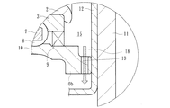
図1は、本発明に係る車輪用軸受装置の第1の実施形態を示す縦断面図、図2は、図1の要部拡大図である。なお、以下の説明では、車両に組み付けた状態で車両の外側寄りとなる側をアウター側(図1の左側)、中央寄り側をインナー側(図1の右側)という。
Hereinafter, embodiments of the present invention will be described in detail with reference to the drawings.
FIG. 1 is a longitudinal sectional view showing a first embodiment of a wheel bearing device according to the present invention, and FIG. 2 is an enlarged view of a main part of FIG. In the following description, the side closer to the outer side of the vehicle when assembled to the vehicle is referred to as the outer side (left side in FIG. 1), and the side closer to the center is referred to as the inner side (right side in FIG. 1).
この車輪用軸受装置は従動輪側の第3世代と称され、内方部材1と外方部材10、および両部材1、10間に転動自在に収容された複列の転動体(ボール)6、6とを備えている。内方部材1は、ハブ輪2と、このハブ輪2に所定のシメシロを介して圧入された内輪3とからなる。
This wheel bearing device is referred to as the third generation on the driven wheel side, and is a double row rolling element (ball) accommodated between the
ハブ輪2は、アウター側の端部に車輪(図示せず)を取り付けるための車輪取付フランジ4を一体に有し、この車輪取付フランジ4の円周等配位置に車輪を固定するためのハブボルト5が植設されると共に、車輪取付フランジ4のハブボルト5間には円孔4aが形成されている。この円孔4aによってハブ輪2の軽量化を図ることができる。また、ハブ輪2の外周には一方(アウター側)の内側転走面2aと、この内側転走面2aから軸方向に延びる小径段部2bが形成されている。そして、外周に他方(インナー側)の内側転走面3aが形成された内輪3がこの小径段部2bに圧入され、さらに、小径段部2bの端部を径方向外方に塑性変形させて形成した加締部2cにより、所定の軸受予圧が付与された状態で、ハブ輪2に対して内輪3が軸方向に固定されている。
The
ハブ輪2は、S53C等の炭素0.40〜0.80重量%を含む中高炭素鋼(JIS規格のSC系機械構造用炭素鋼)で形成され、アウター側の内側転走面2aをはじめ、後述するアウター側のシール8のシールランド部となる車輪取付フランジ4のインナー側の基部4bから小径段部2bに亙って高周波焼入れによって表面硬さを58〜64HRCの範囲に硬化処理されている。なお、加締部2cは、鍛造後の素材表面硬さ25HRC以下の未焼入れ部とされている。こうした硬化処理によりハブ輪2の強度が向上すると共に、シールランド部となる基部4bの摩耗や内輪3の嵌合面となる小径段部2bのフレッティング摩耗が抑制されて耐久性が向上する。また、加締部2cの加工性を向上させ、塑性変形によるクラック等の発生を防止することができる。なお、内輪3および転動体6はSUJ2等からなる高炭素クロム鋼からなり、芯部まで58〜64HRCの範囲に硬化処理されている。
The
外方部材10は、外周に車体(図示せず)に取り付けるための車体取付フランジ10bを一体に有し、内周に複列の外側転走面10a、10aが一体に形成されている。この外方部材10は、ハブ輪2と同様、S53C等の炭素0.40〜0.80重量%を含む中高炭素鋼で形成され、複列の外側転走面10a、10aが高周波焼入れによって表面硬さを58〜64HRCの範囲に硬化処理されている。そして、それぞれの転走面10a、2aと10a、3a間に複列の転動体6、6が収容され、保持器7、7によりこれら複列の転動体6、6が転動自在に保持されている。また、外方部材10と内方部材1との間に形成される環状空間の開口部にはシール8、9が装着され、軸受内部に封入された潤滑グリースの漏洩と、外部から雨水やダスト等が軸受内部に侵入するのを防止している。
The
ここでは、ハブ輪2の外周に直接内側転走面2aが形成された第3世代と呼称される車輪用軸受装置を例示したが、本発明に係る車輪用軸受装置はこうした構造に限定されず、例えば、図示はしないが、ハブ輪の小径段部に一対の内輪を圧入した、第2世代構造であっても良い。また、転動体6、6をボールとした複列アンギュラ玉軸受で構成された車輪用軸受を例示したが、これに限らず転動体に円すいころを使用した複列円すいころ軸受で構成されていても良い。
Here, the wheel bearing device referred to as the third generation in which the
ここで、外方部材10の外周にナックル11と嵌合するためのパイロット部が形成されておらず、ナックル11に突き合わせ状態で、車体取付フランジ10bがボルト(図示せず)を介して接合されている。すなわち、外方部材10のインナー側の開口部がナックル11によって閉塞されている。
Here, the pilot part for fitting with the
本実施形態では、外方部材10の車体取付フランジ10bとナックル11がドラムブレーキを構成するバックプレート12を介して接合されている。外方部材10における車体取付フランジ10bの路面から最も近い側の周方向一箇所に、径方向に貫通してドレーン孔13が形成されると共に、路面から最も遠い側の周方向一箇所に、径方向に貫通して空気抜き孔14が形成され、外方部材10とバックプレート12との間に形成される閉塞空間15と外部とを連通させている。これにより、ドレーン孔13から異物が閉塞空間15に雨水やダスト等の異物が侵入するのを防止すると共に、車体取付フランジ10bとバックプレート12との接合部から異物が侵入しても、空気抜き孔14によって閉塞空間15の内圧が常に大気圧となり、閉塞空間15に異物が残留することなくドレーン孔13から容易に排出することができる。
In the present embodiment, the vehicle
なお、空気抜き孔14は、路面から最も遠い側の周方向一箇所に限らず、路面から遠い側であれば複数箇所に設けても良い。さらに、この空気抜き孔14は、ドレーン孔13と違って泥水等によって詰る可能性が低いため、その孔径はドレーン孔13に比べ小径に、可能な限り小さくするのが好ましい。これにより、この空気抜き孔14から雨水やダスト等の異物が内部に侵入するのを最小限に抑えることができる。
The air vent holes 14 are not limited to one place in the circumferential direction on the side farthest from the road surface, and may be provided at a plurality of places as long as they are far from the road surface. Further, unlike the
さらに、本実施形態では、ナックル11およびバックプレート12の路面から最も遠い側の周方向一箇所に、車輪の回転速度を検出するための回転速度センサ(図示せず)のセンサ取付孔16、17が形成されている。このセンサ取付孔16、17と回転速度センサとの嵌合部に空気が流通する程度の僅かな隙間を設けることにより、前述した空気抜き孔14と同様の効果を得ることができる。また、通常、このセンサ取付孔16、17にOリング等のシールリングを介して回転速度センサが装着されるが、例えば、このシールリングを廃止することによっても空気抜き孔14と同様の効果を得ることができる。
Furthermore, in this embodiment,
図2に拡大して示すように、外方部材10における車体取付フランジ10bのインナー側の端部内周には環状の凹所18が形成されている。そして、この凹所18と外部とを連通するようにドレーン孔13が形成されている。これにより、外部から閉塞空間15に侵入した雨水やダスト等の異物は重力によって下方に流動し、シール9の近傍に残留することなくこの凹所18に滞留し、容易に、かつ速やかに外部に排出されるので、シール9の密封性を高めることができる。なお、本実施形態では、バックプレート12を介して外方部材10とナックル11が接合された構造を例示したが、無論、外方部材10とナックル11が直接接合された構造であっても良い。また、前述したドレーン孔13および空気抜き孔14は、円孔で構成されたものを例示したが、必ずしも円孔である必要はなく、矩形であってもまゆ形や長円形状であっても良い。
As shown in an enlarged view in FIG. 2, an
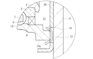
図3は、本発明に係る車輪用軸受装置の第2の実施形態を示す縦断面図、図4は、図3のIV−IV線から見た矢視図、図5は、図3の要部拡大図である。なお、この実施形態は前述した実施形態と基本的にはドレーン孔の構成が異なるのみで、その他同一部品同一部位あるいは同様の機能を有する部品や部位には同じ符号を付してその詳細な説明を省略する。 FIG. 3 is a longitudinal sectional view showing a second embodiment of the wheel bearing device according to the present invention, FIG. 4 is a view taken along the line IV-IV in FIG. 3, and FIG. FIG. This embodiment basically differs from the above-described embodiment only in the configuration of the drain hole, and other detailed descriptions of the same parts and parts having the same functions or parts having the same functions are denoted by the same reference numerals. Is omitted.
本実施形態では、図3に示すように、前述した第1の実施形態と同様、外方部材19の外周にナックル11と嵌合するためのパイロット部が形成されておらず、ナックル11に突き合わせ状態で、車体取付フランジ19aがバックプレート20を介してボルト(図示せず)によってナックル11に接合されている。
In the present embodiment, as shown in FIG. 3, the pilot portion for fitting with the
本実施形態では、図4に示すように、バックプレート20に複数(ここでは4個)のボルト孔20aとセンサ取付孔16が形成されると共に、路面から最も近い側の周方向一箇所にドレーン孔21と、路面から最も遠い側の少なくとも周方向一箇所に、空気抜き孔22がそれぞれ形成されている。これらのドレーン孔21と空気抜き孔22は、外方部材19における車体取付フランジ19aの端面位置に形成され、孔径はその端面幅よりも大径に形成されているので、外方部材19とバックプレート20との間に形成される閉塞空間15と外部とを連通することができる。これにより、図5に示すように、外部から閉塞空間15に侵入した雨水やダスト等の異物は重力によって下方に流動し、シール9の近傍に残留することなくこの凹所18に滞留し、容易に、かつ速やかに外部に排出される。さらに、ドレーン孔21と空気抜き孔22が、バックプレート20のプレス加工時に同時に形成されているため、機械加工による追加工が不要となって低コスト化を図ることができる。
In the present embodiment, as shown in FIG. 4, a plurality (four in this case) of bolt holes 20 a and
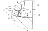
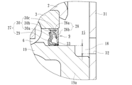
図6は、本発明に係る車輪用軸受装置の第3の実施形態を示す縦断面図、図7は、図6の要部拡大図、図8は、図7の変形例を示す要部拡大図、図9は、さらに他の変形例を示す要部拡大図である。なお、この実施形態は前述した第2の実施形態と基本的にはナックルとドレーン孔の構成が異なるのみで、その他同一部品同一部位あるいは同様の機能を有する部品や部位には同じ符号を付してその詳細な説明を省略する。 6 is a longitudinal sectional view showing a third embodiment of the wheel bearing device according to the present invention, FIG. 7 is an enlarged view of a main part of FIG. 6, and FIG. 8 is an enlarged main part of a modification of FIG. FIG. 9 is an enlarged view of a main part showing still another modification. This embodiment basically differs from the second embodiment described above only in the configuration of the knuckle and the drain hole, and the same reference numerals are given to the same parts or parts having the same functions. Detailed description thereof will be omitted.
本実施形態では、前述した第1の実施形態と同様、図6に示すように、外方部材19の外周にナックル23と嵌合するためのパイロット部が形成されておらず、ナックル23に突き合わせ状態で、車体取付フランジ19aがバックプレート24を介してボルト(図示せず)によってナックル23に接合されている。
In the present embodiment, as in the first embodiment described above, as shown in FIG. 6, a pilot portion for fitting with the
本実施形態では、ナックル23の路面から最も近い側に通し孔25が形成されると共に、バックプレート24の路面から最も近い側の周方向一箇所にドレーン孔26が形成されている。このドレーン孔26は、通し孔25の路面側の縁部に偏って配置され、通し孔25よりも小径に形成されている。これにより、図7に示すように、外部から閉塞空間15に侵入した雨水やダスト等の異物が重力によって下方の凹所18に流動し、ドレーン孔26から外部に排出される際、ドレーン孔26の上方に空気通路が形成され、実質的に閉塞空間15と外部とを連通することができる。したがって、外部の大気圧の影響を受けず、異物はこのドレーン孔26から通し孔25を介して外部に容易に排出されることができる。
In the present embodiment, a through
ここで、インナー側のシール9が、図8に示すように、断面が略L字状をなして互いに対向配置された環状のシール板27とスリンガ28とからなるパックシールで構成されている場合、すなわち、シール板27が、外方部材19の端部内周に圧入される芯金29と、この芯金29に一体に加硫接着され、サイドリップ30aと、このサイドリップ30aの内径側に二股状に形成されたグリースリップ30bと中間リップ30cとを有するシール部材30とからなると共に、スリンガ28が、内輪3の外径に圧入される円筒部28aと、この円筒部28aから径方向外方に延びる立板部28bとからなり、シール部材30のサイドリップ30aが立板部28bに摺接され、グリースリップ30bと中間リップ30cが円筒部28aに摺接されている。この場合、バックプレート31のドレーン孔32の位置をサイドリップ30aの摺接位置よりも下方、すなわち路面側に配置することにより、雨水やダスト等の異物がシール9のラビリンス隙間33より侵入したとしてもサイドリップ30aの摺接位置までは到達せず、異物はこのドレーン孔32を通して外部に排出される。したがって、密封性を向上させると共に、シール9の耐久性を高めることができる。
Here, as shown in FIG. 8, the
また、図9に示すように、外方部材19における車体取付フランジ19aのインナー側の端部内周に環状の凹所18が形成されている場合、バックプレート31のドレーン孔32の位置をシール板27の嵌合面よりも下方に配置することにより、雨水やダスト等の異物がシール9のラビリンス隙間33から侵入するのを防止することができ、異物はこのドレーン孔32を通して外部に排出される。したがって、密封性をさらに向上させると共に、シール9の耐久性を一層高めることができる。
As shown in FIG. 9, when the
以上、本発明の実施の形態について説明を行ったが、本発明はこうした実施の形態に何等限定されるものではなく、あくまで例示であって、本発明の要旨を逸脱しない範囲内において、さらに種々なる形態で実施し得ることは勿論のことであり、本発明の範囲は、特許請求の範囲の記載によって示され、さらに特許請求の範囲に記載の均等の意味、および範囲内のすべての変更を含む。 The embodiment of the present invention has been described above, but the present invention is not limited to such an embodiment, and is merely an example, and various modifications can be made without departing from the scope of the present invention. Of course, the scope of the present invention is indicated by the description of the scope of claims, and further, the equivalent meanings described in the scope of claims and all modifications within the scope of the scope of the present invention are included. Including.
本発明に係る車輪用軸受装置は従動輪側で、外方部材の外周にナックルと嵌合するためのパイロット部が形成されておらず、ナックルに突き合わせ状態で、車体取付フランジがボルトを介して接合される内輪回転タイプの第2世代または第3世代構造の車輪用軸受装置に適用できる。 In the wheel bearing device according to the present invention, the pilot wheel for fitting with the knuckle is not formed on the outer periphery of the outer member on the driven wheel side, and the vehicle body mounting flange is connected to the knuckle via the bolt. The present invention can be applied to an inner ring rotating type second-generation or third-generation wheel bearing device to be joined.
1・・・・・・・・・・・・内方部材
2・・・・・・・・・・・・ハブ輪
2a、3a・・・・・・・・内側転走面
2b・・・・・・・・・・・小径段部
2c・・・・・・・・・・・加締部
3・・・・・・・・・・・・内輪
4・・・・・・・・・・・・車輪取付フランジ
4a・・・・・・・・・・・円孔
4b・・・・・・・・・・・車輪取付フランジのインナー側の基部
5・・・・・・・・・・・・ハブボルト
6・・・・・・・・・・・・転動体
7・・・・・・・・・・・・保持器
8・・・・・・・・・・・・アウター側のシール
9・・・・・・・・・・・・インナー側のシール
10、19・・・・・・・・外方部材
10a・・・・・・・・・・外側転走面
10b、19a・・・・・・車体取付フランジ
11、23・・・・・・・・ナックル
12、20、24、31・・バックプレート
13、21、26、32・・ドレーン孔
14、22・・・・・・・・空気抜き孔
15・・・・・・・・・・・閉塞空間
16、17・・・・・・・・センサ取付孔
18・・・・・・・・・・・凹所
20a・・・・・・・・・・ボルト孔
25・・・・・・・・・・・通し孔
27・・・・・・・・・・・シール板
28・・・・・・・・・・・スリンガ
28a・・・・・・・・・・円筒部
28b・・・・・・・・・・立板部
29・・・・・・・・・・・芯金
30・・・・・・・・・・・シール部材
30a・・・・・・・・・・サイドリップ
30b・・・・・・・・・・グリースリップ
30c・・・・・・・・・・中間リップ
33・・・・・・・・・・・ラビリンス隙間
51・・・・・・・・・・・内方部材
52・・・・・・・・・・・ハブ輪
52a、53a・・・・・・内側転走面
52b・・・・・・・・・・小径段部
52c・・・・・・・・・・加締部
53・・・・・・・・・・・内輪
54・・・・・・・・・・・車輪取付フランジ
55・・・・・・・・・・・ハブボルト
56・・・・・・・・・・・ボール
57・・・・・・・・・・・保持器
58、59・・・・・・・・シール
60・・・・・・・・・・・外方部材
60a・・・・・・・・・・外側転走面
60b・・・・・・・・・・車体取付フランジ
61・・・・・・・・・・・ナックル
61a・・・・・・・・・・底部
62・・・・・・・・・・・ドレーン孔
63・・・・・・・・・・・閉塞空間
1 ....
Claims (10)
一端部に車輪取付フランジを一体に有し、この車輪取付フランジから軸方向に延びる小径段部が形成されたハブ輪、およびこのハブ輪の小径段部に圧入された少なくとも一つの内輪からなり、外周に前記複列の外側転走面に対向する複列の内側転走面が形成された内方部材と、
この内方部材と前記外方部材の両転走面間に保持器を介して転動自在に収容された複列の転動体と、
前記外方部材と内方部材との間に形成される環状空間の開口部に装着されたシールとを備え、
前記車体取付フランジとナックルとが突き合わせ状態で、前記外方部材が当該ナックルにボルトを介して接合され、前記外方部材のインナー側の開口部が前記ナックルによって閉塞された従動輪側の車輪用軸受装置において、
前記外方部材の車体取付フランジのインナー側の端部が前記内方部材の端部よりも軸方向インナー側に突出し、当該車体取付フランジのインナー側の端部内周に、前記シールのうちインナー側のシールの嵌合面より大径の環状の凹所が形成され、この凹所と外部とを連通するように、前記車体取付フランジとナックルの接合部にドレーン孔が形成され、このドレーン孔が路面から最も近い側の周方向一箇所に配置されると共に、前記外方部材とナックルとの間に形成される閉塞空間と外部とを連通する空気抜き孔が形成され、この空気抜き孔が路面から最も遠い側に配置され、当該空気抜き孔と前記ドレーン孔が軸方向同じ位置に形成されていることを特徴とする車輪用軸受装置。 An outer member integrally having a vehicle body mounting flange attached to a knuckle constituting a suspension device on the outer periphery, and an outer rolling surface of a double row integrally formed on the inner periphery;
It has a wheel mounting flange integrally at one end, a hub wheel formed with a small diameter step portion extending in the axial direction from the wheel mounting flange, and at least one inner ring press-fitted into the small diameter step portion of the hub wheel, An inner member in which a double row inner rolling surface facing the outer row rolling surface of the double row is formed on the outer periphery;
A double row rolling element housed between the rolling surfaces of the inner member and the outer member so as to be freely rollable via a cage;
A seal attached to an opening of an annular space formed between the outer member and the inner member;
For the wheel on the driven wheel side in which the outer member is joined to the knuckle via a bolt in a state where the vehicle body mounting flange and the knuckle are abutted, and the opening on the inner side of the outer member is closed by the knuckle In the bearing device,
The inner side end of the vehicle body mounting flange of the outer member protrudes inward in the axial direction from the end of the inner member, and the inner side of the seal on the inner periphery of the inner side end of the vehicle body mounting flange. An annular recess having a larger diameter than the fitting surface of the seal is formed, and a drain hole is formed at the joint between the vehicle body mounting flange and the knuckle so as to communicate the recess with the outside. while being circumferentially arranged one place closest from the road surface, air vent hole communicating with the closed space and the outside is formed between the outer member and the knuckle are formed, most air vent hole from the road surface A wheel bearing device, wherein the wheel bearing device is disposed on a far side, and the air vent hole and the drain hole are formed at the same position in the axial direction .
Priority Applications (1)
| Application Number | Priority Date | Filing Date | Title |
|---|---|---|---|
| JP2008145276A JP5317168B2 (en) | 2008-06-03 | 2008-06-03 | Wheel bearing device |
Applications Claiming Priority (1)
| Application Number | Priority Date | Filing Date | Title |
|---|---|---|---|
| JP2008145276A JP5317168B2 (en) | 2008-06-03 | 2008-06-03 | Wheel bearing device |
Publications (2)
| Publication Number | Publication Date |
|---|---|
| JP2009293651A JP2009293651A (en) | 2009-12-17 |
| JP5317168B2 true JP5317168B2 (en) | 2013-10-16 |
Family
ID=41542009
Family Applications (1)
| Application Number | Title | Priority Date | Filing Date |
|---|---|---|---|
| JP2008145276A Expired - Fee Related JP5317168B2 (en) | 2008-06-03 | 2008-06-03 | Wheel bearing device |
Country Status (1)
| Country | Link |
|---|---|
| JP (1) | JP5317168B2 (en) |
Families Citing this family (3)
| Publication number | Priority date | Publication date | Assignee | Title |
|---|---|---|---|---|
| KR101324030B1 (en) | 2012-07-23 | 2013-11-01 | 주식회사 제우스 | Bearing housing having exhaust line of foreign substance |
| JP6402532B2 (en) * | 2014-08-18 | 2018-10-10 | 日本精工株式会社 | Rolling bearing unit for wheel support |
| DE102016223910A1 (en) * | 2016-12-01 | 2017-03-02 | Audi Ag | Wheel bearing arrangement for a motor vehicle |
Family Cites Families (6)
| Publication number | Priority date | Publication date | Assignee | Title |
|---|---|---|---|---|
| JPS61103596U (en) * | 1984-12-14 | 1986-07-01 | ||
| JP2542589Y2 (en) * | 1991-05-27 | 1997-07-30 | 愛三工業株式会社 | Water pump |
| JP2002362106A (en) * | 2001-06-08 | 2002-12-18 | Nissan Motor Co Ltd | Wheel supporting structure |
| JP2005188632A (en) * | 2003-12-25 | 2005-07-14 | Ntn Corp | Bearing device for wheel |
| JP2005331429A (en) * | 2004-05-21 | 2005-12-02 | Ntn Corp | Rolling bearing unit with encoder |
| JP5158664B2 (en) * | 2006-03-06 | 2013-03-06 | Ntn株式会社 | Wheel bearing device |
-
2008
- 2008-06-03 JP JP2008145276A patent/JP5317168B2/en not_active Expired - Fee Related
Also Published As
| Publication number | Publication date |
|---|---|
| JP2009293651A (en) | 2009-12-17 |
Similar Documents
| Publication | Publication Date | Title |
|---|---|---|
| WO2010013439A1 (en) | Wheel-bearing device | |
| JP2008121839A (en) | Bearing device for wheel | |
| JP2010053893A (en) | Wheel-bearing device | |
| JP5468751B2 (en) | Wheel bearing device | |
| JP4345988B2 (en) | Wheel bearing device | |
| JP5158664B2 (en) | Wheel bearing device | |
| JP5179841B2 (en) | Wheel bearing device | |
| JP2013044420A (en) | Wheel bearing device | |
| JP5317168B2 (en) | Wheel bearing device | |
| JP2008057712A (en) | Wheel bearing device | |
| JP2007331661A (en) | Bearing device for wheel | |
| JP2013223869A (en) | Wheel bearing device and method for manufacturing the same | |
| JP2008032067A (en) | Bearing device for wheel | |
| JP2007100828A (en) | Bearing device for wheel | |
| JP5468753B2 (en) | Wheel bearing device | |
| JP2007187218A (en) | Bearing device for wheel | |
| JP2007100844A (en) | Bearing device for wheel | |
| JP2008095766A (en) | Wheel bearing | |
| JP4812112B2 (en) | Wheel bearing device | |
| JP5988738B2 (en) | Wheel bearing device | |
| JP2012056528A (en) | Bearing device for wheel | |
| JP2010127296A (en) | Wheel bearing device | |
| JP5273845B2 (en) | Wheel bearing device | |
| JP2010043670A (en) | Wheel-bearing device | |
| JP2007303651A (en) | Bearing device for wheel |
Legal Events
| Date | Code | Title | Description |
|---|---|---|---|
| A621 | Written request for application examination |
Free format text: JAPANESE INTERMEDIATE CODE: A621 Effective date: 20110602 |
|
| A977 | Report on retrieval |
Free format text: JAPANESE INTERMEDIATE CODE: A971007 Effective date: 20120510 |
|
| A131 | Notification of reasons for refusal |
Free format text: JAPANESE INTERMEDIATE CODE: A131 Effective date: 20120521 |
|
| A521 | Request for written amendment filed |
Free format text: JAPANESE INTERMEDIATE CODE: A523 Effective date: 20120712 |
|
| A02 | Decision of refusal |
Free format text: JAPANESE INTERMEDIATE CODE: A02 Effective date: 20130204 |
|
| A521 | Request for written amendment filed |
Free format text: JAPANESE INTERMEDIATE CODE: A523 Effective date: 20130402 |
|
| A911 | Transfer to examiner for re-examination before appeal (zenchi) |
Free format text: JAPANESE INTERMEDIATE CODE: A911 Effective date: 20130409 |
|
| TRDD | Decision of grant or rejection written | ||
| A01 | Written decision to grant a patent or to grant a registration (utility model) |
Free format text: JAPANESE INTERMEDIATE CODE: A01 Effective date: 20130704 |
|
| A61 | First payment of annual fees (during grant procedure) |
Free format text: JAPANESE INTERMEDIATE CODE: A61 Effective date: 20130704 |
|
| R150 | Certificate of patent or registration of utility model |
Ref document number: 5317168 Country of ref document: JP Free format text: JAPANESE INTERMEDIATE CODE: R150 Free format text: JAPANESE INTERMEDIATE CODE: R150 |
|
| R250 | Receipt of annual fees |
Free format text: JAPANESE INTERMEDIATE CODE: R250 |
|
| R250 | Receipt of annual fees |
Free format text: JAPANESE INTERMEDIATE CODE: R250 |
|
| R250 | Receipt of annual fees |
Free format text: JAPANESE INTERMEDIATE CODE: R250 |
|
| R250 | Receipt of annual fees |
Free format text: JAPANESE INTERMEDIATE CODE: R250 |
|
| R250 | Receipt of annual fees |
Free format text: JAPANESE INTERMEDIATE CODE: R250 |
|
| LAPS | Cancellation because of no payment of annual fees |