JP4204337B2 - Pipe fitting method - Google Patents
Pipe fitting method Download PDFInfo
- Publication number
- JP4204337B2 JP4204337B2 JP2003024106A JP2003024106A JP4204337B2 JP 4204337 B2 JP4204337 B2 JP 4204337B2 JP 2003024106 A JP2003024106 A JP 2003024106A JP 2003024106 A JP2003024106 A JP 2003024106A JP 4204337 B2 JP4204337 B2 JP 4204337B2
- Authority
- JP
- Japan
- Prior art keywords
- pipe
- tube
- peripheral surface
- joint
- cut
- Prior art date
- Legal status (The legal status is an assumption and is not a legal conclusion. Google has not performed a legal analysis and makes no representation as to the accuracy of the status listed.)
- Expired - Lifetime
Links
Images


Description
【0001】
【発明の属する技術分野】
本発明は、水道工事等の配管工事現場に搬入された規定寸法の直管状の流体管を施工現場で実測された配管寸法に基づいて切断した際に生ずる使用側又は未使用側の切管など、挿口管部の外周面が直管状に形成されている接続管を用いて耐震性に優れた継手構造を製作するための技術に関する。
【0002】
【従来の技術】
水道工事等の配管工事を考察すると、工事の大部分は、設計に基づいて現場に搬入された各種の配管器材を所定の手順で接続することにより行なわれるが、一部は、施工現場毎に異なる配管寸法差に基づいて、現場に搬入された直管状の流体管を切断し、この切管を接続する工法が採られている。
【0003】
そして、配管寸法に切断された使用対象の切管の切断端部を、耐震性に優れた管継手構造の挿口管部に構成するためには、例えば、図10、図11に示すように、施工現場において、切管50の切断端部に、先端側ほど小径となる挿入ガイド用のテーパー面52と、受口管51の内周面に嵌合保持されているロックリング53と管軸芯X方向から当接するC字状の抜止め用リング54を装着するための環状の取付け溝55とを切削加工したのち、この切管50の取付け溝55に、拡径操作されたC字状の抜止め用リング54を装着し、この抜止め用リング54の両端部とそれらに亘って架け渡される外れ止め用の結合ピース56とを、それぞれ冶具にて所定姿勢に固定した状態でリベット57により固定連結する方法が採られている。
【0004】
また、他方の切管は、切断加工箇所の施工現場では使用されることがなく、他の施工現場で使用するためには、その搬入先で上述と同様な加工を施す必要がある。
【0005】
【発明が解決しようとする課題】
しかしながら、切管50の切断端部を耐震性に優れた管継手構造の挿口管部に構成するためには、施工現場で上述のような煩雑な加工を施す必要があり、特に、抜止め用リング54の装着不良が生じると、所期の離脱防止効果が大きく低下するため、取付け溝55を高精度に加工する必要があるとともに、抜止め用リング54の装着にも多くの手間が必要であるため、切管50の製造コストが高騰化するとともに、加工期間も長くなっていた。
【0006】
本発明は、上述の実状に鑑みて為されたものであって、その主たる課題は、切管である挿口管部の外周面が直管状に形成されている接続管に対する施工現場での煩雑な加工を極力少なくすることにより、耐震性に優れた管継手構造の製造をコスト面及び工期面で有利に実施することのできる有用な管継手方法を提供する点にある。
【0007】
【課題を解決するための手段】
本発明の請求項1による管継手方法の特徴構成は、一端側に受口管部と他端側に挿口管部とを備えた継手管と、施工現場で所定寸法に切断加工して製作された外周面が直管状の切断端部を備えた切管とを用いて、
前記継手管の受口管部に対して管軸芯方向から前記直管状の切断端部を挿入接続可能な前記切管に、これの外周面と前記継手管の受口管部の内周面との間を密封する弾性シール材と、前記切管の外周面に対して径方向から喰込み移動可能な抜止め部材及び両管の相対離脱移動に連れて抜止め部材を管径方向内方側に喰込み移動させる喰込み誘導手段を備えた押輪とを外装し、
前記継手管の受口管部に対して前記切管の切断端部を差し込み接続したのち、
前記切管に外装された押輪と前記継手管の受口管部とに亘って装着された締結手段の締付け操作により、押輪と前記継手管の受口管部とを管軸芯方向から引き寄せながら締付け連結するとともに、その締付け連結に連れて押輪で弾性シール材を密封状態に押圧し、
更に、前記継手管の挿口管部の外周面の先端部に設けられた円環状の抜け止め突起と、当該挿口管部に嵌合接続される他の受口管部の内周面に形成された円環状の取付け溝に設けられた拡径側に拡径変形可能な係止部材及び当該係止部材を前記他の受口管部と同軸芯状態に保持する弾性保持リングとを備えた離脱防止手段により、前記継手管の挿口管部と前記他の受口管部とが相対離脱移動したとき、管軸芯方向から互いに接当してそれ以上の離脱移動を阻止する点にある。
【0008】
上記特徴構成によれば、施工現場で所定寸法に切断加工して製作された切管である、挿口管部(切断端部、以下同じ)の外周面が直管状に形成されている接続管(切管、以下同じ)を耐震性に優れた管継手構造の挿口管として用いるに、接続管の挿口管部を、継手管の一端側に形成された受口管部に挿入接続したのち、接続管に外装されている押輪と受口管部とを締結手段にて締付け固定すると、この締付け固定操作に伴う押輪と受口管部との管軸芯方向での相対近接移動により、接続管に外装されている弾性シール材が、接続管の外周面と受口管部の内周面との間で密封状態に押圧される。
【0009】
継手管の受口管部と押輪とが固定連結された状態では、地震や不等沈下等に起因して接続管と継手管に相対離脱方向の外力が作用しても、押輪に装備されている抜止め部材が、喰込み誘導手段によって管径方向内方側に喰込み移動され、接続管と継手管との接続が強力に維持される。
【0010】
また、継手管の他端側の挿口管部とそれに嵌合接続される他の受口管部とに対して、地震や不等沈下等に起因して相対離脱方向の外力が作用しても、継手管の挿口管部の外周面の先端部に設けられた円環状の抜け止め突起と、当該挿口管部に嵌合接続される他の受口管部の内周面に形成された円環状の取付け溝に設けられた拡径側に拡径変形可能な係止部材及び当該係止部材を他の受口管部と同軸芯状態に保持する弾性保持リングとを備えた離脱防止手段により、管軸芯方向から互いに接当して継手管の挿口管部と他の受口管部との離脱移動を強力に阻止することができる。
【0011】
それ故に、継手管の受口管部に接続管の挿口管部を挿入接続して、これら両管を押輪及び締結手段で抜止め固定するだけであるため、接続管の挿口管部に対する加工としても、挿口管部の一端側に対してバリ取りや面取り等の簡易な加工を施すだけで済む。
【0012】
従って、切管である挿口管部の外周面が直管状に形成されている接続管に対する施工現場での加工としてもバリ取り等の簡易な加工だけで済み、加工後は継手管に組み付けるだけでよいので、接続管に対する施工現場での煩雑な加工を極力少なくすることにより、耐震性に優れた管継手構造の製造をコスト面及び工期面で有利に実施することができる。
【0013】
本発明の請求項2による管継手方法の特徴構成は、一端側に受口管部と他端側に挿口管部とを備えた継手管と、施工現場で所定寸法に切断加工して製作された外周面が直管状の切断端部を備えた切管とを用いて、
前記継手管の受口管部に対して管軸芯方向から前記直管状の切断端部を挿入接続可能な前記切管に、これの外周面と前記継手管の受口管部の内周面との間を密封する弾性シール材と、前記切管の外周面に対して径方向から喰込み移動可能な抜止め部材と、抜止め部材を径方向内方に押圧可能な締付け具を組付けたのち、
前記継手管の受口管部に対して前記切管の切断端部を差し込み接続し、締付け具を締付け操作して抜止め部材を前記切管の外周面に喰込ませるとともに、締付け具と抜止め部材との間に設けた喰込み誘導手段により、両管の相対離脱移動に連れて抜止め部材を管径方向内方側に喰込み移動させ、
更に、前記継手管の挿口管部の外周面の先端部に設けられた円環状の抜け止め突起と、当該挿口管部に嵌合接続される他の受口管部の内周面に形成された円環状の取付け溝に設けられた拡径側に拡径変形可能な係止部材及び当該係止部材を前記他の受口管部と同軸芯状態に保持する弾性保持リングとを備えた離脱防止手段により、前記継手管の挿口管部と前記他の受口管部とが相対離脱移動したとき、管軸芯方向から互いに接当してそれ以上の離脱移動を阻止する点にある。
【0014】
上記特徴構成によれば、施工現場で所定寸法に切断加工して製作された切管である、挿口管部(切断端部、以下同じ)の外周面が直管状に形成されている接続管(切管、以下同じ)を耐震性に優れた管継手構造の挿口管として用いるに、接続管の挿口管部を、継手管の一端側に形成された受口管部に挿入接続すると、この挿入接続によって弾性シール材が、挿口管部の外周面と受口管部の内周面との間で密封状態に押圧される。次に、締付け具を締付け操作して抜止め部材を接続管の外周面に対して径方向から喰込み移動させることにより、通常の範囲内の外力が作用しても、継手管の受口管部に対して接続管の挿口管部が離脱移動することはない。
【0015】
そして、継手管の受口管部と接続管の挿口管部とが固定連結された状態では、地震や不等沈下等に起因して接続管と継手管とに相対離脱方向の外力が作用しても、締付け具と抜止め部材との間に設けた喰込み誘導手段により、喰込み状態にある抜止め部材が更に管径方向内方側に喰込み移動され、接続管と継手管との接続が強力に維持される。
【0016】
また、継手管の他端側の挿口管部とそれに嵌合接続される他の受口管部とに対して、地震や不等沈下等に起因して相対離脱方向の外力が作用しても、継手管の挿口管部の外周面の先端部に設けられた円環状の抜け止め突起と、当該挿口管部に嵌合接続される他の受口管部の内周面に形成された円環状の取付け溝に設けられた拡径側に拡径変形可能な係止部材及び当該係止部材を他の受口管部と同軸芯状態に保持する弾性保持リングとを備えた離脱防止手段により、管軸芯方向から互いに接当して継手管の挿口管部と他の受口管部との離脱移動を強力に阻止することができる。
【0017】
それ故に、継手管の受口管部に接続管の挿口管部を挿入接続したのち、締付け具を締付け操作して両管を抜止め固定するだけであるため、接続管の挿口管部に対する加工としても、挿口管部の一端側に対してバリ取りや面取り等の簡易な加工を施すだけで済む。
【0018】
従って、切管である挿口管部の外周面が直管状に形成されている接続管に対する施工現場での加工としてもバリ取り等の簡易な加工だけで済み、加工後は継手管に組み付けるだけでよいので、接続管に対する施工現場での煩雑な加工を極力少なくすることにより、耐震性に優れた管継手構造の製造をコスト面及び工期面で有利に実施することができる。
【0019】
本発明の管継手方法においては、前記離脱防止手段に、継手管の他端側管部とそれに嵌合接続される他の管部との管軸芯方向での一定範囲内での相対移動を許容する融通が設けられていてもよい。
【0020】
これによれば、地震や不等沈下等に起因する管軸芯方向の外力を吸収するべく、両管部の管軸芯方向での一定範囲内での相対移動を許容する融通を設けるにあたっても、継手管の他端側の挿口管部とそれに嵌合接続される他の受口管部との間に構成される離脱防止手段に設けてあるが故に、切管である接続管に対する施工現場での加工としては簡易な面取り加工だけで済み、より耐震性の優れた管継手構造の製造をコスト面及び工期面で有利に実施することができる。
【0021】
本発明の管継手方法においては、前記抜止め部材が、押輪の周方向複数箇所に組付けられているとともに、各抜止め部材の喰込み先端縁が、管軸芯方向視において接続管の外周面の半径と同一又は略同一の半径で弧状に形成されていてもよい。
【0022】
これによれば、抜止め部材の喰込み先端縁が、接続管の外周面の半径と同一の半径で弧状に形成されている場合には、抜止め部材の喰込み先端縁全体が、接続管の外周面に対して均等に喰込む。
【0023】
また、抜止め部材の喰込み先端縁が、接続管の外周面の半径よりも僅かに大きな半径で弧状に形成されている場合には、抜止め部材の喰込み先端縁の周方向中央部が接続管の外周面に最初に喰込むものの、喰込み先端縁における周方向中央部での喰込み量と周方向両端部での喰込み量との差を小さくすることができる。
【0024】
更に、抜止め部材の喰込み先端縁が、接続管の外周面の半径よりも僅かに小さな半径で弧状に形成されている場合には、抜止め部材の喰込み先端縁の周方向両端部が接続管の外周面に最初に喰込むため、喰込み先端縁の周方向中央部が接続管の外周面に最初に喰込む場合に比較して、喰込み力を周方向で分散させ易く、しかも、喰込み先端縁における周方向両端部での喰込み量と周方向中央部での喰込み量との差を小さくすることができる。
【0025】
従って、各抜止め部材の喰込み先端縁の形状を切管である接続管の外径に基づいて改造するだけの経済的な改造をもって、所定の離脱防止機能を確実に発揮させながらも、接続管の内周面に施されている防蝕用ライニング層に割れや剥離等の損傷が発生することを良好に抑制することができる。
【0026】
【発明の実施の形態】
〔第1実施形態〕
図1〜図4は、水道管やガス管等の流体管の配管系に用いられる管継手構造及び管継手方法を示し、鋳鉄製の継手管1の一端側に形成された受口管部1Aに、挿口管部2Aの外周面が凹凸の無い直管状に形成されている接続管2の一例で、直管状の流体管(例えば、日本工業規格(JIS)等で規定された遠心鋳造により製作された鋳鉄管) を施工現場で所定寸法に切断加工して製作された使用側の切管2の一端側(切断側)の挿口管部(切断端部)2Aを、管軸芯X方向から挿入接続し、この挿入接続された切管2に、受口管部1Aの内周面1aと切管2の外周面2aとの間を密封可能な円環状の合成ゴム製の弾性シール材3と、該弾性シール材3を管軸芯X方向から押圧して密封状態(水密状態)にまで圧縮可能な鋳鉄製の押輪4が外装されているとともに、押輪4と継手管1の受口管部1Aとを管軸芯X方向から互いに引き寄せながら固定連結する締結手段5が設けられている。
【0027】
更に、継手管1の他端側に形成された挿口管部1Bとそれに嵌合接続される他の流体管6の受口管部6Aとの間には、両管部1B,6Aが管軸芯X方向に沿って相対離脱移動したとき、管軸芯X方向から互いに接当してそれ以上の離脱移動を阻止する離脱防止手段Aと、継手管1の挿口管部1Bと他の流体管6の受口管部6Aとを同軸芯状態に維持する屈曲防止手段C、及び、挿口管部1Bの外周面と受口管部6Aの内周面との間を密封可能な円環状の合成ゴム製の弾性シール材10が設けられているとともに、継手管1の挿口管部1Bの外周面で、かつ、周方向に等間隔を隔てた複数箇所(当該実施形態では4箇所)には、受口管部6Aの端面と管軸芯X方向から接当する接合用突起1Eが形成されている。
【0028】
前記締結手段5は、継手管1の受口管部1Aの端部に一体形成された連結フランジ部1Cの円周方向複数箇所に形成されたボルト挿通孔1b、及び、押輪4の外周面の周方向複数箇所(当該実施形態では8箇所)に突出形成された連結突片4Aのボルト挿通孔4aとのうち、管軸芯X方向で相対向するボルト挿通孔1b、4aに亘って挿入されるT字状のボルト5Aと、該ボルト5Aのネジ軸部に螺合されるナット5Bから構成されていて、このボルト5A・ナット5Bの締付け操作に伴う押輪4と継手管1の受口管部1Aとの管軸芯X方向での相対近接移動により、押輪4と継手管1の受口管部1Aとを締付け固定するとともに、押輪4の管軸芯X方向の一端部に形成された円環状のシール押圧部4Bで弾性シール材3を圧縮変形させ、受口管部1Aの内周面1aと切管2の挿口管部2Aの外周面2aとの間を密封する。
【0029】
前記押輪4は、切管2の挿口管部2Aに対して管軸芯X方向から外嵌装着自在な円環状に一体成形されていて、その内周面側の周方向に等間隔を隔てた複数箇所(当該実施形態では8箇所)には、管径方向内方に向って開口する凹部4Cが形成され、各凹部4C内には、切管2の外周面2aに喰い込み可能な金属製の抜止め部材7が、管径方向内方に喰込み移動自在に装着されているとともに、各抜止め部材7と押輪4との間には、継手管1の受口管部1Aと切管2との相対離脱移動に連れて抜止め部材7を管径方向内方側に喰込み移動させる喰込み誘導手段Bが設けられている。
【0030】
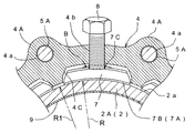
前記喰込み誘導手段Bは、抜止め部材7の外側面の周方向中央部に形成された受口管部1A側ほど大径となる傾斜受け面7Cと、この傾斜受け面7Cに対する直交方向(垂直方向)に沿って押輪4の各凹部4Cに臨む部位に形成されたネジ孔4b、及び、各ネジ孔4bに対して径方向外方から螺合することにより、傾斜受け面7Cを介して抜止め部材7を、切管2の外周面2a側、つまり、管径方向内方に向って押圧する押圧ネジ部材の一例である押圧ボルト8とから構成されている。
【0031】
前記各抜止め部材7の内側面(内周面)の管軸芯X方向両端部には、図4に示すように、周方向で連続する三角突条の喰込み突起7A、7Bが一体形成され、各喰込み突起7A、7Bの管周方向での長さが同一又は略同一に構成されているとともに、各喰込み突起7A、7Bの喰込み先端縁が、管軸芯X方向視において切管2の外周面2aの半径R1と同一又は略同一の半径Rで弧状に形成されている。
【0032】
つまり、各喰込み突起7A、7Bの喰込み先端縁を弧状に形成するための半径Rは、切管2の外周面2aの半径をR1としたとき、(R1+2mm未満)〜(R1−2mm)の範囲内に、好ましくは、(R1+1mm)〜(R1−1mm)の範囲内に、最も好ましくはR1と同一径に構成されている。
【0033】
そして、喰込み突起7A、7Bの喰込み先端縁が、切管2の外周面2aの半径R1よりも+2mm未満の僅かに大きな半径Rで弧状に形成されている場合には、喰込み突起7A、7Bの喰込み先端縁の周方向中央部が切管2の外周面2aに最初に喰込むものの、喰込み先端縁における周方向中央部での喰込み量と周方向両端部での喰込み量との差を小さくすることができ、更に、喰込み突起7A、7Bの喰込み先端縁が、切管2の外周面2aの半径R1よりも+1mm以内の僅かに大きな半径Rで弧状に形成されている場合には、喰込み先端縁における周方向中央部での喰込み量と周方向両端部での喰込み量との差を更に小さくすることができる。
【0034】
また、喰込み突起7A、7Bの喰込み先端縁が、切管2の外周面2aの半径R1よりも−2mm以内の僅かに小さな半径Rで弧状に形成されている場合には、喰込み突起7A、7Bの喰込み先端縁の周方向両端部が切管2の外周面2aに最初に喰込むため、喰込み先端縁の周方向中央部が切管2の外周面2aに最初に喰込む場合に比較して、喰込み力を周方向で分散させ易く、しかも、喰込み先端縁における周方向両端部での喰込み量と周方向中央部での喰込み量との差を小さくすることができ、更に、喰込み突起7A、7Bの喰込み先端縁が、切管2の外周面2aの半径R1よりも−1mm以内の僅かに小さな半径Rで弧状に形成されている場合には、喰込み先端縁における周方向両端部での喰込み量と周方向中央部での喰込み量との差を更に小さくすることができる。
【0035】
更に、喰込み突起7A、7Bの喰込み先端縁が、切管2の外周面2aの半径R1と同一の半径Rで弧状に形成されている場合には、喰込み突起7A、7Bの喰込み先端縁全体が、切管2の外周面2aに対して均等に喰込むことになり、喰込み先端縁における周方向中央部での喰込み量と周方向両端部での喰込み量とを等しくすることができる。
【0036】
それ故に、所定の離脱防止機能を確実に発揮させながらも、切管2の内周面に施される防蝕用ライニング層9に割れや剥離等の損傷が発生することを良好に抑制することができる。
【0037】
また、図4に示すように、前記押圧ボルト8の螺合軸芯(ネジ軸芯)Zと管軸芯Xに対して直交する垂直線Yとの成す角度θが、15〜11度の傾斜角度範囲内に、好ましくは、14〜12度の傾斜角度範囲内に、最も好ましくは13度の傾斜角度に構成されている。
【0038】
そして、地震や不等沈下等に起因する離脱方向への外力によって、押輪4に螺合装着された押圧ボルト8の先端部と抜止め部材7の傾斜受け面7Cとが管軸芯X方向で相対移動したとき、この相対移動量に対する抜止め部材7の径方向内方への喰込み量を適度に小さくすることができるから、押輪4の管軸芯X方向での小型化(小幅化)を図りながらも、切管2の防蝕用ライニング層9に割れや剥離等の損傷が発生することを良好に抑制することができる。
【0039】
前記離脱防止手段Aを構成するに、図1に示すように、他の流体管6の受口管部6Aの内周面に形成された円環状の取付け溝6aに、管軸芯X方向視において略Cの字状に形成された拡径側に弾性変形可能な金属製の係止部材12と、これの拡径変形を許容する状態で該係止部材12を受口管部6Aと同軸芯状態に保持する弾性保持リング13とを装着するとともに、継手管1の挿口管部1Bの外周面の先端部には、地震や不等沈下等に起因して両管部1B,6Aが一定以上に相対離脱移動したとき、係止部材12に対して管軸芯X方向から接当してそれ以上の両管部1B,6Aの相対離脱移動を阻止する円環状の抜止め突起1Dが一体形成されている。
【0040】
前記屈曲防止手段Cを構成するに、図1に示すように、継手管1の挿口管部1Bの外周面で、かつ、接合用突起1Eに連続する部位及びそれらの周方向中間部位の各々には、接合用突起1Eよりも突出代の小なる突起部1Fを一体形成するとともに、受口管部6Aには、挿口管部1Bの複数の突起部1Fに接触する拡径側に弾性変形可能な金属製の屈曲防止用リング15と、この屈曲防止用リング15の周方向複数箇所を管径方向内方に押圧して縮径変形させる複数本のセットボルト16とから構成されている。
【0041】
また、前記受口管部6Aの内周面で、かつ、屈曲防止用リング15と係止部材12との間に位置する部位には、弾性シール材10を保持する環状のシール保持溝6bが形成されている。
【0042】
次に、切管継手方法について説明する。
まず、施工現場で所定寸法に切断加工して製作された使用側の切管2の一側端に、受口管部1Aの内周面1aとの間を密封する弾性シール材3が損傷しないように、また、切管2の挿口管部2Aをスムースに挿入できるように、切管2の一側端の角部が環状傾斜面2bとなるように面取り加工を施したのち、この切管2の挿口管部2Aに、弾性シール材3と抜止め部材7が装着された押輪4とを外装し、この切管2の挿口管部2Aを、継手管1の一端側に形成された受口管部1Aに管軸芯X方向から挿入接続する。
【0043】
次に、継手管1の連結フランジ部1Cと押輪4の連結突片4Aとを、締結手段5のボルト5A・ナット5Bで管軸芯X方向から引き寄せながら締付け固定すると、このボルト5A・ナット5Bの締付け操作に伴う押輪4と継手管1の受口管部1Aとの管軸芯X方向での相対近接移動により、受口管部1Aの内周面1aと切管2の挿口管部2Aの外周面2aとの間に入り込んだ弾性シール材3が、押輪4のシール押圧部4Bで管軸芯X方向から押圧圧縮され、弾性シール材3によって受口管部1Aの内周面1aと切管2の挿口管部2Aの外周面2aとの間が密封される。
【0044】
押輪4と継手管1の受口管部1Aとが固定連結されると、喰込み誘導手段Bの各押圧ボルト8を螺合操作して、押輪4の各凹部4Cに装着されている抜止め部材7を、それらの各喰込み突起7A、7Bが切管2の外周面2aに喰込む状態に調整する。
【0045】
この状態では、各押圧ボルト8の先端が抜止め部材7の傾斜受け面7Cに接当しているため、地震や不等沈下等に起因する離脱方向の外力が作用すると、継手管1の受口管部1Aと切管2との相対離脱移動に連れて各抜止め部材7が管径方向内方側に喰込み移動され、継手管1の受口管部1Aと切管2との接続が強力に維持される。
【0046】
他方、屈曲防止リング15、セットボルト16、弾性シール材10、係止部材12、弾性保持リング13が装着されている他の流体管6の受口管部6Aに対して、継手管1の挿口管部1Bを挿入すると、この挿口管部1Bの抜止め突起1Dに形成されたテーパー状の挿入ガイド面1dにより、係止部材12が弾性保持リング13の弾性復元力に抗して拡径変形され、挿口管部1Bの抜止め突起1Dが通過した時点で係止部材12が元の状態に復帰し、挿口管部1Bの抜止め突起1Dと係止部材12とが管軸芯X方向で係合可能となるため、継手管1の挿口管部1Bと他の流体管6の受口管部6Aとの相対離脱移動が強力に阻止される。
【0047】
また、図1に示すように、挿口管部1Bの接合用突起1Eが受口管部6Aの端面に接当した状態では、挿口管部1Bの抜止め突起1Dと係止部材12との間に若干の融通(空隙)Sが形成されていて、その融通Sの範囲内で継手管1の挿口管部1Bと他の流体管6の受口管部6Aとの管軸芯X方向での一定範囲内での相対移動を許容するように構成されている。
【0048】
〔第2実施形態〕
上述の第1実施形態では、前記離脱防止手段Aに、継手管1の他端側の挿口管部1Bとそれに管軸芯X方向から嵌合接続される他の流体管6の受口管部6Aとの管軸芯X方向での一定範囲内での相対移動を許容する若干の融通Sを設けたが、図5に示すように、第1実施形態における屈曲防止手段C及び接合用突起1Eを削除して、両管部1B,6Aの大きな伸縮を許容する融通Sを構成してもよい。
尚、その他の構成は、第1実施形態で説明した構成と同一であるから、同一の構成箇所には、第1実施形態と同一の番号を付記してそれの説明は省略する。
【0049】
〔第3実施形態〕
図6は、継手管1の他端側に形成された挿口管部1Bとそれに管軸芯X方向から嵌合接続される他の流体管6の受口管部6Aとの間に設けられる離脱防止手段Aの別実施形態を示し、他の流体管6の受口管部6Aの内周面に形成された円環状の取付け溝6cに、管軸芯X方向視において略Cの字状に形成された拡径側に弾性変形可能な金属製の係止部材18が装着され、この係止部材18の周方向複数箇所を径方向内方に押圧して、係止部材18の内周面側部分が挿口管部1Bの外周面に形成された環状の係止溝1e内に係合する状態にまで縮径変形させる複数本のセットボルト19が、取付け溝6cの周方向複数箇所に連通する状態で受口管部6Aに形成されたネジ孔6dに螺合されているとともに、受口管部6Aの外周面から外方に突出する各セットボルト19の突出ネジ部にはキャップ20が螺合されている。
【0050】
また、この第3実施形態では、受口管部6Aの端部に一体形成された連結フランジ部6Bには、挿口管部1Bの外周面と受口管部6Aの内周面との間を密封可能な円環状の弾性シール材21を密封状態にまで管軸芯方向から押圧する押輪22が、複数のボルト23・ナット24を介して脱着自在に固定連結されている。
尚、その他の構成は、第1実施形態で説明した構成と同一であるから、同一の構成箇所には、第1実施形態と同一の番号を付記してそれの説明は省略する。
【0051】
〔第4実施形態〕
上述の各実施形態では、継手管1の他端側の管部を挿口管部1Bに構成し、それに管軸芯X方向から嵌合接続される他の流体管6の管部を受口管部6Aに構成したが、図7に示すように、この継手管1の他端側の管部を受口管部1Gに構成し、それに管軸芯X方向から嵌合接続される他の流体管6の管部を挿口管部6Dに構成して実施してもよい。
【0052】
前記継手管1の他端側に形成された受口管部1Gとそれに嵌合接続される他の流体管6の挿口管部6Dとの間に設けられる離脱防止手段Aを構成するに、受口管部1Gの内周面に形成された円環状の取付け溝1fに、管軸芯X方向視において略Cの字状に形成された拡径側に弾性変形可能な金属製の係止部材26と、これの拡径変形を許容する状態で該係止部材26を受口管部1Gと同軸芯状態に保持する弾性保持リング27とを装着するとともに、他の流体管6の挿口管部6Dの外周面の先端部には、地震や不等沈下等に起因して両管部1G,6Dが一定以上に相対離脱移動したとき、係止部材26に対して管軸芯X方向から接当してそれ以上の両管部1G,6Dの相対離脱移動を阻止する円環状の抜止め突起6Eが一体形成されている。
【0053】
また、受口管部1Gの内周面には、挿口管部6Dの外周面と受口管部1Gの内周面との間を密封可能な円環状の合成ゴム製の弾性シール材28を保持する環状のシール保持溝1gが形成されている。
尚、その他の構成は、第1実施形態で説明した構成と同一であるから、同一の構成箇所には、第1実施形態と同一の番号を付記してそれの説明は省略する。
【0054】
〔第5実施形態〕
上述の各実施形態では、切管2の一側端の角部が環状傾斜面2bとなるように面取り加工を施したが、図8に示すように、前記切管2の一側端部に、先端側ほど小径で、かつ、基端側が切管2の外径と同一叉はほぼ同一となるテーパー状の挿入ガイド面29aを備えた金属製又は合成樹脂製の挿入ガイド部材29を管軸芯X方向から圧入状態で嵌合装着したのち、この挿入ガイド部材29が装着された切管2の挿口管部2Aを継手管1の受口管部1Aに挿入接続するように構成してもよい。
【0055】
そのため、挿入ガイド部材29の挿入ガイド面29aを利用して、受口管部1Aへの挿入接続操作をスムースに行うことができるから、切管2の挿口管部2Aに面取り加工を施す必要がなく、切管2の再利用コストの低廉化及び工期の短縮化を促進することができる。
【0056】
尚、その他の構成は、第1実施形態で説明した構成と同一であるから、同一の構成箇所には、第1実施形態と同一の番号を付記してそれの説明は省略する。
【0057】
〔第6実施形態〕
図9は、水道管やガス管等の流体管の配管系において、鋳鉄製の継手管1の一端側に形成された受口管部1Aに、挿口管部2Aの外周面が凹凸の無い直管状に形成されている接続管2の一例で、直管状の流体管(例えば、日本工業規格(JIS)等で規定された遠心鋳造により製作された鋳鉄管) を施工現場で所定寸法に切断加工して製作された使用側の切管2の一端側(切断側)の挿口管部(切断端部)2Aを管軸芯X方向から挿入接続してある別の管継手構造及び管継手方法を示し、継手管1の受口管部1Aには、切管2の挿口管部2Aの外周面2aと受口管部1Aの内周面1aとの間を密封する円環状の合成ゴム製の弾性シール材3と、切管2の外周面2aに対して管径方向から喰込み移動可能な抜止め部材7と、抜止め部材7を管径方向内方に押圧可能な締付け具30が組付けられている。
【0058】
更に、継手管1の他端側に形成された挿口管部1Bとそれに嵌合接続される他の流体管6の受口管部6Aとの間には、両管部1B,6Aが管軸芯X方向に沿って相対離脱移動したとき、管軸芯X方向から互いに接当してそれ以上の離脱移動を阻止する離脱防止手段Aと、継手管1の挿口管部1Bと他の流体管6の受口管部6Aとを同軸芯状態に維持する屈曲防止手段C、及び、挿口管部1Bの外周面と受口管部6Aの内周面との間を密封可能な円環状の合成ゴム製の弾性シール材10が設けられているとともに、継手管1の挿口管部1Bの外周面で、かつ、周方向に等間隔を隔てた複数箇所(当該実施形態では4箇所)には、受口管部6Aの端面と管軸芯X方向から接当する接合用突起1Eが形成されている。
【0059】
前記継手管1の受口管部1Aの端部側で、周方向に所定間隔を隔てた複数箇所には、抜止め部材7を管径方向内方に向かって移動自在に収納する凹部1Hが形成されているとともに、各凹部1Hの天井壁部分に形成されたネジ孔1Jには、締付け具30の一例で、受口管部1Aの外周側から抜止め部材7を管径方向内方に向って押圧する押圧ボルトが螺合され、更に、受口管部1Aの内周面には、弾性シール材3を保持する環状のシール保持溝1Kが形成されている。
【0060】
前記抜止め部材7の外側面の周方向中央部に、受口管部1Aの奥側ほど大径となる傾斜受け面7Cを形成するとともに、各凹部1Hのネジ孔1J及び押圧ボルト30を、抜止め部材7の傾斜受け面7Cに対して直角に当て付け可能な傾斜姿勢に形成して、押圧ボルト30と抜止め部材7との間に、継手管1の受口管部1Aと切管2の挿口管部2Aとの相対離脱移動に連れて抜止め部材7を管径方向内方側に喰込み移動させる喰込み誘導手段Bが構成されている。
【0061】
前記各抜止め部材7の内側面(内周面)の管軸芯X方向両端部には、周方向で連続する三角突条の喰込み突起7A、7Bが一体形成され、各喰込み突起7A、7Bの管周方向での長さが同一又は略同一に構成されているとともに、各喰込み突起7A、7Bの喰込み先端縁が、管軸芯X方向視において切管2の外周面2aの半径R1と同一又は略同一の半径Rで弧状に形成されている。
【0062】
また、図9に示すように、前記押圧ボルト8の螺合軸芯(ネジ軸芯)Zと管軸芯Xに対して直交する垂直線Yとの成す角度θが、15〜11度の傾斜角度範囲内に、好ましくは、14〜12度の傾斜角度範囲内に、最も好ましくは13度の傾斜角度に構成されている。
【0063】
前記離脱防止手段Aを構成するに、他の流体管6の受口管部6Aの内周面に形成された円環状の取付け溝6aに、管軸芯X方向視において略Cの字状に形成された拡径側に弾性変形可能な金属製の係止部材12と、これの拡径変形を許容する状態で該係止部材12を受口管部6Aと同軸芯状態に保持する弾性保持リング13を装着するとともに、継手管1の挿口管部1Bの外周面の先端部には、地震や不等沈下等に起因して両管部1B,6Aが一定以上に相対離脱移動したとき、係止部材12に対して管軸芯X方向から接当してそれ以上の両管部1B,6Aの相対離脱移動を阻止する円環状の抜止め突起1Dが一体形成されている。
【0064】
前記屈曲防止手段Cを構成するに、継手管1の挿口管部1Bの外周面で、かつ、接合用突起1Eに連続する部位及びそれらの周方向中間部位の各々には、接合用突起1Eよりも突出代の小なる突起部1Fを一体形成するとともに、受口管部6Aには、挿口管部1Bの複数の突起部1Fに接触する拡径側に弾性変形可能な金属製の屈曲防止用リング15と、この屈曲防止用リング15の周方向複数箇所を管径方向内方に押圧して縮径変形させる複数本のセットボルト16とから構成されている。
【0065】
また、前記受口管部6Aの内周面で、かつ、屈曲防止用リング15と係止部材12との間に位置する部位には、弾性シール材10を保持する環状のシール保持溝6bが形成されている。
【0066】
次に、切管継手方法について説明する。
まず、施工現場で所定寸法に切断加工して製作された使用側の切管2の一側端に、受口管部1Aの内周面1aとの間を密封する弾性シール材3が損傷しないように、また、切管2の挿口管部2Aをスムースに挿入できるように、切管2の一側端の角部が環状傾斜面2bとなるように面取り加工を施すとともに、継手管1の受口管部1Aに、弾性シール材3、抜止め部材7、押圧ボルト30を装着したのち、切管2の挿口管部2Aを、継手管1の受口管部1Aに管軸芯X方向から挿入接続すると、この挿入接続によって弾性シール材3が、挿口管部2Aの外周面2aと受口管部1Aの内周面1aとの間で密封状態に圧縮される。
【0067】
次に、押圧ボルト30を締付け操作して、受口管部1Aの各凹部1H内に装着されている抜止め部材7を切管2の挿口管部2Aの外周面2aに対して管径方向から喰込み移動させることにより、通常の範囲内の外力が作用しても、継手管1の受口管部1Aに対して切管2の挿口管部2Aが離脱移動することはない。
【0068】
この状態では、各押圧ボルト8の先端が抜止め部材7の傾斜受け面7Cに接当しているため、地震や不等沈下等に起因する離脱方向の外力が作用すると、継手管1の受口管部1Aと切管2との相対離脱移動に連れて各抜止め部材7が管径方向内方側に喰込み移動され、継手管1の受口管部1Aと切管2の挿口管部2Aとの接続が強力に維持される。
【0069】
他方、屈曲防止リング15、セットボルト16、弾性シール材10、係止部材12、弾性保持リング13が装着されている他の流体管6の受口管部6Aに対して、継手管1の挿口管部1Bを挿入すると、この挿口管部1Bの抜止め突起1Dに形成されたテーパー状の挿入ガイド面1dにより、係止部材12が弾性保持リング13の弾性復元力に抗して拡径変形され、挿口管部1Bの抜止め突起1Dが通過した時点で係止部材12が元の状態に復帰し、挿口管部1Bの抜止め突起1Dと係止部材12とが管軸芯X方向で係合可能となるため、継手管1の挿口管部1Bと他の流体管6の受口管部6Aとの相対離脱移動が強力に阻止される。
【0070】
また、挿口管部1Bの接合用突起1Eが受口管部6Aの端面に接当した状態では、挿口管部1Bの抜止め突起1Dと係止部材12との間に若干の融通(空隙)Sが形成されていて、その融通Sの範囲内で継手管1の挿口管部1Bと他の流体管6の受口管部6Aとの管軸芯X方向での一定範囲内での相対移動を許容するように構成されている。
【0071】
尚、その他の構成は、第1実施形態で説明した構成と同一であるから、同一の構成箇所には、第1実施形態と同一の番号を付記してそれの説明は省略する。
【0072】
〔その他の実施形態〕
(1)上述の各実施形態では、前記喰込み誘導手段Bを、抜止め部材7の外側面に形成された傾斜受け面7Cと、押輪4に形成されたネジ孔4b又は受口管部1Aに形成されたネジ孔1J、及び、ネジ孔4b又は1Jに対して径方向外方から螺合することにより、傾斜受け面7Cを介して抜止め部材7を切管2の外周面2a側に押圧する押圧ボルト8又は30とから構成したが、抜止め部材7の傾斜受け面7Cと押圧ボルト8又は30の先端部との間に、傾斜受け面7Cに摺接する同一勾配の喰込みガイド面を備えた金属製の押え部材を介装して実施してもよい。
要するに、喰込み誘導手段Bとしては、切管2と受口管部1Aとの相対離脱移動に連れて抜止め部材7を管径方向内方側に喰込み移動させることのできるものであれば、如何なる構造のものを用いてもよい。
【0073】
(2)上述の第1実施形態では、前記押輪4を、切管2に対して管軸芯X方向から外嵌装着自在な円環状に一体成形したが、この押輪4を円周方向で複数に分割された複数個の分割押輪体から構成してもよい。
【0074】
(3)上述の第1〜第4実施形態では、切管2の一側端の角部が環状傾斜面2bとなるように面取り加工を施したが、このような面取り加工を省略して実施してもよい。
【0075】
(4)上述の第6実施形態では、継手管1の他端側に形成された挿口管部1Bとそれに嵌合接続される他の流体管6の受口管部6Aとの接合構造として、第1実施形態と同じ接続構造を採用したが、図5に示す第2実施形態の接続構造、第6図に示す第3実施形態の接続構造、図7に示す第4実施形態の接続構造の何れと組合わせて実施してもよい。
【0076】
(5)上述の第6実施形態では、切管2の一側端の角部が環状傾斜面2bとなるように面取り加工を施したが、図8に示す第5実施形態と同様に、前記切管2の一側端部に、先端側ほど小径で、かつ、基端側が切管2の外径と同一叉はほぼ同一となるテーパー状の挿入ガイド面29aを備えた金属製又は合成樹脂製の挿入ガイド部材29を管軸芯X方向から圧入状態で嵌合装着したのち、この挿入ガイド部材29が装着された切管2の挿口管部2Aを継手管1の受口管部1Aに挿入接続するように構成してもよい。
【図面の簡単な説明】
【図1】本発明の第1実施形態を示す切管接続後の断面側面図
【図2】図1におけるII−II線拡大断面図
【図3】押輪の要部の拡大断面正面図
【図4】押輪の要部の拡大断面側面図
【図5】本発明の第2実施形態を示す切管接続後の断面側面図
【図6】本発明の第3実施形態を示す切管接続後の断面側面図
【図7】本発明の第4実施形態を示す切管接続後の断面側面図
【図8】本発明の第5実施形態を示す切管接続後の要部の断面側面図
【図9】本発明の第6実施形態を示す切管接続後の要部の断面側面図
【図10】従来の切管継手構造を示す要部の断面側面図
【図11】固定連結後の抜止め用リングと結合ピースとの正面図
【符号の説明】
A 離脱防止手段
B 喰込み誘導手段
S 融通
X 管軸芯
1 継手管
1A 受口管部
1B 管部(挿口管部)
1G 管部(受口管部)
1a 内周面
2 切管
2A 一側端部
2a 外周面
3 弾性シール材
4 押輪
5 締結手段
6 他の流体管
6A 管部(受口管部)
6D 管部(挿口管部)
7 抜止め部材
29 挿入ガイド部材
29a 挿入ガイド面
30 締付け具(押圧ボルト)[0001]
BACKGROUND OF THE INVENTION
The present invention relates to a cut tube on the use side or the unused side that is generated when a straight tubular fluid pipe having a specified size carried into a pipe construction site such as waterworks is cut based on a pipe size actually measured on the construction site. The present invention relates to a technique for manufacturing a joint structure having excellent earthquake resistance using a connection pipe in which an outer peripheral surface of an insertion tube portion is formed in a straight tube shape.
[0002]
[Prior art]
Considering plumbing work such as waterworks, most of the work is done by connecting various piping equipment brought into the site based on the design according to a predetermined procedure, but part of it is done at each construction site. A method of cutting a straight tubular fluid pipe carried into the site and connecting the cut pipe based on a difference in dimension between different pipes has been adopted.
[0003]
And in order to comprise the cutting edge part of the cutting tube of the cut object used for the piping dimension in the insertion pipe part of the pipe joint structure excellent in earthquake resistance, as shown, for example in FIG. 10, FIG. At the construction site, a tapered surface 52 for an insertion guide having a smaller diameter toward the distal end side at the cut end portion of the
[0004]
In addition, the other cut tube is not used at the construction site of the cutting processing place, and in order to use it at another construction site, it is necessary to perform the same processing as described above at the carry-in destination.
[0005]
[Problems to be solved by the invention]
However, in order to configure the cut end portion of the
[0006]
The present invention has been made in view of the above circumstances, and its main problem is as follows.Cut tubeAdvantages in terms of cost and construction time of manufacturing a pipe joint structure with excellent earthquake resistance by minimizing complicated processing at the construction site for connecting pipes that have a straight tube-shaped outer peripheral surface The present invention provides a useful pipe joint method that can be implemented in the present invention.
[0007]
[Means for Solving the Problems]
The characteristic configuration of the pipe joint method according to
An outer peripheral surface of the cut tube that can be inserted and connected with the straight tubular cutting end portion from the tube axis direction to the receiving tube portion of the joint tube, and an inner peripheral surface of the receiving tube portion of the joint tube An elastic sealing material that seals between the tube, a retaining member that can move in the radial direction with respect to the outer peripheral surface of the cut tube, and a retaining member that moves inwardly in the tube radial direction along with the relative detachment movement of both tubes The press wheel equipped with the biting guidance means for biting and moving to the side,
After connecting the cut end of the cut tube to the receiving tube portion of the joint tube,
While pulling the push ring and the receiving pipe portion of the joint pipe from the tube axis direction by tightening operation of the fastening means mounted across the push ring externally mounted on the cut pipe and the receiving pipe section of the joint pipe With the tightening connection, the elastic sealing material is pressed in a sealed state with a push ring along with the tightening connection,
Furthermore, an annular retaining protrusion provided at the distal end portion of the outer peripheral surface of the insertion tube portion of the joint tube, and an inner peripheral surface of another receiving tube portion fitted and connected to the insertion tube portion A locking member capable of expanding and deforming on the diameter-enlarged side provided in the formed annular mounting groove, and an elastic holding ring that holds the locking member in a coaxial core state with the other receiving pipe portion. When the insertion tube portion of the joint tube and the other receiving tube portion move relative to each other by the separation preventing means, they come into contact with each other from the tube axis direction to prevent further separation movement.In the point.
[0008]
According to the above characteristic configuration, at the construction siteTo the specified dimensionsCuttingProcessed and manufacturedCut tubeIs, Intubation tube(Cut end, the same applies below)A connecting pipe whose outer peripheral surface is formed in a straight tube shape(Cut tube, the same applies hereinafter)Is used as an insertion tube of a pipe joint structure with excellent earthquake resistance, after inserting and connecting the insertion tube portion of the connection tube to the reception tube portion formed on one end side of the joint tube, When the presser wheel and the receiving tube are fastened and fixed by fastening means,UshiDue to the relative proximity movement of the ring and the receiving pipe part in the axial direction of the pipe, the elastic seal material sheathed on the connecting pipe is sealed between the outer peripheral surface of the connecting pipe and the inner peripheral face of the receiving pipe part. Pressed into the state.
[0009]
In a state where the receiving pipe part of the joint pipe and the press ring are fixedly connected, even if an external force in the relative separation direction acts on the connection pipe and the joint pipe due to an earthquake or uneven settlement, the press ring is equipped. The retaining member that has been removed is engulfed and moved inwardly in the pipe radial direction by the engulfing guidance means, and the connection between the connecting pipe and the joint pipe is maintained strongly.
[0010]
Also, the other end of the joint pipeInsertionPipe part and other fittings connected to itReceptacleEven if an external force in the direction of relative separation acts on the pipe part due to an earthquake or uneven settlement,An annular retaining protrusion provided at the distal end portion of the outer peripheral surface of the insertion tube portion of the joint tube, and an inner peripheral surface of another receiving tube portion that is fitted and connected to the insertion tube portion. A locking member capable of expanding and deforming on the diameter-enlarged side provided in the annular mounting groove, and an elastic holding ring that holds the locking member in a coaxial core state with another receiving pipe portion.Contact with each other from the tube axis direction by the separation prevention meansWith the insertion pipe part of the joint pipe and other receiving pipe partsIt is possible to strongly prevent the movement of separation.
[0011]
Therefore, the insertion tube portion of the connection tube is inserted and connected to the receiving tube portion of the joint tube, and both the tubes are simply secured by the push ring and the fastening means. As processing, it is only necessary to perform simple processing such as deburring and chamfering on one end side of the insertion tube portion.
[0012]
Therefore, the cut tubeIsAs the processing at the construction site for the connection pipe where the outer peripheral surface of the insertion tube part is formed in a straight tube shape, it is only necessary to perform simple processing such as deburring, etc.By minimizing troublesome processing at the construction site for connecting pipes,Manufacture of a pipe joint structure excellent in earthquake resistance can be carried out advantageously in terms of cost and construction period.
[0013]
The characteristic configuration of the pipe joint method according to
An outer peripheral surface of the cut tube that can be inserted and connected with the straight tubular cutting end portion from the tube axis direction to the receiving tube portion of the joint tube, and an inner peripheral surface of the receiving tube portion of the joint tube Assembling an elastic sealing material that seals between the outer peripheral surface of the cut tube, a retaining member that can move in the radial direction with respect to the outer peripheral surface of the cut tube, and a fastener that can press the retaining member radially inward After that
The cut end portion of the cut tube is inserted and connected to the receiving tube portion of the joint tube, and the clamping member is tightened so that the retaining member is caught in the outer peripheral surface of the cut tube, and the fastening tool and the disconnection portion are removed. With the biting guidance means provided between the stopper member and the relative separation movement of both pipes, the stopper member is bitten inwardly in the pipe radial direction,
Furthermore, an annular retaining protrusion provided at the distal end portion of the outer peripheral surface of the insertion tube portion of the joint tube, and an inner peripheral surface of another receiving tube portion fitted and connected to the insertion tube portion A locking member capable of expanding and deforming on the diameter-enlarged side provided in the formed annular mounting groove, and an elastic holding ring that holds the locking member in a coaxial core state with the other receiving pipe portion. When the insertion tube portion of the joint tube and the other receiving tube portion move relative to each other by the separation preventing means, they come into contact with each other from the tube axis direction to prevent further separation movement.In the point.
[0014]
According to the above characteristic configuration, at the construction siteTo the specified dimensionsCuttingProcessed and manufacturedCut tubeIs, Intubation tube(Cut end, the same applies below)A connecting pipe whose outer peripheral surface is formed in a straight tube shape(Cut tube, the same applies hereinafter)Is used as an insertion tube of a pipe joint structure with excellent earthquake resistance, and the insertion tube portion of the connection tube is inserted and connected to a receiving tube portion formed on one end side of the joint tube. The material is pressed in a sealed state between the outer peripheral surface of the insertion tube portion and the inner peripheral surface of the receiving tube portion. Next, even if an external force within the normal range is applied by tightening the fastener and moving the retaining member radially from the outer peripheral surface of the connecting pipe, the receiving pipe of the joint pipe The insertion tube portion of the connecting tube does not move away from the portion.
[0015]
In a state where the receiving pipe part of the joint pipe and the insertion pipe part of the connection pipe are fixedly connected, an external force in the relative separation direction acts on the connection pipe and the joint pipe due to an earthquake or uneven settlement. Even so, the biting guide means provided between the fastening tool and the retaining member causes the retaining member in the bitten state to further bite and move inward in the pipe radial direction, and the connecting pipe and the joint pipe Connection is maintained strongly.
[0016]
Also, the other end of the joint pipeInsertionPipe part and other fittings connected to itReceptacleEven if an external force in the direction of relative separation acts on the pipe part due to an earthquake or uneven settlement,An annular retaining protrusion provided at the distal end portion of the outer peripheral surface of the insertion tube portion of the joint tube, and an inner peripheral surface of another receiving tube portion that is fitted and connected to the insertion tube portion. A locking member capable of expanding and deforming on the diameter-enlarged side provided in the annular mounting groove, and an elastic holding ring that holds the locking member in a coaxial core state with another receiving pipe portion.Contact with each other from the tube axis direction by the separation prevention meansWith the insertion pipe part of the joint pipe and other receiving pipe partsIt is possible to strongly prevent the movement of separation.
[0017]
Therefore, after inserting and connecting the insertion tube portion of the connection tube to the receiving tube portion of the joint tube, it is only necessary to tighten and tighten the fastener to secure both tubes so that the insertion tube portion of the connection tube As for the processing for this, it is only necessary to perform simple processing such as deburring or chamfering on one end side of the insertion tube portion.
[0018]
Therefore, the cut tubeIsAs the processing at the construction site for the connection pipe where the outer peripheral surface of the insertion tube part is formed in a straight tube shape, it is only necessary to perform simple processing such as deburring, etc.By minimizing troublesome processing at the construction site for connecting pipes,Manufacture of a pipe joint structure excellent in earthquake resistance can be carried out advantageously in terms of cost and construction period.
[0019]
In the pipe joint method of the present invention,The disengagement prevention means is provided with the flexibility to allow relative movement within a certain range in the tube axis direction between the other end side pipe portion of the joint pipe and the other pipe portion fitted and connected thereto.May.
[0020]
thisAccording to the present invention, in order to absorb the external force in the tube axis direction caused by earthquakes, uneven settlement, etc., in providing the flexibility to allow relative movement within a certain range in the tube axis direction of both pipe parts, The other end of the joint pipeInsertionPipe part and other fittings connected to itReceptacleBecause it is provided in the separation prevention means configured between the pipe and the pipe,IsAs the processing at the construction site for the connecting pipe, only a simple chamfering process is required, and the manufacture of a pipe joint structure having more excellent earthquake resistance can be advantageously carried out in terms of cost and construction period.
[0021]
In the pipe joint method of the present invention,The retaining members are assembled at a plurality of locations in the circumferential direction of the press wheel, and the biting tip edges of the retaining members are the same as or substantially the same as the radius of the outer peripheral surface of the connecting tube in the tube axis direction view. It is formed in an arc shape with a radius ofMay.
[0022]
thisAccording to the above, when the biting tip edge of the retaining member is formed in an arc shape with the same radius as the outer peripheral surface of the connection pipe, the entire biting tip edge of the retaining member is Eat evenly with respect to the outer peripheral surface.
[0023]
Further, when the biting tip edge of the retaining member is formed in an arc shape with a radius slightly larger than the radius of the outer peripheral surface of the connection pipe, the circumferential central portion of the biting tip edge of the retaining member is Although it bites into the outer peripheral surface of a connection pipe first, the difference of the amount of biting in the circumferential center part in the biting tip edge and the amount of biting in the circumferential direction both ends can be made small.
[0024]
Further, when the biting tip edge of the retaining member is formed in an arc shape with a radius slightly smaller than the radius of the outer peripheral surface of the connection pipe, both ends in the circumferential direction of the biting tip edge of the retaining member are Compared to the case where the central part in the circumferential direction of the leading edge of the bite first bites into the outer peripheral surface of the connecting pipe because it bites into the outer peripheral surface of the connecting pipe first, it is easier to disperse the biting force in the circumferential direction. The difference between the amount of biting at both ends in the circumferential direction at the leading edge of the biting and the amount of biting at the central portion in the circumferential direction can be reduced.
[0025]
Therefore, the shape of the biting tip edge of each retaining member is the cut tube.IsWith economical modifications only based on the outer diameter of the connecting pipe, the anti-corrosion lining layer on the inner peripheral surface of the connecting pipe is cracked or peeled off, while ensuring the specified function of preventing separation. It is possible to satisfactorily suppress the occurrence of such damage.
[0026]
DETAILED DESCRIPTION OF THE INVENTION
[First Embodiment]
1 to 4 show a pipe joint structure and a pipe joint method used for a pipe system of a fluid pipe such as a water pipe or a gas pipe, and a receiving pipe portion 1A formed on one end side of a cast iron
[0027]
Further, between the insertion tube portion 1B formed on the other end side of the
[0028]
The fastening means 5 includes bolt insertion holes 1b formed at a plurality of locations in the circumferential direction of the connecting
[0029]
The
[0030]
The biting guidance means B includes an inclined receiving surface 7C having a larger diameter toward the receiving tube portion 1A side formed on the circumferential center portion of the outer side surface of the retaining
[0031]
As shown in FIG. 4,
[0032]
That is, the radius R for forming the biting tip edges of the biting
[0033]
When the leading edge of the biting
[0034]
Further, when the leading edge of the biting
[0035]
Further, when the biting tip edges of the biting
[0036]
Therefore, it is possible to satisfactorily suppress the occurrence of damage such as cracking or peeling in the corrosion-
[0037]
Further, as shown in FIG. 4, the angle θ formed by the screw shaft core (screw shaft core) Z of the
[0038]
And by the external force to the detachment direction resulting from an earthquake, unequal subsidence, etc., the front-end | tip part of the press volt |
[0039]
As shown in FIG. 1, the separation preventing means A is formed in an annular mounting groove 6a formed on the inner peripheral surface of the receiving pipe portion 6A of another
[0040]
As shown in FIG. 1, each of the bending prevention means C is formed on the outer peripheral surface of the insertion tube portion 1B of the
[0041]
Further, an annular seal holding groove 6b for holding the
[0042]
Next, the cut pipe joint method will be described.
First, the
[0043]
Next, when the connecting
[0044]
When the
[0045]
In this state, since the tip of each
[0046]
On the other hand, the
[0047]
Further, as shown in FIG. 1, in a state where the joining projection 1E of the insertion tube portion 1B is in contact with the end surface of the receiving tube portion 6A, the retaining projection 1D and the locking
[0048]
[Second Embodiment]
In the first embodiment described above, the separation preventing means A is connected to the insertion tube portion 1B on the other end side of the
In addition, since the other structure is the same as the structure demonstrated in 1st Embodiment, the same number is attached to the same structure location as 1st Embodiment, and the description is abbreviate | omitted.
[0049]
[Third Embodiment]
6 is provided between the insertion tube portion 1B formed on the other end side of the
[0050]
In the third embodiment, the connecting flange portion 6B formed integrally with the end portion of the receiving pipe portion 6A is provided between the outer peripheral surface of the insertion tube portion 1B and the inner peripheral surface of the receiving pipe portion 6A. A push ring 22 that presses an annular elastic sealing material 21 that can seal the tube from the tube axis direction to a sealed state is fixedly connected via a plurality of
In addition, since the other structure is the same as the structure demonstrated in 1st Embodiment, the same number is attached to the same structure location as 1st Embodiment, and the description is abbreviate | omitted.
[0051]
[Fourth Embodiment]
In each of the above-described embodiments, the tube portion on the other end side of the
[0052]
To constitute the separation preventing means A provided between the receiving pipe portion 1G formed on the other end side of the
[0053]
Further, on the inner peripheral surface of the receiving tube portion 1G, an annular synthetic rubber elastic sealing material 28 that can seal between the outer peripheral surface of the insertion tube portion 6D and the inner peripheral surface of the receiving tube portion 1G. An annular seal retaining groove 1g is formed.
In addition, since the other structure is the same as the structure demonstrated in 1st Embodiment, the same number is attached to the same structure location as 1st Embodiment, and the description is abbreviate | omitted.
[0054]
[Fifth Embodiment]
In each of the above-described embodiments, the chamfering process is performed so that the corner of one side end of the
[0055]
For this reason, the insertion guide surface 29a of the
[0056]
In addition, since the other structure is the same as the structure demonstrated in 1st Embodiment, the same number is attached to the same structure location as 1st Embodiment, and the description is abbreviate | omitted.
[0057]
[Sixth Embodiment]
FIG. 9 shows that in the piping system of fluid pipes such as water pipes and gas pipes, the receiving pipe part 1A formed on one end side of the cast-iron
[0058]
Further, between the insertion tube portion 1B formed on the other end side of the
[0059]
On the end side of the receiving pipe portion 1A of the
[0060]
At the center of the outer surface of the retaining
[0061]
[0062]
Further, as shown in FIG. 9, the angle θ formed by the screw shaft core (screw shaft core) Z of the
[0063]
The above-described detachment preventing means A is configured by an annular mounting groove 6a formed on the inner peripheral surface of the receiving pipe portion 6A of another
[0064]
To constitute the bending preventing means C, a joining projection 1E is provided on each of the outer peripheral surface of the insertion tube portion 1B of the
[0065]
Further, an annular seal holding groove 6b for holding the
[0066]
Next, the cut pipe joint method will be described.
First, the
[0067]
Next, by tightening the
[0068]
In this state, since the tip of each
[0069]
On the other hand, the
[0070]
In addition, in a state where the joining projection 1E of the insertion tube portion 1B is in contact with the end surface of the reception tube portion 6A, there is some flexibility between the retaining projection 1D of the insertion tube portion 1B and the locking member 12 ( Within a certain range in the tube axis X direction between the insertion tube portion 1B of the
[0071]
In addition, since the other structure is the same as the structure demonstrated in 1st Embodiment, the same number is attached to the same structure location as 1st Embodiment, and the description is abbreviate | omitted.
[0072]
[Other Embodiments]
(1) In each of the above-described embodiments, the biting guide means B includes the inclined receiving surface 7C formed on the outer surface of the retaining
In short, as the biting guidance means B, as long as the retaining
[0073]
(2) In the first embodiment described above, the
[0074]
(3) In the above-described first to fourth embodiments, the chamfering process is performed so that the corner portion at one side end of the
[0075]
(4) In the above-described sixth embodiment, as a joint structure between the insertion tube portion 1B formed on the other end side of the
[0076]
(5) In the above-described sixth embodiment, the chamfering process is performed so that the corner portion of one side end of the
[Brief description of the drawings]
FIG. 1 is a cross-sectional side view after cutting tube connection showing a first embodiment of the present invention.
FIG. 2 is an enlarged sectional view taken along line II-II in FIG.
FIG. 3 is an enlarged cross-sectional front view of the main part of the press ring
FIG. 4 is an enlarged cross-sectional side view of the main part of the push ring.
FIG. 5 is a cross-sectional side view after cutting tube connection showing a second embodiment of the present invention.
FIG. 6 is a cross-sectional side view after cutting tube connection showing a third embodiment of the present invention.
FIG. 7 is a cross-sectional side view after cutting tube connection showing a fourth embodiment of the present invention.
FIG. 8 is a cross-sectional side view of an essential part after connecting a cut tube showing a fifth embodiment of the present invention.
FIG. 9 is a cross-sectional side view of an essential part after connecting a cut tube showing a sixth embodiment of the present invention.
FIG. 10 is a cross-sectional side view of an essential part showing a conventional cut-tube joint structure.
FIG. 11 is a front view of a retaining ring and a coupling piece after fixed connection;
[Explanation of symbols]
A withdrawal prevention means
B Eating guidance means
S interchangeability
X Tube core
1 Fitting pipe
1A receiving pipe part
1B Tube (Inlet tube)
1G pipe part (receiving pipe part)
1a Inner peripheral surface
2 Cut pipe
2A One end
2a Outer peripheral surface
3 Elastic sealing material
4 wheel
5 fastening means
6 Other fluid pipes
6A Pipe part (receiving pipe part)
6D tube (inlet tube)
7 retaining member
29 Insertion guide member
29a Insertion guide surface
30 Fastener (Pressing bolt)
Claims (2)
前記継手管の受口管部に対して管軸芯方向から前記直管状の切断端部を挿入接続可能な前記切管に、これの外周面と前記継手管の受口管部の内周面との間を密封する弾性シール材と、前記切管の外周面に対して径方向から喰込み移動可能な抜止め部材及び両管の相対離脱移動に連れて抜止め部材を管径方向内方側に喰込み移動させる喰込み誘導手段を備えた押輪とを外装し、
前記継手管の受口管部に対して前記切管の切断端部を差し込み接続したのち、
前記切管に外装された押輪と前記継手管の受口管部とに亘って装着された締結手段の締付け操作により、押輪と前記継手管の受口管部とを管軸芯方向から引き寄せながら締付け連結するとともに、その締付け連結に連れて押輪で弾性シール材を密封状態に押圧し、
更に、前記継手管の挿口管部の外周面の先端部に設けられた円環状の抜け止め突起と、当該挿口管部に嵌合接続される他の受口管部の内周面に形成された円環状の取付け溝に設けられた拡径側に拡径変形可能な係止部材及び当該係止部材を前記他の受口管部と同軸芯状態に保持する弾性保持リングとを備えた離脱防止手段により、前記継手管の挿口管部と前記他の受口管部とが相対離脱移動したとき、管軸芯方向から互いに接当してそれ以上の離脱移動を阻止する管継手方法。 A joint pipe provided with a receiving pipe part on one end side and an insertion pipe part on the other end side, and a cutting pipe having an outer peripheral surface manufactured by cutting to a predetermined dimension at a construction site and having a straight tubular cutting end part. With a tube,
The joint tube receiving opening tube portion pipe axis direction from the insertable connecting cut ends of the straight tube of the cut pipe against the inner peripheral surface of the receiving pipe section of the joint pipe and this outer peripheral surface An elastic sealing material that seals between the tube , a retaining member that can move in the radial direction with respect to the outer peripheral surface of the cut tube , and a retaining member that moves inwardly in the tube radial direction along with the relative detachment movement of both tubes The press wheel equipped with the biting guidance means for biting and moving to the side,
After connecting insert the cut end of the cut pipe with respect to the socket pipe portion of the joint pipe,
The fastening operation of the fastening means mounted across the receiver pipe portion of the joint pipe and junk ring which is fitted on the cut pipe, while attracted to the receiver pipe portion of the the junk ring joint pipe from pipe axis direction With the tightening connection, the elastic sealing material is pressed in a sealed state with a push ring along with the tightening connection,
Further, an annular retaining projection provided on the distal end portion of the outer peripheral surface of the inserted pipe portion of the joint pipe, the inner peripheral surface of the other of the receiving pipe section to be fitted and connected to the inserted pipe section A locking member capable of expanding and deforming on the diameter-enlarged side provided in the formed annular mounting groove, and an elastic holding ring that holds the locking member in a coaxial core state with the other receiving pipe portion. by the release preventing means, when the inserted pipe portion of the joint pipe and said another receiver pipe portion are relatively detached moves, tube you prevent further withdrawal movement with Setto each other from pipe axis direction Joint method.
前記継手管の受口管部に対して管軸芯方向から前記直管状の切断端部を挿入接続可能な前記切管に、これの外周面と前記継手管の受口管部の内周面との間を密封する弾性シール材と、前記切管の外周面に対して径方向から喰込み移動可能な抜止め部材と、抜止め部材を径方向内方に押圧可能な締付け具を組付けたのち、
前記継手管の受口管部に対して前記切管の切断端部を差し込み接続し、締付け具を締付け操作して抜止め部材を前記切管の外周面に喰込ませるとともに、締付け具と抜止め部材との間に設けた喰込み誘導手段により、両管の相対離脱移動に連れて抜止め部材を管径方向内方側に喰込み移動させ、
更に、前記継手管の挿口管部の外周面の先端部に設けられた円環状の抜け止め突起と、当該挿口管部に嵌合接続される他の受口管部の内周面に形成された円環状の取付け溝に設けられた拡径側に拡径変形可能な係止部材及び当該係止部材を前記他の受口管部と同軸芯状態に保持する弾性保持リングとを備えた離脱防止手段により、前記継手管の挿口管部と前記他の受口管部とが相対離脱移動したとき、管軸芯方向から互いに接当してそれ以上の離脱移動を阻止する管継手方法。 A joint pipe provided with a receiving pipe part on one end side and an insertion pipe part on the other end side, and a cutting pipe having an outer peripheral surface manufactured by cutting to a predetermined dimension at a construction site and having a straight tubular cutting end part. With a tube,
The joint tube receiving opening tube portions in pairs to the pipe axis direction from the insertable connecting cut ends of the straight tube of the cut pipe, the inner periphery of the receiving pipe section of the joint pipe and this outer peripheral surface An elastic sealing material that seals between the surfaces, a retaining member that can move in a radial direction with respect to the outer peripheral surface of the cut tube , and a fastener that can press the retaining member radially inward. After attaching
Insert the cut end of the cut pipe was connected to the receiver pipe portion of the joint pipe, with Maseru喰込the retaining member is operated tightening the fastener to the outer peripheral surface of the cut pipe, fastener and unplug With the biting guidance means provided between the stopper member and the relative separation movement of both pipes, the stopper member is bitten inwardly in the pipe radial direction,
Further, an annular retaining projection provided on the distal end portion of the outer peripheral surface of the inserted pipe portion of the joint pipe, the inner peripheral surface of the other of the receiving pipe section to be fitted and connected to the inserted pipe section A locking member capable of expanding and deforming on the diameter-enlarged side provided in the formed annular mounting groove, and an elastic holding ring that holds the locking member in a coaxial core state with the other receiving pipe portion. by the release preventing means, when the inserted pipe portion of the joint pipe and said another receiver pipe portion are relatively detached moves, tube you prevent further withdrawal movement with Setto each other from pipe axis direction Joint method.
Priority Applications (1)
| Application Number | Priority Date | Filing Date | Title |
|---|---|---|---|
| JP2003024106A JP4204337B2 (en) | 2002-08-23 | 2003-01-31 | Pipe fitting method |
Applications Claiming Priority (2)
| Application Number | Priority Date | Filing Date | Title |
|---|---|---|---|
| JP2002243642 | 2002-08-23 | ||
| JP2003024106A JP4204337B2 (en) | 2002-08-23 | 2003-01-31 | Pipe fitting method |
Publications (2)
| Publication Number | Publication Date |
|---|---|
| JP2004138234A JP2004138234A (en) | 2004-05-13 |
| JP4204337B2 true JP4204337B2 (en) | 2009-01-07 |
Family
ID=32472615
Family Applications (1)
| Application Number | Title | Priority Date | Filing Date |
|---|---|---|---|
| JP2003024106A Expired - Lifetime JP4204337B2 (en) | 2002-08-23 | 2003-01-31 | Pipe fitting method |
Country Status (1)
| Country | Link |
|---|---|
| JP (1) | JP4204337B2 (en) |
Families Citing this family (3)
| Publication number | Priority date | Publication date | Assignee | Title |
|---|---|---|---|---|
| JP2010144809A (en) * | 2008-12-17 | 2010-07-01 | Cosmo Koki Co Ltd | Joint for pipe line restoration |
| JP5307599B2 (en) * | 2009-03-31 | 2013-10-02 | 株式会社水道技術開発機構 | Detachment prevention fitting |
| KR101073898B1 (en) * | 2011-07-21 | 2011-10-17 | 고용민 | One touch type pipe connection device having improved tensile force and easy connection |
-
2003
- 2003-01-31 JP JP2003024106A patent/JP4204337B2/en not_active Expired - Lifetime
Also Published As
| Publication number | Publication date |
|---|---|
| JP2004138234A (en) | 2004-05-13 |
Similar Documents
| Publication | Publication Date | Title |
|---|---|---|
| JP6623261B2 (en) | Pipe fitting | |
| WO1995033948A1 (en) | Mechanical joint pipe adapter | |
| WO1995033948A9 (en) | Mechanical joint pipe adapter | |
| CA2459637C (en) | Pipe coupling | |
| JP4939826B2 (en) | How to assemble pipe fittings | |
| US20030098584A1 (en) | Radial conduit coupling system and method | |
| JP4981783B2 (en) | Fluid pipe for fitting structure | |
| JP2003042359A (en) | Spacerless type pipe joint and packing ring used for the same | |
| JP4204337B2 (en) | Pipe fitting method | |
| JP5576691B2 (en) | Pipe fitting | |
| JP5192979B2 (en) | Pipe joint structure | |
| JP4542364B2 (en) | Pipe connection structure and installation method of in-pipe work machine to insertion tube | |
| JP2004347045A (en) | Expansion joint for stainless steel tube | |
| JP4261842B2 (en) | Residual pipe joint method and residual pipe joint structure | |
| JP2005090605A (en) | Piping connector | |
| JP7216407B2 (en) | Pipe joint structure | |
| JP2003014174A (en) | Conduit connecting device | |
| JP3904698B2 (en) | Tube fixing device | |
| JP2002295753A (en) | Pipe joint structure | |
| JP6605325B2 (en) | Tubular structure | |
| WO2018235615A1 (en) | Tubular structure | |
| JP7054518B2 (en) | Detachment prevention pipe joint and method to prevent disengagement of pipe joint | |
| JPH0731030Y2 (en) | Pipe joint with disconnection prevention function | |
| JPH0676790U (en) | Pipe fitting | |
| JPH11108267A (en) | Pipe joint |
Legal Events
| Date | Code | Title | Description |
|---|---|---|---|
| A621 | Written request for application examination |
Free format text: JAPANESE INTERMEDIATE CODE: A621 Effective date: 20060130 |
|
| A977 | Report on retrieval |
Free format text: JAPANESE INTERMEDIATE CODE: A971007 Effective date: 20080521 |
|
| A131 | Notification of reasons for refusal |
Free format text: JAPANESE INTERMEDIATE CODE: A131 Effective date: 20080529 |
|
| A521 | Request for written amendment filed |
Free format text: JAPANESE INTERMEDIATE CODE: A523 Effective date: 20080728 |
|
| TRDD | Decision of grant or rejection written | ||
| A01 | Written decision to grant a patent or to grant a registration (utility model) |
Free format text: JAPANESE INTERMEDIATE CODE: A01 Effective date: 20081002 |
|
| A01 | Written decision to grant a patent or to grant a registration (utility model) |
Free format text: JAPANESE INTERMEDIATE CODE: A01 |
|
| A61 | First payment of annual fees (during grant procedure) |
Free format text: JAPANESE INTERMEDIATE CODE: A61 Effective date: 20081014 |
|
| FPAY | Renewal fee payment (event date is renewal date of database) |
Free format text: PAYMENT UNTIL: 20111024 Year of fee payment: 3 |
|
| R150 | Certificate of patent or registration of utility model |
Free format text: JAPANESE INTERMEDIATE CODE: R150 Ref document number: 4204337 Country of ref document: JP Free format text: JAPANESE INTERMEDIATE CODE: R150 |
|
| FPAY | Renewal fee payment (event date is renewal date of database) |
Free format text: PAYMENT UNTIL: 20111024 Year of fee payment: 3 |
|
| FPAY | Renewal fee payment (event date is renewal date of database) |
Free format text: PAYMENT UNTIL: 20121024 Year of fee payment: 4 |
|
| R250 | Receipt of annual fees |
Free format text: JAPANESE INTERMEDIATE CODE: R250 |
|
| FPAY | Renewal fee payment (event date is renewal date of database) |
Free format text: PAYMENT UNTIL: 20121024 Year of fee payment: 4 |
|
| FPAY | Renewal fee payment (event date is renewal date of database) |
Free format text: PAYMENT UNTIL: 20131024 Year of fee payment: 5 |
|
| R250 | Receipt of annual fees |
Free format text: JAPANESE INTERMEDIATE CODE: R250 |
|
| R250 | Receipt of annual fees |
Free format text: JAPANESE INTERMEDIATE CODE: R250 |
|
| R250 | Receipt of annual fees |
Free format text: JAPANESE INTERMEDIATE CODE: R250 |
|
| R250 | Receipt of annual fees |
Free format text: JAPANESE INTERMEDIATE CODE: R250 |
|
| R250 | Receipt of annual fees |
Free format text: JAPANESE INTERMEDIATE CODE: R250 |
|
| R250 | Receipt of annual fees |
Free format text: JAPANESE INTERMEDIATE CODE: R250 |
|
| R250 | Receipt of annual fees |
Free format text: JAPANESE INTERMEDIATE CODE: R250 |
|
| R250 | Receipt of annual fees |
Free format text: JAPANESE INTERMEDIATE CODE: R250 |
|
| R250 | Receipt of annual fees |
Free format text: JAPANESE INTERMEDIATE CODE: R250 |
|
| R250 | Receipt of annual fees |
Free format text: JAPANESE INTERMEDIATE CODE: R250 |
|
| R250 | Receipt of annual fees |
Free format text: JAPANESE INTERMEDIATE CODE: R250 |
|
| EXPY | Cancellation because of completion of term |