JP4202143B2 - System for occipital plate and spine stabilization - Google Patents
System for occipital plate and spine stabilization Download PDFInfo
- Publication number
- JP4202143B2 JP4202143B2 JP2002567166A JP2002567166A JP4202143B2 JP 4202143 B2 JP4202143 B2 JP 4202143B2 JP 2002567166 A JP2002567166 A JP 2002567166A JP 2002567166 A JP2002567166 A JP 2002567166A JP 4202143 B2 JP4202143 B2 JP 4202143B2
- Authority
- JP
- Japan
- Prior art keywords
- plate
- occipital
- occipital plate
- serrated
- clamp
- Prior art date
- Legal status (The legal status is an assumption and is not a legal conclusion. Google has not performed a legal analysis and makes no representation as to the accuracy of the status listed.)
- Expired - Lifetime
Links
Images


Classifications
-
- A—HUMAN NECESSITIES
- A61—MEDICAL OR VETERINARY SCIENCE; HYGIENE
- A61B—DIAGNOSIS; SURGERY; IDENTIFICATION
- A61B17/00—Surgical instruments, devices or methods, e.g. tourniquets
- A61B17/56—Surgical instruments or methods for treatment of bones or joints; Devices specially adapted therefor
- A61B17/58—Surgical instruments or methods for treatment of bones or joints; Devices specially adapted therefor for osteosynthesis, e.g. bone plates, screws, setting implements or the like
- A61B17/68—Internal fixation devices, including fasteners and spinal fixators, even if a part thereof projects from the skin
- A61B17/70—Spinal positioners or stabilisers ; Bone stabilisers comprising fluid filler in an implant
- A61B17/7055—Spinal positioners or stabilisers ; Bone stabilisers comprising fluid filler in an implant connected to sacrum, pelvis or skull
-
- A—HUMAN NECESSITIES
- A61—MEDICAL OR VETERINARY SCIENCE; HYGIENE
- A61B—DIAGNOSIS; SURGERY; IDENTIFICATION
- A61B17/00—Surgical instruments, devices or methods, e.g. tourniquets
- A61B17/56—Surgical instruments or methods for treatment of bones or joints; Devices specially adapted therefor
- A61B17/58—Surgical instruments or methods for treatment of bones or joints; Devices specially adapted therefor for osteosynthesis, e.g. bone plates, screws, setting implements or the like
- A61B17/68—Internal fixation devices, including fasteners and spinal fixators, even if a part thereof projects from the skin
- A61B17/70—Spinal positioners or stabilisers ; Bone stabilisers comprising fluid filler in an implant
- A61B17/7001—Screws or hooks combined with longitudinal elements which do not contact vertebrae
- A61B17/7002—Longitudinal elements, e.g. rods
- A61B17/7011—Longitudinal element being non-straight, e.g. curved, angled or branched
-
- A—HUMAN NECESSITIES
- A61—MEDICAL OR VETERINARY SCIENCE; HYGIENE
- A61B—DIAGNOSIS; SURGERY; IDENTIFICATION
- A61B17/00—Surgical instruments, devices or methods, e.g. tourniquets
- A61B17/56—Surgical instruments or methods for treatment of bones or joints; Devices specially adapted therefor
- A61B17/58—Surgical instruments or methods for treatment of bones or joints; Devices specially adapted therefor for osteosynthesis, e.g. bone plates, screws, setting implements or the like
- A61B17/68—Internal fixation devices, including fasteners and spinal fixators, even if a part thereof projects from the skin
- A61B17/80—Cortical plates, i.e. bone plates; Instruments for holding or positioning cortical plates, or for compressing bones attached to cortical plates
- A61B17/8033—Cortical plates, i.e. bone plates; Instruments for holding or positioning cortical plates, or for compressing bones attached to cortical plates having indirect contact with screw heads, or having contact with screw heads maintained with the aid of additional components, e.g. nuts, wedges or head covers
- A61B17/8047—Cortical plates, i.e. bone plates; Instruments for holding or positioning cortical plates, or for compressing bones attached to cortical plates having indirect contact with screw heads, or having contact with screw heads maintained with the aid of additional components, e.g. nuts, wedges or head covers wherein the additional element surrounds the screw head in the plate hole
-
- A—HUMAN NECESSITIES
- A61—MEDICAL OR VETERINARY SCIENCE; HYGIENE
- A61B—DIAGNOSIS; SURGERY; IDENTIFICATION
- A61B17/00—Surgical instruments, devices or methods, e.g. tourniquets
- A61B17/56—Surgical instruments or methods for treatment of bones or joints; Devices specially adapted therefor
- A61B17/58—Surgical instruments or methods for treatment of bones or joints; Devices specially adapted therefor for osteosynthesis, e.g. bone plates, screws, setting implements or the like
- A61B17/68—Internal fixation devices, including fasteners and spinal fixators, even if a part thereof projects from the skin
- A61B17/80—Cortical plates, i.e. bone plates; Instruments for holding or positioning cortical plates, or for compressing bones attached to cortical plates
- A61B17/8085—Cortical plates, i.e. bone plates; Instruments for holding or positioning cortical plates, or for compressing bones attached to cortical plates with pliable or malleable elements or having a mesh-like structure, e.g. small strips
Landscapes
- Health & Medical Sciences (AREA)
- Orthopedic Medicine & Surgery (AREA)
- Surgery (AREA)
- Neurology (AREA)
- Life Sciences & Earth Sciences (AREA)
- Biomedical Technology (AREA)
- Nuclear Medicine, Radiotherapy & Molecular Imaging (AREA)
- Engineering & Computer Science (AREA)
- Heart & Thoracic Surgery (AREA)
- Medical Informatics (AREA)
- Molecular Biology (AREA)
- Animal Behavior & Ethology (AREA)
- General Health & Medical Sciences (AREA)
- Public Health (AREA)
- Veterinary Medicine (AREA)
- Neurosurgery (AREA)
- Surgical Instruments (AREA)
- Prostheses (AREA)
Description
本発明は脊椎を安定化するための系に関する。更に特別には、本発明は後頭及び脊椎の両方に取り付けられる後頭骨頚固定系に関する。 The present invention relates to a system for stabilizing the spine. More particularly, the present invention relates to a occipital neck fixation system that is attached to both the occipital and spine.
後頭骨頚固定は一般に首に対する頭蓋の基部の安定化を与える種々の技術を使用して達成されていた。融合を促進するために、例えば、自生リブ又は湾曲腸骨稜支柱から形成された骨支柱が後頭及び脊椎突起、頚部層、又は小関節面に固定されていた。骨融合が生じるまでワイヤが支柱を適所に固定するのに使用される。しかしながら、後頭の厚さが変化し、こうして後頭が典型的には一層大きい厚さの領域で、例えば、大後頭孔付近に、頸線で、そして中央線稜に沿ってワイヤ付けされる。穴が後頭中に開けられて支柱中の穴を通ってまた供給されるワイヤを受容する。骨融合がこの技術により生じるが、支柱が融合前に弱いかもしれず、支柱が許される程強い固定を与え得るまで付加的な整形術が、例えば、ハロベスト(halo vest)又はその他の硬質カラーにより適用される。また、選択的に金属支柱が使用されてもよい。 Occipital neck fixation has generally been achieved using various techniques that provide stabilization of the base of the skull relative to the neck. To facilitate fusion, for example, bone struts formed from native ribs or curved iliac crest struts were secured to the occipital and spinal processes, cervical layers, or small joint surfaces. Wires are used to secure the struts in place until bone fusion occurs. However, the thickness of the occipital region changes, and thus the occipital region is typically wired in areas of greater thickness, for example, near the large occipital foramen, at the neckline, and along the midline ridge. A hole is drilled in the back of the head to receive the wire fed again through the hole in the post. Bone fusion occurs with this technique, but additional orthopedics may be applied, for example with halo vest or other hard collars, until the struts may be weak prior to fusion and the struts can provide as much fixation as is allowed Is done. Moreover, a metal support | pillar may be used selectively.
後頭骨頚固定のためのその他の技術はその他の金属移植片の使用を伴う。一つの金属移植片はスタインマンピンとして知られているステンレス鋼のU字形装置である。そのねじ込みピンは後頭骨頚領域の輪郭にマッチするように曲げられ、ワイヤを使用して後頭及び頚部層又は小関節面に固定される。ピンは脊椎のまわりに概して対称に配置され、“U”の面が中央領域を生じ、その中に骨移植片が配置され、更にピンにワイヤ付けされる。後頭及び脊椎に取り付けられた場合、ピンは倒立U字形態をとる。幾つかの穴が後頭中に形成され、その結果、U字曲がりが適所に固定され得る。 Other techniques for occipital neck fixation involve the use of other metal implants. One metal implant is a stainless steel U-shaped device known as a Steinmann pin. The screw pin is bent to match the contour of the occipital neck region and secured to the occipital and cervical layer or small joint surface using wires. The pins are arranged generally symmetrically around the spine, with the “U” face creating a central region in which the bone graft is placed and further wired to the pins. When attached to the occiput and spine, the pins take the inverted U shape. Several holes are formed in the occipital region so that the U-bend can be fixed in place.
付加的な金属移植片は溝付き又は粗面化チタンロッド含み、ハートシル矩形又はランスフォードループの形態の平滑鋼ロッド、コトレル−デュボウセットロッドねじプレート、及びチタンフレームが使用されていた。 Additional metal implants included fluted or roughened titanium rods, using smooth steel rods in the form of Hartsill rectangles or Lanceford loops, Kotrel-Doubouset rod screw plates, and titanium frames.
これらの開発にもかかわらず、プレート構成部分及びロッド構成部分が分離されて外科医による設置における一層大きな融通性を可能にする脊椎安定化のための後頭プレート及び系に対する要望がある。特に、従来の単体プレート及びロッド系はそれを後頭に対し適当に調節するために二つの平面で曲げられるので、このような単体デザインは所望のフィットを得るのに難点を呈する。装置固定は後頭中に形成された穴中を延びるワイヤを使用することである。 Despite these developments, there is a need for a occipital plate and system for spinal stabilization that separates the plate and rod components to allow greater flexibility in placement by the surgeon. In particular, such a unitary design presents difficulties in obtaining the desired fit, since the conventional unitary plate and rod system can be bent in two planes to properly adjust it relative to the occipital region. Device fixation is the use of a wire that extends through a hole formed in the occipital region.
本発明は前面及び裏面、中央部分、二つの脚部分、並びに中央部分中にあってブシュを受容する形状及び寸法にされてる複数の骨ねじ穴を有するY字形プレート部分を含む後頭プレートに関する。後頭プレートはまた脚部分の少なくとも一つの自由端部に隣接して前面に配置された少なくとも一つのクランプ部分を含み、そのプレートは後頭に合致するように曲げ可能である。一実施形態において、中央部分は上部、下部、及びそれらの間の溝付き部分を含み、その上部は一つの骨ねじ穴を有する。溝付き部分は撓み可能であり、上部が下部に対し或る角度で配置されることを可能にする。脚部分及び中央部分の少なくとも一部は非平行な平面に配置され、これらの平面は約160°〜約175°の角度で交差してもよく、一実施形態において、これらの平面は約170°の角度で交差する。 The present invention relates to a occipital plate comprising a front and back, a central portion, two leg portions, and a Y-shaped plate portion having a plurality of bone screw holes in the central portion and shaped and dimensioned to receive a bushing. The occipital plate also includes at least one clamping portion disposed in the front surface adjacent to at least one free end of the leg portion, the plate being bendable to conform to the occipital region. In one embodiment, the central portion includes an upper portion, a lower portion, and a fluted portion therebetween, the upper portion having a bone screw hole. The grooved portion is deflectable, allowing the top to be positioned at an angle relative to the bottom. At least a portion of the leg portion and the central portion are disposed in non-parallel planes that may intersect at an angle of about 160 ° to about 175 °, and in one embodiment, these planes are about 170 °. Intersect at an angle of
クランプ部分はピボット部材及びクランププレートを含んでもよく、そのクランププレートはピボット部材のまわりに旋回可能である。クランププレートは更に穴を含んでもよく、ピボット部材がその穴中に受容される。ピボット部材はまた鋸歯状突起を備えたテーパ付き部分を含んでもよく、脚部分は更に鋸歯状突起を備えたテーパ付き穴を含んでもよく、テーパ付き部分の鋸歯状突起はテーパ付き穴の鋸歯状突起と確実に係合する。テーパ付き穴の直径は裏面から前面へと増大し、クランププレートがファスナでピボット部材に固定される。脚部分は更にロッドを受容する第一くぼみを含み、クランププレートは更にロッドを受容する第二くぼみを含み、その第一くぼみ及び第二くぼみは概して互いに対向し、第二くぼみが鋸歯状にされる。下部中の骨ねじ穴は矩形整列で配置されてもよく、その整列中の骨ねじ穴の少なくとも一つの群は脚部分の間に延びるプレートの中心軸線に沿って配置されてもよい。上部中の骨ねじ穴は中心軸線上に配置されてもよく、少なくとも二つの骨ねじ穴が同軸に配置されてもよい。一実施形態において、ブシュが多軸角状を可能にし、プレートが少なくとも二つの概して平行な軸線及び/又は少なくとも二つの概して垂直な軸線に沿って曲げ可能である。 The clamp portion may include a pivot member and a clamp plate, the clamp plate being pivotable about the pivot member. The clamp plate may further include a hole, and the pivot member is received in the hole. The pivot member may also include a tapered portion with serrated projections, the leg portion may further include a tapered hole with serrated projections, and the serrated projections of the tapered portion are serrated in a tapered hole. Engage securely with the protrusion. The diameter of the tapered hole increases from the back side to the front side, and the clamp plate is fastened to the pivot member with fasteners. The leg portion further includes a first recess for receiving the rod, and the clamp plate further includes a second recess for receiving the rod, the first recess and the second recess generally facing each other, the second recess being serrated. The The bone screw holes in the lower portion may be arranged in a rectangular alignment, and at least one group of the aligning bone screw holes may be arranged along the central axis of the plate extending between the leg portions. The bone screw hole in the upper part may be arranged on the central axis, and at least two bone screw holes may be arranged coaxially. In one embodiment, the bushing allows for a polyaxial angle and the plate is bendable along at least two generally parallel axes and / or at least two generally perpendicular axes.
本発明はまた少なくとも一つのロッドクランプ部分及び骨ねじを受容するための少なくとも一つの穴を有するプレート部分を有する後頭プレート(そのロッドクランプ部分はポスト、ポストを受容するための穴を有するクランププレート、及びクランプをポストに締付けるためのファスナを有する)を含む後頭骨頚固定系に関する。その系はまた少なくとも一つの骨ねじ及び少なくとも一つのロッドを含み、ロッドがプレート部分とクランププレートの間に保持され、ポストのまわりに旋回可能である。 The invention also includes a occipital plate having at least one rod clamp portion and a plate portion having at least one hole for receiving a bone screw (the rod clamp portion being a post, a clamp plate having a hole for receiving a post, And a fastener for fastening the clamp to the post). The system also includes at least one bone screw and at least one rod, the rod being held between the plate portion and the clamp plate and pivotable about the post.
更に、本発明は真直部分、曲がり部分、及び鋸歯状クランプ部分を含む後頭プレートへの取り付け用の予備曲げロッドであって、真直部分及び鋸歯状クランプ部分が互いに実質的に垂直に配置され、かつ鋸歯状クランプ部分及び曲がり部分が互いに対し約45°の角度で配置される予備曲げロッドに関する。一実施形態において、鋸歯状クランプ部分が概して円筒形であり、かつ約90°〜約180°の角度範囲にわたって周囲鋸歯状突起を含む。 The present invention further provides a pre-bending rod for attachment to the occipital plate including a straight portion, a bent portion, and a serrated clamp portion, wherein the straight portion and the serrated clamp portion are disposed substantially perpendicular to each other, and It relates to a pre-bending rod in which the serrated clamping part and the bending part are arranged at an angle of about 45 ° relative to each other. In one embodiment, the serrated clamp portion is generally cylindrical and includes a peripheral serrated protrusion over an angular range of about 90 ° to about 180 °.
本発明の好ましい形態は、添付図面中に開示され、同一の参照符号がいくつかの図を通じて同一要素を示している。最初に図1−3を参照して、本発明の後頭プレート10が示される。好ましい実施形態において、後頭プレート10は、概してY字形であり、主要部分17とともに一対のロッド支持アーム12,14及び中央延長部分16を備えている。前面11から裏面13に延びる穴18が後頭への後頭プレート10の固定のための骨ファスナ(示されていない)を受容するために用意される。図3に示されるように、穴18はその中に受容されるロックねじ又はその他の骨ファスナの相対的角度形成を可能にするために膨張ヘッドブシュ20を夫々備えていることが好ましい。溝付き領域22が中央延長部分16に沿って用意されてプレート10の曲げを促進する。好ましい実施形態において、プレート10は溝付き領域22に沿って曲げられてもよい。別の実施形態において、中央延長部分16及び溝付き領域22はプレート10から除去されてもよい。溝付き領域22は本発明のロッドとともに使用されるようなロッドカッター中に収容し得る厚さを有することが好ましい。クランプ組立体24,26はロッドの部分を後頭プレート10に対しクランプするために夫々のロッド支持アーム12,14の自由端部に隣接して用意される。脊椎ロッドは組立体の上部21からの挿入によりクランプ組立体24,26中に配置可能であることが好ましい。また、ロッドは組立体の側部23から挿入されてもよい。加えて、好ましい実施形態は二つのクランプ組立体24,26を含むが、二つ以外の数が用意されてもよい。ロッド支持アーム12,14はまた、例えば、位置12’,14’付近で曲げられてもよい。
Preferred forms of the invention are disclosed in the accompanying drawings, wherein like reference numerals designate like elements throughout the several views. Referring initially to FIGS. 1-3, the
図4に示されるように、後頭プレート10は7個のファスナ穴18を含み、穴18のうちの6個が2×3矩形整列で並べられてる。三つの穴18がライン28に沿って整列され、一方、三つの穴18がライン30に沿って整列され、ライン28,30は互いに平行である。加えて、三つの穴18が中央ライン32に沿って整列され、一方、二つの穴がライン34,26の夫々に沿って整列される。ライン32,34,36は互いに平行であり、かつライン28,30に対し垂直である。加えて、溝付き領域22はライン28,30に平行であるライン38に沿って整列される。
As shown in FIG. 4, the
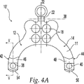
図4A及び4Bに示されるように、付加的な穴パターンが本発明の後頭プレートとともに使用されてもよい。例えば、図4A中、後頭プレート10’はライン32に隣接して配置される四つの穴18を含み、その結果、プレートは穴18に沿って曲がらないでライン32に沿って曲げられてもよい。加えて、これは穴18中に挿入された骨ねじがプレートの中央ライン32に向かって傾斜されることを可能にする。図4B中、後頭プレート10”は穴18の三角形整列を含み、一つの穴がライン28’に沿っており、別の穴がライン30’に沿っている。
Additional hole patterns may be used with the occipital plate of the present invention, as shown in FIGS. 4A and 4B. For example, in FIG. 4A, the
特に図5−6を参照して、後頭プレート10は夫々下部42,44中に穴38,40を含む。穴38,40は記載されるようにクランプポストを受容するような形状と寸法にされる。ロッドを受容するくぼみ46,48は概してV字形であり、“V”の夫々の脚がVノッチ52及び穴40の中央中に延びるライン50に対し角度θ1で延び、更にライン32,34,36に平行に整列される。好ましい実施形態において、角度θ1は約60°〜約80°、更に好ましくは約70°である。弧状段付き(stepped-in)部分54,56がロッドを支持するアーム12,14の最も低い領域に沿って配置され、好ましくはライン50に対し対称的に約80°〜約120°、更に好ましくは約100°の全角度で延びる。図5に示されるように、穴38,40はテーパ付けされることが好ましく、前面11上の第一直径D1は裏面13上の第二直径D2より小さい。
With particular reference to FIGS. 5-6, the
図7を参照して、中央延長部分16は平面60に沿って配置され、一方、ロッドを支持するアーム12,14は平面62に沿って配置される。平面60,62は共平面ではなく、互いに対し角度θ3を形成し、この角度は約160°〜約175°であることが好ましく、約170°であることが更に好ましい。
Referring to FIG. 7, the
図8−10を参照して、ポスト64が示される。一つのポスト64はテーパ付きヘッド66が穴中にあるように夫々の穴38,40中に入れられる。テーパ付きヘッド66はポスト64の中心軸線70に対し約5°〜15°、更に好ましくは約10°の角度θ4でテーパ付けすることが好ましく、このテーパ角度はまた穴38,40にも存在する。穴38中に設置されたポスト64が図9−10に示される。ヘッド66は、穴38,40の内面の鋸歯状突起と相互ロックする鋸歯状突起を備えていることが好ましく、その結果、確実な機械的係合が得られてポスト64を後頭プレート10に対して適所にロックすることを補助し得る。ポスト64はまたボディ部分68を含み、これはナット又はその他の同様のねじ込み締結装置を受容するために少なくとも部分的にねじ込まれることが好ましい。
With reference to FIGS. 8-10, post 64 is shown. One
図11−14を参照して、クランプ組立体24,26の一部としての使用のためのクランププレート72が示される。クランププレート72は長さ方向のロッドとの係合のためのフック付き鋸歯状部分74を含み、更にポスト64が受容される中央旋回穴76を含む。各クランププレート72の脚78は、ロッド支持アーム12,14の弧状段付き部分54,56中に受容される。クランププレート72の前縁80は上縁82に対し角度θ5で配置され、角度θ5は約45°であることが好ましい。裏縁84は後縁86に対し角度θ6で配置され、角度θ6は約38°であることが好ましい。外面88及び内面90の夫々は互いに対し実質的に平行である。縁部92は縁部93に対し角度θ7で配置され、角度θ7は約22°であることが好ましい。
With reference to FIGS. 11-14, a
簡潔に図15−18を参照して、本発明による使用のためのブシュ20が示される。ブシュ20は上面116、下面118、及び側壁120を有する。側壁120は貫通穴18内の多軸回転のための形状と寸法にされた外面122を有する。結果として、また以下に更に詳しく記載されるように、穴124(これはブシュ20の内面126により形成され、上面116及び下面118の両方中に延びる)中に挿入されるファスナは、後頭プレート10に対し多種の方位で挿入し得る。例示の実施形態において、ブシュ20は切頭球形(frustospherical)の形状を有する。また、ブシュ20は円錐台の形状を有し得る。いずれの形状でも、穴124は平行な上面116及び下面118に垂直の中央の長さ方向の軸線を通じて延びることができる。
Briefly referring to FIGS. 15-18, a
ブシュ20は側壁120に配置されたスロット128を含む。スロット128は側壁120が貫通穴18に対し外向きに膨張することを可能にする。この外向きの膨張はブシュ20を貫通穴18の軸線に対し選ばれた方位でロックする。膨張後のロック効果を増進するために、側壁120の外面122及び/又は貫通穴18の周囲が隆起130を備え得る。隆起130は、側壁120が一旦外向きに膨張すると後頭プレート10に対するブシュ20の運動に抵抗する付加的なメカニズムを与える。四つのスロットを有するブシュ20が示されているが、選ばれた数のスロットが側壁120の外向きの膨張を与える限り、1個を含む、あらゆる数のスロットが使用し得る。スロット128aは上面116から下面118中に延び、一方、スロット128の残りは下面118中に延びない。スロット128は全てがブシュ20の上面116から延びる。
The
好ましい実施形態において、本発明による使用に適した予備曲げロッドが図19−21に示される。夫々のロッド140は脊椎に概して平行に走るための真直部分142、曲がり部分144、及び鋸歯状クランプ部分146を含む。部分142,146は互いに対し実質的に垂直であり、一方、部分144,146は互いに対し角度θ8で配置される。角度θ8は約40°〜約50°であることが好ましく、約45°であることが更に好ましい。図21に示されるように、鋸歯状クランプ部分146はその周囲の一部のまわりに鋸歯状突起148を含む。曲がり部分144が垂直ライン150と整列され、部分146が垂直ライン150、152の交点に集中される場合、鋸歯状突起148のみがライン152から角度θ9で延びることが図21からわかる。角度θ9は約30°〜約50°であることが好ましく、約41°であることが更に好ましい。更に、鋸歯状突起148は中心点154から測定して全角度範囲θ10にわたってロッド148の部分146の周囲に沿って存在する。θ10は約90°〜180°であることが好ましく、θ10は約156°であることが更に好ましい。
In a preferred embodiment, a pre-bending rod suitable for use with the present invention is shown in FIGS. 19-21. Each
後頭プレート10とともに使用される対のロッドは典型的には互いの鏡像である。例えば、ロッド140が右のクランプ組立体26とともに使用され、一方、ロッド140の鏡像が、図19Aに示されるように、左のクランプ組立体24とともに使用されるであろう。
The pair of rods used with the
図22−23に示される別の実施形態において、予備曲げロッド160は脊椎に対し概して平行に走るための真直部分162、遷移部分164、及び鋸歯状クランプ部分166を含む。部分162,166は互いに対し実質的に垂直であり、一方、部分164,166は互いに対し角度θ11で配置される。角度θ11は約40°〜約50°であることが好ましく、約45°であることが更に好ましい。
In another embodiment shown in FIGS. 22-23, the
予備曲げロッド140,160は図24中の夫々のクランプ組立体24,26中に保持されて示される。後頭プレート10とともに使用される対のロッドは典型的には互いの鏡像であるが、例示の目的のためのみに、夫々のロッド140,160の一つが示される。特にクランプ組立体24について見られるように、クランププレート72がポスト64のまわりに回転し、ナット168を使用して適所に固定されてもよい。ロッドを受容するくぼみ46,48が使用されてロッド140,160を適所に更にロックする。
後頭プレートの別の実施形態が図25−31に示される。最初に図25−26を参照して、後頭プレート10と同様に、後頭プレート200は骨ファスナを受容するための7個の穴18を含む。しかしながら、この実施形態において、穴18は三つに代えて四つの平行ライン202,204,206,208のまわりに配置される。加えて、特に図26に示されるように、U字形又はC字形部分216中に延びる止めねじ210を使用して、予備曲げロッドが後頭プレート200にクランプされ、これらは領域214中に保持されたロッドの中央と一直線にされてもよく、又はそれからわずかにずれてもよい軸線212のまわりに配置される。別の実施形態が図27−29に示され、この場合、後頭プレート250は四つの平行ライン254,256,258,260のまわりに配置された9個の穴18を備えている。後頭プレート200のように、部分262が脊椎固定ロッドを後頭プレート250にクランプするために用意される。ねじ込み止めねじ(示されていない)が同様のねじ穴264中にねじ込み自在に受容され、これはプレート壁268に対し角度θ12で配置された軸線266に沿って整列されることが好ましい。角度θ12は約50°〜約70°であることが好ましく、約60°であることが更に好ましい。再度、ねじ穴264は止めねじを領域270中にあり、かつ位置272付近に集中されるロッドの中心からずれるように整列させる。
Another embodiment of the occipital plate is shown in FIGS. 25-31. Referring initially to FIGS. 25-26, like the
後頭プレートの付加的な実施形態が図30−31に示される。注目すべきは、プレート穴18中に設置され、又は部分的に設置された膨張ヘッドねじ282が示される。後頭プレート280,300は曲げを促進するためにノッチ付き領域284,302を夫々含む。また、側部クランプ組立体286,304が夫々の穴288,306中に延びる止めねじで固定されるロッド290,308を受容する。側部クランプ組立体286,304はロッド290,308が曲げの前にプレートの平面に対し約20°〜約30°、更に好ましくは約25°の角度で配置されるように傾斜されることが好ましい。
Additional embodiments of the occipital plate are shown in FIGS. 30-31. Of note, an
本発明の幾つかの好ましい実施形態において、3.5mmの直径を有する円筒形ロッドが脊椎ロッド又は予備曲げロッドとして使用される。別の実施形態において、真っ直ぐなロッドが使用されてもよく、従って外科医によりロッドベンダを使用することにより方位決めされてもよい。 In some preferred embodiments of the invention, a cylindrical rod having a diameter of 3.5 mm is used as the spinal rod or pre-bending rod. In another embodiment, a straight rod may be used and thus oriented by the surgeon using a rod bender.
本明細書に開示された後頭プレートデザインにおいて、ねじ穴は後頭の中心線における使用のためにプレートの中心線に沿って配置された。何とならば、そこでの骨厚さは側部より大きいからである。幾つかの実施形態において、ねじ穴は約12°傾斜されてねじ回しによるねじへの接近を促進し、そしてくさび効果のためにねじの引抜き強さを増進し得る。膨張ヘッドねじが好ましいが、その他の非ロックねじが使用されてもよい。夫々のプレートのクランプ組立体又は装置の間のアーク形カットが骨移植片の配置を可能にする。好ましい実施形態において、後頭プレート10はチタンから形成される。後頭プレートの形状はその多軸曲げを促進することが好ましい。
In the occipital plate design disclosed herein, the screw holes were positioned along the plate centerline for use at the occipital centerline. Because the bone thickness there is larger than the side. In some embodiments, the screw holes can be tilted about 12 ° to facilitate access to the screw by a screwdriver and to enhance the pull-out strength of the screw due to the wedge effect. An expansion head screw is preferred, but other non-locking screws may be used. Arc-shaped cuts between the clamp assemblies or devices on each plate allow for the placement of bone grafts. In a preferred embodiment, the
骨ねじを受容するための本発明の後頭プレート中に用意される穴の数は、穴のパターン及び相対的アライメントと同様に、変化されてもよい。その他のねじ穴形状、例えば、卵形、及びその他の穴サイズだけでなく、ねじをロックするための別の手段が使用されてもよい。ブシュは幾つかの実施形態では含まれなくてもよい。後頭プレートを骨に取り付けるための別のファスナとして、ステープル及びワイヤが挙げられる。 The number of holes provided in the occipital plate of the present invention for receiving bone screws may vary as well as the hole pattern and relative alignment. Other means for locking the screw may be used as well as other screw hole shapes, such as oval and other hole sizes. Bushings may not be included in some embodiments. Other fasteners for attaching the occipital plate to the bone include staples and wires.
本発明の種々の説明が上記されるが、種々の特徴が単独で、又はあらゆる組み合わせで使用し得ることが理解されるべきである。それ故、本発明は本明細書に示された特別に好ましい実施形態のみに限定されるべきではない。 While various descriptions of the present invention are described above, it should be understood that various features may be used alone or in any combination. Therefore, the present invention should not be limited only to the particularly preferred embodiments shown herein.
更に、本発明の精神及び範囲内の変化及び改良は本発明が関係する当業者に生じ得ることが理解されるべきである。例えば、後頭プレートの幾つかの実施形態のC字形クランプ部分はその代わりにロッドを受容するための完全円形領域を含んでもよい。別の実施形態において、ロッドを受容するためのスリーブは後頭プレートの長さの一部又は全部を横切って延びてもよい。更に別の実施形態において、二つの一層小さい後頭プレートが後頭への固定のために用意され、夫々のプレートが単一クランプ組立体を有し、一つのロッドを受容する。それ故、本発明の精神及び範囲内である本明細書に示された開示から当業者により容易に達成し得る全ての適当な改良は本発明の更なる実施形態として含まれるべきである。それ故、本発明の範囲は特許請求の範囲に示されたように特定される。 Furthermore, it should be understood that variations and modifications within the spirit and scope of the invention may occur to those skilled in the art to which the invention pertains. For example, the C-shaped clamp portion of some embodiments of the occipital plate may instead include a fully circular region for receiving the rod. In another embodiment, the sleeve for receiving the rod may extend across part or all of the length of the occipital plate. In yet another embodiment, two smaller occipital plates are provided for occipital fixation, each plate having a single clamp assembly and receiving one rod. It is therefore to be understood that all suitable modifications, which can be readily accomplished by those skilled in the art from the disclosure provided herein, that are within the spirit and scope of the invention, should be included as further embodiments of the invention. Therefore, the scope of the present invention is specified as shown in the claims.
Claims (22)
前記プレート(10)が後頭部に合致するように曲げ可能であり、The plate (10) is bendable to match the back of the head;
A)前記プレート(10)がY字形であり、A) The plate (10) is Y-shaped,
B)前記骨ねじ穴(18)の少なくとも一つが、導入されるねじの多軸的定位を可能にするブッシュ(20)を備えることを特徴とする後頭部プレート(10)。B) The occipital plate (10), characterized in that at least one of the bone screw holes (18) is provided with a bushing (20) that allows multiaxial localization of the introduced screw.
Applications Claiming Priority (2)
| Application Number | Priority Date | Filing Date | Title |
|---|---|---|---|
| US09/788,639 US6902565B2 (en) | 2001-02-21 | 2001-02-21 | Occipital plate and system for spinal stabilization |
| PCT/US2002/005308 WO2002067791A2 (en) | 2001-02-21 | 2002-02-19 | Occipital plate and system for spinal stabilization |
Publications (3)
| Publication Number | Publication Date |
|---|---|
| JP2004523299A JP2004523299A (en) | 2004-08-05 |
| JP2004523299A5 JP2004523299A5 (en) | 2005-12-22 |
| JP4202143B2 true JP4202143B2 (en) | 2008-12-24 |
Family
ID=25145102
Family Applications (1)
| Application Number | Title | Priority Date | Filing Date |
|---|---|---|---|
| JP2002567166A Expired - Lifetime JP4202143B2 (en) | 2001-02-21 | 2002-02-19 | System for occipital plate and spine stabilization |
Country Status (16)
| Country | Link |
|---|---|
| US (2) | US6902565B2 (en) |
| EP (1) | EP1372501B1 (en) |
| JP (1) | JP4202143B2 (en) |
| AR (1) | AR033864A1 (en) |
| AT (1) | ATE284648T1 (en) |
| AU (1) | AU2002247190B2 (en) |
| BR (1) | BR0207472A (en) |
| CA (1) | CA2438861C (en) |
| DE (1) | DE60202267T2 (en) |
| DK (1) | DK1372501T3 (en) |
| ES (1) | ES2231678T3 (en) |
| HK (1) | HK1061339A1 (en) |
| MX (1) | MXPA03007509A (en) |
| NZ (1) | NZ527250A (en) |
| PT (1) | PT1372501E (en) |
| WO (1) | WO2002067791A2 (en) |
Families Citing this family (133)
| Publication number | Priority date | Publication date | Assignee | Title |
|---|---|---|---|---|
| US6599290B2 (en) | 2001-04-17 | 2003-07-29 | Ebi, L.P. | Anterior cervical plating system and associated method |
| EP1427341A1 (en) | 2001-07-20 | 2004-06-16 | Spinal Concepts Inc. | Spinal stabilization system and method |
| US6755833B1 (en) | 2001-12-14 | 2004-06-29 | Kamaljit S. Paul | Bone support assembly |
| US7070599B2 (en) | 2002-07-24 | 2006-07-04 | Paul Kamaljit S | Bone support assembly |
| US7232441B2 (en) * | 2002-02-13 | 2007-06-19 | Cross Medicalproducts, Inc. | Occipital plate and rod system |
| US20040153338A1 (en) * | 2002-05-08 | 2004-08-05 | Back Kim | Medical information system |
| US7001389B1 (en) | 2002-07-05 | 2006-02-21 | Navarro Richard R | Fixed and variable locking fixation assembly |
| US7575588B2 (en) * | 2003-02-03 | 2009-08-18 | Warsaw Orthopedic Inc. | Midline occipital vertebral fixation system |
| US8172885B2 (en) | 2003-02-05 | 2012-05-08 | Pioneer Surgical Technology, Inc. | Bone plate system |
| JP4346358B2 (en) * | 2003-06-20 | 2009-10-21 | Necエレクトロニクス株式会社 | Chemically amplified resist composition, semiconductor device manufacturing method using the same, and pattern forming method |
| US8167917B2 (en) * | 2003-09-24 | 2012-05-01 | Spinefrontier Lls | Apparatus and method for spine fixation |
| US8900277B2 (en) | 2004-02-26 | 2014-12-02 | Pioneer Surgical Technology, Inc. | Bone plate system |
| US7740649B2 (en) | 2004-02-26 | 2010-06-22 | Pioneer Surgical Technology, Inc. | Bone plate system and methods |
| US7942913B2 (en) | 2004-04-08 | 2011-05-17 | Ebi, Llc | Bone fixation device |
| US7942912B2 (en) * | 2004-05-25 | 2011-05-17 | University Of Utah Research Foundation | Occipitocervical plate |
| US8241337B2 (en) * | 2004-05-25 | 2012-08-14 | Brockmeyer Douglas L | Occipitocervical plate |
| WO2005122922A2 (en) * | 2004-06-14 | 2005-12-29 | Abdou M S | Occipital fixation system and method of use |
| US20060082015A1 (en) * | 2004-09-30 | 2006-04-20 | Inion Ltd. | Surgical implant shaping instrument, surgical system and method |
| EP1814474B1 (en) | 2004-11-24 | 2011-09-14 | Samy Abdou | Devices for inter-vertebral orthopedic device placement |
| US7527640B2 (en) | 2004-12-22 | 2009-05-05 | Ebi, Llc | Bone fixation system |
| US7621942B2 (en) | 2005-03-21 | 2009-11-24 | Zimmer Spine, Inc. | Variable geometry occipital fixation plate |
| US20060229611A1 (en) * | 2005-03-30 | 2006-10-12 | Sdgi Holdings, Inc. | Spinal rod connector |
| US7931681B2 (en) * | 2005-04-14 | 2011-04-26 | Warsaw Orthopedic, Inc. | Anti-backout mechanism for an implant fastener |
| WO2006116606A2 (en) | 2005-04-27 | 2006-11-02 | James Marino | Mono-planar pedilcle screw method, system, and kit |
| US7824433B2 (en) | 2005-05-03 | 2010-11-02 | Williams Lytton A | Bone anchored surgical mesh |
| US8177818B2 (en) | 2005-09-08 | 2012-05-15 | Securos, Inc. | Fixation plate |
| US7955364B2 (en) * | 2005-09-21 | 2011-06-07 | Ebi, Llc | Variable angle bone fixation assembly |
| ES2436101T3 (en) * | 2005-10-07 | 2013-12-27 | Alphatec Spine, Inc. | Adjustable occipital plate |
| CA2626145A1 (en) * | 2005-10-25 | 2007-05-03 | Anthem Orthopaedics Llc | Bone fastening assembly and bushing and screw for use therewith |
| US8100952B2 (en) * | 2005-12-22 | 2012-01-24 | Anthem Orthopaedics Llc | Drug delivering bone plate and method and targeting device for use therewith |
| US7695500B2 (en) * | 2006-03-10 | 2010-04-13 | Custom Spine, Inc. | Polyaxial occipital plate |
| US20070299441A1 (en) * | 2006-06-09 | 2007-12-27 | Zachary M. Hoffman | Adjustable Occipital Plate |
| US7776070B2 (en) * | 2006-08-02 | 2010-08-17 | Warsaw Orthopedic, Inc. | Occipital plating systems and methods |
| US7901433B2 (en) * | 2006-10-04 | 2011-03-08 | Zimmer Spine, Inc. | Occipito-cervical stabilization system and method |
| US20080091186A1 (en) * | 2006-10-13 | 2008-04-17 | Tyco Electronics Corporation | Electro-surgical device RF energy needle electrical shorting plate |
| US8147527B2 (en) | 2006-11-28 | 2012-04-03 | Zimmer Spine, Inc. | Adjustable occipital plate |
| US20080147123A1 (en) * | 2006-12-14 | 2008-06-19 | Seaspine, Inc. | Occipital plate assembly |
| US8246662B2 (en) * | 2006-12-27 | 2012-08-21 | Zimmer Spine, Inc. | Modular occipital plate |
| US8636737B2 (en) | 2006-12-27 | 2014-01-28 | Zimmer Spine, Inc. | Modular occipital plate |
| US7931676B2 (en) * | 2007-01-18 | 2011-04-26 | Warsaw Orthopedic, Inc. | Vertebral stabilizer |
| US8556939B2 (en) * | 2008-01-08 | 2013-10-15 | Fraser Cummins Henderson | Mathematical relationship of strain, neurological dysfunction and abnormal behavior resulting from neurological dysfunction of the brainstem |
| US9827023B2 (en) | 2007-01-29 | 2017-11-28 | Life Spine, Inc. | Craniospinal fusion method and apparatus |
| US8043342B2 (en) | 2007-01-29 | 2011-10-25 | Polaris Biotechnology, Inc. | Craniospinal fusion method and apparatus |
| US20090036894A1 (en) * | 2007-01-29 | 2009-02-05 | Polaris Biotechnology, Inc. | Method of treating a neurological condition through correction and stabilization of the clivo-axial angle |
| US8403965B2 (en) * | 2007-01-29 | 2013-03-26 | Polaris Biotechnology, Inc. | Vertebra attachment method and system |
| US8182511B2 (en) * | 2007-01-29 | 2012-05-22 | Polaris Biotechnology, Inc. | Craniospinal fusion method and apparatus |
| US20080234742A1 (en) * | 2007-03-08 | 2008-09-25 | Cascarino Jose Ludovico | Head Fixation Device |
| US9072548B2 (en) * | 2007-06-07 | 2015-07-07 | Anthem Orthopaedics Llc | Spine repair assembly |
| US8361126B2 (en) | 2007-07-03 | 2013-01-29 | Pioneer Surgical Technology, Inc. | Bone plate system |
| US8623019B2 (en) | 2007-07-03 | 2014-01-07 | Pioneer Surgical Technology, Inc. | Bone plate system |
| WO2009055747A1 (en) | 2007-10-24 | 2009-04-30 | Nuvasive, Inc. | Surgical fixation system and related methods |
| US20090125067A1 (en) * | 2007-11-08 | 2009-05-14 | Depuy Spine, Inc. | In-line occipital plate and method of use |
| WO2009073614A2 (en) * | 2007-11-29 | 2009-06-11 | University Of South Florida | Apparatus for occipito-cervical fixation enabling supplemental occipital bone fixation |
| US8317842B2 (en) * | 2007-11-30 | 2012-11-27 | Biomet C.V. | Distal tibia plating system |
| WO2009089395A2 (en) * | 2008-01-08 | 2009-07-16 | Polaris Biotechnology, Inc. | Osteointegration apparatus |
| US8088163B1 (en) | 2008-02-06 | 2012-01-03 | Kleiner Jeffrey B | Tools and methods for spinal fusion |
| US9060813B1 (en) | 2008-02-29 | 2015-06-23 | Nuvasive, Inc. | Surgical fixation system and related methods |
| US8551144B2 (en) * | 2008-04-22 | 2013-10-08 | Collab Comlo, LLC | Bone plate system configurable as static or dynamic implant |
| US8672944B2 (en) * | 2008-06-27 | 2014-03-18 | K2M, Inc. | System and method for performing spinal surgery |
| US20100057141A1 (en) * | 2008-08-27 | 2010-03-04 | Custom Spine, Inc. | Multi-anchor anti-back out mechanism and method |
| USD853560S1 (en) | 2008-10-09 | 2019-07-09 | Nuvasive, Inc. | Spinal implant insertion device |
| US8226695B2 (en) | 2008-10-10 | 2012-07-24 | K2M, Inc. | Occipital plate for cervical fixation |
| US8187277B2 (en) * | 2008-11-17 | 2012-05-29 | Warsaw Orthopedic, Inc. | Translational occipital vertebral fixation system |
| US9717403B2 (en) | 2008-12-05 | 2017-08-01 | Jeffrey B. Kleiner | Method and apparatus for performing retro peritoneal dissection |
| US8864654B2 (en) | 2010-04-20 | 2014-10-21 | Jeffrey B. Kleiner | Method and apparatus for performing retro peritoneal dissection |
| US8366748B2 (en) | 2008-12-05 | 2013-02-05 | Kleiner Jeffrey | Apparatus and method of spinal implant and fusion |
| IT1392298B1 (en) | 2008-12-17 | 2012-02-24 | N B R New Biotechnology Res | MODULAR VERTEBRAL STABILIZER. |
| US8506567B2 (en) | 2009-02-04 | 2013-08-13 | Lanx, Inc. | Occipital plate fixation system |
| US9247943B1 (en) | 2009-02-06 | 2016-02-02 | Kleiner Intellectual Property, Llc | Devices and methods for preparing an intervertebral workspace |
| USD656610S1 (en) | 2009-02-06 | 2012-03-27 | Kleiner Jeffrey B | Spinal distraction instrument |
| US20100222825A1 (en) * | 2009-03-02 | 2010-09-02 | Warsaw Orthopedic, Inc. | Side-loading occipital vertebral fixation system |
| US20100256687A1 (en) | 2009-04-01 | 2010-10-07 | Merete Medical Gmbh | Fixation Device and Method of Use for a Ludloff Osteotomy Procedure |
| DE102009016394B4 (en) | 2009-04-07 | 2016-02-11 | Merete Medical Gmbh | Device for stable-angle fixation and compression of a fracture site or osteotomy on a bone |
| US8348981B2 (en) * | 2009-06-23 | 2013-01-08 | Aesculap Implany Systems, LLC | Minimal access occipital plate |
| US9011500B2 (en) * | 2009-07-29 | 2015-04-21 | Globus Medical, Inc. | Clivus plate |
| US8685031B2 (en) | 2009-09-18 | 2014-04-01 | Spinal Surgical Strategies, Llc | Bone graft delivery system |
| US20170238984A1 (en) | 2009-09-18 | 2017-08-24 | Spinal Surgical Strategies, Llc | Bone graft delivery device with positioning handle |
| US9173694B2 (en) | 2009-09-18 | 2015-11-03 | Spinal Surgical Strategies, Llc | Fusion cage with combined biological delivery system |
| US10245159B1 (en) | 2009-09-18 | 2019-04-02 | Spinal Surgical Strategies, Llc | Bone graft delivery system and method for using same |
| USD750249S1 (en) | 2014-10-20 | 2016-02-23 | Spinal Surgical Strategies, Llc | Expandable fusion cage |
| US9186193B2 (en) | 2009-09-18 | 2015-11-17 | Spinal Surgical Strategies, Llc | Fusion cage with combined biological delivery system |
| US9060877B2 (en) | 2009-09-18 | 2015-06-23 | Spinal Surgical Strategies, Llc | Fusion cage with combined biological delivery system |
| US10973656B2 (en) | 2009-09-18 | 2021-04-13 | Spinal Surgical Strategies, Inc. | Bone graft delivery system and method for using same |
| USD723682S1 (en) | 2013-05-03 | 2015-03-03 | Spinal Surgical Strategies, Llc | Bone graft delivery tool |
| US8906028B2 (en) | 2009-09-18 | 2014-12-09 | Spinal Surgical Strategies, Llc | Bone graft delivery device and method of using the same |
| US9629729B2 (en) | 2009-09-18 | 2017-04-25 | Spinal Surgical Strategies, Llc | Biological delivery system with adaptable fusion cage interface |
| US20110106085A1 (en) * | 2009-10-30 | 2011-05-05 | Warsaw Orthopedic, Inc. | Adjustable occipital vertebral fixation system |
| WO2011053962A1 (en) * | 2009-11-02 | 2011-05-05 | Life Spine, Inc. | Laminoplasty rod system |
| US8764806B2 (en) | 2009-12-07 | 2014-07-01 | Samy Abdou | Devices and methods for minimally invasive spinal stabilization and instrumentation |
| TWI397394B (en) * | 2009-12-21 | 2013-06-01 | Ind Tech Res Inst | Flexible spine fixing structure |
| ES2573811T3 (en) | 2009-12-22 | 2016-06-10 | Merete Medical Gmbh | Bone plaque system for osteosynthesis |
| TWI388308B (en) * | 2009-12-31 | 2013-03-11 | Ind Tech Res Inst | Flexible spine fixing structure |
| US8702758B2 (en) | 2009-12-31 | 2014-04-22 | Industrial Technology Research Institute | Flexible spine fixing structure |
| US8986351B2 (en) * | 2010-01-26 | 2015-03-24 | Pioneer Surgical Technology, Inc. | Occipital plate for spinal fusion |
| US9381044B2 (en) | 2010-01-26 | 2016-07-05 | Pioneer Surgical Technology, Inc. | Posterior spinal stabilization plate device |
| US8647369B2 (en) | 2010-05-19 | 2014-02-11 | Josef E. Gorek | Minimal profile anterior bracket for spinal fixation |
| CN103025256B (en) * | 2010-07-21 | 2016-07-20 | 斯恩蒂斯有限公司 | Device for osteorrhaphy |
| US8518042B2 (en) * | 2010-10-19 | 2013-08-27 | Biomet Manufacturing, Llc | Orthopedic plate assembly for a distal radius having re-contouring features and method for using same |
| US9387013B1 (en) | 2011-03-01 | 2016-07-12 | Nuvasive, Inc. | Posterior cervical fixation system |
| US8992579B1 (en) | 2011-03-08 | 2015-03-31 | Nuvasive, Inc. | Lateral fixation constructs and related methods |
| US9480510B2 (en) | 2011-03-23 | 2016-11-01 | Spinecraft, LLC | Devices, systems and methods of attaching same to the spine |
| DE202011051165U1 (en) | 2011-08-31 | 2011-11-14 | Merete Medical Gmbh | Anatomically adapted, plantar bone plate and bone plate system |
| US8845728B1 (en) | 2011-09-23 | 2014-09-30 | Samy Abdou | Spinal fixation devices and methods of use |
| US9216042B2 (en) * | 2011-12-09 | 2015-12-22 | Pioneer Surgical Technology, Inc. | Adjustable fixation device |
| US20130226240A1 (en) | 2012-02-22 | 2013-08-29 | Samy Abdou | Spinous process fixation devices and methods of use |
| US9060815B1 (en) | 2012-03-08 | 2015-06-23 | Nuvasive, Inc. | Systems and methods for performing spine surgery |
| US9566094B2 (en) | 2012-03-12 | 2017-02-14 | Globus Medical, Inc. | Occipital plate systems |
| US20130253516A1 (en) * | 2012-03-23 | 2013-09-26 | John L Mackall | Occipital plate |
| DE102012103894B4 (en) | 2012-05-03 | 2016-10-27 | Merete Medical Gmbh | Bone plate system for osteosynthesis |
| US9510866B2 (en) * | 2012-08-15 | 2016-12-06 | Blackstone Medical, Inc. | Pivoting spinal fixation devices |
| US9198767B2 (en) | 2012-08-28 | 2015-12-01 | Samy Abdou | Devices and methods for spinal stabilization and instrumentation |
| US9320617B2 (en) | 2012-10-22 | 2016-04-26 | Cogent Spine, LLC | Devices and methods for spinal stabilization and instrumentation |
| AU2014212444B2 (en) | 2013-01-29 | 2017-05-18 | Chester Evan Sutterlin | Occipital plate assemblies with polyaxial head connectors |
| US9545276B2 (en) | 2013-03-15 | 2017-01-17 | Aristotech Industries Gmbh | Fixation device and method of use for a lapidus-type plantar hallux valgus procedure |
| JP2014200430A (en) * | 2013-04-04 | 2014-10-27 | 康寛 斉宮 | Orthodontic implant jig |
| US9517089B1 (en) | 2013-10-08 | 2016-12-13 | Nuvasive, Inc. | Bone anchor with offset rod connector |
| US11197703B2 (en) * | 2013-12-20 | 2021-12-14 | Kelyniam Global, Inc. | Fixation article for an implant |
| USD745162S1 (en) | 2014-01-27 | 2015-12-08 | Merete Medical Gmbh | Bone plate |
| US10857003B1 (en) | 2015-10-14 | 2020-12-08 | Samy Abdou | Devices and methods for vertebral stabilization |
| USD797290S1 (en) | 2015-10-19 | 2017-09-12 | Spinal Surgical Strategies, Llc | Bone graft delivery tool |
| ITUB20155792A1 (en) * | 2015-11-20 | 2017-05-20 | Medacta Int Sa | OCCIPITAL PLATE FOR STATIONARY-CERVICAL FIXING AND SYSTEM FOR STATIONARY-CERVICAL FIXING |
| WO2017127647A1 (en) * | 2016-01-22 | 2017-07-27 | Spinal Usa, Inc. | Spinal fixation systems and methods |
| RU2615900C1 (en) * | 2016-04-26 | 2017-04-11 | Алексей Николаевич Шкарубо | Device for c1-c2 vertebrae front stabilization |
| US10744000B1 (en) | 2016-10-25 | 2020-08-18 | Samy Abdou | Devices and methods for vertebral bone realignment |
| US10973648B1 (en) | 2016-10-25 | 2021-04-13 | Samy Abdou | Devices and methods for vertebral bone realignment |
| CN107822747B (en) * | 2017-09-22 | 2023-07-25 | 牛国旗 | 3D prints pillow neck and fuses fixing device |
| EP3533403B1 (en) | 2018-03-02 | 2022-08-17 | Stryker European Holdings I, LLC | Bone plates and associated screws |
| US11179248B2 (en) | 2018-10-02 | 2021-11-23 | Samy Abdou | Devices and methods for spinal implantation |
| US11298244B2 (en) | 2019-01-31 | 2022-04-12 | K2M, Inc. | Interbody implants and instrumentation |
| US11534307B2 (en) | 2019-09-16 | 2022-12-27 | K2M, Inc. | 3D printed cervical standalone implant |
| US11877779B2 (en) | 2020-03-26 | 2024-01-23 | Xtant Medical Holdings, Inc. | Bone plate system |
| US11364055B2 (en) | 2020-09-02 | 2022-06-21 | Zavation, Llc | Occipital plate and hinged rod assembly |
| US11950811B2 (en) | 2020-09-22 | 2024-04-09 | Alphatec Spine, Inc. | Occipital plates and related methods |
Family Cites Families (74)
| Publication number | Priority date | Publication date | Assignee | Title |
|---|---|---|---|---|
| US3242922A (en) | 1963-06-25 | 1966-03-29 | Charles B Thomas | Internal spinal fixation means |
| US4289123A (en) | 1980-03-31 | 1981-09-15 | Dunn Harold K | Orthopedic appliance |
| DE3121272A1 (en) * | 1981-05-29 | 1982-12-23 | Ulrich, Max Bernhard, 7900 Ulm | CORRECTIONAL IMPLANT FOR LUMBOSACRAL SPONDYLODESIS |
| ES272906Y (en) | 1981-06-18 | 1984-12-16 | Mecron Medizinische Produkte Gmbh | NAIL DEVICE FOR FIXING A FEMUR FRACTURE. |
| US4454876A (en) | 1982-05-25 | 1984-06-19 | University Of Pittsburgh | Pelvic fixation plate and method of implanting same |
| US4604995A (en) | 1984-03-30 | 1986-08-12 | Stephens David C | Spinal stabilizer |
| US4773402A (en) * | 1985-09-13 | 1988-09-27 | Isola Implants, Inc. | Dorsal transacral surgical implant |
| GB8626409D0 (en) | 1986-11-05 | 1986-12-03 | Showell A W Sugicraft Ltd | Spinal etc fixation devices |
| US5007909A (en) | 1986-11-05 | 1991-04-16 | Chaim Rogozinski | Apparatus for internally fixing the spine |
| DE8706912U1 (en) | 1987-05-14 | 1987-08-27 | Howmedica GmbH, 2314 Schönkirchen | Small bone plate and screws, particularly for the treatment of fractures of the skull and facial skeleton or similar. |
| US4887595A (en) | 1987-07-29 | 1989-12-19 | Acromed Corporation | Surgically implantable device for spinal columns |
| GB8721661D0 (en) | 1987-09-15 | 1987-10-21 | Showell A W Sugicraft Ltd | Spinal/skull fixation device |
| GB8825909D0 (en) | 1988-11-04 | 1988-12-07 | Showell A W Sugicraft Ltd | Pedicle engaging means |
| FR2658413B1 (en) | 1990-02-19 | 1997-01-03 | Sofamor | OSTEOSYNTHESIS DEVICE FOR THE CORRECTION OF SPINAL DEVIATIONS. |
| US5030220A (en) | 1990-03-29 | 1991-07-09 | Advanced Spine Fixation Systems Incorporated | Spine fixation system |
| WO1991016020A1 (en) | 1990-04-26 | 1991-10-31 | Danninger Medical Technology, Inc. | Transpedicular screw system and method of use |
| US5092893A (en) | 1990-09-04 | 1992-03-03 | Smith Thomas E | Human orthopedic vertebra implant |
| US5300073A (en) | 1990-10-05 | 1994-04-05 | Salut, Ltd. | Sacral implant system |
| US5127912A (en) | 1990-10-05 | 1992-07-07 | R. Charles Ray | Sacral implant system |
| US5113685A (en) | 1991-01-28 | 1992-05-19 | Acromed Corporation | Apparatus for contouring spine plates and/or rods |
| US5603713A (en) | 1991-09-24 | 1997-02-18 | Aust; Gilbert M. | Anterior lumbar/cervical bicortical compression plate |
| GB9122753D0 (en) | 1991-10-26 | 1991-12-11 | Reis Nicolas D | Internal ilio-lumbar fixator |
| US5360429A (en) | 1992-02-20 | 1994-11-01 | Jbs Societe Anonyme | Device for straightening, fixing, compressing, and elongating cervical vertebrae |
| FR2689750B1 (en) * | 1992-04-10 | 1997-01-31 | Eurosurgical | BONE ANCHORING ELEMENT AND SPINAL OSTEOSYNTHESIS DEVICE INCORPORATING SUCH ELEMENTS. |
| US5545165A (en) | 1992-10-09 | 1996-08-13 | Biedermann Motech Gmbh | Anchoring member |
| US5702395A (en) | 1992-11-10 | 1997-12-30 | Sofamor S.N.C. | Spine osteosynthesis instrumentation for an anterior approach |
| EP1149560A3 (en) | 1992-11-12 | 2002-03-06 | ALLEYNE, Neville | Spinal protection device |
| US5545164A (en) | 1992-12-28 | 1996-08-13 | Advanced Spine Fixation Systems, Incorporated | Occipital clamp assembly for cervical spine rod fixation |
| CA2103200A1 (en) * | 1992-12-28 | 1994-06-29 | Robert S. Howland | Cervical spine rod fixation system |
| US5947965A (en) | 1992-12-31 | 1999-09-07 | Bryan; Donald W. | Spinal fixation apparatus and method |
| US5306275A (en) | 1992-12-31 | 1994-04-26 | Bryan Donald W | Lumbar spine fixation apparatus and method |
| US5330473A (en) * | 1993-03-04 | 1994-07-19 | Advanced Spine Fixation Systems, Inc. | Branch connector for spinal fixation systems |
| US5415661A (en) | 1993-03-24 | 1995-05-16 | University Of Miami | Implantable spinal assist device |
| WO1994028813A1 (en) | 1993-06-11 | 1994-12-22 | Hillway Surgical Limited | Surgical implant |
| US5558674A (en) | 1993-12-17 | 1996-09-24 | Smith & Nephew Richards, Inc. | Devices and methods for posterior spinal fixation |
| US5476463A (en) | 1994-01-12 | 1995-12-19 | Acromed Corporation | Spinal column retaining apparatus |
| US5507745A (en) | 1994-02-18 | 1996-04-16 | Sofamor, S.N.C. | Occipito-cervical osteosynthesis instrumentation |
| US5601552A (en) * | 1994-03-18 | 1997-02-11 | Sofamor, S.N.C. | Fixing device for a rigid transverse connection device between rods of a spinal osteosynthesis system |
| US5542946A (en) | 1994-05-27 | 1996-08-06 | Sofamor S.N.C. | Hook for an occipito-cervical rod or plate of an occipito-cervical osteosynthesis instrumentation |
| US5527312A (en) | 1994-08-19 | 1996-06-18 | Salut, Ltd. | Facet screw anchor |
| DE4434574A1 (en) | 1994-09-28 | 1996-04-04 | Ulrich Heinrich | Implant for spinal correction |
| FR2729556B1 (en) | 1995-01-23 | 1998-10-16 | Sofamor | SPINAL OSTEOSYNTHESIS DEVICE WITH MEDIAN HOOK AND VERTEBRAL ANCHOR SUPPORT |
| US5620443A (en) | 1995-01-25 | 1997-04-15 | Danek Medical, Inc. | Anterior screw-rod connector |
| US5709686A (en) | 1995-03-27 | 1998-01-20 | Synthes (U.S.A.) | Bone plate |
| FR2732888B1 (en) | 1995-04-11 | 1997-09-05 | Biomat | OSTEOSYNTHESIS DEVICE FOR CONSOLIDATION OF THE CERVICAL RACHIS |
| US5582612A (en) | 1995-05-01 | 1996-12-10 | Lin; Chih-I | Vertebral fixing and retrieving device having centrally two fixation |
| US5630816A (en) | 1995-05-01 | 1997-05-20 | Kambin; Parviz | Double barrel spinal fixation system and method |
| US5947966A (en) | 1995-06-06 | 1999-09-07 | Sdgi Holdings, Inc. | Device for linking adjacent rods in spinal instrumentation |
| DE69630317T2 (en) | 1995-06-06 | 2004-08-05 | SDGI Holding, Inc., Wilmington | DEVICE FOR CONNECTING NEIGHBORING SPINE SUPPORT BARS |
| US5693053A (en) | 1995-10-19 | 1997-12-02 | Sdgi Holdings, Inc. | Variable angle and transitional linking member |
| DE59508984D1 (en) | 1995-11-30 | 2001-02-22 | Synthes Ag | DEVICE FOR BONE FIXATION |
| WO1997023170A1 (en) | 1995-12-22 | 1997-07-03 | Ohio Medical Instrument Company, Inc. | Spinal fixation device with laterally attachable connectors |
| US5885284A (en) | 1996-07-11 | 1999-03-23 | Third Millennium Engineering, L.L.C. | Hinged variable length cross-link device |
| US5810815A (en) | 1996-09-20 | 1998-09-22 | Morales; Jose A. | Surgical apparatus for use in the treatment of spinal deformities |
| US6171311B1 (en) | 1996-10-18 | 2001-01-09 | Marc Richelsoph | Transverse connector |
| EP0934026B1 (en) * | 1996-10-24 | 2009-07-15 | Zimmer Spine Austin, Inc | Apparatus for spinal fixation |
| WO1998041160A1 (en) | 1997-03-17 | 1998-09-24 | Intellect Medical Limited | Cervical fixation system |
| DE29712285U1 (en) | 1997-07-11 | 1997-09-25 | ENDOTEC Vertriebs- und Beratungsgesellschaft für Medizintechnik mbH, 51399 Burscheid | Fixation plate |
| US5891145A (en) * | 1997-07-14 | 1999-04-06 | Sdgi Holdings, Inc. | Multi-axial screw |
| US5954722A (en) * | 1997-07-29 | 1999-09-21 | Depuy Acromed, Inc. | Polyaxial locking plate |
| US6030389A (en) | 1997-08-04 | 2000-02-29 | Spinal Concepts, Inc. | System and method for stabilizing the human spine with a bone plate |
| US5976135A (en) | 1997-12-18 | 1999-11-02 | Sdgi Holdings, Inc. | Lateral connector assembly |
| US5980523A (en) | 1998-01-08 | 1999-11-09 | Jackson; Roger | Transverse connectors for spinal rods |
| US6179838B1 (en) | 1998-02-24 | 2001-01-30 | Daniel Fiz | Bone fixation arrangements and method |
| TW415228U (en) | 1998-04-29 | 2000-12-11 | Nat Science Council | Internal fixer for front position of the spine |
| US5989251A (en) | 1998-06-17 | 1999-11-23 | Surgical Dynamics, Inc. | Apparatus for spinal stabilization |
| ES2260927T3 (en) | 1998-09-11 | 2006-11-01 | Synthes Ag Chur | VERTEBRAL ANGLE VARIABLE FIXING SYSTEM. |
| US6110173A (en) | 1998-09-15 | 2000-08-29 | Advanced Spine Fixation Systems, Inc. | Transverse connector for spinal fixation systems |
| US6146382A (en) * | 1998-09-23 | 2000-11-14 | Spinal Concepts, Inc. | Occipito-cervical stabilization system and method |
| US6331179B1 (en) * | 2000-01-06 | 2001-12-18 | Spinal Concepts, Inc. | System and method for stabilizing the human spine with a bone plate |
| US6235033B1 (en) * | 2000-04-19 | 2001-05-22 | Synthes (Usa) | Bone fixation assembly |
| US6524315B1 (en) * | 2000-08-08 | 2003-02-25 | Depuy Acromed, Inc. | Orthopaedic rod/plate locking mechanism |
| US6485491B1 (en) * | 2000-09-15 | 2002-11-26 | Sdgi Holdings, Inc. | Posterior fixation system |
| US6478798B1 (en) * | 2001-05-17 | 2002-11-12 | Robert S. Howland | Spinal fixation apparatus and methods for use |
-
2001
- 2001-02-21 US US09/788,639 patent/US6902565B2/en not_active Expired - Lifetime
-
2002
- 2002-02-19 WO PCT/US2002/005308 patent/WO2002067791A2/en active IP Right Grant
- 2002-02-19 AU AU2002247190A patent/AU2002247190B2/en not_active Ceased
- 2002-02-19 ES ES02714963T patent/ES2231678T3/en not_active Expired - Lifetime
- 2002-02-19 NZ NZ527250A patent/NZ527250A/en unknown
- 2002-02-19 MX MXPA03007509A patent/MXPA03007509A/en unknown
- 2002-02-19 EP EP02714963A patent/EP1372501B1/en not_active Expired - Lifetime
- 2002-02-19 CA CA002438861A patent/CA2438861C/en not_active Expired - Fee Related
- 2002-02-19 PT PT02714963T patent/PT1372501E/en unknown
- 2002-02-19 DE DE60202267T patent/DE60202267T2/en not_active Expired - Lifetime
- 2002-02-19 AT AT02714963T patent/ATE284648T1/en not_active IP Right Cessation
- 2002-02-19 BR BR0207472-9A patent/BR0207472A/en not_active Application Discontinuation
- 2002-02-19 DK DK02714963T patent/DK1372501T3/en active
- 2002-02-19 JP JP2002567166A patent/JP4202143B2/en not_active Expired - Lifetime
- 2002-02-20 AR ARP020100577A patent/AR033864A1/en unknown
-
2004
- 2004-03-10 HK HK04101749A patent/HK1061339A1/en not_active IP Right Cessation
-
2005
- 2005-01-19 US US11/039,676 patent/US20050124994A1/en not_active Abandoned
Also Published As
| Publication number | Publication date |
|---|---|
| BR0207472A (en) | 2004-04-06 |
| NZ527250A (en) | 2005-03-24 |
| CA2438861C (en) | 2009-01-06 |
| WO2002067791A8 (en) | 2003-12-24 |
| CA2438861A1 (en) | 2002-09-06 |
| DK1372501T3 (en) | 2005-01-24 |
| HK1061339A1 (en) | 2004-09-17 |
| DE60202267T2 (en) | 2005-12-08 |
| JP2004523299A (en) | 2004-08-05 |
| WO2002067791A3 (en) | 2003-03-06 |
| DE60202267D1 (en) | 2005-01-20 |
| AR033864A1 (en) | 2004-01-07 |
| EP1372501A2 (en) | 2004-01-02 |
| US20050124994A1 (en) | 2005-06-09 |
| WO2002067791A2 (en) | 2002-09-06 |
| ATE284648T1 (en) | 2005-01-15 |
| PT1372501E (en) | 2005-04-29 |
| EP1372501B1 (en) | 2004-12-15 |
| AU2002247190B2 (en) | 2005-03-10 |
| US20020120268A1 (en) | 2002-08-29 |
| MXPA03007509A (en) | 2004-07-30 |
| ES2231678T3 (en) | 2005-05-16 |
| US6902565B2 (en) | 2005-06-07 |
Similar Documents
| Publication | Publication Date | Title |
|---|---|---|
| JP4202143B2 (en) | System for occipital plate and spine stabilization | |
| AU2002247190A1 (en) | Occipital plate and system for spinal stabilization | |
| JP4861422B2 (en) | Adjustable occipital plate | |
| JP4072432B2 (en) | Spinal joint fixation device | |
| JP3373270B2 (en) | Osteosynthesis plate system | |
| KR100824185B1 (en) | Orthopedic fixation plates having fixation systems for attaching elongated members and method of use | |
| US7575588B2 (en) | Midline occipital vertebral fixation system | |
| JP4288074B2 (en) | Spinal cord alignment apparatus and method | |
| AU680209B2 (en) | Spinal rod transverse connector for supporting vertebral fixation elements | |
| US20180070990A1 (en) | Spinal osteosynthesis device and preparation method | |
| CA2199866C (en) | Osteosynthesis apparatus | |
| JP4546687B2 (en) | Spinal rod fixation device | |
| JP4885953B2 (en) | Osteosynthesis plate with through holes inclined relative to the plane of the plate | |
| US20010029375A1 (en) | Methods and apparatus for fusionless treatment of spinal deformities | |
| JP2004508130A (en) | Rear fixation system | |
| JPH08252264A (en) | Bone bond device of vertebral column | |
| JPH08509396A (en) | Top clamping clamp for vertebral fixation devices | |
| JPH10503114A (en) | Clamp jaws for spinal fixation devices | |
| JP4185251B2 (en) | Transformer connector for spinal rod coupling | |
| JP2011500276A (en) | Apparatus and method for connecting spinal fixation systems to each other | |
| TW201210563A (en) | Bone plate for the stabilization of bones, device, and method | |
| JPH0998984A (en) | Device for bone joining for adhesion of neck vertebral column | |
| AU2002318541B2 (en) | Spinal osteosynthesis device and preparation method | |
| AU2002318541A1 (en) | Spinal osteosynthesis device and preparation method |
Legal Events
| Date | Code | Title | Description |
|---|---|---|---|
| A521 | Request for written amendment filed |
Free format text: JAPANESE INTERMEDIATE CODE: A523 Effective date: 20050208 |
|
| A621 | Written request for application examination |
Free format text: JAPANESE INTERMEDIATE CODE: A621 Effective date: 20050208 |
|
| A711 | Notification of change in applicant |
Free format text: JAPANESE INTERMEDIATE CODE: A711 Effective date: 20061219 |
|
| RD02 | Notification of acceptance of power of attorney |
Free format text: JAPANESE INTERMEDIATE CODE: A7422 Effective date: 20080117 |
|
| A131 | Notification of reasons for refusal |
Free format text: JAPANESE INTERMEDIATE CODE: A131 Effective date: 20080423 |
|
| A521 | Request for written amendment filed |
Free format text: JAPANESE INTERMEDIATE CODE: A523 Effective date: 20080723 |
|
| TRDD | Decision of grant or rejection written | ||
| A01 | Written decision to grant a patent or to grant a registration (utility model) |
Free format text: JAPANESE INTERMEDIATE CODE: A01 Effective date: 20080910 |
|
| A01 | Written decision to grant a patent or to grant a registration (utility model) |
Free format text: JAPANESE INTERMEDIATE CODE: A01 |
|
| A61 | First payment of annual fees (during grant procedure) |
Free format text: JAPANESE INTERMEDIATE CODE: A61 Effective date: 20081008 |
|
| R150 | Certificate of patent or registration of utility model |
Ref document number: 4202143 Country of ref document: JP Free format text: JAPANESE INTERMEDIATE CODE: R150 Free format text: JAPANESE INTERMEDIATE CODE: R150 |
|
| FPAY | Renewal fee payment (event date is renewal date of database) |
Free format text: PAYMENT UNTIL: 20111017 Year of fee payment: 3 |
|
| FPAY | Renewal fee payment (event date is renewal date of database) |
Free format text: PAYMENT UNTIL: 20121017 Year of fee payment: 4 |
|
| R250 | Receipt of annual fees |
Free format text: JAPANESE INTERMEDIATE CODE: R250 |
|
| FPAY | Renewal fee payment (event date is renewal date of database) |
Free format text: PAYMENT UNTIL: 20131017 Year of fee payment: 5 |
|
| R250 | Receipt of annual fees |
Free format text: JAPANESE INTERMEDIATE CODE: R250 |
|
| R250 | Receipt of annual fees |
Free format text: JAPANESE INTERMEDIATE CODE: R250 |
|
| R250 | Receipt of annual fees |
Free format text: JAPANESE INTERMEDIATE CODE: R250 |
|
| R250 | Receipt of annual fees |
Free format text: JAPANESE INTERMEDIATE CODE: R250 |
|
| R250 | Receipt of annual fees |
Free format text: JAPANESE INTERMEDIATE CODE: R250 |
|
| R250 | Receipt of annual fees |
Free format text: JAPANESE INTERMEDIATE CODE: R250 |
|
| R250 | Receipt of annual fees |
Free format text: JAPANESE INTERMEDIATE CODE: R250 |
|
| R250 | Receipt of annual fees |
Free format text: JAPANESE INTERMEDIATE CODE: R250 |
|
| R250 | Receipt of annual fees |
Free format text: JAPANESE INTERMEDIATE CODE: R250 |
|
| R250 | Receipt of annual fees |
Free format text: JAPANESE INTERMEDIATE CODE: R250 |
|
| EXPY | Cancellation because of completion of term |