JP4200941B2 - Vehicle hood structure - Google Patents
Vehicle hood structure Download PDFInfo
- Publication number
- JP4200941B2 JP4200941B2 JP2004163473A JP2004163473A JP4200941B2 JP 4200941 B2 JP4200941 B2 JP 4200941B2 JP 2004163473 A JP2004163473 A JP 2004163473A JP 2004163473 A JP2004163473 A JP 2004163473A JP 4200941 B2 JP4200941 B2 JP 4200941B2
- Authority
- JP
- Japan
- Prior art keywords
- hood
- inner panel
- vehicle body
- wall portion
- hood inner
- Prior art date
- Legal status (The legal status is an assumption and is not a legal conclusion. Google has not performed a legal analysis and makes no representation as to the accuracy of the status listed.)
- Expired - Fee Related
Links
Images


Description
本発明は車両用フード構造に関し、特に、自動車等の車両において衝突時に衝突体を保護する車両用フード構造に関する。 The present invention relates to a hood structure for a vehicle, and more particularly to a hood structure for a vehicle that protects a collision body at the time of a collision in a vehicle such as an automobile.
従来、自動車等の車両において衝突時に衝突体を保護する車両用フード構造においては、フード前部における変形可能領域を大きくするために、フードの前端下部に車体前後方向に沿って配設されたストライカの前部に、ボデーへの固定部が存在しない構成が知られている(例えば、特許文献1参照。)。
しかしながら、特許文献1の車両用フード構造では、フード上面における前端部に、車体前方斜め上方から荷重が作用した場合に、フードのアウタパネルに連結された補強部材としてのベースプレートの後縦壁部と、このベースプレートの後縦壁部の車体後方側に立設されたフードインナパネルの縦壁部と、によって、フード前端部が潰れ難くなり、フード前端部から受ける衝突体の衝撃荷重が上昇する。
However, in the vehicle hood structure of
本発明は上記事実を考慮し、フード前端部から受ける衝突体の衝撃荷重を低減できる車両用フード構造を提供することが目的である。 In view of the above facts, an object of the present invention is to provide a vehicle hood structure that can reduce the impact load of a collision body received from the front end of the hood.
請求項1記載の本発明の車両用フード構造は、フードの前端部におけるフードアウタパネルとフードインナパネルとの間に配設され、後端部において車体後側斜め上方に向って形成されたフランジが前記フードアウタパネルから離間している補強部材と、
前記フードインナパネルの前部に形成され、前記補強部材が固定された補強部材取付部と、
前記フードインナパネルにおける前記補強部材取付部の車体後方側において前記フランジに沿って車体前方下側から車体後方上側に向かって形成された縦壁部と、
前記フードインナパネルにおける前記縦壁部の上端部から車体後方上側に向かって形成され、傾斜角が水平面に対して135度〜160度の傾斜壁部と、
を有することを特徴とする。
The vehicle hood structure of the present invention according to
A reinforcing member mounting portion formed at a front portion of the hood inner panel, to which the reinforcing member is fixed;
A vertical wall portion formed toward the rear of the vehicle body upward from the vehicle body front lower side along the Oite the flange on the rear side of the vehicle body of the reinforcing member mounting portion of the hood inner panel,
An inclined wall portion that is formed from the upper end portion of the vertical wall portion in the hood inner panel toward the rear upper side of the vehicle body, and has an inclination angle of 135 degrees to 160 degrees with respect to a horizontal plane;
It is characterized by having.
従って、衝突体がフードの前端部に車体前方上側から車体後方下側へ向かって、水平面に対して45度〜70度の角度で当接した場合には、フードインナパネルにおける補強部材取付部の車体後方側において、補強部材のフランジに沿って車体前方下側から車体後方上側に向かって形成された縦壁部の上端部から車体後方上側に向かって形成され、傾斜角が水平面に対して135度〜160度の傾斜壁部が、フード前端部に車体前方上側から車体後方下側に向かって作用する荷重の衝突方向に対して、略直角に近い角度になっている。また、フードインナパネルの傾斜壁部は、フードアウタパネルから離間していると共に、補強部材に結合されたフードインナパネルの縦壁部の上方に設定されている。この結果、フードインナパネルの傾斜壁部が車体後方下側に容易に変形する。このため、フード前端部から受ける衝突体の衝撃荷重を低減できる。 Therefore, when the collision body contacts the front end of the hood from the upper front side of the vehicle body to the lower rear side of the vehicle body at an angle of 45 degrees to 70 degrees with respect to the horizontal plane, the reinforcing member mounting portion of the hood inner panel On the rear side of the vehicle body, it is formed from the upper end of the vertical wall portion formed from the lower front side of the vehicle body toward the upper rear side of the vehicle body along the flange of the reinforcing member, and the inclination angle is 135 with respect to the horizontal plane. The inclined wall portion of ˜160 ° is at an angle close to a substantially right angle with respect to the collision direction of the load acting on the front end portion of the hood from the upper front side of the vehicle body toward the lower rear side of the vehicle body . In addition, the inclined wall portion of the hood inner panel is spaced apart from the hood outer panel and is set above the vertical wall portion of the hood inner panel coupled to the reinforcing member. As a result, the inclined wall portion of the hood inner panel is easily deformed to the lower rear side of the vehicle body. For this reason, the impact load of the colliding body received from the front end of the hood can be reduced.
請求項1記載の本発明の車両用フード構造は、フードの前端部におけるフードアウタパネルとフードインナパネルとの間に配設され、後端部において車体後側斜め上方に向って形成されたフランジがフードアウタパネルから離間している補強部材と、フードインナパネルの前部に形成され、補強部材が固定された補強部材取付部と、フードインナパネルにおける補強部材取付部の車体後方側においてフランジに沿って車体前方下側から車体後方上側に向かって形成された縦壁部と、フードインナパネルにおける縦壁部の上端部から車体後方上側に向かって形成され、傾斜角が水平面に対して135度〜160度の傾斜壁部と、を有するため、フード前端部から受ける衝突体の衝撃荷重を低減できるという優れた効果を有する。
The vehicle hood structure of the present invention according to
本発明における車両用フード構造の第1実施形態を図1〜図6に従って説明する。 1st Embodiment of the hood structure for vehicles in this invention is described according to FIGS.
なお、図中矢印UPは車体上方方向を示し、矢印FRは車体前方方向を示している。 In the figure, the arrow UP indicates the upward direction of the vehicle body, and the arrow FR indicates the forward direction of the vehicle body.
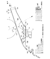
図5に示される如く、本実施形態では、自動車車体10のフード12における前端部の車幅方向中央部12Aに、周知のフードロック機構14が配設されている。
As shown in FIG. 5, in the present embodiment, a well-known
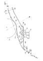
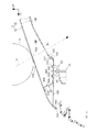
図1に示される如く、フード12はフード12の車体外側面を構成するフードアウタパネル16と、フードアウタパネル16の内側(裏面側)に配設されたフードインナパネル18とを備えており、フードアウタパネル16の前端縁部16Aとフードインナパネル18の前端縁部18Aは、ヘミング加工にて結合されている。
As shown in FIG. 1, the
フードインナパネル18には、前端縁部18Aの後方側に、補強部材取付部としてのリインフォースメント取付部18Bが車体後方に向かって略水平に形成されており、このリインフォースメント取付部18Bの上面側に、補強部材としてのフードロックリインフォースメント30が配設されている。また、フードインナパネル18のリインフォースメント取付部18Bには孔20が形成されており、この孔20にはフードロック機構14の一部を構成するストライカ22が車体上方側から車体下方側に向かって挿入されている。
On the hood
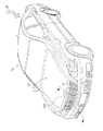
ストライカ22の前側取付部22Aと後側取付部22Bは、フードロックリインフォースメント30における取付部30Aの前側取付部30Bと後側取付部30Cとに固定されている。また、フードロックリインフォースメント30の取付部30Aは略水平に配設されており、取付部30Aの前端部には、車体前側斜め前方へ向かって前壁部30Dが形成されている。
The
フードロックリインフォースメント30の前壁部30Dの上端部には、略車体前方へ向かってフランジ30Eが形成されており、このフランジ30Eは、マスチック等の接着剤によってフードアウタパネル16に結合されている。また、フードロックリインフォースメント30における取付部30Aの後端部には、車体後側斜め上方に向ってフランジ30Fが形成されており、このフランジ30Fの上端部はフードアウタパネル16と離間している。
A
フードインナパネル18におけるリインフォースメント取付部18Bの後端部には、車体前方下側から車体後方上側に向かって縦壁部18Cが形成されており、この縦壁部18Cとフードロックリインフォースメント30のフランジ30Fとの間には隙間が形成されている。
A
フードインナパネル18におけるリインフォースメント取付部18Bの車体後方側となる縦壁部18Cの上端部18Dからは、車体前方下側から車体後方上側に向かって傾斜壁部18Eが形成されている。
An
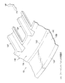
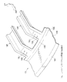
図4に示される如く、フードインナパネル18の傾斜壁部18Eは、フードインナパネル18における前方側の周囲部18Gに形成されている。また、フードインナパネル18における前方側の周囲部18Gの後方には、複数の骨部18Fが車体前後方向に沿って形成されており、骨部18Fの車体前後方向から見た断面形状は、開口部を車体上方へ向けたハット形状となっている。
As shown in FIG. 4, the
図1に示される如く、フードインナパネル18の傾斜壁部18Eの傾斜角θは、水平面に対して135度〜160度(好ましくは140度〜155度)となっている。
As shown in FIG. 1, the inclination angle θ of the
従って、衝突体Kがフード12における前端部の車幅方向中央部12Aの近傍に車体前方斜め上方(図1の矢印A方向)から車体後方下側に向かって水平面Sに対して角度α=45度〜70度で衝突した場合に、衝突体Kの衝突方向Aと傾斜壁部18Eとが略直角に近い角度になるようになっている。
Accordingly, the collision body K has an angle α = 45 with respect to the horizontal plane S in the vicinity of the vehicle width direction
次に、本実施形態の作用を説明する。 Next, the operation of this embodiment will be described.
本実施形態では、図1に示される如く、衝突体Kがフード12における前端部の車幅方向中央部12Aの近傍に車体前方斜め上方(図1の矢印A方向)から水平面Sに対して角度α=45度〜70度で衝突すると、図2に示される如く、先ず、衝突体Kが当接したフードアウタパネル16の部位16Bが車体下方へ変形する。
In the present embodiment, as shown in FIG. 1, the collision body K has an angle with respect to the horizontal plane S from the upper front side of the vehicle body (in the direction of arrow A in FIG. 1) in the vicinity of the vehicle width direction
この時、図6に示される如く、フード12の変形ストロークSと減速度Gとの関係は、変形ストロークSの増加に伴って減速度Gも増加し、変形ストロークS1で、ピーク値G1となる。
At this time, as shown in FIG. 6, the relationship between the deformation stroke S and the deceleration G of the
次に、図3に示される如く、衝突体Kによって矢印A方向へ変形した、フードアウタパネル16の部位16Bが、フードインナパネル18の傾斜壁部18Eに当接する。この時、フードインナパネル18における傾斜壁部18Eの傾斜角θが水平面に対して135度〜160度となっているため、衝突体Kの衝突方向Aと傾斜壁部18Eとが略直角に近い角度になる。
Next, as shown in FIG. 3, the
また、フードインナパネル18の傾斜壁部18Eが、フードインナパネル18の縦壁部18Cの上方に設定されている。
Further, the
この結果、図3に二点鎖線で示すように、フードインナパネル18の傾斜壁部18Eが、縦壁部18Cの上端部18Dを起点にして、下方(矢印B方向)へ回転するように容易に変形する。
As a result, as shown by a two-dot chain line in FIG. 3, the
このため、図6に示される如く、フード12の変形ストロークSと減速度Gとの関係は、変形ストロークSの増加にともなって減速度Gが大きくならず、変形ストロークS2では、変形ストロークS1におけるピーク値G1に比べて、小さいピーク値G2となる。
For this reason, as shown in FIG. 6, the relationship between the deformation stroke S and the deceleration G of the
よって、フード12の前端部の車幅方向中央部12Aから受ける衝突体Kの衝撃荷重を低減できる。
Therefore, the impact load of the collision body K received from the vehicle width direction
次に、本発明における車両用フード構造の第2実施形態を図7及び図8に従って説明する。 Next, a second embodiment of the vehicle hood structure according to the present invention will be described with reference to FIGS.
なお、第1実施形態と同一部材に付いては、同一符号を付してその説明を省略する。 In addition, about the same member as 1st Embodiment, the same code | symbol is attached | subjected and the description is abbreviate | omitted.
図7に示される如く、本実施形態では、第1実施形態におけるフードインナパネル18の傾斜壁部18Eに脆弱部を形成するための孔40が形成されている。
As shown in FIG. 7, in this embodiment, a
図8に示される如く、孔40は車幅方向に沿った矩形状となっており、車幅方向に沿って所定の間隔で複数個形成されている。また、各孔40は、フードインナパネル18の周囲部18Gにおける骨部18Fの前方の部位18Hでない位置に形成されている。
As shown in FIG. 8, the
次に、本実施形態の作用を説明する。 Next, the operation of this embodiment will be described.
本実施形態では、第1実施形態の作用効果に加えて、フードインナパネル18の傾斜壁部18Eに脆弱部を形成するための孔40を形成したことによって、衝突時Kがフードインナパネル18に衝突し、フードアウタパネル16の部位16Bが傾斜壁部18Eに当接した際に、フードインナパネル18の傾斜壁部18Eが更に変形し易くなる。このため、フード12の前端部の車幅方向中央部12Aから受ける衝突体Kの衝撃荷重を更に低減できる。
In the present embodiment, in addition to the effects of the first embodiment, by forming the
なお、第2実施形態では、フードインナパネル18の傾斜壁部18Eに脆弱部を形成するための孔40を形成したが、孔40に代えて、図9に示される如く、屈曲部44等の他の脆弱部形成手段をフードインナパネル18の傾斜壁部18Eに形成した構成としても良い。
In the second embodiment, the
以上に於いては、本発明を特定の実施形態について詳細に説明したが、本発明はかかる実施形態に限定されるものではなく、本発明の範囲内にて他の種々の実施形態が可能であることは当業者にとって明らかである。例えば、上記各実施形態では、図4に示される如く、フードインナパネル18の傾斜壁部18Eを、フードインナパネル18の前方側の周囲部18Gに形成したが、これに代えて、図10に示される如く、フードインナパネル18の傾斜壁部18Eを、フードインナパネル18を骨部18Fの前端部18Jに形成した構成としても良い。
Although the present invention has been described in detail with reference to specific embodiments, the present invention is not limited to such embodiments, and various other embodiments are possible within the scope of the present invention. It will be apparent to those skilled in the art. For example, in each of the above embodiments, as shown in FIG. 4, the
12 フード
14 フードロック機構
16 フードアウタパネル
18 フードインナパネル
18A フードインナパネルの前端縁部
18B フードインナパネルのリインフォースメント取付部(補強部材取付部)
18C フードインナパネルの縦壁部
18D フードインナパネルの縦壁部の上端部
18E フードインナパネルの傾斜壁部
18F フードインナパネルの骨部
18G フードインナパネルの周囲部
18H フードインナパネルの周囲部における骨部の前方の部位
18J フードインナパネルの骨部の前端部
30 フードロックリインフォースメント(補強部材)
40 孔
44 屈曲部
12
18C Vertical wall portion of the hood
40
Claims (1)
前記フードインナパネルの前部に形成され、前記補強部材が固定された補強部材取付部と、
前記フードインナパネルにおける前記補強部材取付部の車体後方側において前記フランジに沿って車体前方下側から車体後方上側に向かって形成された縦壁部と、
前記フードインナパネルにおける前記縦壁部の上端部から車体後方上側に向かって形成され、傾斜角が水平面に対して135度〜160度の傾斜壁部と、
を有することを特徴とする車両用フード構造。 Is disposed between the hood outer panel and a hood inner panel in the front end portion of the hood, the reinforcing member flange formed toward the Oite vehicle body rear side obliquely upward to the rear end portion is separated from the hood outer panel,
A reinforcing member mounting portion formed at a front portion of the hood inner panel, to which the reinforcing member is fixed;
A vertical wall portion formed toward the rear of the vehicle body upward from the vehicle body front lower side along the Oite the flange on the rear side of the vehicle body of the reinforcing member mounting portion of the hood inner panel,
An inclined wall portion that is formed from the upper end portion of the vertical wall portion in the hood inner panel toward the rear upper side of the vehicle body, and has an inclination angle of 135 degrees to 160 degrees with respect to a horizontal plane;
A vehicle hood structure characterized by comprising:
Priority Applications (1)
| Application Number | Priority Date | Filing Date | Title |
|---|---|---|---|
| JP2004163473A JP4200941B2 (en) | 2004-06-01 | 2004-06-01 | Vehicle hood structure |
Applications Claiming Priority (1)
| Application Number | Priority Date | Filing Date | Title |
|---|---|---|---|
| JP2004163473A JP4200941B2 (en) | 2004-06-01 | 2004-06-01 | Vehicle hood structure |
Publications (3)
| Publication Number | Publication Date |
|---|---|
| JP2005343262A JP2005343262A (en) | 2005-12-15 |
| JP2005343262A5 JP2005343262A5 (en) | 2007-06-28 |
| JP4200941B2 true JP4200941B2 (en) | 2008-12-24 |
Family
ID=35496039
Family Applications (1)
| Application Number | Title | Priority Date | Filing Date |
|---|---|---|---|
| JP2004163473A Expired - Fee Related JP4200941B2 (en) | 2004-06-01 | 2004-06-01 | Vehicle hood structure |
Country Status (1)
| Country | Link |
|---|---|
| JP (1) | JP4200941B2 (en) |
Families Citing this family (4)
| Publication number | Priority date | Publication date | Assignee | Title |
|---|---|---|---|---|
| JP5719721B2 (en) * | 2011-08-22 | 2015-05-20 | 本田技研工業株式会社 | Vehicle hood |
| JP6119705B2 (en) * | 2014-09-19 | 2017-04-26 | マツダ株式会社 | Automotive hood structure |
| JP6409566B2 (en) * | 2014-12-25 | 2018-10-24 | トヨタ自動車株式会社 | Vehicle hood structure |
| JP2016150631A (en) * | 2015-02-17 | 2016-08-22 | スズキ株式会社 | Center pillar upper trim |
-
2004
- 2004-06-01 JP JP2004163473A patent/JP4200941B2/en not_active Expired - Fee Related
Also Published As
| Publication number | Publication date |
|---|---|
| JP2005343262A (en) | 2005-12-15 |
Similar Documents
| Publication | Publication Date | Title |
|---|---|---|
| JP4407755B2 (en) | Vehicle hood structure | |
| US7090289B2 (en) | Vehicle hood | |
| US10596994B2 (en) | Front structure of vehicle | |
| JP2005075176A (en) | Structure of hood for vehicle | |
| CN112065179B (en) | Engine cover for vehicle | |
| JP4122680B2 (en) | Vehicle fender structure | |
| JP4407599B2 (en) | Body front support structure | |
| JP2005096629A (en) | Vehicle hood structure | |
| JP2005343279A (en) | Hood structure for vehicle | |
| JP2005145224A (en) | Hood structure for vehicle | |
| JP2004203158A (en) | Front part structure of automobile | |
| JP2005125831A (en) | Hood structure of vehicle | |
| JP4383425B2 (en) | Vehicle hood structure | |
| JP4200941B2 (en) | Vehicle hood structure | |
| JP2019177814A (en) | Vehicle body structure | |
| JP4685906B2 (en) | Vehicle hood structure | |
| JP4457909B2 (en) | Cowl louva | |
| JP2009274538A (en) | Automobile hood | |
| JP4036219B2 (en) | Automotive engine hood structure | |
| CN110304006B (en) | Vehicle grille periphery structure, vehicle grille, and method for manufacturing vehicle grille periphery structure | |
| JP2005119512A (en) | Hood structure for vehicle | |
| JP2009045996A (en) | Cowl structure of four wheel vehicle | |
| JP4774804B2 (en) | Automotive engine hood structure | |
| JP2009184527A (en) | Pillar reinforcement structure | |
| JP2008012946A (en) | Vehicle room material structure |
Legal Events
| Date | Code | Title | Description |
|---|---|---|---|
| A521 | Written amendment |
Free format text: JAPANESE INTERMEDIATE CODE: A523 Effective date: 20070515 |
|
| A621 | Written request for application examination |
Free format text: JAPANESE INTERMEDIATE CODE: A621 Effective date: 20070515 |
|
| A131 | Notification of reasons for refusal |
Free format text: JAPANESE INTERMEDIATE CODE: A131 Effective date: 20080527 |
|
| A977 | Report on retrieval |
Free format text: JAPANESE INTERMEDIATE CODE: A971007 Effective date: 20080529 |
|
| A521 | Written amendment |
Free format text: JAPANESE INTERMEDIATE CODE: A523 Effective date: 20080711 |
|
| TRDD | Decision of grant or rejection written | ||
| A01 | Written decision to grant a patent or to grant a registration (utility model) |
Free format text: JAPANESE INTERMEDIATE CODE: A01 Effective date: 20080916 |
|
| A01 | Written decision to grant a patent or to grant a registration (utility model) |
Free format text: JAPANESE INTERMEDIATE CODE: A01 |
|
| A61 | First payment of annual fees (during grant procedure) |
Free format text: JAPANESE INTERMEDIATE CODE: A61 Effective date: 20080929 |
|
| FPAY | Renewal fee payment (event date is renewal date of database) |
Free format text: PAYMENT UNTIL: 20111017 Year of fee payment: 3 |
|
| FPAY | Renewal fee payment (event date is renewal date of database) |
Free format text: PAYMENT UNTIL: 20111017 Year of fee payment: 3 |
|
| FPAY | Renewal fee payment (event date is renewal date of database) |
Free format text: PAYMENT UNTIL: 20121017 Year of fee payment: 4 |
|
| FPAY | Renewal fee payment (event date is renewal date of database) |
Free format text: PAYMENT UNTIL: 20121017 Year of fee payment: 4 |
|
| FPAY | Renewal fee payment (event date is renewal date of database) |
Free format text: PAYMENT UNTIL: 20131017 Year of fee payment: 5 |
|
| LAPS | Cancellation because of no payment of annual fees |