JP4194205B2 - Inkjet recording device - Google Patents
Inkjet recording device Download PDFInfo
- Publication number
- JP4194205B2 JP4194205B2 JP2000051579A JP2000051579A JP4194205B2 JP 4194205 B2 JP4194205 B2 JP 4194205B2 JP 2000051579 A JP2000051579 A JP 2000051579A JP 2000051579 A JP2000051579 A JP 2000051579A JP 4194205 B2 JP4194205 B2 JP 4194205B2
- Authority
- JP
- Japan
- Prior art keywords
- recording medium
- recording
- ink jet
- platen
- recording apparatus
- Prior art date
- Legal status (The legal status is an assumption and is not a legal conclusion. Google has not performed a legal analysis and makes no representation as to the accuracy of the status listed.)
- Expired - Fee Related
Links
Images


Classifications
-
- B—PERFORMING OPERATIONS; TRANSPORTING
- B41—PRINTING; LINING MACHINES; TYPEWRITERS; STAMPS
- B41J—TYPEWRITERS; SELECTIVE PRINTING MECHANISMS, i.e. MECHANISMS PRINTING OTHERWISE THAN FROM A FORME; CORRECTION OF TYPOGRAPHICAL ERRORS
- B41J11/00—Devices or arrangements of selective printing mechanisms, e.g. ink-jet printers or thermal printers, for supporting or handling copy material in sheet or web form
- B41J11/0045—Guides for printing material
- B41J11/005—Guides in the printing zone, e.g. guides for preventing contact of conveyed sheets with printhead
-
- B—PERFORMING OPERATIONS; TRANSPORTING
- B41—PRINTING; LINING MACHINES; TYPEWRITERS; STAMPS
- B41J—TYPEWRITERS; SELECTIVE PRINTING MECHANISMS, i.e. MECHANISMS PRINTING OTHERWISE THAN FROM A FORME; CORRECTION OF TYPOGRAPHICAL ERRORS
- B41J11/00—Devices or arrangements of selective printing mechanisms, e.g. ink-jet printers or thermal printers, for supporting or handling copy material in sheet or web form
- B41J11/02—Platens
- B41J11/06—Flat page-size platens or smaller flat platens having a greater size than line-size platens
-
- B—PERFORMING OPERATIONS; TRANSPORTING
- B41—PRINTING; LINING MACHINES; TYPEWRITERS; STAMPS
- B41J—TYPEWRITERS; SELECTIVE PRINTING MECHANISMS, i.e. MECHANISMS PRINTING OTHERWISE THAN FROM A FORME; CORRECTION OF TYPOGRAPHICAL ERRORS
- B41J13/00—Devices or arrangements of selective printing mechanisms, e.g. ink-jet printers or thermal printers, specially adapted for supporting or handling copy material in short lengths, e.g. sheets
- B41J13/02—Rollers
-
- B—PERFORMING OPERATIONS; TRANSPORTING
- B41—PRINTING; LINING MACHINES; TYPEWRITERS; STAMPS
- B41J—TYPEWRITERS; SELECTIVE PRINTING MECHANISMS, i.e. MECHANISMS PRINTING OTHERWISE THAN FROM A FORME; CORRECTION OF TYPOGRAPHICAL ERRORS
- B41J13/00—Devices or arrangements of selective printing mechanisms, e.g. ink-jet printers or thermal printers, specially adapted for supporting or handling copy material in short lengths, e.g. sheets
- B41J13/10—Sheet holders, retainers, movable guides, or stationary guides
- B41J13/14—Aprons or guides for the printing section
Landscapes
- Ink Jet (AREA)
- Delivering By Means Of Belts And Rollers (AREA)
- Handling Of Sheets (AREA)
- Separation, Sorting, Adjustment, Or Bending Of Sheets To Be Conveyed (AREA)
- Feeding Of Articles By Means Other Than Belts Or Rollers (AREA)
- Handling Of Cut Paper (AREA)
Description
【0001】
【発明の属する技術分野】
本発明は、記録手段を用いて記録媒体にインクを付着することにより、文字、図形、パターンなどの画像を記録する記録装置に関する。
【0002】
【従来の技術】
記録媒体にインク液滴を付着させて記録を行う場合、インクが記録媒体に吸収されると、この部分で記録媒体は膨潤する。この際、記録媒体に付着されるインクの濃度差により、伸縮の差が有る部分が生じ、大きく伸びた部分がシート状の記録媒体の記録面に垂直な方向に撓んで、いわゆるコックリングと呼ばれる凹凸が生じる。この際、時間が経つほどインク液滴が記録媒体に吸収され膨潤するので生じる凹凸は大きくなる。イメージデータなどを記録する場合、記録媒体の送りピッチを小さくし、かつイメージデータをランダムに分割し、記録手段を載置して移動するキャリッジの走査回数を多くして記録することにより、送りピッチのむらによる記録品位への影響を小さくする手法が採られているが、この様に送りピッチが小さい場合には、記録時間が長くなり、コックリングが大きくなる。このため、記録動作中に、記録媒体を記録手段に対向する位置に支持するプラテン側から記録手段の方に向かって記録媒体が撓んで紙浮きが発生し、その結果、記録手段と記録媒体とが接触してこすれ、画像の品位が損なわれてしまう場合がある。
【0003】
インクを吐出して記録を行うインクジェット記録方式の記録装置では、吐出されたインクの飛行経路が短い方がインクの付着位置の精度を高くできる。そこでこの記録装置では、鮮明で高品位な記録結果を得るために、記録媒体の記録面と記録ヘッドの間隔(以下、「ヘッドギャップ」と称す。)をできるだけ狭く設定することが求められている。一方、ヘッドギャップを狭くすると、上記のような記録手段と記録媒体とのこすれが発生しやすくなる。
【0004】
そこで、ヘッドギャップを狭くしても記録手段と記録媒体とのこすれが発生しないように、コックリングによる紙浮きを小さくする方法が求められている。
【0005】
記録媒体のプラテンからの紙浮きを防止する構成として、特開昭61−95966号公報や特開平3−29359号公報には、プラテンに複数の小孔が設けられており、負圧発生手段を用いて小孔を介して記録媒体に吸引力を作用させ、記録媒体をプラテンに密着させる構成(第1の従来例)が開示されている。
【0006】
また、特開平4−69264号公報には、記録媒体の搬送方向の上流側において、紙押え部材によって記録媒体をプラテン側に押し付ける機構(第2の従来例)が開示されている。
【0007】
さらに、特開平9−48161号公報には、平プラテン上に記録媒体の搬送方向に延在するリブをその搬送方向と交差する方向に複数配置し、そのリブの上流側には各リブの先端部とともに記録媒体を挟持する押え板を搬送方向と交差する方向に延在させて配置するインクジェット記録装置(第3の従来例)が開示されている。また、このインクジェット記録装置には、リブとリブとの間に対応する押え板の部位に、下方に記録媒体を付勢する突起が設けられている。
【0008】
【発明が解決しようとする課題】
前記した第1の従来例では、負圧発生手段が必要であり、装置が大掛かりにりコスト高となる。そして、吸気および排気時の騒音が大きいという問題がある。また、サイズの小さな記録媒体に記録を行う場合、プラテンに設けられた複数の小孔のうちの一部でも記録媒体外に位置して開放されると、吸引効率が著しく低下して信頼性に乏しくなる。必ず全ての小孔が記録媒体に覆われるように配置すると、逆に大きなサイズの記録媒体に対して全面的に吸引力を及ぼすことができずやはり信頼性に乏しくなる。これを解決するためには、小さなサイズの記録媒体を用いる際に記録媒体外に位置する小孔を塞ぐための手段が必要になり、構成がかなり複雑かつ高コストになる。
【0009】
第2の従来例では、記録領域が広い場合には、記録媒体をプラテンに密着させることが不十分になるおそれがある。すなわち、この構成で、記録媒体は、上流側で紙押え部材によりプラテンに向けて押圧され、下流側では排紙ローラなどにより挟持されるが、両者の間の記録領域などにおいてはプラテンに向けて押圧されることはない。したがって、記録ヘッドの1行分の記録幅が広く記録領域が広いと、上流側の紙押え部材と下流側の排紙ローラで押さえただけでは、肝心の記録領域において記録媒体がプラテンから浮いてしまったり記録媒体に皺がよったりするおそれがある。さらに、紙浮きを抑えるために、排紙ローラ対の挟持部位をプラテンの記録媒体案内面よりも低くすると、記録シートが紙押え部材から離れた後、記録媒体の後端が浮き上がってしまうという問題がある。
【0010】
第3の従来例では、リブの上流側には必ずリブの先端部にほぼ当接する位の位置に紙押え板が配されているが、リブの先端部と紙押え板とによる記録媒体の挟持からは、記録媒体をプラテン側に付勢することはできない。また、互いに隣り合うリブの間隙の上流の紙押え板の下面に設けられている突起では、リブとリブとの間に位置する記録媒体をプラテン方向に付勢する効果はあるものの、厚紙などの比較的剛性の高い記録媒体を搬送する場合や広い記録領域に記録を実行する場合には、記録媒体がプラテンから浮き上がることを完全には防止することができないという問題がある。
【0011】
そこで、本発明の目的は、低コストかつ簡単な構成で前述のような課題を解決して、記録媒体の記録手段側への浮き上がりを防止することができるインクジェット記録装置を提供することにある。
【0012】
また、本発明の他の目的は、インクジェット記録手段を用いて記録媒体にインク滴を付着させて記録を行うインクジェット記録装置において、
記録媒体をインクジェット記録手段と対向する位置に支持するプラテンと、
インクジェット記録手段により記録媒体にインクが付着される位置に当該記録媒体を挟持して搬送する複数の搬送ローラ対と、
プラテンに対して記録媒体の搬送方向に延在するとともに記録媒体の搬送方向と交差する方向に複数並設されて記録媒体の裏面側を支持する突起とを含み、突起夫々の記録媒体の搬送方向上流側延長線上には、搬送ローラ対が位置することを特徴とするインクジェット記録装置を提供することにある。
【0013】
また、本発明のさらに他の目的は、記録領域よりも上流側に配置され、複数対のローラを備えた搬送ローラユニットと、搬送ローラユニットの下流側に配置され、記録手段と対向する位置で記録媒体を支持するプラテンとを有するインクジェット記録装置において、
搬送ローラユニットが、複数対のローラにより記録媒体を挟持する挟持部と、非挟持部と
プラテンに設けられた、記録媒体搬送方向に沿って挟持部の延長線上に位置し、かつ記録媒体搬送方向に沿って延びる複数のリブと、
記録媒体のサイズにかかわらず記録媒体の一方の端部が揃えられる搬送基準位置とを含み、
複数のリブのうちの一つが、定形サイズの記録媒体の他方の端部から1mm〜10mm内側に位置するように配設されていることを特徴とするインクジェット記録装置を提供することにある。
【0014】
【課題を解決するための手段】
上記の課題を解決するため、本発明によるインクジェット記録装置は、インクジェット記録手段を用いて記録媒体にインク滴を付着させて記録を行うインクジェット記録装置において、
記録媒体をインクジェット記録手段と対向する位置に支持するプラテンと、
インクジェット記録手段により記録媒体にインクが付着される位置に当該記録媒体を挟持して搬送する複数の搬送ローラ対と、
プラテンに対して記録媒体の搬送方向に延在するとともに記録媒体の搬送方向と交差する方向に複数並設されて記録媒体の裏面側を支持する突起とを含み、突起夫々の記録媒体の搬送方向上流側延長線上には、搬送ローラ対が位置することを特徴とする。
【0015】
この構成によれば、記録媒体を、裏面側を突起に当接させてプラテン上に浮き上がらないように保持できる。特に、記録媒体に膨潤が生じると、記録媒体は、隣り合うリブの間でプラテン側に向かって撓み、搬送方向に垂直な方向に波状に変形する。記録媒体がこのように変形すると、搬送方向に平行な方向には変形し難くなる。また、搬送方向に垂直な方向への膨潤による変形は、リブ間の撓みが大きくなることにより吸収される。したがって、記録媒体がインクジェット記録手段側に近づくように変形して紙浮きが発生することを抑止できる。
【0016】
複数の突起として、記録媒体の搬送方向上流側端部の位置が異なる突起が含まれる構成とすれば、端部がより下流側にある突起部分で、記録媒体のプラテンへの当接位置がより下流側になることにより、搬送ローラ対により記録媒体をプラテンへ押し付ける力が、より下流側に対しても作用するようにできる。
【0017】
このように記録媒体の搬送方向上流側端部の位置が異なる突起を、搬送方向上流側端部の位置がより上流側のものと、そうでないものとを交互に並設するように設ければ、搬送ローラ対により記録媒体をプラテンへ押し付ける力を、搬送方向に垂直な方向にわたって実質的に均等に配分されるようにし、効率的に作用させるようにできる。
【0018】
本発明において、搬送ローラ対を、記録媒体のインク滴付着面側に接触するローラが対向するローラよりも記録媒体搬送方向下流側にずれた位置に配置されるように構成すれば、記録媒体を複数の突起に効果的に押しつけるように挟持搬送させることができ、押し付ける力をより下流側まで作用させることができる。
【0019】
また、本発明によるインクジェット記録装置は、記録領域よりも上流側に配置され、複数対のローラを備えた搬送ローラユニットと、搬送ローラユニットの下流側に配置され、記録手段と対向する位置で記録媒体を支持するプラテンと、を有するインクジェット記録装置において、
搬送ローラユニットに配され、複数対のローラにより記録媒体を挟持する挟持部と、非挟持部と、
プラテンに配され、記録媒体搬送方向に沿って前記挟持部の延長線上であって、前記記録媒体搬送方向に沿って延びる複数のリブと、
記録媒体の一方の端部が揃えられる搬送基準位置と、を有し、
複数のリブのうちの一つが、定形サイズの記録媒体の他方の端部から1mm〜10mm内側に位置するように配設されていることを特徴とする。
【0020】
この構成によれば、記録媒体の搬送基準位置が設定された端部および他方の端部とも、それぞれの端部の内側の、端部近傍に位置するリブを支点とし、記録媒体端部における浮き上がりを抑制することができる。
【0021】
記録領域の下流側に、記録媒体を搬送する排紙ローラユニットが設けられており、排紙ローラユニットが、少なくとも1対のローラにより記録媒体を挟持する挟持部と、非挟持部とを有し、挟持部が記録媒体搬送方向に沿ってリブの略延長線上に位置している構成としてもよい。この場合、記録媒体の先端が垂れ下がっても、その記録媒体の後端が反動で浮き上がろうとする動作を抑制することができる。
【0022】
排紙ローラユニットが2列配置されていてもよい。そして、排紙ローラユニットは、上流側の排紙ローラユニットよりも下流側の排紙ローラユニットの方が、ローラの個数が少ない構成とすると、構成が簡単になる。
【0023】
排紙ローラユニットが、排紙ローラと、排紙ローラの回転中心に対し上流側にずれた位置に回転中心を有し、排紙ローラおよびプラテンに向かって記録媒体を押圧する従動ローラとを含むと、記録媒体が搬送ローラユニットから離れてもプラテンに向かって押圧する力を維持し得る。
【0024】
排紙ローラが、記録媒体搬送方向に対し交差する方向に複数個に分割されていてもよい。
【0025】
本発明によるインクジェット記録装置は、記録媒体の紙浮きが小さいため、記録手段とプラテンの間隔(ヘッドギャップ)を小さくできる。そこで、本発明をインクを吐出して記録媒体に付着させるインクジェット記録方式の記録手段を有する記録装置に適用すると、ヘッドギャップを小さくして、吐出インクの付着位置精度の高い高品位の記録装置とすることができる。
【0026】
【発明の実施の形態】
以下本発明の実施形態について図面を参照して説明する。
【0027】
[第1の実施形態]
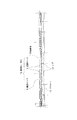
図1に、本発明の第1の実施形態の記録装置の記録領域周辺部の断面図が示されており、図2にその概略斜視図が示されている。
【0028】
図1に示すように、本実施形態の記録装置は、記録媒体に向けてインク的を吐出して付着させ画像などの記録を行うインクジェット記録方式の記録ヘッド1を有している。
【0029】
まず、記録手段の走査機構について説明する。この記録ヘッド1は、キャリッジ2に着脱自在に搭載されている。キャリッジ2は、ガイドレール3に摺動自在に支持され、かつキャリッジ2から突出したガイドコロ4が支持レール5上で回転可能に支持されている。したがって、不図示のキャリッジモータによりタイミングベルト6を介して駆動されると、キャリッジ2は、ガイドレール3と支持レール5に沿って走査する。このキャリッジ2の走査に同期して、キャリッジ2に搭載された記録ヘッド1から記録媒体7の所定位置にインク滴を吐出して画像などの記録が行われる。
【0030】
次に、記録媒体7の搬送機構について説明する。搬送経路の記録ヘッド1の上流側には、不図示のモータにより駆動される搬送ローラ8と、この搬送ローラ8に付勢ばね11によって圧接され従動回転する従動ローラ9とからなる搬送ローラ対10が配されている。従動ローラ9の回転中心は、搬送ローラ8の回転中心よりも搬送方向の下流側にずれた位置にある。したがって、搬送ローラ対10は記録媒体7を斜め下向きに送り出し、プラテン19に押し付けるように搬送する。すなわち、従動ローラ9がプラテン19に記録媒体7を押し付ける押し付けローラの役割を担っている。本実施形態では、各従動ローラ9をそれぞれ独立して付勢ばね11により付勢するように構成すれば、記録媒体7の各部の変形量に応じて適切に押圧することができる。
【0031】
プラテン19は記録ヘッド1に対向するように配置され、記録媒体7の案内面には搬送方向に沿ってのびた突起状のリブ(突起)17が搬送方向に交差する方向に並んで複数形成されている。従動ローラ9は、このリブ17に対応して複数設けられており、従動ローラ9の回転軸方向の中心位置とリブ17の中心位置とが搬送方向に同一線上に位置するように配置されている。
【0032】
搬送経路の記録ヘッド1の下流側には、不図示のモータにより駆動される排紙ローラ12と、排紙ローラ12に付勢ばね15によって圧接され従動回転する排紙用回転体である拍車13とからなる排紙ローラ対14が設けられている。この拍車13は、記録後の記録面に接触しても記録像を乱すことがないように記録媒体7との接触面積を小さくしたものである。排紙ローラ対14は、記録媒体7を挟持するニップ部分(挟持部分)と記録媒体に接触しない部分(非挟持部分)を搬送方向に交差する方向に交互に有しており、ニップ部分とリブ17の頂点の位置とが搬送方向に沿って同一直線上に並ぶように配置されている。リブ17の搬送方向上流には、必ずニップ部分が位置する。
【0033】
次に、この記録装置による記録動作について説明する。
【0034】
記録媒体7は不図示の給紙機構により、搬送ローラ対10のニップ部分まで給紙され、搬送ローラ対10の回転によりプラテン19上を記録ヘッド1に対向する記録位置まで搬送される。記録ヘッド1は、キャリッジ2の走査により記録位置まで導かれ、記録媒体7上にインクを付着する記録動作を行う。この記録動作中、搬送ローラ対10は記録媒体7を所定のピッチで紙送りし、紙送りにより記録媒体7が排紙ローラ対14に到達すると、排紙ローラ対14と搬送ローラ対10の両者で紙送りを行う。記録媒体7の後端が搬送ローラ対10から離れた後は、排紙ローラ対14のみにより紙送りが行われ、記録動作が終了すると、排紙ローラ対14は記録媒体7を不図示の排紙トレイに排出する。
【0035】
次に、図3,4を用いて記録動作前後の記録媒体7の挙動について、特にコックリングが発生しやすい薄手の記録媒体である普通紙を想定して説明する。図3および図4は図1において矢印A方向に見た図であり、図3は記録前の普通紙の状態を示し、図4は記録後にコックリングが発生した普通紙の状態を示したものである。
【0036】
記録媒体7は、従動ローラ9によりプラテン19に斜め上方から押し付けられて搬送される。すなわち、従動ローラ9が、搬送ローラ8の回転中心よりも下流側にずれた位置に回転中心を有しているため、従動ローラ9による押圧が搬送ローラ8のみでは吸収されず記録媒体7をプラテン19に押し付ける方向にも作用する。このようにしてプラテン19に斜めに突き当てられた記録媒体7は搬送ローラ対10との接触面とプラテン19との接触面との間で湾曲し、記録媒体7をプラテン19に押し付ける付勢力が生じる。この付勢力は、リブ17の中心と従動ローラ9の回転軸方向の中心位置とを記録媒体7の搬送方向に沿って同一直線上に配置することで、最も効果的に得られるが、少なくとも、リブ17の、記録媒体7の搬送方向上流の領域内に必ず従動ローラ9の幅に対応する該従動ローラ9を配置することで、ほぼ同等の付勢力を得ることができる。このように、プラテン19に押し付けられた記録媒体7は、リブ17に突き当たり、リブ17間では撓んで凹形状をなし、図3に示すようにリブ17との接触面を頂点とする緩やかな波状に変形する。
【0037】
次に、主な溶剤として水を用いた記録用のインクが記録ヘッド1により記録媒体7に付着されると、記録媒体7は水分を吸収することにより膨潤し、コックリングが発生する。この際、記録媒体7のリブ17との接触面では、押し付け力が働いているため紙浮きは起こりにくい。一方、記録媒体7がプラテン19と接触していない部分、すなわちリブ17間の部分では、記録前の記録媒体7の変形方向であるプラテン側に変形(コックリング)が生じる。すなわち、記録前の記録媒体7の波打ち量Xが、記録後は波打ち量X+ΔXとなり、このようにリブ17間における凹状の撓みにより記録媒体7の膨潤による変形をほとんど吸収できる。また、リブ17により記録媒体7は搬送方向に垂直な方向の波状の変形を生じ易く、搬送方向の変形は起こり難い。このように、本実施形態によれば、記録媒体7の膨潤による変形は、プラテン19側への波状の変形量の増大により吸収され、記録ヘッド1側への紙浮きを抑制できる。紙浮きを抑制することにより、記録媒体7と記録ヘッド1とが接触して画像に悪影響が生じることを抑制できる。なお、排紙ローラ対14は、記録媒体7のこの波状の変形の山、すなわちリブ17の頂点部分に位置した部分のみを挟持する構成としているので、記録媒体7の変形を矯正して、上記のような記録媒体7の波状の変形による効果を損なうことはない。また、搬送ローラ対10から記録媒体7が離れた後も、排紙ローラ対14によるプラテンリブ17への記録媒体7の押し付けがなくなったことで、紙浮きを抑えることができる。
【0038】
本実施形態によれば、紙浮きを抑制できるので、記録ヘッド1とプラテン19の間隔(ヘッドギャップ)を狭くすることが可能となる。特にインクジェット記録方式の記録ヘッド1を用いた場合には、ヘッドギャップを狭くすることにより、吐出インクの飛行距離が短くなり、インクの付着位置の精度の高い高品位の記録装置とすることができる。
【0039】
[第2の実施形態]
第2の実施形態に係る記録装置について図5を用いて説明する。図5において、第1の実施形態と同様の部分については、同一の符号を付し説明を省略する。
【0040】
図5において、搬送ローラ対10は、搬送ローラ8と、回転軸方向に複数の凹凸形状を有する従動ローラユニット9’とによって構成され、従動ローラユニット9’の凸部の回転軸方向の略中心位置とリブ17とが搬送方向に同一直線上に位置するように配置されている。特に、リブ17の搬送方向上流延長線上には必ず従動ローラー9と搬送ローラ8とのニップ部分が位置する。
【0041】
このように、第1の実施形態と同様な従動ローラ9を複数個ずつ軸20により連結した従動ローラユニット9’を用いることにより、ローラの支持機構や付勢ばねなどの部品数を減らして構成を簡単にし、コストを低減できる。本実施形態では、従動ローラ9を3個ずつ軸20により連結して従動ローラユニット9’を構成している。
【0042】
以上説明したように、上述の第1および第2の実施形態によれば、記録動作中の記録媒体7を波状にし、記録媒体7をプラテン19に押し付けることにより、記録媒体7がインクを吸収して膨潤することにより生じるコックリングを波打ち量の増大により吸収して、紙浮きを抑制できる。さらに、波状に変形した記録媒体7は搬送方向に変形し難いため、排紙ローラ対14によってプラテンへ記録媒体7を押しつけても記録媒体7の後端に紙浮きが発生し難い。紙浮きを抑制できるので、記録媒体7の記録面と記録ヘッド1との間隔を狭くし、高品位な記録を行うことができる。
【0043】
また、部品点数を増やすことなく紙浮きを抑制できるので、コスト的にも有効である。
【0044】
[第3の実施形態]
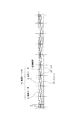
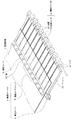
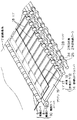
本発明の第3の実施形態の記録装置について説明する。図6には記録領域周辺部の断面図が示されており、図7にはその概略斜視図が示されている。
【0045】
前述の第1および第2の実施形態と、第3〜第5の実施形態との相違は、リブ17の他に、以下に説明するリブ18を備えていることである。よって、第1、第2の実施形態と共通する構成については同じ番号を援用する。
【0046】
まず、記録領域近傍の構成について説明する。図6および図7に示すように、記録ヘッド1の対向位置には、記録媒体7を案内支持するプラテン19が配置されている。プラテン19には、記録媒体7の搬送方向に沿って延びる突起である複数のリブ17,18が、搬送ローラユニット10の複数の挟持部分の下流側延長線上にそれぞれ形成されている。リブ17とリブ18とは長さが異なっており、短いリブ18は、長いリブ17に比べ、搬送方向の下流側にリブの始点を有している。
【0047】
記録ヘッド1による記録領域よりも下流側には、記録領域を通過した記録媒体7を不図示の排紙トレイに排出するための、排紙ローラ12と、付勢ばね15によって排紙ローラ12に圧接され従動回転する拍車13とからなる排紙ローラユニット14が設けられている。拍車13は、記録媒体7との接触面積が小さく、記録後の記録面に接触しても記録媒体の記録像をできるだけ乱すことがないように形成されている。この排紙ローラユニット14の挟持部分は、リブ17,18および搬送ローラユニット10の挟持部分の略下流側延長線上に設けられている。特に、リブ17とリブ18との搬送方向上流延長線上には、必ず搬送ローラユニット10の挟持部分が位置する。
【0048】
次に、この記録装置における記録動作について説明する。不図示の給紙機構により、記録媒体7が搬送ローラユニット10の搬送ローラ8と従動ローラ9との挟持部分まで給送されると、斜行等を矯正された後、記録媒体7は、搬送ローラユニット10の搬送ローラ8および従動ローラ9の回転により記録ヘッド1による記録領域に搬送される。
【0049】
この記録領域において、記録媒体7の搬送が一旦停止した間に、キャリッジ2がガイドレール3および支持レール5に沿って走査する。そして、キャリッジ2の走査に同期して、キャリッジ2に搭載された記録ヘッド1から記録媒体の所定位置にインク滴を吐出して1行分の記録が行なわれる。1行分の走査および記録が完了すると、搬送ローラユニット10により、記録媒体7が1行分搬送される。そこで再び記録媒体7の搬送が停止し、キャリッジ2の走査および記録ヘッド1による1行分の記録が行われる。こうして、記録媒体7の搬送と記録ヘッド1による記録とが交互に行われて、記録媒体7全面への記録が行われる。
【0050】
なお、記録媒体7の先端が排紙ローラユニット14の排紙ローラ12と拍車13との挟持部分まで到達すると、搬送ローラユニット10の搬送ローラ8および従動ローラ9の回転に加えて排紙ローラユニット14の排紙ローラ12および拍車13の回転により、記録媒体7が搬送される。さらに、記録媒体7の後端が搬送ローラユニット10の搬送ローラ8と従動ローラ9との挟持部分から離脱すると、排紙ローラユニット14の排紙ローラ12および拍車13の回転のみにより、記録媒体7は搬送される。
【0051】
前記の通り記録媒体7全面への記録が完了すると、排紙ローラユニット14により記録済みの記録媒体7は図示しない排紙トレイへ排出される。
【0052】
次に、記録前後の記録媒体7の挙動、特にコックリングが発生しやすい薄手の記録媒体である普通紙の挙動について、図7〜図10を参照して説明する。
【0053】
図7,図8に示すように、従動ローラ9の回転中心が搬送ローラ8の回転中心に対して搬送方向下流側にずらしてあることにより、普通紙(記録媒体)7はプラテン19のリブ17に押し付けられながら搬送される。すなわち、従動ローラ9の回転中心がずれているため、従動ローラ9の押圧力は搬送ローラ8に吸収されるのみならず、プラテン19に向かう方向にも作用する。従って、普通紙7は斜め下方に押し付けられつつ搬送される。この時、普通紙7は、図8に示すように、リブ17に沿うと同時に、リブ17間ではその付勢力により凹形状を成し、図7に2点鎖線70で示すような、緩やかな波打ち形状が付与される。
【0054】
さらに普通紙が搬送されると、リブ17間で凹部状になっていた部分(普通紙7の先端)がリブ18に当接して押し上げられ、図9に示すように、リブ17およびリブ18を頂点とする波打ち形状が付与される。本実施形態では、リブ18の始点を、リブ17の始点よりも搬送方向下流に位置させたことにより、搬送ローラユニット10が普通紙(記録媒体)7をプラテン19方向へ押圧する力は、より下流側まで持続することが可能となる(この時の波打ち量は図9にXで示している)。
【0055】
記録ヘッド1の記録動作により、主な溶剤として水を用いたインクが普通紙7に付着すると、普通紙7は水分を吸収することにより膨潤し、図10に示すようにコックリングが発生する。本実施形態では、従動ローラ9の下流側延長線上にリブ17、18が配置されているので、搬送ローラユニット10の挟持部分に確実に挟持されていた部分がリブ17、18に押し付けられる。従って、膨潤による大きな変形が発生しても、それはほとんどリブ17,18間におけるプラテン側への撓み量の増大によって吸収される。すなわち、プラテン19上のリブ17、18間では、あらかじめ普通紙7は波打ち形状の凹部になっており、膨潤後も搬送ローラユニット10が普通紙7をリブ17,18へ向けて押圧する力は保たれるので、コックリングは図10において下向きに発生し、リブ17,18間で記録紙7は図10に(X+△X)で示す波打ち量の凹部となって、記録ヘッド1側への紙浮きは防止される。
【0056】
そして、記録領域においてコックリングの発生した普通紙7は、排紙ローラユニット14により、不図示の排紙トレイへと搬送されるが、排紙ローラユニット14は搬送方向に沿ってリブ17、18と略同一直線上に配置されているので、記録領域での緩やかな波打ち状態やコックリングによる凹凸を変化させることがない。
【0057】
通常の記録装置においては、使用される記録媒体(記録紙)のサイズは予めある程度決まっている。例えば、一般的なプリンター等では、例えば、葉書、B5判、A4LTR(レターサイズ)、B4判、LDR(レジャーサイズ)、A3判のいずれかの記録媒体を使用することが前提とされている。そこで本実施形態では、使用される記録媒体の各サイズに応じて、その記録媒体の側端部の1mm〜10mm程度内側に、リブ17またはリブ18が位置するように設定されている。具体的には、図11に示すように、搬送基準位置50が設定されており、記録媒体7の一方の端部がこの搬送基準位置50に揃えられるようになっている。そして、前記した各サイズの記録媒体7の他端部の位置を予め確認しておき、その1mm〜10mm程度内側にリブ17またはリブ18が設けられている。それ以外の部分については、ある程度規則的に並ぶように複数のリブ17またはリブ18が設けられている。なお、前記の通り、全てのリブ17またはリブ18の搬送方向に沿った略延長線上には、搬送ローラユニット10および排紙ローラユニット14が設けられている。
【0058】
このような構成によると、記録媒体7の側端部がリブ17またはリブ18に沿いながら搬送され、さらに、下流側の排紙ローラユニット14に挟持されて搬送されるので、この側端部における記録媒体7の記録ヘッド1側への浮き上がりをより確実に防止できる。
【0059】
[第4の実施形態]
次に本発明の第4の実施形態について、図12を用いて説明する。図12は、記録装置の記録領域周辺の断面図である。なお、第3の実施形態と同一の構成については同一の符号で示し説明を省略する。
【0060】
第3の実施形態においては、図6に示すように、排紙ローラ12の回転中心と拍車13の回転中心とは、上下に重なるように配置されているが、第4の実施形態では、拍車21が、排紙ローラ22の回転中心よりも回転中心が搬送方向上流にずれた位置に来るように配置されている。したがって、記録媒体7は、後端が搬送ローラユニット10を通過した後も、拍車21によりリブ17、18に向けて押し付けられ、記録ヘッド1側への浮き上がりが防止される。
【0061】
[第5の実施形態]
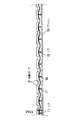
次に本発明の第5の実施形態について図13,図14を用いて説明する。図13は、記録装置の記録領域周辺の断面図、図14は、概略斜視図である。なお、第3の実施形態と同一の構成については同一の符号で示し説明を省略する。
【0062】
本実施形態では、図13に示すように、2つの排紙ローラユニット14,26が設けられている。すなわち、第3の実施形態と同様に、排紙ローラ12と、付勢ばね15によって排紙ローラ12に圧接され従動回転する拍車13とからなる排紙ローラユニット14が設けられており、本実施形態ではさらにその下流側に、2列目排紙ローラ25と、付勢ばね27によって2列目排紙ローラ25に圧接され従動回転する2列目拍車24とからなる2列目排紙ローラユニット26が設けられている。
【0063】
2列目排紙ローラユニット26の2列目拍車24および2列目排紙ローラ25も、排紙ローラユニット14と同じく、記録媒体7の搬送方向に沿ってリブ17、18と同一直線上に配置されている。従って、記録領域での緩やかな波打ち状態や、コックリングによる凹凸を変化させることはない。さらに、排紙ローラユニットが2列設けられているため、排紙される記録媒体7の先端(既に排紙ローラユニットの挟持部分から離脱した部分)が、その重みによって下方向に垂れるいわゆるおじぎをした状態となった場合でも、その記録媒体7の後端(記録領域内にとどまっている部分)が反動でプラテン側から記録ヘッド側に浮き上がろうとする動さを最小限にとどめることが可能となる。従って、記録媒体7の記録ヘッド1側への浮きをより防止することができる。
【0064】
また、図14に示すように、1列目の排紙ローラユニット14に比べ、2列目排紙ローラユニット26のローラおよび挟持部分の数を少なくしても良い。この場合には、隣り合うローラおよび挟持部分の間に、2列目排紙ローラ25よりも外径の小さいリング28を設けてもよい。リング28を設けることにより、2列目排紙ローラユニット26における記録媒体7の波打ち状態やコックリングによる凸部頂点位置を安定して保つことが可能である。なお、第4の実施形態と同様に、拍車を、搬送ローラの回転中心よりも回転中心が搬送方向上流にずれた位置に来るように配置してもよい。この場合、記録媒体7をリブ17、18に向けて押圧し記録ヘッド1側への浮き上がりをより確実に防止できる。
【0065】
以上説明したように、上述の第3〜第5の実施形態によれば、プラテン19にリブ17,18を搬送ローラユニット10による記録媒体7の挟持部分の延長線上に設けているので、記録媒体7の浮き上がりが抑制できる。
【0066】
さらに、プラテン19に長さの異なる2種類のリブ17,18を設け、それぞれの搬送方向上流側の始点を変えて交互に配置することにより、始点が下流側にあるリブ18に記録媒体7が押し付けられる力が増大し、紙浮き防止の効果がより確実になる。そして、この押圧力により、記録媒体7に、リブ17,18と当接する位置が凸状になり、リブ17,18間で凹状となる波打ち形状が予め形成されるので、記録媒体7に生じるコックリングは、凹部における変形量増大により吸収することができ、コックリングに起因して紙浮きが生じるおそれは小さい。
【0067】
また、搬送ローラユニット10の従動ローラ9を、搬送ローラ8に対して回転中心をずらして配置することにより、記録媒体7が搬送ローラユニット10から離れてもプラテン19に向かって押圧する力を維持し得るようにすることもできる。
【0068】
記録装置において使用される記録媒体7の一方の端部を揃える搬送基準位置50を設定し、他方の端部の1mm〜10mm内側にリブ17,18を設ける構成とすることにより、記録媒体7端部における浮き上がりを抑制することができる。さらに、リブ17,18の延長線上に下流側の排紙ローラユニット14の挟持部分が位置していると、浮き上がりの抑制がより確実になる。
【0069】
そして、記録媒体7の搬送方向に沿って、リブ17,18と同一直線上に排紙ローラユニット14の挟持部分を設けると、記録領域における記録媒体7の波打ち状態やコックリングによる凹凸を変化させることなく搬送することができる。
また、排紙ローラユニット14の拍車13を、排紙ローラ12に対して回転中心をずらして配置することにより、記録媒体7が搬送ローラユニット10から離れてもプラテン19に向かって押圧する力を維持し得るようにすることもできる。
【0070】
さらに、排紙ローラユニット14に加え、2列目排紙ローラーユニット26を設けることにより、記録媒体7の先端が垂れ下がっても、その記録媒体7の後端が反動で浮き上がろうとする動作を抑制することができる。
【0071】
このように記録媒体7のプラテン19からの浮きを抑えることができ、それに伴って記録媒体7と記録手段1との間隔を狭く設定することが可能になり、高品位記録が可能になる。
【0072】
【発明の効果】
以上説明したように、本発明によれば、プラテンにリブを搬送ローラユニットによる記録媒体の挟持部分の延長線上に設けているので、記録媒体の浮き上がりが抑制できる。
【0073】
さらに、プラテンに長さの異なる2種類のリブを設け、それぞれの搬送方向上流側の始点を変えて交互に配置することにより、始点が下流側にあるリブに記録媒体が押し付けられる力が増大し、紙浮き防止の効果がより確実になる。そして、この押圧力により、記録媒体に、リブと当接する位置が凸状になり、リブ間で凹状となる波打ち形状が予め形成されるので、記録媒体に生じるコックリングは、凹部における変形量増大により吸収することができ、コックリングに起因して紙浮きが生じるおそれは小さい。さらに、波状に変形した記録媒体は搬送方向に変形し難いため、排紙ローラ対によってプラテンへ記録媒体を押しつけても記録媒体の後端に紙浮きが発生し難い。
【0074】
また、搬送ローラユニットの従動ローラを、搬送ローラに対して回転中心をずらして配置することにより、記録媒体が搬送ローラユニットから離れてもプラテンに向かって押圧する力を維持し得るようにすることもできる。
【0075】
記録装置において使用される記録媒体の一方の端部を揃える搬送基準位置を設定し、他方の端部の1mm〜10mm内側にリブを設ける構成とすることにより、記録媒体端部における浮き上がりを抑制することができる。さらに、リブの延長線上に下流側の排紙ローラユニットの挟持部分が位置していると、浮き上がりの抑制がより確実になる。
【0076】
そして、記録媒体の搬送方向に沿って、リブと同一直線上に排紙ローラユニットの挟持部分を設けると、記録領域における記録媒体の波打ち状態やコックリングによる凹凸を変化させることなく搬送することができる。
【0077】
また、排紙ローラユニットの拍車を、排紙ローラに対して回転中心をずらして配置することにより、記録媒体が搬送ローラユニットから離れてもプラテンに向かって押圧する力を維持し得るようにすることもできる。
【0078】
さらに、排紙ローラユニットを2列設けることにより、記録媒体の先端が垂れ下がっても、その記録媒体の後端が反動で浮き上がろうとする動作を抑制することができる。
【0079】
このように記録媒体のプラテンからの浮きを抑えることができ、それに伴って記録媒体と記録手段との間隔を狭く設定することが可能になり、高品位記録が可能になる。
【0080】
また、部品点数を増やすことなく紙浮きを抑制できるので、コスト的にも有効である。
【図面の簡単な説明】
【図1】本発明の第1の実施形態に係る記録装置の記録手段の周辺部の断面図である。
【図2】第1の実施形態に係る記録装置の記録手段の周辺部の概略斜視図である。
【図3】図1の矢印A方向に見た図であり、記録動作前の記録媒体の状態を示す概略図である。
【図4】図1の矢印A方向に見た図であり、記録動作後の記録媒体の状態を示す概略図である。
【図5】第2の実施形態に係る記録装置の記録手段の周辺部の概略斜視図である。
【図6】本発明の第3の実施形態の記録領域周辺の断面図である。
【図7】第3の実施形態の記録領域周辺の概略斜視図である。
【図8】記録前の記録媒体が長いリブにのみ当接した状態を示す、図6の矢印A方向に見た概略図である。
【図9】記録前の記録媒体が短いリブにも当接した状態を示す、図6の矢印A方向に見た概略図である。
【図10】記録後の記録媒体にコックリングが発生した状態を示す、図6の矢印A方向に見た概略図である。
【図11】第3の実施形態の記録領域周辺の平面図である。
【図12】第4の実施形態の記録領域周辺の断面図である。
【図13】第5の実施形態の記録領域周辺の断面図である。
【図14】第5の実施形態の記録領域周辺の概略斜視図である。
【符号の説明】
1 記録ヘッド(記録手段)
2 キャリッジ
3 ガイドレール
4 ガイドコロ
5 支持レール
6 タイミングベルト
7 記録媒体(普通紙)
8 搬送ローラ
9 従動ローラ
9’ 従動ローラユニット
10 搬送ローラユニット
11 付勢ばね
12 排紙ローラ
13 拍車
14 排紙ローラユニット
15 付勢ばね
17 リブ
18 リブ
19 プラテン
20 軸
21 拍車
22 排紙ローラ
23 排紙ローラユニット
24 2列目拍車
25 2列目排紙ローラ
26 2列目排紙ローラユニット
27 付勢ばね
28 リング
50 搬送基準位置[0001]
BACKGROUND OF THE INVENTION
The present invention relates to a recording apparatus that records an image such as a character, a figure, or a pattern by attaching ink to a recording medium using a recording unit.
[0002]
[Prior art]
When recording is performed with ink droplets attached to the recording medium, the recording medium swells at this portion when the ink is absorbed by the recording medium. At this time, due to the difference in density of the ink adhering to the recording medium, a portion having a difference in expansion and contraction occurs, and the greatly extended portion bends in a direction perpendicular to the recording surface of the sheet-like recording medium, so-called cockling. Unevenness occurs. At this time, as the time passes, the ink droplets are absorbed and swelled by the recording medium, and the unevenness generated becomes larger. When recording image data, etc., the feed pitch is reduced by reducing the feed pitch of the print medium, dividing the image data at random, and increasing the number of scans of the carriage that moves by placing the print means. Although a method of reducing the influence on the recording quality due to the unevenness of the recording has been adopted, when the feed pitch is small as described above, the recording time becomes long and the cockling becomes large. For this reason, during the recording operation, the recording medium bends from the platen side that supports the recording medium at a position facing the recording means toward the recording means, and the paper floats. As a result, the recording means and the recording medium May be rubbed in contact with each other, and the quality of the image may be impaired.
[0003]
In an ink jet recording type recording apparatus that performs recording by ejecting ink, the shorter the flight path of the ejected ink, the higher the accuracy of the ink adhesion position. Therefore, in this recording apparatus, in order to obtain a clear and high-quality recording result, it is required to set the distance between the recording surface of the recording medium and the recording head (hereinafter referred to as “head gap”) as narrow as possible. . On the other hand, when the head gap is narrowed, rubbing between the recording means and the recording medium is likely to occur.
[0004]
Therefore, there is a demand for a method for reducing the paper floating due to cockling so that the recording means and the recording medium are not rubbed even if the head gap is narrowed.
[0005]
Japanese Patent Laid-Open No. 61-95966 and Japanese Patent Laid-Open No. 3-29359 have a configuration in which a plurality of small holes are provided in the platen as a configuration for preventing paper floating from the platen of the recording medium. A configuration (first conventional example) is disclosed in which a suction force is applied to a recording medium through a small hole and the recording medium is brought into close contact with the platen.
[0006]
Japanese Patent Laid-Open No. 4-69264 discloses a mechanism (second conventional example) for pressing a recording medium against a platen side by a paper pressing member on the upstream side in the conveyance direction of the recording medium.
[0007]
Further, Japanese Patent Application Laid-Open No. 9-48161 discloses that a plurality of ribs extending in the recording medium conveyance direction are arranged on a flat platen in a direction intersecting the conveyance direction, and the leading ends of the ribs are located upstream of the ribs. An ink jet recording apparatus (third conventional example) is disclosed in which a pressing plate that sandwiches a recording medium together with a portion extends in a direction crossing the transport direction. Further, in this ink jet recording apparatus, a protrusion for urging the recording medium is provided below the portion of the presser plate corresponding to between the ribs.
[0008]
[Problems to be solved by the invention]
In the first conventional example described above, a negative pressure generating means is necessary, and the apparatus becomes large and the cost is increased. And there is a problem that noise during intake and exhaust is large. Also, when recording on a small-sized recording medium, if even a part of the plurality of small holes provided in the platen is opened outside the recording medium, the suction efficiency is remarkably lowered and the reliability is improved. Become scarce. If all the small holes are always covered with the recording medium, the suction force cannot be exerted on the entire recording medium, and the reliability is poor. In order to solve this, when using a recording medium of a small size, a means for closing the small hole located outside the recording medium is required, and the configuration becomes considerably complicated and expensive.
[0009]
In the second conventional example, when the recording area is large, there is a possibility that the recording medium is not sufficiently adhered to the platen. That is, with this configuration, the recording medium is pressed toward the platen by the paper pressing member on the upstream side and is sandwiched by the paper discharge roller or the like on the downstream side, but in the recording area between the two, the recording medium is directed toward the platen. It will not be pressed. Therefore, if the recording width of one line of the recording head is wide and the recording area is wide, the recording medium floats from the platen in the essential recording area simply by pressing with the upstream paper pressing member and the downstream discharge roller. There is a risk of wrinkling or wrinkling on the recording medium. Furthermore, if the clamping portion of the pair of paper discharge rollers is made lower than the recording medium guide surface of the platen in order to suppress the paper floating, the rear end of the recording medium is lifted after the recording sheet is separated from the paper pressing member. There is.
[0010]
In the third conventional example, a paper presser plate is disposed on the upstream side of the rib at a position almost in contact with the front end of the rib, but the recording medium is held between the front end of the rib and the paper presser plate. The recording medium cannot be urged toward the platen side. In addition, the protrusion provided on the lower surface of the paper pressing plate upstream of the gap between the adjacent ribs has an effect of urging the recording medium positioned between the ribs in the platen direction. When a relatively high-stiff recording medium is transported or when recording is performed on a wide recording area, there is a problem that it is not possible to completely prevent the recording medium from floating from the platen.
[0011]
SUMMARY OF THE INVENTION Accordingly, an object of the present invention is to provide an ink jet recording apparatus that can solve the above-described problems with a low cost and simple configuration and prevent the recording medium from being lifted to the recording means side.
[0012]
Another object of the present invention is to provide an ink jet recording apparatus that performs recording by attaching ink droplets to a recording medium using an ink jet recording means.
A platen for supporting the recording medium at a position facing the ink jet recording means;
A plurality of conveying roller pairs for nipping and conveying the recording medium at a position where ink is attached to the recording medium by the inkjet recording means;
A plurality of projections extending in the recording medium conveyance direction with respect to the platen and arranged in parallel in a direction crossing the recording medium conveyance direction to support the back side of the recording medium. An object of the present invention is to provide an ink jet recording apparatus in which a pair of conveying rollers is positioned on an upstream extension line.
[0013]
Still another object of the present invention is to provide a conveying roller unit provided with a plurality of pairs of rollers disposed on the upstream side of the recording area, and a position disposed on the downstream side of the conveying roller unit and facing the recording means. In an inkjet recording apparatus having a platen that supports a recording medium,
A conveyance roller unit includes a clamping unit that clamps a recording medium by a plurality of pairs of rollers, and a non-clamping unit.
A plurality of ribs provided on the platen, located on an extension line of the sandwiching portion along the recording medium conveyance direction, and extending along the recording medium conveyance direction;
A transport reference position where one end of the recording medium is aligned regardless of the size of the recording medium,
Another object of the present invention is to provide an ink jet recording apparatus in which one of the plurality of ribs is disposed so as to be located 1 mm to 10 mm inside from the other end of the recording medium having a fixed size.
[0014]
[Means for Solving the Problems]
In order to solve the above problems, an ink jet recording apparatus according to the present invention is an ink jet recording apparatus that performs recording by attaching ink droplets to a recording medium using an ink jet recording means.
A platen for supporting the recording medium at a position facing the ink jet recording means;
A plurality of conveying roller pairs for nipping and conveying the recording medium at a position where ink is attached to the recording medium by the inkjet recording means;
A plurality of projections extending in the recording medium conveyance direction with respect to the platen and arranged in parallel in a direction crossing the recording medium conveyance direction to support the back side of the recording medium. The conveyance roller pair is located on the upstream extension line.
[0015]
According to this configuration, the recording medium can be held so that the recording medium does not float on the platen with the back side in contact with the protrusion. In particular, when swelling occurs in the recording medium, the recording medium bends toward the platen between adjacent ribs and deforms in a wave shape in a direction perpendicular to the conveying direction. When the recording medium is deformed in this way, it is difficult to deform in a direction parallel to the transport direction. In addition, deformation due to swelling in a direction perpendicular to the conveying direction is absorbed by an increase in bending between the ribs. Therefore, it is possible to suppress the occurrence of paper floating due to deformation so that the recording medium approaches the ink jet recording means side.
[0016]
If the plurality of protrusions includes a protrusion having a different position at the upstream end portion in the conveyance direction of the recording medium, the protrusion portion with the end portion located on the downstream side further increases the contact position of the recording medium with the platen. By being on the downstream side, the force for pressing the recording medium against the platen by the conveying roller pair can also be applied to the downstream side.
[0017]
In this way, if the protrusions having different positions of the upstream end of the recording medium in the transport direction are provided so that the upstream end of the transport direction is upstream and the other end are alternately arranged in parallel. Further, the force for pressing the recording medium against the platen by the pair of conveying rollers can be distributed substantially evenly over the direction perpendicular to the conveying direction so as to act efficiently.
[0018]
In the present invention, the conveyance roller pair is disposed on the downstream side in the recording medium conveyance direction from the roller facing the roller contacting the ink droplet adhesion surface side of the recording medium.In a shifted positionIf configured to be arranged, the recording medium can be nipped and conveyed so as to be effectively pressed against the plurality of protrusions, and the pressing force can be further applied to the downstream side.
[0019]
In addition, the ink jet recording apparatus according to the present invention is disposed upstream of the recording area, and includes a transport roller unit including a plurality of pairs of rollers, and is disposed downstream of the transport roller unit and records at a position facing the recording unit. A platen that supports the medium and,In an inkjet recording apparatus having
Transport roller unitArrangedA sandwiching portion for sandwiching the recording medium by a plurality of pairs of rollers, and a non- sandwiching portion,
On the platenArranged, On the extension line of the clamping part along the recording medium conveyance directionBecauseA plurality of ribs extending along the recording medium conveyance direction;
RecordA transport reference position where one end of the recording medium is aligned, andHave,
One of the plurality of ribs is disposed so as to be located 1 mm to 10 mm inside from the other end of the standard-sized recording medium.
[0020]
According to this configuration, both the end portion on which the recording medium conveyance reference position is set and the other end portion are lifted at the end portion of the recording medium, with the ribs located near the end portions inside the respective end portions as fulcrums. Can be suppressed.
[0021]
A paper discharge roller unit that conveys the recording medium is provided on the downstream side of the recording area, and the paper discharge roller unit has a sandwiching portion that sandwiches the recording medium by at least one pair of rollers, and a non-nip portion.TheHolding partIsIt is good also as a structure located on the substantially extended line of a rib along a recording medium conveyance direction. In this case, even if the leading edge of the recording medium hangs down, the movement of the trailing edge of the recording medium trying to lift up due to the reaction can be suppressed.
[0022]
Two rows of paper discharge roller units may be arranged. And, ExhaustPaper roller unitIsIf the downstream discharge roller unit has a smaller number of rollers than the upstream discharge roller unit, the configuration is simplified.
[0023]
The paper discharge roller unit includes a paper discharge roller and a driven roller having a rotation center at a position shifted upstream from the rotation center of the paper discharge roller and pressing the recording medium toward the paper discharge roller and the platen. Even when the recording medium is separated from the transport roller unit, the pressing force toward the platen can be maintained.
[0024]
The paper discharge roller isCrossingIt may be divided into a plurality of pieces in the direction to be performed.
[0025]
In the ink jet recording apparatus according to the present invention, since the paper floating of the recording medium is small, the distance between the recording means and the platen (head gap) can be reduced. Therefore, when the present invention is applied to a recording apparatus having an ink jet recording type recording means for ejecting ink and adhering to a recording medium, a high-quality recording apparatus having a small head gap and high accuracy of the position where the ejected ink is adhered can be obtained. can do.
[0026]
DETAILED DESCRIPTION OF THE INVENTION
Embodiments of the present invention will be described below with reference to the drawings.
[0027]
[First Embodiment]
FIG. 1 shows a cross-sectional view of a recording area peripheral portion of the recording apparatus according to the first embodiment of the present invention, and FIG. 2 shows a schematic perspective view thereof.
[0028]
As shown in FIG. 1, the recording apparatus of the present embodiment includes an ink jet recording type recording head 1 that records an image or the like by ejecting and adhering ink toward a recording medium.
[0029]
First, the scanning mechanism of the recording means will be described. The recording head 1 is detachably mounted on the carriage 2. The carriage 2 is slidably supported on the guide rail 3, and a
[0030]
Next, the transport mechanism for the
[0031]
The
[0032]
On the downstream side of the recording head 1 in the conveyance path, a
[0033]
Next, a recording operation by this recording apparatus will be described.
[0034]
The
[0035]
Next, the behavior of the
[0036]
The
[0037]
Next, when the recording ink using water as a main solvent is attached to the
[0038]
According to the present embodiment, since paper floating can be suppressed, the interval (head gap) between the recording head 1 and the
[0039]
[Second Embodiment]
A recording apparatus according to the second embodiment will be described with reference to FIG. In FIG. 5, the same parts as those in the first embodiment are denoted by the same reference numerals and the description thereof is omitted.
[0040]
In FIG. 5, the conveyance roller pair 10 is constituted by a
[0041]
As described above, by using a driven
[0042]
As described above, according to the first and second embodiments described above, the
[0043]
In addition, paper floating can be suppressed without increasing the number of parts, which is also effective in terms of cost.
[0044]
[Third Embodiment]
A recording apparatus according to a third embodiment of the present invention will be described. FIG. 6 shows a sectional view of the periphery of the recording area, and FIG. 7 shows a schematic perspective view thereof.
[0045]
The difference between the first and second embodiments described above and the third to fifth embodiments is that, in addition to the
[0046]
First, the configuration near the recording area will be described. As shown in FIGS. 6 and 7, a
[0047]
On the downstream side of the recording area by the recording head 1, the
[0048]
Next, a recording operation in this recording apparatus will be described. When the
[0049]
In the recording area, the carriage 2 scans along the guide rail 3 and the
[0050]
When the leading edge of the
[0051]
As described above, when the recording on the entire surface of the
[0052]
Next, the behavior of the
[0053]
As shown in FIGS. 7 and 8, the rotation center of the driven
[0054]
Further, when the plain paper is conveyed, the concave portion between the ribs 17 (the leading end of the plain paper 7) is pushed up against the
[0055]
When ink using water as a main solvent adheres to the
[0056]
Then, the
[0057]
In a normal recording apparatus, the size of a recording medium (recording paper) to be used is determined to some extent in advance. For example, it is assumed that a general printer or the like uses, for example, a postcard, B5 size, A4 LTR (letter size), B4 size, LDR (leisure size), or A3 size recording medium. Therefore, in the present embodiment, the
[0058]
According to such a configuration, the side end portion of the
[0059]
[Fourth Embodiment]
Next, a fourth embodiment of the present invention will be described with reference to FIG. FIG. 12 is a cross-sectional view around the recording area of the recording apparatus. In addition, about the structure same as 3rd Embodiment, it shows with the same code | symbol and abbreviate | omits description.
[0060]
In the third embodiment, as shown in FIG. 6, the rotation center of the
[0061]
[Fifth Embodiment]
Next, a fifth embodiment of the present invention will be described with reference to FIGS. 13 is a cross-sectional view around the recording area of the recording apparatus, and FIG. 14 is a schematic perspective view. In addition, about the structure same as 3rd Embodiment, it shows with the same code | symbol and abbreviate | omits description.
[0062]
In the present embodiment, as shown in FIG. 13, two paper discharge roller units 14 and 26 are provided. That is, similarly to the third embodiment, a paper discharge roller unit 14 including a
[0063]
The second row spur 24 and the second row discharge roller 25 of the second row discharge roller unit 26 are also collinear with the
[0064]
Further, as shown in FIG. 14, the number of rollers and nipping portions of the second row paper discharge roller unit 26 may be reduced as compared with the first row paper discharge roller unit 14. In this case, a ring 28 having an outer diameter smaller than that of the second row paper discharge roller 25 may be provided between the adjacent rollers and the sandwiching portion. By providing the ring 28, it is possible to stably maintain the undulation state of the
[0065]
As described above, according to the above-described third to fifth embodiments, the
[0066]
Further, two types of
[0067]
Further, by disposing the driven
[0068]
By setting the
[0069]
Then, when the holding portion of the paper discharge roller unit 14 is provided on the same straight line as the
Further, by arranging the
[0070]
Further, by providing the second-line discharge roller unit 26 in addition to the discharge roller unit 14, even if the leading end of the
[0071]
In this way, the floating of the
[0072]
【The invention's effect】
As described above, according to the present invention, since the rib is provided on the platen on the extension line of the recording medium holding portion by the transport roller unit, the lifting of the recording medium can be suppressed.
[0073]
Furthermore, two types of ribs with different lengths are provided on the platen, and the starting point on the upstream side in the transport direction is changed and arranged alternately, thereby increasing the force with which the recording medium is pressed against the rib whose starting point is on the downstream side. In addition, the effect of preventing paper floating is more certain. Then, this pressing force makes the recording medium come into contact with the rib in a convex shape, and a corrugation shape that is concave between the ribs is formed in advance, so that cockling generated in the recording medium increases the deformation amount in the concave portion. Therefore, there is little risk of paper floating due to cockling. Further, since the recording medium deformed in a wave shape is difficult to be deformed in the transport direction, even if the recording medium is pressed against the platen by the pair of paper discharge rollers, the paper does not easily float at the rear end of the recording medium.
[0074]
In addition, the driven roller of the transport roller unit is arranged with the rotation center shifted from the transport roller so that the pressing force toward the platen can be maintained even when the recording medium is separated from the transport roller unit. You can also.
[0075]
By setting a conveyance reference position for aligning one end of a recording medium used in the recording apparatus and providing a rib inside 1 mm to 10 mm of the other end, lifting at the end of the recording medium is suppressed. be able to. Further, if the sandwiching portion of the downstream discharge roller unit is located on the extended line of the rib, the lifting is more reliably suppressed.
[0076]
Then, if the holding portion of the paper discharge roller unit is provided on the same straight line as the rib along the conveyance direction of the recording medium, the recording medium can be conveyed without changing the wavy state of the recording medium and the unevenness due to cockling. it can.
[0077]
Further, the spur of the paper discharge roller unit is arranged with the rotation center shifted from the paper discharge roller, so that the pressing force toward the platen can be maintained even when the recording medium is separated from the transport roller unit. You can also.
[0078]
Further, by providing two rows of paper discharge roller units, even if the leading edge of the recording medium hangs down, it is possible to suppress an operation in which the trailing edge of the recording medium tends to float due to a reaction.
[0079]
Thus, the floating of the recording medium from the platen can be suppressed, and accordingly, the interval between the recording medium and the recording means can be set narrow, and high-quality recording can be performed.
[0080]
In addition, paper floating can be suppressed without increasing the number of parts, which is also effective in terms of cost.
[Brief description of the drawings]
FIG. 1 is a cross-sectional view of a peripheral portion of a recording unit of a recording apparatus according to a first embodiment of the present invention.
FIG. 2 is a schematic perspective view of a peripheral portion of a recording unit of the recording apparatus according to the first embodiment.
FIG. 3 is a diagram viewed in the direction of arrow A in FIG. 1, and is a schematic diagram illustrating a state of a recording medium before a recording operation.
4 is a diagram viewed in the direction of arrow A in FIG. 1, and is a schematic diagram illustrating a state of a recording medium after a recording operation.
FIG. 5 is a schematic perspective view of a peripheral portion of a recording unit of a recording apparatus according to a second embodiment.
FIG. 6 is a sectional view around a recording area according to a third embodiment of the present invention.
FIG. 7 is a schematic perspective view around a recording area according to a third embodiment.
FIG. 8 is a schematic view seen in the direction of arrow A in FIG. 6, showing a state in which the recording medium before recording is in contact with only a long rib.
9 is a schematic view seen in the direction of arrow A in FIG. 6, showing a state in which the recording medium before recording is in contact with a short rib.
10 is a schematic view seen in the direction of arrow A in FIG. 6, showing a state in which cockling has occurred in the recording medium after recording.
FIG. 11 is a plan view around a recording area according to a third embodiment.
FIG. 12 is a cross-sectional view around a recording area according to a fourth embodiment.
FIG. 13 is a cross-sectional view around a recording area according to a fifth embodiment.
FIG. 14 is a schematic perspective view around a recording area according to a fifth embodiment.
[Explanation of symbols]
1 Recording head (recording means)
2 Carriage
3 Guide rail
4 Guide rollers
5 Support rail
6 Timing belt
7 Recording media (plain paper)
8 Transport roller
9 Followed roller
9 'driven roller unit
10 Transport roller unit
11 Biasing spring
12 Paper discharge roller
13 Spur
14 Paper discharge roller unit
15 Biasing spring
17 Ribs
18 Ribs
19 Platen
20 axes
21 Spur
22 Paper discharge roller
23 Paper discharge roller unit
24 Second row spur
25 Second row paper discharge roller
26 Second row paper discharge roller unit
27 Biasing spring
28 rings
50 Transport reference position
Claims (14)
前記記録媒体を前記インクジェット記録手段と対向する位置に支持するプラテンと、
前記インクジェット記録手段により前記記録媒体にインクが付着される位置に当該記録媒体を挟持して搬送する複数の搬送ローラ対と、
前記プラテンに対して前記記録媒体の搬送方向に延在するとともに前記記録媒体の搬送方向と交差する方向に複数並設されて前記記録媒体の裏面側を支持する突起とを含み、該突起夫々の前記記録媒体搬送方向上流側延長線上には、前記搬送ローラ対が位置することを特徴とするインクジェット記録装置。In an inkjet recording apparatus that performs recording by attaching ink droplets to a recording medium using an inkjet recording means,
A platen for supporting the recording medium at a position facing the inkjet recording means;
A plurality of conveyance roller pairs for nipping and conveying the recording medium at a position where ink is attached to the recording medium by the inkjet recording means;
A plurality of protrusions that extend in the transport direction of the recording medium with respect to the platen and that are arranged in parallel in a direction intersecting the transport direction of the recording medium and support the back side of the recording medium. wherein the recording medium body conveyance direction upstream side extension on an ink jet recording apparatus characterized by the conveying roller pair is located.
前記搬送ローラユニットに配され、複数対の前記ローラにより前記記録媒体を挟持する挟持部と、非挟持部と、
前記プラテンに配され、前記記録媒体搬送方向に沿って前記挟持部の延長線上であって、前記記録媒体搬送方向に沿って延びる複数のリブと、
前記記録媒体の一方の端部が揃えられる搬送基準位置と、を有し、
前記複数のリブのうちの一つが、定形サイズの記録媒体の他方の端部から1mm〜10mm内側に位置するように配設されていることを特徴とするインクジェット記録装置。Is disposed upstream of the recording area has a conveying roller unit having a plurality of pairs of rollers, the arranged downstream of the conveying roller unit, and the platen for supporting the recording medium at a position facing the recording means, the In an inkjet recording apparatus,
A sandwiching portion disposed in the transport roller unit and sandwiching the recording medium by a plurality of pairs of the rollers ;
Disposed in said platen, said a extension of holding portions along the recording medium conveying direction, and a plurality of ribs extending along the recording medium conveying direction,
Before SL has a first end transport reference position aligns the recording medium, and
An ink jet recording apparatus, wherein one of the plurality of ribs is disposed so as to be located 1 mm to 10 mm inside from the other end of the recording medium having a fixed size.
前記排紙ローラユニットが、少なくとも1対のローラにより前記記録媒体を挟持する挟持部と、非挟持部とを有し、前記挟持部が前記記録媒体搬送方向に沿って前記リブの延長線上に位置している請求項6〜8のいずれか1項に記載のインクジェット記録装置。A paper discharge roller unit for conveying the recording medium is provided on the downstream side of the recording area,
The discharge roller unit, and a clamping portion for clamping the recording medium by at least one pair of rollers, the non-pinching unit and has a front Kikyoji portion front type recording medium along a conveying direction on the extension of the rib The ink jet recording apparatus according to claim 6, wherein the ink jet recording apparatus is located in the ink jet recording apparatus.
Priority Applications (4)
| Application Number | Priority Date | Filing Date | Title |
|---|---|---|---|
| JP2000051579A JP4194205B2 (en) | 1999-05-14 | 2000-02-28 | Inkjet recording device |
| US09/517,506 US6659603B2 (en) | 1999-05-14 | 2000-03-02 | Ink jet recording method and apparatus having platen with extrusions positioned in one-to-one correspondence with roller nips |
| EP00104790A EP1053883B1 (en) | 1999-05-14 | 2000-03-06 | Ink jet recording apparatus |
| DE60015009T DE60015009T2 (en) | 1999-05-14 | 2000-03-06 | Ink jet recording apparatus |
Applications Claiming Priority (5)
| Application Number | Priority Date | Filing Date | Title |
|---|---|---|---|
| JP11-134205 | 1999-05-14 | ||
| JP13420599 | 1999-05-14 | ||
| JP13420799 | 1999-05-14 | ||
| JP11-134207 | 1999-05-14 | ||
| JP2000051579A JP4194205B2 (en) | 1999-05-14 | 2000-02-28 | Inkjet recording device |
Publications (3)
| Publication Number | Publication Date |
|---|---|
| JP2001031288A JP2001031288A (en) | 2001-02-06 |
| JP2001031288A5 JP2001031288A5 (en) | 2007-02-08 |
| JP4194205B2 true JP4194205B2 (en) | 2008-12-10 |
Family
ID=27316847
Family Applications (1)
| Application Number | Title | Priority Date | Filing Date |
|---|---|---|---|
| JP2000051579A Expired - Fee Related JP4194205B2 (en) | 1999-05-14 | 2000-02-28 | Inkjet recording device |
Country Status (4)
| Country | Link |
|---|---|
| US (1) | US6659603B2 (en) |
| EP (1) | EP1053883B1 (en) |
| JP (1) | JP4194205B2 (en) |
| DE (1) | DE60015009T2 (en) |
Cited By (1)
| Publication number | Priority date | Publication date | Assignee | Title |
|---|---|---|---|---|
| JP7202974B2 (en) | 2019-06-03 | 2023-01-12 | 東日本旅客鉄道株式会社 | Soundproof panel fixing device and soundproof panel fixing method |
Families Citing this family (43)
| Publication number | Priority date | Publication date | Assignee | Title |
|---|---|---|---|---|
| US6971811B2 (en) * | 2002-07-25 | 2005-12-06 | Silverbrook Research Pty Ltd | Print engine having a pair of feed rollers and a print zone proximal thereto |
| US20020144770A1 (en) * | 2001-04-06 | 2002-10-10 | Stephane Mabit | Carrier-less patch protection including cassette and separation process |
| US6712463B2 (en) * | 2001-09-07 | 2004-03-30 | Canon Kabushiki Kaisha | Recording apparatus |
| US6869176B2 (en) | 2001-09-07 | 2005-03-22 | Canon Kabushiki Kaisha | Recording apparatus, and recording medium floating prevention member |
| JP2003292224A (en) | 2002-01-31 | 2003-10-15 | Seiko Epson Corp | Ink-jet type recording device and delivery device |
| JP4073008B2 (en) | 2002-09-17 | 2008-04-09 | キヤノン株式会社 | Recording device |
| KR100472479B1 (en) * | 2002-10-31 | 2005-03-08 | 삼성전자주식회사 | Paper guide of ink jet printer and inkjet printer having thereof |
| JP2004203526A (en) * | 2002-12-24 | 2004-07-22 | Sharp Corp | Recording device |
| JP4013909B2 (en) * | 2003-04-10 | 2007-11-28 | セイコーエプソン株式会社 | Liquid ejector |
| JP3694006B2 (en) * | 2003-05-21 | 2005-09-14 | シャープ株式会社 | Inkjet printer |
| JP2005047227A (en) * | 2003-07-31 | 2005-02-24 | Canon Inc | Double-sided recording device |
| JP4719409B2 (en) * | 2003-08-29 | 2011-07-06 | キヤノン株式会社 | Recording method |
| JP2005082373A (en) * | 2003-09-10 | 2005-03-31 | Sharp Corp | Ink jet printer |
| TW200540018A (en) * | 2004-06-09 | 2005-12-16 | Benq Corp | Print system with upgrading print quality |
| JP2006103278A (en) * | 2004-10-08 | 2006-04-20 | Canon Inc | Recorder |
| US7673985B2 (en) * | 2005-05-25 | 2010-03-09 | Brother Kogyo Kabushiki Kaisha | Ink-jet recording apparatus provided with platen and movable support section for supporting recording paper |
| US7811016B2 (en) * | 2005-05-25 | 2010-10-12 | Agfa Graphics Nv | Flatbed printing machine |
| EP1803574B1 (en) * | 2005-12-27 | 2012-09-19 | Brother Kogyo Kabushiki Kaisha | Inkjet recording device and driving unit provided therein |
| US8157368B2 (en) * | 2006-01-31 | 2012-04-17 | Brother Kogyo Kabushiki Kaisha | Ink jet recording device and method of conveying recording medium in the same |
| JP5194671B2 (en) * | 2007-09-25 | 2013-05-08 | セイコーエプソン株式会社 | Recording device |
| JP2009256098A (en) * | 2008-03-19 | 2009-11-05 | Seiko Epson Corp | Fluid injection device |
| JP2010143123A (en) * | 2008-12-19 | 2010-07-01 | Canon Inc | Recording device and recording method |
| JP2010149478A (en) * | 2008-12-26 | 2010-07-08 | Seiko Epson Corp | Recording medium and recorder |
| JP5293325B2 (en) * | 2009-03-25 | 2013-09-18 | セイコーエプソン株式会社 | Recording apparatus and conveying method |
| JP5338424B2 (en) | 2009-03-25 | 2013-11-13 | セイコーエプソン株式会社 | Recording apparatus and conveying method |
| JP4873084B2 (en) * | 2010-01-25 | 2012-02-08 | ブラザー工業株式会社 | Inkjet recording device |
| TW201208895A (en) * | 2010-05-17 | 2012-03-01 | Silverbrook Res Pty Ltd | System for transporting media in printer |
| CN102407684B (en) * | 2010-09-10 | 2014-07-30 | 精工爱普生株式会社 | Paper conveyance device and printer |
| JP5287830B2 (en) * | 2010-10-29 | 2013-09-11 | ブラザー工業株式会社 | Inkjet recording device |
| JP5700205B2 (en) * | 2011-02-08 | 2015-04-15 | セイコーエプソン株式会社 | Recording device |
| JP2012254608A (en) * | 2011-06-10 | 2012-12-27 | Mimaki Engineering Co Ltd | Medium processing device |
| JP5942570B2 (en) | 2011-11-28 | 2016-06-29 | ブラザー工業株式会社 | Inkjet recording device |
| US8967796B2 (en) | 2011-11-28 | 2015-03-03 | Brother Kogyo Kabushiki Kaisha | Inkjet recording apparatus |
| JP5924221B2 (en) * | 2012-09-28 | 2016-05-25 | ブラザー工業株式会社 | Conveying apparatus and inkjet recording apparatus |
| US9045299B2 (en) * | 2013-02-18 | 2015-06-02 | Lexmark International, Inc. | Star wheel with adjustable directional biaser |
| JP2014162631A (en) * | 2013-02-27 | 2014-09-08 | Katsuragawa Electric Co Ltd | Discharge mechanism of medium |
| JP5705291B2 (en) * | 2013-11-08 | 2015-04-22 | キヤノン株式会社 | Recording device |
| JP6547482B2 (en) | 2015-07-21 | 2019-07-24 | セイコーエプソン株式会社 | Liquid discharge device |
| WO2017130302A1 (en) * | 2016-01-26 | 2017-08-03 | 富士通フロンテック株式会社 | Paper sheet conveying mechanism and paper sheet handling device |
| JP6919341B2 (en) | 2017-05-31 | 2021-08-18 | セイコーエプソン株式会社 | Recording device |
| JP7094680B2 (en) * | 2017-09-29 | 2022-07-04 | キヤノン株式会社 | Image forming device |
| JP6515165B2 (en) * | 2017-10-13 | 2019-05-15 | シャープ株式会社 | Paper conveying apparatus and image forming apparatus provided with the same |
| JP6735874B2 (en) * | 2019-04-15 | 2020-08-05 | シャープ株式会社 | Paper transport device and image forming apparatus including the same |
Family Cites Families (19)
| Publication number | Priority date | Publication date | Assignee | Title |
|---|---|---|---|---|
| JPS6195966A (en) | 1984-10-18 | 1986-05-14 | Nec Corp | Preventing mechanism for floating of printing paper |
| JPH0469264A (en) | 1990-07-10 | 1992-03-04 | Nec Data Terminal Ltd | Holding mechanism for sheet of ink jet printer |
| US5326011A (en) * | 1993-01-22 | 1994-07-05 | Printware, Inc. | Reduced-skew web drive between rollers of differing coefficients of friction, particularly to transport paper, metal or film in a laser imager |
| ATE209573T1 (en) | 1993-07-28 | 2001-12-15 | Canon Kk | INKJET RECORDING APPARATUS AND INKJET RECORDING METHOD |
| JP2718626B2 (en) | 1993-11-16 | 1998-02-25 | キヤノン株式会社 | Sheet material transport device |
| SG46614A1 (en) | 1994-02-10 | 1998-02-20 | Seiko Epson Corp | Ink jet printer |
| JP3432052B2 (en) | 1994-09-02 | 2003-07-28 | キヤノン株式会社 | Ink jet recording device |
| US5847719A (en) * | 1995-02-21 | 1998-12-08 | Canon Kabushiki Kaisha | Recording apparatus |
| JP3376148B2 (en) | 1995-02-21 | 2003-02-10 | キヤノン株式会社 | Recording device having image reading function |
| JP3259592B2 (en) | 1995-04-21 | 2002-02-25 | セイコーエプソン株式会社 | Inkjet printer |
| US6027211A (en) * | 1995-07-14 | 2000-02-22 | Canon Kabushiki Kaisha | Sheet feeding apparatus and recording apparatus |
| JP3841315B2 (en) | 1995-12-26 | 2006-11-01 | キヤノン株式会社 | Printing apparatus and printing method used in the apparatus |
| DE69718768T2 (en) * | 1996-03-04 | 2003-10-16 | Copyer Co | IMAGING DEVICE |
| JPH1016350A (en) * | 1996-03-14 | 1998-01-20 | Canon Inc | Printer |
| JP3372800B2 (en) * | 1996-12-06 | 2003-02-04 | キヤノン株式会社 | Recording device |
| US6089773A (en) | 1997-12-12 | 2000-07-18 | Lexmark International, Inc. | Print media feed system for an ink jet printer |
| US6113289A (en) * | 1998-01-05 | 2000-09-05 | Seiko Epson Corporation | Dot recording device |
| JP3762155B2 (en) * | 1999-08-20 | 2006-04-05 | キヤノン株式会社 | Paper discharge device and image forming apparatus having the same |
| JP4522015B2 (en) * | 2001-05-10 | 2010-08-11 | キヤノン株式会社 | Recording device |
-
2000
- 2000-02-28 JP JP2000051579A patent/JP4194205B2/en not_active Expired - Fee Related
- 2000-03-02 US US09/517,506 patent/US6659603B2/en not_active Expired - Fee Related
- 2000-03-06 DE DE60015009T patent/DE60015009T2/en not_active Expired - Lifetime
- 2000-03-06 EP EP00104790A patent/EP1053883B1/en not_active Expired - Lifetime
Cited By (1)
| Publication number | Priority date | Publication date | Assignee | Title |
|---|---|---|---|---|
| JP7202974B2 (en) | 2019-06-03 | 2023-01-12 | 東日本旅客鉄道株式会社 | Soundproof panel fixing device and soundproof panel fixing method |
Also Published As
| Publication number | Publication date |
|---|---|
| EP1053883A2 (en) | 2000-11-22 |
| EP1053883A3 (en) | 2000-11-29 |
| DE60015009D1 (en) | 2004-11-25 |
| DE60015009T2 (en) | 2006-02-09 |
| US20020171727A1 (en) | 2002-11-21 |
| US6659603B2 (en) | 2003-12-09 |
| EP1053883B1 (en) | 2004-10-20 |
| JP2001031288A (en) | 2001-02-06 |
Similar Documents
| Publication | Publication Date | Title |
|---|---|---|
| JP4194205B2 (en) | Inkjet recording device | |
| JP3432052B2 (en) | Ink jet recording device | |
| JP3658159B2 (en) | Recording device | |
| JP2004106978A (en) | Recorder | |
| JP2000071532A (en) | Ink-jet recording apparatus | |
| US6616361B2 (en) | Ink jet recording apparatus | |
| JP3507485B2 (en) | Ink jet recording device | |
| JPH1071711A (en) | Recorder | |
| JP2004203526A (en) | Recording device | |
| JP5656616B2 (en) | Printing device | |
| JP2001341886A (en) | Recording device | |
| JP2002226077A (en) | Recording device and recording method | |
| US8845217B2 (en) | Printing apparatus | |
| JPH05124284A (en) | Ink jet printer | |
| JP3629869B2 (en) | Inkjet printer | |
| JP3774958B2 (en) | Inkjet recording device | |
| JP2006142777A (en) | Ink-jet recorder | |
| JP2003136798A (en) | Ink jet printer | |
| JP2002067416A (en) | Ink jet recorder | |
| JP3775473B2 (en) | Inkjet recording device | |
| JPS63114681A (en) | Recording sheet holding device | |
| JP3629870B2 (en) | Inkjet printer | |
| JP4069368B2 (en) | Paper lift prevention device and recording apparatus provided with the device | |
| JPH08143208A (en) | Printing device | |
| JP3581606B2 (en) | Recording device |
Legal Events
| Date | Code | Title | Description |
|---|---|---|---|
| A521 | Request for written amendment filed |
Free format text: JAPANESE INTERMEDIATE CODE: A523 Effective date: 20061215 |
|
| A621 | Written request for application examination |
Free format text: JAPANESE INTERMEDIATE CODE: A621 Effective date: 20061215 |
|
| RD03 | Notification of appointment of power of attorney |
Free format text: JAPANESE INTERMEDIATE CODE: A7423 Effective date: 20061215 |
|
| A977 | Report on retrieval |
Free format text: JAPANESE INTERMEDIATE CODE: A971007 Effective date: 20080909 |
|
| TRDD | Decision of grant or rejection written | ||
| A01 | Written decision to grant a patent or to grant a registration (utility model) |
Free format text: JAPANESE INTERMEDIATE CODE: A01 Effective date: 20080917 |
|
| A01 | Written decision to grant a patent or to grant a registration (utility model) |
Free format text: JAPANESE INTERMEDIATE CODE: A01 |
|
| A61 | First payment of annual fees (during grant procedure) |
Free format text: JAPANESE INTERMEDIATE CODE: A61 Effective date: 20080922 |
|
| R150 | Certificate of patent or registration of utility model |
Free format text: JAPANESE INTERMEDIATE CODE: R150 |
|
| FPAY | Renewal fee payment (event date is renewal date of database) |
Free format text: PAYMENT UNTIL: 20111003 Year of fee payment: 3 |
|
| FPAY | Renewal fee payment (event date is renewal date of database) |
Free format text: PAYMENT UNTIL: 20111003 Year of fee payment: 3 |
|
| FPAY | Renewal fee payment (event date is renewal date of database) |
Free format text: PAYMENT UNTIL: 20121003 Year of fee payment: 4 |
|
| FPAY | Renewal fee payment (event date is renewal date of database) |
Free format text: PAYMENT UNTIL: 20131003 Year of fee payment: 5 |
|
| LAPS | Cancellation because of no payment of annual fees |