JP6919341B2 - Recording device - Google Patents
Recording device Download PDFInfo
- Publication number
- JP6919341B2 JP6919341B2 JP2017108311A JP2017108311A JP6919341B2 JP 6919341 B2 JP6919341 B2 JP 6919341B2 JP 2017108311 A JP2017108311 A JP 2017108311A JP 2017108311 A JP2017108311 A JP 2017108311A JP 6919341 B2 JP6919341 B2 JP 6919341B2
- Authority
- JP
- Japan
- Prior art keywords
- medium
- paper
- wave shape
- transport
- recording device
- Prior art date
- Legal status (The legal status is an assumption and is not a legal conclusion. Google has not performed a legal analysis and makes no representation as to the accuracy of the status listed.)
- Active
Links
Images


Classifications
-
- B—PERFORMING OPERATIONS; TRANSPORTING
- B41—PRINTING; LINING MACHINES; TYPEWRITERS; STAMPS
- B41J—TYPEWRITERS; SELECTIVE PRINTING MECHANISMS, i.e. MECHANISMS PRINTING OTHERWISE THAN FROM A FORME; CORRECTION OF TYPOGRAPHICAL ERRORS
- B41J13/00—Devices or arrangements of selective printing mechanisms, e.g. ink-jet printers or thermal printers, specially adapted for supporting or handling copy material in short lengths, e.g. sheets
-
- B—PERFORMING OPERATIONS; TRANSPORTING
- B41—PRINTING; LINING MACHINES; TYPEWRITERS; STAMPS
- B41J—TYPEWRITERS; SELECTIVE PRINTING MECHANISMS, i.e. MECHANISMS PRINTING OTHERWISE THAN FROM A FORME; CORRECTION OF TYPOGRAPHICAL ERRORS
- B41J11/00—Devices or arrangements of selective printing mechanisms, e.g. ink-jet printers or thermal printers, for supporting or handling copy material in sheet or web form
- B41J11/02—Platens
- B41J11/04—Roller platens
- B41J11/057—Structure of the surface
-
- B—PERFORMING OPERATIONS; TRANSPORTING
- B41—PRINTING; LINING MACHINES; TYPEWRITERS; STAMPS
- B41J—TYPEWRITERS; SELECTIVE PRINTING MECHANISMS, i.e. MECHANISMS PRINTING OTHERWISE THAN FROM A FORME; CORRECTION OF TYPOGRAPHICAL ERRORS
- B41J11/00—Devices or arrangements of selective printing mechanisms, e.g. ink-jet printers or thermal printers, for supporting or handling copy material in sheet or web form
- B41J11/0005—Curl smoothing, i.e. smoothing down corrugated printing material, e.g. by pressing means acting on wrinkled printing material
-
- B—PERFORMING OPERATIONS; TRANSPORTING
- B41—PRINTING; LINING MACHINES; TYPEWRITERS; STAMPS
- B41J—TYPEWRITERS; SELECTIVE PRINTING MECHANISMS, i.e. MECHANISMS PRINTING OTHERWISE THAN FROM A FORME; CORRECTION OF TYPOGRAPHICAL ERRORS
- B41J11/00—Devices or arrangements of selective printing mechanisms, e.g. ink-jet printers or thermal printers, for supporting or handling copy material in sheet or web form
- B41J11/0045—Guides for printing material
-
- B—PERFORMING OPERATIONS; TRANSPORTING
- B41—PRINTING; LINING MACHINES; TYPEWRITERS; STAMPS
- B41J—TYPEWRITERS; SELECTIVE PRINTING MECHANISMS, i.e. MECHANISMS PRINTING OTHERWISE THAN FROM A FORME; CORRECTION OF TYPOGRAPHICAL ERRORS
- B41J11/00—Devices or arrangements of selective printing mechanisms, e.g. ink-jet printers or thermal printers, for supporting or handling copy material in sheet or web form
- B41J11/02—Platens
- B41J11/06—Flat page-size platens or smaller flat platens having a greater size than line-size platens
-
- B—PERFORMING OPERATIONS; TRANSPORTING
- B41—PRINTING; LINING MACHINES; TYPEWRITERS; STAMPS
- B41J—TYPEWRITERS; SELECTIVE PRINTING MECHANISMS, i.e. MECHANISMS PRINTING OTHERWISE THAN FROM A FORME; CORRECTION OF TYPOGRAPHICAL ERRORS
- B41J13/00—Devices or arrangements of selective printing mechanisms, e.g. ink-jet printers or thermal printers, specially adapted for supporting or handling copy material in short lengths, e.g. sheets
- B41J13/02—Rollers
-
- B—PERFORMING OPERATIONS; TRANSPORTING
- B41—PRINTING; LINING MACHINES; TYPEWRITERS; STAMPS
- B41J—TYPEWRITERS; SELECTIVE PRINTING MECHANISMS, i.e. MECHANISMS PRINTING OTHERWISE THAN FROM A FORME; CORRECTION OF TYPOGRAPHICAL ERRORS
- B41J2/00—Typewriters or selective printing mechanisms characterised by the printing or marking process for which they are designed
- B41J2/005—Typewriters or selective printing mechanisms characterised by the printing or marking process for which they are designed characterised by bringing liquid or particles selectively into contact with a printing material
- B41J2/01—Ink jet
- B41J2/135—Nozzles
- B41J2/145—Arrangement thereof
- B41J2/15—Arrangement thereof for serial printing
-
- B—PERFORMING OPERATIONS; TRANSPORTING
- B41—PRINTING; LINING MACHINES; TYPEWRITERS; STAMPS
- B41J—TYPEWRITERS; SELECTIVE PRINTING MECHANISMS, i.e. MECHANISMS PRINTING OTHERWISE THAN FROM A FORME; CORRECTION OF TYPOGRAPHICAL ERRORS
- B41J25/00—Actions or mechanisms not otherwise provided for
- B41J25/304—Bodily-movable mechanisms for print heads or carriages movable towards or from paper surface
- B41J25/308—Bodily-movable mechanisms for print heads or carriages movable towards or from paper surface with print gap adjustment mechanisms
-
- B—PERFORMING OPERATIONS; TRANSPORTING
- B65—CONVEYING; PACKING; STORING; HANDLING THIN OR FILAMENTARY MATERIAL
- B65H—HANDLING THIN OR FILAMENTARY MATERIAL, e.g. SHEETS, WEBS, CABLES
- B65H29/00—Delivering or advancing articles from machines; Advancing articles to or into piles
- B65H29/12—Delivering or advancing articles from machines; Advancing articles to or into piles by means of the nip between two, or between two sets of, moving tapes or bands or rollers
- B65H29/125—Delivering or advancing articles from machines; Advancing articles to or into piles by means of the nip between two, or between two sets of, moving tapes or bands or rollers between two sets of rollers
-
- B—PERFORMING OPERATIONS; TRANSPORTING
- B65—CONVEYING; PACKING; STORING; HANDLING THIN OR FILAMENTARY MATERIAL
- B65H—HANDLING THIN OR FILAMENTARY MATERIAL, e.g. SHEETS, WEBS, CABLES
- B65H29/00—Delivering or advancing articles from machines; Advancing articles to or into piles
- B65H29/70—Article bending or stiffening arrangements
-
- B—PERFORMING OPERATIONS; TRANSPORTING
- B65—CONVEYING; PACKING; STORING; HANDLING THIN OR FILAMENTARY MATERIAL
- B65H—HANDLING THIN OR FILAMENTARY MATERIAL, e.g. SHEETS, WEBS, CABLES
- B65H5/00—Feeding articles separated from piles; Feeding articles to machines
- B65H5/06—Feeding articles separated from piles; Feeding articles to machines by rollers or balls, e.g. between rollers
- B65H5/062—Feeding articles separated from piles; Feeding articles to machines by rollers or balls, e.g. between rollers between rollers or balls
-
- B—PERFORMING OPERATIONS; TRANSPORTING
- B65—CONVEYING; PACKING; STORING; HANDLING THIN OR FILAMENTARY MATERIAL
- B65H—HANDLING THIN OR FILAMENTARY MATERIAL, e.g. SHEETS, WEBS, CABLES
- B65H5/00—Feeding articles separated from piles; Feeding articles to machines
- B65H5/06—Feeding articles separated from piles; Feeding articles to machines by rollers or balls, e.g. between rollers
- B65H5/068—Feeding articles separated from piles; Feeding articles to machines by rollers or balls, e.g. between rollers between one or more rollers or balls and stationary pressing, supporting or guiding elements
-
- B—PERFORMING OPERATIONS; TRANSPORTING
- B65—CONVEYING; PACKING; STORING; HANDLING THIN OR FILAMENTARY MATERIAL
- B65H—HANDLING THIN OR FILAMENTARY MATERIAL, e.g. SHEETS, WEBS, CABLES
- B65H5/00—Feeding articles separated from piles; Feeding articles to machines
- B65H5/36—Article guides or smoothers, e.g. movable in operation
- B65H5/38—Article guides or smoothers, e.g. movable in operation immovable in operation
-
- B—PERFORMING OPERATIONS; TRANSPORTING
- B65—CONVEYING; PACKING; STORING; HANDLING THIN OR FILAMENTARY MATERIAL
- B65H—HANDLING THIN OR FILAMENTARY MATERIAL, e.g. SHEETS, WEBS, CABLES
- B65H2301/00—Handling processes for sheets or webs
- B65H2301/50—Auxiliary process performed during handling process
- B65H2301/51—Modifying a characteristic of handled material
- B65H2301/512—Changing form of handled material
- B65H2301/5122—Corrugating; Stiffening
-
- B—PERFORMING OPERATIONS; TRANSPORTING
- B65—CONVEYING; PACKING; STORING; HANDLING THIN OR FILAMENTARY MATERIAL
- B65H—HANDLING THIN OR FILAMENTARY MATERIAL, e.g. SHEETS, WEBS, CABLES
- B65H2801/00—Application field
- B65H2801/03—Image reproduction devices
- B65H2801/15—Digital printing machines
Description
本発明は、媒体に記録を行う記録装置に関する。 The present invention relates to a recording device that records on a medium.
インクジェットプリンターに代表される記録装置においては、媒体としての用紙に記録を行う記録手段と対向する位置に媒体支持部材(プラテンとも言う)を備え、前記媒体支持部材によって用紙を支持することにより、前記記録手段と用紙との間の距離(プラテンギャップとも言う)が規定されるように構成される。 In a recording device typified by an inkjet printer, a medium support member (also referred to as a platen) is provided at a position facing a recording means for recording on paper as a medium, and the paper is supported by the medium support member. The distance between the recording means and the paper (also called the platen gap) is defined.
また、このような記録装置において、前記媒体支持部材上における用紙の浮き上がりを抑制するため、前記記録手段による記録前の用紙に対し、媒体搬送方向と交差する方向への波形状であるコルゲーション(コックリングとも言う)を形成する様に構成されるものがある。例えば、特許文献1には、記録ヘッド1(記録手段)下において記録シート材Sの裏面を案内するプラテン11(媒体支持部材)の上面に、記録シート材Sのシート材幅方向に波打ちを起こさせる波形状形成部として、複数のリブ13と凹部15が設けられた記録装置が開示されている。
コルゲーションが形成された用紙は腰付けされて剛性が高まり、プラテン11上における用紙の姿勢が安定する。以って、記録ヘッド1による良好な記録画質が得られる。また、用紙が前記記録手段に擦れることによる記録結果の乱れを防止できる。
Further, in such a recording device, in order to suppress the floating of the paper on the medium support member, a corrugation (cock) having a corrugated shape in a direction intersecting the medium transport direction with respect to the paper before recording by the recording means. Some are configured to form a ring). For example, in
The corrugated paper is seated to increase its rigidity, and the posture of the paper on the platen 11 is stabilized. Therefore, good recording image quality can be obtained by the
ここで、特許文献1において、前記波形状形成部(複数のリブ13と凹部15)は、記録手段(記録ヘッド1)に向けて用紙を送る搬送ローラー対(レジストローラ対10)のすぐ下流側に設けられている。前記搬送ローラー対のすぐ下流側において用紙に波形状を形成する場合、搬送ローラー対にニップされることにより用紙が張っているため、用紙に波形状をつけたとしても用紙が元に戻ろうとするため、用紙に前記波形状が形成できる媒体搬送方向の範囲が短くなり易い。そのため、例えば前記記録手段を高解像度化するために、前記記録手段を媒体搬送方向に対して長くすることができない場合がある。
Here, in
上記問題に鑑み、本発明の目的は、前記波形状形成部によって用紙に形成した波形状を良好に維持し、ひいてはより良好な記録品質を得ることにある。 In view of the above problems, an object of the present invention is to maintain good wave shape formed on paper by the wave shape forming portion, and to obtain better recording quality.
上記課題を解決する為の、本発明の第1の態様に係る記録装置は、搬送される媒体に対して液体を吐出して記録を行う記録部と、前記記録部の媒体搬送方向上流側に設けられる上流側搬送部と、前記記録部の媒体搬送方向下流側に設けられる下流側搬送部と、前記記録部の媒体搬送方向上流側に設けられ、前記媒体に、媒体搬送方向に延在する山部及び谷部が媒体搬送方向と交差する幅方向に沿って交互に位置する波形状を形成する波形状形成部と、を備え、前記上流側搬送部は、前記媒体をニップして搬送する搬送ローラー対であり、前記山部及び前記谷部のいずれか一方をニップするニップ部と他方を逃がす逃げ部とが前記幅方向に沿って交互に配置されて成る、ことを特徴とする。 In order to solve the above problems, the recording device according to the first aspect of the present invention has a recording unit that discharges a liquid to a medium to be conveyed for recording, and an upstream side of the recording unit in the medium transfer direction. An upstream side transport unit provided, a downstream side transport unit provided on the downstream side of the recording unit in the medium transport direction, and an upstream side of the recording unit in the medium transport direction are provided and extend to the medium in the medium transport direction. The upstream transport portion includes a wave shape forming portion that forms a wave shape in which peaks and valleys are alternately located along a width direction that intersects the medium transport direction, and the upstream transport portion nips and transports the medium. It is a transport roller pair, and is characterized in that a nip portion for niping one of the mountain portion and the valley portion and a relief portion for letting the other escape are alternately arranged along the width direction.
本態様によれば、前記記録部の媒体搬送方向上流側に設けられる前記上流側搬送部が、前記媒体をニップして搬送する搬送ローラー対であり、前記山部及び前記谷部のいずれか一方をニップするニップ部と他方を逃がす逃げ部とが前記幅方向に沿って交互に配置されて成るので、前記波形状形成部によって形成された波形状を、前記上流側搬送部が打ち消してしまう方向に作用することを抑制でき、即ち前記波形状形成部によって形成された波形状を良好に維持して前記媒体を搬送することができ、ひいてはより良好な記録品質を得ることができる。 According to this aspect, the upstream side transporting unit provided on the upstream side in the medium transporting direction of the recording unit is a transport roller pair for niping and transporting the medium, and either one of the mountain portion and the valley portion. Since the nip portion for niping and the relief portion for letting the other escape are alternately arranged along the width direction, the direction in which the upstream transport portion cancels the wave shape formed by the wave shape forming portion. That is, the wave shape formed by the wave shape forming portion can be well maintained and the medium can be conveyed, and thus better recording quality can be obtained.
本発明の第2の態様は、第1の態様において、前記波形状形成部は、前記上流側搬送部の媒体搬送方向上流側に設けられている、ことを特徴とする。 A second aspect of the present invention is characterized in that, in the first aspect, the wavy shape forming portion is provided on the upstream side of the upstream side transporting portion in the medium transporting direction.
本態様によれば、前記波形状形成部は、前記上流側搬送部の媒体搬送方向上流側に設けられているので、前記波形状形成部で波形状を形成した媒体を確実に前記上流側搬送部に送り、前記上流側搬送部が前記波形状を維持して搬送し易い構成とすることができる。 According to this aspect, since the wave shape forming portion is provided on the upstream side of the upstream side transporting portion in the medium transporting direction, the medium having the wave shape formed by the wave shape forming portion is reliably transported to the upstream side. It is possible to make a configuration in which the upstream side transporting portion maintains the wavy shape and is easy to transport.
本発明の第3の態様は、第1の態様または第2の態様において、前記ニップ部は、前記媒体に形成された前記山部をニップする、ことを特徴とする。
本態様によれば、前記ニップ部が前記媒体に形成された前記山部をニップして、第1の態様または第2の態様と同様の作用効果を得る構成とすることができる。
A third aspect of the present invention is characterized in that, in the first aspect or the second aspect, the nip portion nips the mountain portion formed on the medium.
According to this aspect, the nip portion can nip the mountain portion formed on the medium to obtain the same effect as that of the first aspect or the second aspect.
本発明の第4の態様は、第3の態様において、前記媒体の面に対する法線方向における前記ニップ部の位置と、前記山部の頂部の位置とが揃っている、ことを特徴とする。 A fourth aspect of the present invention is characterized in that, in the third aspect, the position of the nip portion in the normal direction with respect to the surface of the medium and the position of the top portion of the mountain portion are aligned.
本態様によれば、前記媒体の面に対する法線方向における前記ニップ部の位置と、前記山部の頂部の位置とが揃っているので、前記波形状を有する媒体を前記上流側搬送部としての前記搬送ローラー対にスムースにニップさせることができる。
また、前記搬送ローラー対による前記媒体のニップ後に、前記波形状が維持され易い構成とすることができる。
According to this aspect, since the position of the nip portion in the normal direction with respect to the surface of the medium and the position of the top of the mountain portion are aligned, the medium having the wavy shape is used as the upstream transport portion. The transport roller pair can be smoothly niped.
Further, the wave shape can be easily maintained after the medium is nipped by the transport roller pair.
本発明の第5の態様は、第4の態様において、前記波形状形成部は、前記媒体において前記記録部と対向する第1面側に接触する複数の第1接触部と、前記媒体において前記第1面の反対面である第2面側に接触する第2接触部と、が前記幅方向に間隔を空けて交互に配置されて構成され、前記第1接触部と前記第2接触部は、前記媒体に接触するそれぞれの端部側が、前記媒体の面に対する前記法線方向において一部が重なる、ことを特徴とする。
本態様によれば、構成簡単にして、前記媒体に前記波形状を形成することができる。
In a fifth aspect of the present invention, in the fourth aspect, the wavy shape forming portion has a plurality of first contact portions that come into contact with the first surface side facing the recording portion in the medium, and the medium. The second contact portion that contacts the second surface side, which is the opposite surface of the first surface, and the second contact portion are alternately arranged at intervals in the width direction, and the first contact portion and the second contact portion are formed. , Each end side in contact with the medium partially overlaps in the normal direction with respect to the surface of the medium.
According to this aspect, the wave shape can be formed on the medium by simplifying the configuration.
本発明の第6の態様は、第5の態様において、前記波形状形成部は、所定サイズの媒体における前記幅方向の端部に前記第1接触部が配置されて構成されている、ことを特徴とする。 A sixth aspect of the present invention is that, in the fifth aspect, the wavy shape forming portion is configured such that the first contact portion is arranged at an end portion in the width direction of a medium of a predetermined size. It is a feature.
本態様によれば、前記波形状形成部が、所定サイズの媒体における前記幅方向の端部に前記第1接触部が配置されて構成されていることにより、前記媒体の前記幅方向の端部が前記記録部から離れる方向に向く波形状を形成することができる。以って、前記媒体の幅方向の端部が記録部に接触する虞を低減できる。 According to this aspect, the wavy shape forming portion is configured such that the first contact portion is arranged at the end portion in the width direction of a medium of a predetermined size, whereby the end portion in the width direction of the medium is formed. Can form a wave shape that faces away from the recording unit. Therefore, the possibility that the widthwise end portion of the medium comes into contact with the recording portion can be reduced.
本発明の第7の態様は、第5の態様または第6の態様において、前記波形状形成部は、前記第1接触部が前記媒体を前記第2接触部側に押し込む際の押し込み量を変更可能に構成されている、ことを特徴とする。 A seventh aspect of the present invention is, in the fifth or sixth aspect, the wavy shape forming portion changes the amount of pushing when the first contact portion pushes the medium toward the second contact portion. It is characterized in that it is configured to be possible.
本態様によれば、前記波形状形成部は、前記第1接触部が前記媒体を前記第2接触部側に押し込む際の押し込み量を変更可能に構成されているので、例えば、剛性、厚み等の違う媒体の種類に応じて前記波形状の山部の高さと谷部の深さを変えることができる。 According to this aspect, the wave shape forming portion is configured so that the pushing amount when the first contact portion pushes the medium toward the second contact portion can be changed, so that, for example, rigidity, thickness, etc. The height of the peaks and the depth of the valleys of the wave shape can be changed according to the type of different mediums.
本発明の第8の態様は、第5の態様から第7の態様のいずれか一つにおいて、前記第1接触部が前記媒体を前記第2接触部側に押し込む際の押し込み量は、媒体搬送方向下流側に向かうに従って多くなる構成である、ことを特徴とする。 In the eighth aspect of the present invention, in any one of the fifth to seventh aspects, the amount of pushing when the first contact portion pushes the medium toward the second contact portion is the amount of pushing the medium. It is characterized in that the number increases toward the downstream side in the direction.
本態様によれば、前記第1接触部が前記媒体を前記第2接触部側に押し込む際の押し込み量は、媒体搬送方向下流側に向かうに従って多くなるので、搬送される媒体が前記第1接触部と前記第2接触部との間にスムースに搬入されて、波形状を円滑に形成することができる。 According to this aspect, the pushing amount when the first contact portion pushes the medium toward the second contact portion side increases toward the downstream side in the medium transport direction, so that the conveyed medium is the first contact. The wave shape can be smoothly formed by being smoothly carried in between the portion and the second contact portion.
本発明の第9の態様は、第5の態様から第8の態様のいずれか一つにおいて、前記第1接触部が前記媒体を前記第2接触部側に押し込む際の押し込み量は、前記幅方向における端部側よりも中央部が多い構成である、ことを特徴とする。 In a ninth aspect of the present invention, in any one of the fifth to eighth aspects, the amount of pushing when the first contact portion pushes the medium toward the second contact portion is the width. It is characterized in that the central portion is larger than the end side in the direction.
媒体の幅方向の全領域に亘って同じ押し込み量に設定された前記第1接触部と前記第2接触部により波形状をつける場合、幅方向端部に比べて中央部のほうが、波形状の形成のために引き寄せる必要のある媒体幅が広くなるため、波形状の形成に必要な力が大きくなる。
本態様によれば、前記第1接触部が前記媒体を前記第2接触部側に押し込む際の押し込み量が、前記幅方向における端部側よりも中央部が多い構成であるので、前記中央部における波形状の形成をより確実に行うことができる。
When the first contact portion and the second contact portion set to have the same pushing amount over the entire width direction of the medium form a wavy shape, the central portion has a wavy shape as compared with the end portion in the width direction. Since the width of the medium that needs to be attracted for formation becomes wide, the force required for forming the wave shape increases.
According to this aspect, when the first contact portion pushes the medium toward the second contact portion side, the amount of pushing is larger than that of the end side in the width direction. The wave shape can be formed more reliably.
本発明の第10の態様は、第8の態様において、前記第1接触部は、媒体搬送方向上流側において前記媒体を前記第2接触部側に押し込む第1領域と、前記第1領域に対し媒体搬送方向下流側において前記媒体を前記第2接触部側に押し込む第2領域と、を有し、前記幅方向に複数設けられた前記第1接触部において、前記第1領域における前記媒体の押し込み量は共通であり、前記第2領域における前記媒体の押し込み量は、前記幅方向における端部側よりも中央部が多い構成である、ことを特徴とする。 In the tenth aspect of the present invention, in the eighth aspect, the first contact portion refers to a first region for pushing the medium toward the second contact portion on the upstream side in the medium transport direction and the first region. A second region for pushing the medium toward the second contact portion on the downstream side in the medium transport direction, and a plurality of the first contact portions provided in the width direction for pushing the medium in the first region. The amount is common, and the amount of the medium pushed in the second region is characterized in that the central portion is larger than the end side in the width direction.
本態様によれば、前記波形状形成部が、前記第1領域と前記第2領域を備えることにより、波形状の形成をスムース且つ容易に行うことができる。 According to this aspect, since the wave shape forming portion includes the first region and the second region, the wave shape can be formed smoothly and easily.
本発明の第11の態様は、第1の態様から第10の態様のいずれか一つにおいて、前記波形状形成部に向けて前記媒体を送る予備搬送ローラー対を備え、前記予備搬送ローラー対は、前記媒体の前記幅方向の一部をニップする構成である、ことを特徴とする。 An eleventh aspect of the present invention includes, in any one of the first to tenth aspects, a pair of preliminary transport rollers that feed the medium toward the wave-shaped forming portion, and the pair of preliminary transport rollers , The medium is configured to nip a part of the medium in the width direction.
前記波形状形成部に向けて前記媒体を送るローラー対が、媒体を全幅に亘ってニップする構成である場合、前記波形状形成部に到達した媒体の、前記幅方向における自由度が少なく、波形状が形成し難い。
本態様によれば、前記波形状形成部に向けて前記媒体を送る予備搬送ローラー対が、前記媒体の前記幅方向の一部をニップする構成であるので、前記波形状形成部による媒体への波形状の形成をより確実に行うことができる。
When the roller pair that sends the medium toward the wave shape forming portion has a configuration in which the medium is niped over the entire width, the medium that reaches the wave shape forming portion has a small degree of freedom in the width direction and waves. The shape is difficult to form.
According to this aspect, since the preliminary transport roller pair that sends the medium toward the wave-shaped forming portion nips a part of the medium in the width direction, the wave-shaped forming portion transfers the medium to the medium. The wave shape can be formed more reliably.
本発明の第12の態様は、第1の態様から第10の態様のいずれか一つにおいて、請求項1から請求項10のいずれか一項に記載の記録装置において、前記波形状形成部の媒体搬送方向上流側に設けられ、前記波形状形成部により前記媒体に形成される波形状よりも小さい山部と谷部を有する予備波形状を形成する予備波形状形成部を備える、ことを特徴とする。
A twelfth aspect of the present invention is, in any one of the first to tenth aspects, in the recording apparatus according to any one of
本態様によれば、前記波形状形成部の媒体搬送方向上流側に設けられる予備波形状形成部によって小さい予備波形状を付けた後に、前記波形状形成部によってしっかりとした波形状を形成するので、媒体に波形状を形成し易くすることができる。 According to this aspect, a small preliminary wave shape is formed by the preliminary wave shape forming portion provided on the upstream side of the wave shape forming portion in the medium transport direction, and then a firm wave shape is formed by the wave shape forming portion. , It is possible to easily form a wave shape in the medium.
本発明の第13の態様は、第1の態様から第12の態様のいずれか一つにおいて、前記下流側搬送部は、前記媒体をニップして搬送する排出ローラー対であり、前記媒体をニップする際、前記山部及び前記谷部のいずれか一方をニップするニップ部と他方を逃がす逃げ部とが前記幅方向に沿って交互に配置されて成る、ことを特徴とする。 A thirteenth aspect of the present invention is, in any one of the first to twelfth aspects, the downstream transport unit is a pair of discharge rollers that nip and transport the medium, and nip the medium. The nip portion for niping one of the mountain portion and the valley portion and the relief portion for letting the other escape are alternately arranged along the width direction.
本態様によれば、前記下流側搬送部が、前記媒体をニップして搬送する排出ローラー対であり、前記媒体をニップする際、前記山部及び前記谷部のいずれか一方をニップするニップ部と他方を逃がす逃げ部とが前記幅方向に沿って交互に配置されて成るので、前記排出ローラー対と、前記上流側搬送部としての搬送ローラー対との間、すなわち、記録部による記録領域において、より効果的に前記媒体の波形状を維持することができる。 According to this aspect, the downstream transport portion is a pair of discharge rollers that nip and transport the medium, and when niping the medium, the nip portion that nips either the peak portion or the valley portion. Since the relief portions that allow the other to escape are alternately arranged along the width direction, between the discharge roller pair and the transport roller pair as the upstream transport portion, that is, in the recording area by the recording portion. , The wave shape of the medium can be maintained more effectively.
本発明の第14の態様は、第13の態様において、前記搬送ローラー対における前記ニップ部と、前記排出ローラー対における前記ニップ部は、前記幅方向において対応する位置に配置されている、ことを特徴とする。 In the thirteenth aspect of the present invention, the nip portion in the transport roller pair and the nip portion in the discharge roller pair are arranged at corresponding positions in the width direction. It is a feature.
本態様によれば、前記搬送ローラー対における前記ニップ部と、前記排出ローラー対における前記ニップ部は、前記幅方向において対応する位置に配置されているので、前記排出ローラー対と前記搬送ローラー対との間(記録部による記録領域)において、より効果的に前記媒体の波形状を維持することができる。 According to this aspect, the nip portion in the transport roller pair and the nip portion in the discharge roller pair are arranged at corresponding positions in the width direction, so that the discharge roller pair and the transport roller pair The wave shape of the medium can be maintained more effectively in the interval (recording area by the recording unit).
[実施例1]
まず、本発明の一実施例に係る記録装置の概略について説明する。本実施例の記録装置の一例として、インクジェットプリンター1(以下、単にプリンター1という場合がある)を例に挙げる。
図1は、実施例1に係るプリンターにおける用紙搬送経路を示す概略図である。図2は、記録部周辺の概略側面図である。図3は、記録部周辺の概略平面図である。図4は、実施例1に係る上流側搬送部のZX平面の断面図である。図5は、実施例1に係る波形状形成部のZX平面の断面図である。図6は、上流側搬送部と波形状形成部の高さ方向における位置関係について説明する図である。図7は、支持リブの端部形状の一例を示すZX平面の断面図である。図8は、支持リブの端部形状の他の一例を示すZX平面の断面図である。図9は、支持リブの端部形状の他の一例を示すZX平面の断面図である。
[Example 1]
First, an outline of the recording device according to an embodiment of the present invention will be described. As an example of the recording device of this embodiment, an inkjet printer 1 (hereinafter, may be simply referred to as a printer 1) will be given as an example.
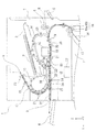
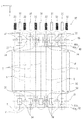
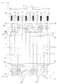
FIG. 1 is a schematic view showing a paper transport path in the printer according to the first embodiment. FIG. 2 is a schematic side view of the periphery of the recording unit. FIG. 3 is a schematic plan view of the periphery of the recording unit. FIG. 4 is a cross-sectional view of the ZX plane of the upstream transport portion according to the first embodiment. FIG. 5 is a cross-sectional view of the ZX plane of the wave shape forming portion according to the first embodiment. FIG. 6 is a diagram for explaining the positional relationship between the upstream transport portion and the wave shape forming portion in the height direction. FIG. 7 is a cross-sectional view of a ZX plane showing an example of the end shape of the support rib. FIG. 8 is a cross-sectional view of a ZX plane showing another example of the end shape of the support rib. FIG. 9 is a cross-sectional view of a ZX plane showing another example of the end shape of the support rib.
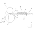
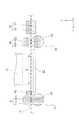
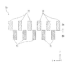
図10は、支持リブの他の一例を示す斜視図である。図11は、押さえ部の一例を示すZX平面の断面図である。図12は、押さえ部の他の一例を示す斜視図である。図13は、図12に示す押さえ部の側面図である。図14は、補助押さえ部について説明する概略側面図である。図15は、補助押さえ部について説明する概略平面図である。図16は、予備搬送ローラー対について説明する概略平面図である。図17は、予備波形状形成部について説明する概略平面図である。図18は、予備波形状形成部について説明するZX平面の断面図である。 FIG. 10 is a perspective view showing another example of the support rib. FIG. 11 is a cross-sectional view of a ZX plane showing an example of the holding portion. FIG. 12 is a perspective view showing another example of the pressing portion. FIG. 13 is a side view of the holding portion shown in FIG. FIG. 14 is a schematic side view for explaining the auxiliary pressing portion. FIG. 15 is a schematic plan view illustrating the auxiliary pressing portion. FIG. 16 is a schematic plan view illustrating a pair of preliminary transport rollers. FIG. 17 is a schematic plan view for explaining the preliminary wave shape forming portion. FIG. 18 is a cross-sectional view of a ZX plane for explaining the preliminary wave shape forming portion.
また、各図において示すX−Y−Z座標系はX軸方向が用紙の幅方向であり、装置奥行き方向を示し、Y軸方向が記録装置内の搬送経路における用紙の搬送方向(媒体搬送方向)であり、装置幅方向を示し、Z軸方向が装置高さ方向を示している。また、用紙が搬送されていく方向を下流といい、その反対を上流と言う。 Further, in the XYZ coordinate system shown in each figure, the X-axis direction is the width direction of the paper, the device depth direction is shown, and the Y-axis direction is the paper transport direction (medium transport direction) in the transport path in the recording device. ), And the Z-axis direction indicates the device height direction. In addition, the direction in which the paper is conveyed is called the downstream, and the opposite is called the upstream.
■■■プリンターの概要■■■
図1に示すプリンター1は、装置本体2の内部に設けられ、「媒体」の一例としての用紙に液体を吐出して記録を行う「記録部」の一例としてのラインヘッド10を備えている。本実施形態において、前記液体は水性インク等の水系インクである。
プリンター1は、用紙の第1面(おもて面とも言う)への記録後に、用紙を反転して第2面(裏面とも言う)への記録を行う両面記録が可能に構成されている。
■■■ Printer Overview ■■■
The
The
プリンター1の装置下部には、複数の用紙収容カセット7が設けられている。用紙収容カセット7に収容された用紙がラインヘッド10に向けて送られて、記録動作が行われる。ラインヘッド10による記録後の用紙は、ラインヘッド10の上方に設けられる第1媒体載置部3に用紙をスタックするための第1排出部8か、+Y軸方向側の側面に設けられる第2媒体載置部4に用紙をスタックするための第2排出部9かのいずれかに排出されるように構成されている。
A plurality of
■■■プリンターの搬送経路について■■■
次に、図1を参照して、プリンター1における用紙の搬送経路について説明する。以下において、第1面への記録後にそのまま用紙を排出する搬送経路について説明した後、両面記録を行う際の搬送経路について説明する。
■■■ About the transport route of the printer ■■■
Next, the paper transport path in the
用紙収容カセット7には複数枚の用紙が収容可能であり、最上位の用紙が媒体搬送方向下流側の給送経路14(図1において太い実線で示す)に搬送される。
給送経路14には、媒体搬送方向に沿って順に給送ローラー17と、複数枚の用紙を1枚に分離する分離ローラー対18が設けられている。
給送ローラー17は、図示しない駆動源により回転駆動する様に構成されている。また、分離ローラー対18はリタードローラーとも呼ばれ、後述するストレート経路12(図1において破線で示す)に向けて用紙を送る駆動ローラー18bと、駆動ローラー18bとの間で用紙をニップして分離する従動ローラー18aと、を備えて構成されている。
A plurality of sheets of paper can be stored in the
The
The feeding
用紙収容カセット7に収容された最上位の用紙は、給送ローラー17によりピックアップされて下流側に搬送される。この際、最上位の用紙とともに次位以降の用紙も搬送される場合があるが、分離ローラー対18により最上位の用紙と次位以降の用紙とが分離され、最上位の用紙のみが給送経路14に送られる。
The highest-level paper stored in the
分離ローラー対18の搬送方向下流側には、レジストローラー対19が設けられている。
本実施例ではレジストローラー対19の位置で、給送経路14とストレート経路12とが接続されている。
ストレート経路12は略直線状に延びる経路として構成され、レジストローラー対19の下流側に、上流側搬送部20、ラインヘッド10、及び下流側搬送部21が設けられている。ストレート経路12には、ラインヘッド10による記録領域K(図2)が含まれる。
A resist
In this embodiment, the feeding
The
上流側搬送部20は、ラインヘッド10の媒体搬送方向上流側に設けられる搬送部である。下流側搬送部21は、ラインヘッド10の媒体搬送方向下流側に設けられる搬送部である。
また、ラインヘッド10のヘッド面と対向する領域には、媒体支持部22が配置されている。媒体支持部22は用紙を記録面の反対側から支持する。
The upstream
Further, a
上流側搬送部20の媒体搬送方向上流側には、波形状形成部30が設けられている。波形状形成部30は、搬送される用紙P(図3を参照)に、媒体搬送方向に延在する山部T及び谷部Vが媒体搬送方向と交差する幅方向に沿って交互に位置する波形状を形成する構成部である。
前記波形状が形成された用紙Pは腰付けされて剛性が高まり、媒体支持部22上における用紙Pの姿勢が安定する。したがって、ラインヘッド10による記録において、良好な記録画質が得られる。
本発明の特徴を有する構成要素である上流側搬送部20、下流側搬送部21及び波形状形成部30の具体的な構成については、後で詳しく説明する。
A wave
The corrugated paper P is seated to increase its rigidity, and the posture of the paper P on the
The specific configurations of the
ラインヘッド10は、媒体支持部22上のラインヘッド10と対向する記録領域K(図2)に用紙が搬送された際、用紙の記録面にインク(液体)を噴射して記録を実行するように構成されている。ラインヘッド10は、インクを噴射するノズルが用紙の全幅をカバーする様に設けられた記録ヘッドであり、媒体幅方向への移動を伴わないで媒体幅全体に記録が可能な記録ヘッドとして構成されている。
尚、本実施例のプリンター1はラインヘッド10を備えているが、キャリッジに搭載されて媒体搬送方向と交差する方向に往復移動しながら媒体に液体を噴射して記録を行うシリアル型記録ヘッドを備えていてもよい。
When the paper is conveyed to the recording area K (FIG. 2) facing the
Although the
尚、プリンター1は、用紙収容カセット7に収容された用紙を給送して記録を行う場合の他、手差しトレイ5からの給紙が可能に構成されている。図1において点線Rは、手差しトレイ5から給紙した場合の搬送経路を示している。
手差しトレイ5から給紙された用紙は、搬送ローラー対6により送られてストレート経路12に合流し、用紙収容カセット7から給紙された用紙と同様に、ラインヘッド10による記録が行われる。
The
The paper fed from the bypass tray 5 is fed by the
続いて、ラインヘッド10による記録が行われた用紙は、記録後の用紙の排出先に応じて、ストレート経路12から、第1排出用経路13か第2排出用経路24かのいずれかへ送られる。
第1排出用経路13は、ラインヘッド10の下流側においてストレート経路12と接続され、用紙の記録面を下にして第1排出部8から排出されるように送る湾曲経路である。
第2排出用経路24は、ラインヘッド10の下流側においてストレート経路12からそのまま直線状に延びる経路であり、用紙の記録面を上にして第2排出部9から排出されるように送る経路である。
Subsequently, the paper recorded by the
The
The
ストレート経路12と第1排出用経路13及び第2排出用経路24との分岐位置S1には、記録後の用紙の搬送先を切り替える案内フラップ等の切替部26が設けられている。切替部26は、制御部27によってその動作が制御されている。尚、制御部27は、プリンター1における用紙の搬送動作(各種搬送ローラー対の駆動等)の他、切替部26の動作を含む記録に係わる動作を制御するものである。
At the branch position S1 between the
切替部26によって振り分けられて、ストレート経路12から第1排出用経路13に送られた用紙は、搬送ローラー対群23により搬送され、第1排出部8から排出され、記録面を下にして第1媒体載置部3に載置される。
また、ストレート経路12から第2排出用経路24に送られた用紙は、搬送ローラー対25によって搬送され、第2排出部9から排出されて、記録面を上にして第2媒体載置部4に載置される。
The paper sorted by the switching
Further, the paper sent from the
続いて、両面記録時の搬送経路について説明する。
プリンター1(図1)は、ラインヘッド10の下流側であって第1排出用経路13よりも上流側(本実施形態においては図1における搬送ローラー対群23の上流側)においてストレート経路12から分岐するスイッチバック経路15と、スイッチバック経路15に接続され、用紙の表裏(第1面と第2面)を反転させてストレート経路12に戻す反転経路16と、を備えている。尚、ストレート経路12とスイッチバック経路15の分岐位置S2、及びスイッチバック経路15と反転経路16の接続部には、それぞれ案内フラップ36、37が設けられており、これらの切り替えによって用紙が送られる経路が切り替えられるようになっている。尚、案内フラップ36、37の動作は制御部27によって制御される。
Subsequently, the transport path at the time of double-sided recording will be described.
The printer 1 (FIG. 1) is on the downstream side of the
プリンター1において両面記録を実行する場合、第1面への記録後の用紙はスイッチバック経路15に送られた後、反転経路16に送られる。反転経路16は、ストレート経路12の上流側に接続されており、反転経路16を通って反転された用紙は、第2面をラインヘッド10側にしてストレート経路12に送られる。そして、第2面への記録が実行される。
第2面への記録が行われた用紙は、切替部26によって振り分けられ、第1排出用経路13を経て第1排出部8から排出されるか、第2排出用経路24を経て第2排出部9から排出される。
When double-sided recording is executed in the
The paper on which the recording is performed on the second surface is sorted by the switching
■■■上流側搬送部について■■■
上流側搬送部20(図2〜図4)は、不図示の駆動源により駆動される上流側駆動ローラー40aと上流側従動ローラー40bを備え、用紙Pをニップして搬送する「搬送ローラー対」としての上流側搬送ローラー対40を備えて構成されている。
前述したように、上流側搬送部20の上流側には、波形状形成部30が設けられており、上流側搬送部20には、媒体搬送方向に延在する山部T及び谷部Vが媒体搬送方向と交差する幅方向に沿って交互に位置する波形状が形成された用紙Pがニップされる。
ここで、上流側搬送部20として、例えば幅方向に寸胴のローラー対を用いると、用紙Pをニップした際に波形状を均す或いは潰す等の、前記波形状を打ち消してしまう方向の作用を及ぼす虞がある。
■■■ About the upstream transport section ■■■
The upstream side transport unit 20 (FIGS. 2 to 4) includes an upstream
As described above, the wave
Here, when a roller pair having a barrel in the width direction is used as the
そこで、本実施形態の上流側搬送部20(図3、図4)は、山部T及び谷部Vのいずれか一方をニップするニップ部33と、山部T及び谷部Vのうち、ニップされていない他方を逃がす逃げ部34とが前記幅方向に沿って交互に配置されて構成されている。
具体的には、図3及び図4に示すように、複数のローラー対が媒体搬送方向と交差する幅方向(X軸方向)に間隔を空けて配置されて構成されている。
図4においては、上流側搬送ローラー対40のニップ部33は、用紙Pの波形状の山部Tをニップしており、用紙Pの谷部Vが逃げ部34に逃げることにより、前記波形状が潰されずに維持される様子が示されている。
Therefore, the upstream transport portion 20 (FIGS. 3 and 4) of the present embodiment has a
Specifically, as shown in FIGS. 3 and 4, a plurality of roller pairs are arranged at intervals in the width direction (X-axis direction) intersecting the medium transport direction.
In FIG. 4, the
この様に構成された上流側搬送部20により、以下の作用効果が得られる。
即ち、波形状形成部30によって形成された波形状を、上流側搬送部20が打ち消してしまう方向に作用することを抑制できる。つまり、波形状形成部30によって形成された波形状を良好に維持して用紙Pを搬送することができ、ひいてはより良好な記録品質を得ることができる。
The
That is, it is possible to prevent the
尚、上流側搬送部20は、本実施形態のように、個別のローラー対(上流側搬送ローラー対40)が間隔を空けて設け、前記間隔を逃げ部とする構成の他、例えば、前記幅方向に延設される一つのローラー対を、用紙をニップする部分(径が太い)と、用紙をニップしない部分(径が細い)とを有する構成として、前記用紙をニップしない細い部分を逃げ部とする構成とすることもできる。
The
■■■下流側搬送部について■■■
下流側搬送部21(図2、図3)は、前述した上流側搬送部20とほぼ同様の構成を有している。すなわち、不図示の駆動源により駆動される下流側駆動ローラー41aと下流側従動ローラー41bを備え、用紙Pをニップして搬送する「排出ローラー対」としての下流側搬送ローラー対41を備え、複数のローラー対が媒体搬送方向と交差する幅方向(X軸方向)に間隔を空けて配置されて構成されている(図3)。
言い換えると、下流側搬送部21(図3)は、用紙Pをニップする際、山部T及び谷部Vのいずれか一方をニップするニップ部38と、山部T及び谷部Vのうち、ニップ部38によってニップされていない他方を逃がす逃げ部39とが前記幅方向に沿って交互に配置されて構成されている。
■■■ About the downstream transport section ■■■
The downstream transport unit 21 (FIGS. 2 and 3) has substantially the same configuration as the
In other words, the downstream transport unit 21 (FIG. 3) has the
下流側搬送部21として、例えば幅方向に寸胴のローラー対を用いると、下流側搬送部21によりニップされた用紙Pの波形状は均され、その結果、上流側搬送部20と下流側搬送部21との間においても、用紙Pに形成された波形状が下流側に向けて元の形状に戻ろうとする。このことにより記録領域Kを搬送される用紙Pの波形状が変わり、用紙Pへの記録画質に影響を及ぼす場合がある。
When, for example, a roller pair having a barrel in the width direction is used as the
下流側搬送部21が、上流側搬送部20と同様に、ニップ部38と逃げ部39とが前記幅方向に沿って交互に配置されて成ることにより、上流側搬送部20と下流側搬送部21の間に位置する記録領域Kにおいて、より効果的に用紙Pの波形状を維持することができる。
Similar to the
また、上流側搬送部20(上流側搬送ローラー対40)におけるニップ部33と、下流側搬送部21(下流側搬送ローラー対41)におけるニップ部38は、図3に示すように、前記幅方向において対応する位置に配置されている。
このことによって、上流側搬送部20と下流側搬送部21との間の領域(特に、図2に示すラインヘッド10による記録領域K)において、一層効果的に用紙Pの波形状を維持することができる。
Further, as shown in FIG. 3, the
As a result, the wave shape of the paper P can be more effectively maintained in the region between the
■■■波形状形成部について■■■
以下、図2〜図6を参照して波形状形成部30について説明する。
波形状形成部30は、用紙Pに、媒体搬送方向(Y軸方向)に延在する山部T(図3において一点鎖線で示す)及び谷部V(図3において破線で示す)が媒体搬送方向と交差する幅方向(X軸方向)に沿って交互に位置する波形状を形成する構成部材である。
■■■ About the wave shape forming part ■■■
Hereinafter, the wave
In the corrugated
本実施形態において、波形状形成部30は、前述したように上流側搬送部20の上流側に設けられている(図2、図3)。
そして、図5に示すように、用紙Pにおいてラインヘッド10と対向する第1面側に接触する複数の「第1接触部」としての押さえ部32と、用紙Pにおいて前記第1面の反対面である第2面側に接触する「第2接触部」としての支持リブ31と、を備えている。押さえ部32と支持リブ31は、前記幅方向に間隔を空けて交互に配置されて構成されており(図3も参照)、押さえ部32と支持リブ31は、用紙Pに接触するそれぞれの端部側が、用紙Pの面に対する前記法線方向(本実施形態においては装置高さ方向Z)において一部が重なる様に設けられている。本実施形態においては、図5の上図に示すように、押さえ部32の端部(下部)と支持リブ31の端部(上部)が符号Dの部分で重なっている。
In the present embodiment, the wave
Then, as shown in FIG. 5, the
図5の下図のように、用紙Pが、押さえ部32と支持リブ31との間を搬送されると、支持リブ31に用紙Pが支持されつつ、押さえ部32によって符号Dの押し込み量で下方に押し込まれる。そして、用紙Pの支持リブ31によって支持された部分が山部Tとなり、押さえ部32によって押し込まれた部分が谷部Vとなり、用紙Pに波形状が形成される。
押さえ部32及び支持リブ31は、摩擦係数の低い材料(例えばPOM)で形成されていることが望ましい。用紙Pの波形状は、用紙Pが、押さえ部32と支持リブ31との間に入り込む際に、押さえ部32により用紙が押し込まれることにより形成される。このとき、用紙Pは前記幅方向に少しずつ移動する。押さえ部32と支持リブ31が、低摩擦部材で形成されていることにより、用紙Pに前記波形状を形成する際の抵抗を低減することができる。
As shown in the lower part of FIG. 5, when the paper P is conveyed between the
It is desirable that the
本実施形態において、支持リブ31は、前記幅方向(X軸方向)において、上流側搬送ローラー対40に対応する位置に設けられている。
このことにより、用紙Pに形成された波形状の山部Tが、上流側搬送ローラー対40のニップ部33にニップされる。
また、図6に示すように、用紙Pの面に対する法線方向(Z軸方向)におけるニップ部33の位置と、山部Tの頂部の位置とが揃う様に、支持リブ31が配設されている。
ニップ部33の高さ位置と、山部Tの頂部の位置とが揃っていることにより、前記波形状を有する用紙Pを上流側搬送部20としての上流側搬送ローラー対40にスムースにニップさせることができる。
In the present embodiment, the
As a result, the corrugated mountain portion T formed on the paper P is nipped into the
Further, as shown in FIG. 6, the
Since the height position of the
また、上流側搬送ローラー対40によるニップ部33と、波形状形成部30によって形成された山部Tの頂部の位置が、高さ方向においてずれていると、用紙Pが上流側搬送ローラー対40のニップ部33と波形状形成部30との間において、前記ずれた高さ方向に引っ張られ、前記波形状が打ち消される虞があるが、これを回避し、前記波形状が維持され易い構成とすることができる。
尚、ニップ部33の高さ位置と山部Tの頂部の位置は、完全に一致する必要はなく、例えば、ニップ部33から上流側搬送ローラー対40のローラー(例えば上流側従動ローラー40b)の半径以内程度の誤差であれば、適切に前記波形状を形成して維持しつつ用紙Pを搬送することができる。
Further, if the positions of the
The height position of the
また、波形状形成部30は、所定サイズ(例えば、A3、A4、B4、B5、リーガル、レター等の予め定められた規格サイズ)の用紙における前記幅方向の端部に、押さえ部32が配置されて構成されている(図3)。例えば、図3において、用紙PがA3(縦)サイズだとすると、この前記幅方向の両側の端部の位置に、押さえ部32がくるように配置されている(図5の下図も参照)。
このことにより、図5の下図に示すように、用紙Pの前記幅方向の端部が下を向く、すなわち、ラインヘッド10から離れる方向に向く波形状を形成することができる。以って、用紙Pの幅方向の端部がラインヘッド10に接触する虞を低減できる。
Further, in the wave
As a result, as shown in the lower figure of FIG. 5, it is possible to form a wave shape in which the end portion of the paper P in the width direction faces downward, that is, faces in a direction away from the
尚、波形状形成部30は、後述する実施例2の様に、媒体搬送方向において上流側搬送部20と略同じ位置に設けることもできるが、本実施形態のように上流側搬送部20の上流側に設けられることにより、波形状形成部30で波形状を形成した用紙Pを確実に上流側搬送部20に送り、上流側搬送部20が前記波形状を維持して搬送し易い構成とすることができる。
The wave
■■■支持リブについて■■■
以下において、波形状形成部30を構成する支持リブ31(第2接触部)について、更に詳しく説明する。
支持リブ31は、図7に示すように、端部の形状がZX断面で四角形状となる支持リブ31Aを用いることができる。
ここで、図7に示す支持リブ31Aの端部形状では、用紙Pに形成される波形状の山部Tは、支持リブ31の端部の角部35a、35aの間に盛り上がる様に形成され、支持リブ31の端部の高さ位置と、山部Tの頂部の高さ位置z1が一致しない場合がある。特に、用紙の剛性(コシの強さ弱さ)によって、山部Tの頂部の高さ位置z1が変わることが予想される。
そのため、上流側搬送ローラー対40によるニップ部33と、波形状形成部30によって形成された山部Tの頂部の高さ位置を合わせることが難しくなる場合がある。
■■■ Support ribs ■■■
Hereinafter, the support rib 31 (second contact portion) constituting the wave
As the
Here, in the end shape of the support rib 31A shown in FIG. 7, the wavy mountain portion T formed on the paper P is formed so as to bulge between the
Therefore, it may be difficult to align the height positions of the
このような場合には、支持リブ31として、図8に示すように端部形状のZX断面が、円または楕円の一部を切り取った円弧状に形成された支持リブ31Bを用いると良い。支持リブ31Bにより、用紙Pに形成される波形状の山部Tの頂部の高さ位置z1を、支持リブ31Bの端部の高さ位置に近づけることができる。また、用紙の剛性の違いによる山部Tの頂部の高さ位置z1の変化も少なくすることができる。
In such a case, as the
また、支持リブ31としては、図9に示すように、端部形状がZX断面で多角形状の支持リブ31Cを用いることもできる。支持リブ31Cは、角部35a、35aの内側に、角部35b、35bを有する多角形状をしている。このことにより、端部形状が、図8に示す支持リブ31Bの円弧状の端部形状に近づくので、図7に示す支持リブ31Aの場合よりも、用紙Pに形成される波形状の山部Tの頂部の高さ位置z1を、支持リブ31Cの端部の高さ位置に近づけることができる。
Further, as the
<<<支持リブの他の例について>>>
波形状形成部30を構成する「第2接触部」として、前述した支持リブ31(31A〜31C)に替えて、図10に示すような構成の支持リブ42を用いることができる。
支持リブ42は、媒体搬送方向に沿うY軸方向に回転軸43を備えるローラー部44を備えて構成されている。回転軸43は、軸受部45a、45bに取り付けられており、ローラー部44は両矢印Eの方向のいずれにも回転可能に構成されている。ローラー部44は、用紙Pの第2面に接触する。
前述したように、用紙Pに波形状を形成する際、用紙Pが、押さえ部32と支持リブ31との間に入り込んで、押さえ部32により用紙が押し込まれると、用紙Pが前記幅方向に少しずつ移動する。支持リブ42がローラー部44を備えることにより、用紙Pが前記幅方向に移動する際にローラー部44が回転し、用紙Pへの波形状の形成に伴う用紙Pの前記幅方向への移動の際の抵抗を低減することができる。
<<< About other examples of support ribs >>>
As the "second contact portion" constituting the wave
The
As described above, when forming a wavy shape on the paper P, when the paper P enters between the
■■■押さえ部について■■■
続いて、波形状形成部30を構成する押さえ部32(第1接触部)について、更に詳しく説明する。
波形状形成部30は、押さえ部32が、用紙Pを支持リブ31側に押し込む際の押し込み量(図5においてD)を変更可能に構成することができる。
押さえ部32の押し込み量を変更する構成としては、例えば、押さえ部32を支持リブ31に対して進退する方向に変位可能に設けるとともに、バネ等の付勢手段46(図11)を設け、押さえ部32の端部位置を変位させる構成とすることができる。尚、支持リブ31は固定されている。
■■■ About the holding part ■■■
Subsequently, the pressing portion 32 (first contact portion) constituting the wave
The corrugated
As a configuration for changing the pushing amount of the
波形状形成部30(図11)は、押さえ部32の押し込み量を、浅い押し込み量D1(図11の上図)から深い押し込み量D3(図11の中図)まで変更可能になっている。押さえ部32の押し込み量の変更は、制御部27が、不図示の駆動機構(例えばモーター及びラック&ピニオン機構で構成される)を制御することによって行われる。
波形状形成部30において、押さえ部32の押し込み量が変更可能であることにより、例えば、剛性、厚み等の違う用紙の種類に応じて前記波形状の山部Tの高さ、谷部Vの深さを変えることができる。
The wave shape forming portion 30 (FIG. 11) can change the pushing amount of the
Since the pushing amount of the
また、複数ある押さえ部32の押し込み量は、個別に変更可能に構成することもできる。その場合、押さえ部32の押し込み量を、図11の下図に示すように、前記幅方向(X軸方向)における端部側よりも中央部が多い構成とすることもできる。
図11の下図において、前記幅方向の両端部の押さえ部32の押し込み量はD1、その内側の押さえ部32の押し込み量はD2、中央部の二つの押さえ部32の押し込み量はD3となる様に設定されている。
Further, the pushing amount of the plurality of
In the lower figure of FIG. 11, the pushing amount of the
用紙Pの幅方向の全領域に亘って同じ押し込み量に設定された押さえ部32と支持リブ31との間で波形状をつける場合(例えば、図5の下図)、幅方向端部に比べて中央部のほうが、波形状の形成のために引き寄せる必要のある用紙幅が広くなるため、波形状の形成に必要な力が大きくなる。
複数ある押さえ部32の押し込み量を、前記幅方向(X軸方向)における端部側よりも中央部が多い構成(図11の下図)とすることにより、前記中央部における波形状の形成をより確実に行うことができる。
When a wavy shape is formed between the
By setting the pushing amount of the plurality of
尚、「波形状形成部」は、本実施例の波形状形成部30のように、「第1接触部(押さえ部32)」と「第2接触部(支持リブ31)」の双方をリブ状に形成する場合の他、「第1接触部」及び「第2接触部」の少なくとも一方を前記幅方向に間隔を空けて設けられるローラーにすることもできる。
The "wave shape forming portion" ribs both the "first contact portion (holding portion 32)" and the "second contact portion (support rib 31)" as in the wave
<<<押さえ部の他の例について>>>
波形状形成部30を構成する「第1接触部」としての押さえ部32に替えて、以下のような構成の押さえ部50(図12及び図13)を用いることができる。
押さえ部50は、用紙Pを支持リブ31側(図5の上図を参照)に押し込む際の押し込み量が、媒体搬送方向下流側に向かうに従って多くなる様に構成されている。
具体的には、押さえ部50は、用紙Pに接触する部分が媒体搬送方向上流側から下流側(+Y軸方向)に向かって下る斜面(符号51、56の部分)に形成されている。
尚、図12及び図13においては支持リブ31の記載が省略されているが、押さえ部50の下方(−Z軸方向)に支持リブ31が配置されている。また、前記幅方向に複数設けられた押さえ部50(図12)のうち、中央部の押さえ部を符号50a、押さえ部50aの両側の押さえ部を符号50b、前記幅方向の両端部の押さえ部を符号50cで示す。
<<< About other examples of the holding part >>>
Instead of the
The
Specifically, the
Although the description of the
更に押さえ部50は、媒体搬送方向上流側において用紙Pを支持リブ31側に押し込む第1領域53と、第1領域53に対し媒体搬送方向下流側において用紙Pを支持リブ31側に押し込む第2領域54と、を有している。第2領域54の媒体搬送方向下流側には、第3領域55が設けられている。
そして、前記幅方向に複数設けられた押さえ部50(50c、50b、50a、50b、50c)において、第1領域53における用紙Pの押し込み量は共通であり、第2領域54における用紙Pの押し込み量は、前記幅方向における端部側よりも中央部が多い構成である。
Further, the
Then, in the plurality of pressing portions 50 (50c, 50b, 50a, 50b, 50c) provided in the width direction, the pushing amount of the paper P in the
より具体的には、押さえ部50c、50b、50a、50b、50cにおいて、第1領域53は同じ角度、同じ長さの斜面56に形成されている。また、第2領域54は、中央部側の押さえ部50ほど、急な斜面51に形成されている(図13)。このことにより、第2領域54において、中央部の押さえ部50aの斜面51aの下流側の終点位置52aの位置では、前記幅方向の中央部の押さえ部50aによる押し込み量が最も多く、次に押さえ部50aの両側の押さえ部50b、50bによる押し込み量が多く、前記幅方向の端部側の押さえ部50c、50cによる押し込み量が最も少なくなっている。
また、第2領域54において、押さえ部50bの斜面51bの下流側の終点位置52bの位置では、中央部寄りの三つの押さえ部50b、50a、50bによる押し込み量が多く、前記幅方向の端部側の押さえ部50c、50cによる押し込み量が最も少なくなる。
尚、前記幅方向の端部側の押さえ部50c、50cの斜面51cの下流側の終点位置52c以降の領域である第3領域55においては、全ての押さえ部50が同じ押し込み量となる。
More specifically, in the
Further, in the
In the
押さえ部50による用紙Pの押し込み量が共通の第1領域53を有することにより、搬送される用紙Pを押さえ部50と支持リブ(図12、図13においては不図示)との間に誘うことができる。
また、押さえ部50による用紙Pの押し込み量が、前記幅方向における端部側よりも中央部が多い第2領域54を備えることにより、波形状の形成をスムース且つ容易に行うことができる。
By having the
Further, by providing the
■■■波形状形成部周辺の他の構成について■■■
<<<補助押さえ部について>>>
図14及び図15を参照して、補助押さえ部60について説明する。
下流側搬送部21としての下流側搬送ローラー対41の上流側には、補助押さえ部60が設けられている(図14及び図15)。補助押さえ部60は、前記幅方向において下流側搬送部21における逃げ部39に対応する位置に設けられている(図15)。補助押さえ部60は、波形状形成部30を構成する押さえ部32と同様の構成とすることができる。
下流側搬送部21における下流側搬送ローラー対41のニップ部38(山部Tがニップされる)の上流側において、補助押さえ部60が谷部Vを押さえることにより、用紙Pの波形状をしっかりと維持することができる。
補助押さえ部60が、Y軸方向において下流側搬送ローラー対41に十分近い場合、補助押さえ部60は、全ての逃げ部39に対応する位置に設けるのではなく、その一部の逃げ部39に対応する位置に設ける構成とすることもできる。
■■■ About other configurations around the wave shape forming part ■■■
<<< About the auxiliary presser >>
The auxiliary
An auxiliary pressing
On the upstream side of the nip portion 38 (where the mountain portion T is nipated) of the downstream side
When the auxiliary holding
<<<予備搬送ローラー対について>>>
図16を参照して、予備搬送ローラー対61について説明する。
波形状形成部30の上流側には、波形状形成部30に向けて用紙Pを送る予備搬送ローラー対61(図16)を設けることができる。予備搬送ローラー対61は、図1には記載されていないが、レジストローラー対19の下流側に設けられている。予備搬送ローラー対61は、用紙Pの前記幅方向の一部をニップするように構成されている。
本実施形態においては、予備搬送ローラー対61は、前記幅方向の中央部に一つ設けられている。
<<< Preliminary transport roller pair >>>
The preliminary
On the upstream side of the wave
In the present embodiment, one spare
例えば、波形状形成部30に向けて用紙Pを送るローラー対が、媒体を全幅に亘ってニップする構成である場合、波形状形成部30に到達した用紙Pの、前記幅方向における自由度が少なく、波形状が形成し難い。
本実施形態においては、予備搬送ローラー対61による用紙Pのニップは、前記幅方向の一部であるので、用紙Pが波形状形成部30に到達したときの用紙Pの前記幅方向における自由度を確保し、波形状形成部30による媒体への波形状の形成をより確実に行うことができる。
For example, when the roller pair that feeds the paper P toward the wavy
In the present embodiment, since the nip of the paper P by the preliminary
<<<予備波形状形成部について>>>
図17及び図18を参照して、予備波形状形成部70について説明する。
波形状形成部30(図17)の媒体搬送方向上流側には、波形状形成部30により用紙Pに形成される波形状よりも小さい山部T1と谷部V1を有する予備波形状を形成する予備波形状形成部70を設けることができる。
予備波形状形成部70は、図18に示すように、波形状形成部30と同様の構成を有し、用紙Pの第1面(ラインヘッド10と対向する面)と接触する予備押し込み部72と、用紙Pの第2面に接触する予備支持リブ71と、を備えている。予備押し込み部72による押し込み量は、波形状形成部30の押し込み量(例えば、図5の上図における押し込み量D)よりも小さいD0に設定されており(図18)、これにより、波形状形成部30により用紙Pに形成される波形状よりも山部T1と谷部V1を有する予備波形状(図17において符号74で示す範囲)が形成される。
波形状形成部30の上流側に、予備波形状形成部70が設けることにより、小さい予備波形状を付けた後に、波形状形成部30によってしっかりとした波形状を形成する構成とすることができる。以って、用紙Pに波形状を形成し易くすることができる。
<<< About the preliminary wave shape forming part >>>
The preliminary wave
On the upstream side of the wave shape forming portion 30 (FIG. 17) in the medium transport direction, a preliminary wave shape having a peak portion T1 and a valley portion V1 smaller than the wave shape formed on the paper P by the wave
As shown in FIG. 18, the preliminary wave
By providing the preliminary wave
[実施例2]
実施例2では図19及び図20に基づき、「波形状形成部」の他の例について説明する。図19は、実施例2に係る波形状形成部について説明する概略平面図である。図20は、実施例2に係る波形状形成部のZX平面の断面図である。
尚、本実施例において、実施例1と同一の構成については同一の符号を付し、その構成の説明は省略する。
[Example 2]
In the second embodiment, another example of the “wave shape forming portion” will be described with reference to FIGS. 19 and 20. FIG. 19 is a schematic plan view illustrating the wave shape forming portion according to the second embodiment. FIG. 20 is a cross-sectional view of the ZX plane of the wave shape forming portion according to the second embodiment.
In this embodiment, the same configurations as those in the first embodiment are designated by the same reference numerals, and the description of the configurations will be omitted.
実施例2に係る波形状形成部80は、媒体搬送方向において、上流側搬送部20(上流側搬送ローラー対40)と同じ位置に設けられている。
波形状形成部80は、用紙Pにおいてラインヘッド10(図19)と対向する第1面側に接触する「第1接触部」としての押さえ部82を備えている。
そして、本実施形態において、用紙Pにおいて前記第1面の反対面である第2面側に接触する「第2接触部」は、上流側搬送部20としての上流側搬送ローラー対40が兼ねている。
The wave
The wave
Then, in the present embodiment, the "second contact portion" that comes into contact with the second surface side, which is the opposite surface of the first surface of the paper P, also serves as the upstream side
押さえ部82は、複数の上流側搬送ローラー対40の間に設けられる、複数の逃げ部34の位置に配置されている。そして、押さえ部82の端部は、上流側搬送ローラー対40のニップ部33よりも下方に位置するように設けられている(図20の上図)。ニップ部33から押さえ部82の端部までが、波形状形成部80の押し込み量Dである。
以上のように構成された波形状形成部80により、用紙Pが上流側搬送ローラー対40によってニップされて搬送される際に、用紙Pに前記波形状を形成することができる。
本実施形態によれば、波形状形成部80を省スペースで配設し、装置の小型化を実現できる。
The
The corrugated
According to this embodiment, the wave
尚、本発明は上記実施例に限定されることなく、特許請求の範囲に記載した発明の範囲内で種々の変形が可能であり、それらも本発明の範囲内に含まれるものであることは言うまでもない。 It should be noted that the present invention is not limited to the above examples, and various modifications can be made within the scope of the invention described in the claims, and these are also included in the scope of the present invention. Needless to say.
1…インクジェットプリンター(記録装置)、2…装置本体、
3…第1媒体載置部、4…第2媒体載置部、5…手差しトレイ、
6…搬送ローラー対、7…用紙収容カセット、8…第1排出部、9…第2排出部、
10…ラインヘッド、12…ストレート経路、13…第1排出用経路、
14…給送経路、15…スイッチバック経路、16…反転経路、
17…給送ローラー、18…分離ローラー対、19…レジストローラー対、
20…上流側搬送部、21…下流側搬送部、22…媒体支持部、
23…搬送ローラー対群、24…第2排出用経路、25…搬送ローラー対、
26…切替部、27…制御部、28…搬送ローラー対、29…搬送ローラー対群、
30…波形状形成部、31…支持リブ(第2接触部)、
32…押さえ部(第1接触部)、33…ニップ部、34…逃げ部、
35a、35b…角部、36…案内フラップ、37…案内フラップ、
38…ニップ部、39…逃げ部、40…上流側搬送ローラー対、
40a…上流側駆動ローラー、40b…上流側従動ローラー、
41…下流側搬送ローラー対、41a…下流側駆動ローラー、
41b…下流側従動ローラー、42…支持リブ、43…回転軸、44…ローラー部、
45a、45b…軸受部、46…付勢手段、50…押さえ部、51…斜面、
53…第1領域、54…第2領域、55…第3領域、56…斜面、
60…補助押さえ部、61…予備搬送ローラー対、
70…予備波形状形成部、71…予備支持リブ、72…予備押し込み部、
80…波形状形成部、82…押さえ部、
P…用紙(媒体)、T…山部、V…谷部
1 ... Inkjet printer (recording device), 2 ... Device body,
3 ... 1st medium mounting part, 4 ... 2nd medium mounting part, 5 ... Manual feed tray,
6 ... Conveying roller pair, 7 ... Paper storage cassette, 8 ... 1st discharge section, 9 ... 2nd discharge section,
10 ... line head, 12 ... straight path, 13 ... first discharge path,
14 ... Feed route, 15 ... Switchback route, 16 ... Reverse route,
17 ... Feeding roller, 18 ... Separation roller pair, 19 ... Resist roller pair,
20 ... upstream transport section, 21 ... downstream transport section, 22 ... medium support section,
23 ... Conveying roller pair group, 24 ... Second discharge path, 25 ... Conveying roller pair,
26 ... Switching unit, 27 ... Control unit, 28 ... Conveying roller pair, 29 ... Conveying roller pair group,
30 ... Wave shape forming part, 31 ... Support rib (second contact part),
32 ... Pressing part (first contact part), 33 ... Nip part, 34 ... Escape part,
35a, 35b ... corners, 36 ... guide flaps, 37 ... guide flaps,
38 ... Nip part, 39 ... Relief part, 40 ... Upstream transport roller pair,
40a ... upstream drive roller, 40b ... upstream driven roller,
41 ... downstream side transport roller pair, 41a ... downstream side drive roller,
41b ... Downstream driven roller, 42 ... Support rib, 43 ... Rotating shaft, 44 ... Roller part,
45a, 45b ... bearing part, 46 ... urging means, 50 ... holding part, 51 ... slope,
53 ... 1st region, 54 ... 2nd region, 55 ... 3rd region, 56 ... slope,
60 ... Auxiliary retainer, 61 ... Preliminary transport roller pair,
70 ... Preliminary wave shape forming part, 71 ... Preliminary support rib, 72 ... Preliminary pushing part,
80 ... Wave shape forming part, 82 ... Holding part,
P ... Paper (medium), T ... Yamabe, V ... Tanibe
Claims (8)
前記記録部の媒体搬送方向上流側に設けられる上流側搬送部と、
前記記録部の媒体搬送方向下流側に設けられる下流側搬送部と、
前記上流側搬送部の媒体搬送方向上流側に設けられ、媒体搬送方向と交差する幅方向に交互に並んだ山部及び谷部から構成される波形状を前記媒体に形成する波形状形成部と、
を備え、
前記上流側搬送部は、前記幅方向に間隔を空けて並んだ複数のローラー対で構成され、
前記ローラー対は前記山部または前記谷部のいずれか一方をニップし、
前記波形状形成部は、
前記媒体において前記記録部と対向する第1面側に接触する複数の第1接触部と、
前記媒体において前記第1面の反対面である第2面側に接触する第2接触部と、が前記幅方向に間隔を空けて交互に配置されて構成され、
前記第1接触部と前記第2接触部は、前記媒体に接触するそれぞれの端部側が、前記媒体の面に対する法線方向において一部が重なり、
前記波形状形成部は、前記第1接触部が前記媒体を前記第2接触部側に押し込む際の押し込み量を変更可能に構成され、
前記第1接触部が前記媒体を前記第2接触部側に押し込む領域として、第1領域および前記第1領域に対して媒体搬送方向下流側の第2領域を有し、
前記幅方向に複数設けられた前記第1接触部において、前記第1領域における前記媒体の押し込み量は共通であり、
前記第2領域における前記媒体の押し込み量は、前記幅方向における端部側よりも中央部が多い構成である、
ことを特徴とする記録装置。 A recording unit that discharges liquid to the transported medium and records it.
An upstream transport unit provided on the upstream side of the recording unit in the medium transport direction,
A downstream transport unit provided on the downstream side of the recording unit in the medium transport direction,
A wave shape forming portion which is provided on the upstream side of the upstream side transporting portion in the medium transporting direction and is composed of peaks and valleys alternately arranged in the width direction intersecting the medium transporting direction in the medium. ,
With
The upstream transport unit is composed of a plurality of roller pairs arranged at intervals in the width direction.
The roller pair nips either the peak or the valley and
The wave shape forming portion is
A plurality of first contact portions in contact with the first surface side facing the recording portion in the medium,
In the medium, the second contact portions that come into contact with the second surface side, which is the opposite surface of the first surface, are alternately arranged at intervals in the width direction.
The first contact portion and the second contact portion are partially overlapped with each other on the end side in contact with the medium in the normal direction with respect to the surface of the medium.
The wavy shape forming portion is configured so that the pushing amount when the first contact portion pushes the medium toward the second contact portion can be changed.
The first contact portion has a first region and a second region on the downstream side in the medium transport direction with respect to the first region as a region for pushing the medium toward the second contact portion.
In the first contact portion provided in a plurality of width directions, the pushing amount of the medium in the first region is common.
The amount of the medium pushed in the second region is larger in the central portion than in the end side in the width direction.
A recording device characterized by that.
前記ローラー対は、前記山部をニップする、
ことを特徴とする記録装置。 In the recording device according to claim 1,
The roller pair nips the ridge.
A recording device characterized by that.
ことを特徴とする記録装置。 In the recording device according to claim 2, the nip position of the roller pair in the normal direction with respect to the surface of the medium and the position of the top of the mountain portion are aligned.
A recording device characterized by that.
前記波形状形成部は、所定サイズの媒体における前記幅方向の端部に前記第1接触部が配置されて構成されている、
ことを特徴とする記録装置。 In the recording device according to any one of claims 1 to 3.
The wavy shape forming portion is configured such that the first contact portion is arranged at an end portion in the width direction of a medium of a predetermined size.
A recording device characterized by that.
前記波形状形成部に向けて前記媒体を送る予備搬送ローラー対を備え、
前記予備搬送ローラー対は、前記媒体の前記幅方向の一部をニップする構成である、
ことを特徴とする記録装置。 In the recording device according to any one of claims 1 to 4.
A pair of preliminary transport rollers that feed the medium toward the wavy shape forming portion are provided.
The preliminary transport roller pair is configured to nip a part of the medium in the width direction.
A recording device characterized by that.
前記波形状形成部の媒体搬送方向上流側に設けられ、前記波形状形成部により前記媒体に形成される波形状よりも小さい山部と谷部を有する予備波形状を形成する予備波形状形成部を備える、
ことを特徴とする記録装置。 In the recording device according to any one of claims 1 to 4.
A preliminary wave shape forming portion provided on the upstream side of the wave shape forming portion in the medium transport direction and having peaks and valleys smaller than the wave shape formed on the medium by the wave shape forming portion. With,
A recording device characterized by that.
前記下流側搬送部は、前記幅方向に間隔を空けて並んだ複数の排出ローラー対であり、前記媒体をニップする際、前記山部及び前記谷部のいずれか一方をニップする、
ことを特徴とする記録装置。 In the recording device according to any one of claims 1 to 6.
The downstream transport unit is a plurality of discharge roller pairs arranged at intervals in the width direction, and when niping the medium, one of the peak portion and the valley portion is nipated.
A recording device characterized by that.
前記ローラー対におけるニップ位置と、前記排出ローラー対におけるニップ位置は、前記幅方向において対応している、
ことを特徴とする記録装置。 In the recording device according to claim 7,
The nip position in the roller pair and the nip position in the discharge roller pair correspond in the width direction.
A recording device characterized by that.
Priority Applications (4)
| Application Number | Priority Date | Filing Date | Title |
|---|---|---|---|
| JP2017108311A JP6919341B2 (en) | 2017-05-31 | 2017-05-31 | Recording device |
| CN201810494255.6A CN108973357B (en) | 2017-05-31 | 2018-05-17 | Recording apparatus |
| EP18173411.2A EP3409485B1 (en) | 2017-05-31 | 2018-05-21 | Recording apparatus |
| US15/991,187 US10350915B2 (en) | 2017-05-31 | 2018-05-29 | Recording apparatus |
Applications Claiming Priority (1)
| Application Number | Priority Date | Filing Date | Title |
|---|---|---|---|
| JP2017108311A JP6919341B2 (en) | 2017-05-31 | 2017-05-31 | Recording device |
Publications (3)
| Publication Number | Publication Date |
|---|---|
| JP2018202670A JP2018202670A (en) | 2018-12-27 |
| JP2018202670A5 JP2018202670A5 (en) | 2020-06-25 |
| JP6919341B2 true JP6919341B2 (en) | 2021-08-18 |
Family
ID=62222427
Family Applications (1)
| Application Number | Title | Priority Date | Filing Date |
|---|---|---|---|
| JP2017108311A Active JP6919341B2 (en) | 2017-05-31 | 2017-05-31 | Recording device |
Country Status (4)
| Country | Link |
|---|---|
| US (1) | US10350915B2 (en) |
| EP (1) | EP3409485B1 (en) |
| JP (1) | JP6919341B2 (en) |
| CN (1) | CN108973357B (en) |
Families Citing this family (3)
| Publication number | Priority date | Publication date | Assignee | Title |
|---|---|---|---|---|
| US10647133B2 (en) * | 2017-10-31 | 2020-05-12 | Seiko Epson Corporation | Medium transporting device and recording apparatus |
| US11433693B2 (en) * | 2019-12-27 | 2022-09-06 | Seiko Epson Corporation | Recording apparatus |
| JP2022048548A (en) * | 2020-09-15 | 2022-03-28 | セイコーエプソン株式会社 | Recording device, and control method for recording device |
Family Cites Families (18)
| Publication number | Priority date | Publication date | Assignee | Title |
|---|---|---|---|---|
| JPS60148760U (en) * | 1984-03-13 | 1985-10-02 | 富士ゼロックス株式会社 | paper conveyance device |
| JPH0312846U (en) * | 1989-06-21 | 1991-02-08 | ||
| JP3432052B2 (en) * | 1994-09-02 | 2003-07-28 | キヤノン株式会社 | Ink jet recording device |
| JP2000071532A (en) * | 1998-08-27 | 2000-03-07 | Canon Inc | Ink-jet recording apparatus |
| JP4194205B2 (en) * | 1999-05-14 | 2008-12-10 | キヤノン株式会社 | Inkjet recording device |
| JP2001341886A (en) * | 2000-06-01 | 2001-12-11 | Canon Inc | Recording device |
| JP2005047227A (en) * | 2003-07-31 | 2005-02-24 | Canon Inc | Double-sided recording device |
| JP4730557B2 (en) * | 2006-02-27 | 2011-07-20 | セイコーエプソン株式会社 | Recording medium feeding apparatus, recording apparatus, and liquid ejecting apparatus |
| JP4858193B2 (en) * | 2007-01-30 | 2012-01-18 | ブラザー工業株式会社 | Inkjet recording platen and inkjet recording apparatus |
| US20090109250A1 (en) * | 2007-10-26 | 2009-04-30 | Johnston Benjamin M | Method and apparatus for supporting a substrate |
| JP5322490B2 (en) * | 2008-05-02 | 2013-10-23 | キヤノン株式会社 | Sheet discharging apparatus and image forming apparatus |
| JP5435214B2 (en) * | 2009-05-29 | 2014-03-05 | セイコーエプソン株式会社 | Medium feeding device and recording device |
| JP2013059998A (en) * | 2011-08-23 | 2013-04-04 | Ricoh Co Ltd | Image forming apparatus |
| JP5760989B2 (en) * | 2011-11-28 | 2015-08-12 | ブラザー工業株式会社 | Inkjet recording device |
| US8967793B2 (en) * | 2012-03-15 | 2015-03-03 | Ricoh Company, Ltd. | Sheet transport device and image forming device |
| US8882215B2 (en) * | 2012-03-30 | 2014-11-11 | Brother Kogyo Kabushiki Kaisha | Method and inkjet printer for acquiring gap information |
| JP6186992B2 (en) | 2013-07-29 | 2017-08-30 | ブラザー工業株式会社 | Inkjet recording device |
| JP5815152B1 (en) * | 2015-07-01 | 2015-11-17 | 株式会社新興製作所 | Page turning device |
-
2017
- 2017-05-31 JP JP2017108311A patent/JP6919341B2/en active Active
-
2018
- 2018-05-17 CN CN201810494255.6A patent/CN108973357B/en active Active
- 2018-05-21 EP EP18173411.2A patent/EP3409485B1/en active Active
- 2018-05-29 US US15/991,187 patent/US10350915B2/en active Active
Also Published As
| Publication number | Publication date |
|---|---|
| US20180345688A1 (en) | 2018-12-06 |
| US10350915B2 (en) | 2019-07-16 |
| EP3409485B1 (en) | 2020-12-30 |
| EP3409485A1 (en) | 2018-12-05 |
| CN108973357A (en) | 2018-12-11 |
| JP2018202670A (en) | 2018-12-27 |
| CN108973357B (en) | 2020-02-21 |
Similar Documents
| Publication | Publication Date | Title |
|---|---|---|
| JP5197162B2 (en) | Sheet conveying apparatus and image forming apparatus | |
| JP4999537B2 (en) | Recording device | |
| JP5605140B2 (en) | Image forming apparatus | |
| JP6919341B2 (en) | Recording device | |
| JP6217898B2 (en) | Recording device | |
| US8162314B2 (en) | Image printing apparatus | |
| US11413886B2 (en) | Medium transporting apparatus, medium processing apparatus, and recording system | |
| JP7119852B2 (en) | Media ejection device, media processing device, and recording system | |
| US9694606B2 (en) | Ink-jet recording apparatus | |
| JP7243454B2 (en) | Media ejection device, media processing device, and recording system | |
| JP7223270B2 (en) | Media transport device, recording device | |
| JP4692763B2 (en) | RECORDED MEDIUM SUPPORT DEVICE, RECORDING DEVICE, LIQUID EJECTING DEVICE | |
| JP7131262B2 (en) | MEDIA TRANSPORT DEVICE, MEDIA HANDLING DEVICE AND RECORDING SYSTEM | |
| JP6525135B2 (en) | Recording device | |
| US9168769B2 (en) | Recording apparatus | |
| JP2008273675A (en) | Recording device | |
| JP5136753B2 (en) | Recording material support device, recording device | |
| CN108973356B (en) | Recording apparatus | |
| US10099487B2 (en) | Image recording apparatus | |
| JP6953951B2 (en) | Recording device | |
| US9815306B2 (en) | Ink-jet recording apparatus | |
| US20140063110A1 (en) | Recording device | |
| JP6503870B2 (en) | Sheet feeding apparatus and inkjet recording apparatus | |
| JP6232896B2 (en) | Medium conveying apparatus and recording apparatus | |
| JP2010158844A (en) | Printer |
Legal Events
| Date | Code | Title | Description |
|---|---|---|---|
| A521 | Request for written amendment filed |
Free format text: JAPANESE INTERMEDIATE CODE: A523 Effective date: 20200424 |
|
| A621 | Written request for application examination |
Free format text: JAPANESE INTERMEDIATE CODE: A621 Effective date: 20200424 |
|
| A977 | Report on retrieval |
Free format text: JAPANESE INTERMEDIATE CODE: A971007 Effective date: 20210326 |
|
| A131 | Notification of reasons for refusal |
Free format text: JAPANESE INTERMEDIATE CODE: A131 Effective date: 20210407 |
|
| A521 | Request for written amendment filed |
Free format text: JAPANESE INTERMEDIATE CODE: A523 Effective date: 20210430 |
|
| TRDD | Decision of grant or rejection written | ||
| A01 | Written decision to grant a patent or to grant a registration (utility model) |
Free format text: JAPANESE INTERMEDIATE CODE: A01 Effective date: 20210622 |
|
| A61 | First payment of annual fees (during grant procedure) |
Free format text: JAPANESE INTERMEDIATE CODE: A61 Effective date: 20210705 |
|
| R150 | Certificate of patent or registration of utility model |
Ref document number: 6919341 Country of ref document: JP Free format text: JAPANESE INTERMEDIATE CODE: R150 |