JP4191533B2 - Sample analysis apparatus and method - Google Patents
Sample analysis apparatus and method Download PDFInfo
- Publication number
- JP4191533B2 JP4191533B2 JP2003145036A JP2003145036A JP4191533B2 JP 4191533 B2 JP4191533 B2 JP 4191533B2 JP 2003145036 A JP2003145036 A JP 2003145036A JP 2003145036 A JP2003145036 A JP 2003145036A JP 4191533 B2 JP4191533 B2 JP 4191533B2
- Authority
- JP
- Japan
- Prior art keywords
- sample
- rack
- marking
- control unit
- container
- Prior art date
- Legal status (The legal status is an assumption and is not a legal conclusion. Google has not performed a legal analysis and makes no representation as to the accuracy of the status listed.)
- Expired - Fee Related
Links
Images


Classifications
-
- G—PHYSICS
- G01—MEASURING; TESTING
- G01N—INVESTIGATING OR ANALYSING MATERIALS BY DETERMINING THEIR CHEMICAL OR PHYSICAL PROPERTIES
- G01N35/00—Automatic analysis not limited to methods or materials provided for in any single one of groups G01N1/00 - G01N33/00; Handling materials therefor
- G01N35/00584—Control arrangements for automatic analysers
- G01N35/00594—Quality control, including calibration or testing of components of the analyser
- G01N35/00603—Reinspection of samples
-
- G—PHYSICS
- G01—MEASURING; TESTING
- G01N—INVESTIGATING OR ANALYSING MATERIALS BY DETERMINING THEIR CHEMICAL OR PHYSICAL PROPERTIES
- G01N35/00—Automatic analysis not limited to methods or materials provided for in any single one of groups G01N1/00 - G01N33/00; Handling materials therefor
- G01N35/00584—Control arrangements for automatic analysers
- G01N35/00722—Communications; Identification
- G01N35/00732—Identification of carriers, materials or components in automatic analysers
- G01N2035/00742—Type of codes
- G01N2035/00772—Type of codes mechanical or optical code other than bar code
Landscapes
- Engineering & Computer Science (AREA)
- Quality & Reliability (AREA)
- Physics & Mathematics (AREA)
- Health & Medical Sciences (AREA)
- Life Sciences & Earth Sciences (AREA)
- Chemical & Material Sciences (AREA)
- Analytical Chemistry (AREA)
- Biochemistry (AREA)
- General Health & Medical Sciences (AREA)
- General Physics & Mathematics (AREA)
- Immunology (AREA)
- Pathology (AREA)
- Automatic Analysis And Handling Materials Therefor (AREA)
Description
【0001】
【発明の属する技術分野】
この発明は、試料分析装置および方法に関し、例えば、血液分析装置、生化学分析装置、尿分析装置や工業用粒子分析装置などに関する。
【0002】
【従来の技術】
この発明に関連する技術として次のようなものが知られている。
(1)ラック移送コンベアおよびラック移送コンベアの下流端に接続されたラック分類コンベアからなる移送路と、ラック移送コンベアの片側に設けられたラック供給コンベアと、ラック供給コンベアの近傍に設けられた第1試料バーコードリーダと、ラック移送コンベアの下流端近傍に設けられホストコンピュータからの指令により作動するプリンタと、ラック供給コンベアとプリンタとの間の移送路に沿って設けられたラックバーコードリーダおよび第2試料バーコードリーダと、ラック分類コンベアの片側に設けられ所定数の区画された収納部を有するテーブルと、ラック分類コンベアに沿って設置され各収納部と関連する複数の押し出し機構とを備える試料分類装置(例えば、特許文献1参照)。
【0003】
(2)試料容器ラックを移送する移送ユニットと、移送ユニットによって移送される試料分析容器ラックから試料容器識別信号を読み出すための試料容器IDリーダと、試料容器を収納するための試料容器収納ラックを搭載可能な試料容器収容ラックテーブルと、試料容器ラックから試料容器を取り出して試料容器収納ラックへ収容するための試料容器移送手段と、試料容器を試料容器収容ラックへ収容する順序を制御するための制御ユニットとを備える試料容器移送装置(例えば、特許文献2参照)。
【0004】
【特許文献1】
米国特許第5,150,795号
【特許文献2】
米国特許第6,255,614号
【0005】
【発明が解決しようとする課題】
従来の血液分析装置のような試料分析装置は、試料の分析を行う本体と、ラックを移送するコンベアとから構成されている。ラックには、試料を収容した試料容器が一列に配列されている。試料容器には、試料を特定するための識別番号(ID)を表すバーコードが貼り付けられている。コンベアは、ラック移送機構とストック部(ラック回収部)などを備える。ラック移送機構は、ラックを搭載し、そのラックをストック部(ラック回収部)へ移送する。本体は、バーコードリーダと、吸引部と、分析部などを備える。本体は、ラック移送機構によって移送される試料容器のIDを読み取り、試料容器内から試料を吸引し、吸引した試料の分析を行う。
【0006】
分析される試料には、分析結果が異常であるため再検査が必要なもの、内部に収容している試料が感染性のウイルスに感染しているため取扱に特に注意が必要なものなど様々なものがある。従って、試料分析装置の使用者は分析が終了した試料がどのようなものであるかの識別をする必要がある。
【0007】
しかし、上記の従来の試料分析装置では、使用者が、分析が終了した試料がどのようなものであるかを識別をするためには、ラック回収部に回収された試料容器からIDを読み取ること、および、IDと分析結果やウイルス感染の有無とを照合させることが必要であった。この作業は非常に煩雑なものである。
この発明はこのような事情を考慮してなされたもので、マーキング機構を備え特定の試料容器にマークをつける試料分析装置を提供することによって上記の課題を解決するものである。
【0008】
【課題を解決するための手段】
この発明は、試料を収容した容器に試料分析装置の使用者に視認可能な目印を付加するマーカーとして互いに色の異なる複数のマーカーを備えるマーキング機構と、試料からの信号を検出する検出機構と、検出機構によって検出された信号を分析して得られる分析結果に基づいて試料の再検査が必要か否かを決定し、試料の再検査が必要であればその試料を収容した容器に、分析結果の分析項目に応じて所定の色の目印を付加するようにマーキング機構の動作を制御する制御部とを備える試料分析装置を提供するものである。この構成によれば、試料の情報に対応して容器に目印が付加されるので、使用者は所望の容器を容易に識別することができる。
【0009】
【発明の実施の形態】
以下、図面に示す実施形態に基づいてこの発明を詳述する。これによってこの発明が限定されるものではない。なお、試料分析装置の実施形態として血液分析装置を用いて説明する。
第1実施形態
図1はこの発明の第1実施形態に係る血液分析装置の斜視図である。血液分析装置100は、本体218と、コンベア104から構成される。本体218はタッチパネル式ディスプレイ102などを備える。コンベア104は攪拌吸引機構111およびマーキング機構215などを備える。
【0010】
本体218は、血液中の血球の数や分布を算出する機能を有しており、そのハードウエア構成には、例えば、SF−3000(シスメックス(株)製)の本体を利用することができる。
マーキング機構215を除くコンベア104のハードウエア構成には、例えば、SF−3000(シスメックス(株)製)のコンベアを利用することができる。
図2は血液分析装置100の構成を説明する説明図である。
【0011】
まず、コンベア104について説明する。
コンベア104は、ラック移送機構222とラック横送り機構210とラック回収機構216と攪拌吸引機構111とマーキング機構215とを備える。
ラック移送機構222は、試料容器200を搭載した複数台のラック226を搭載し矢印Aの方向へ移送する。ラック移送機構222には、ラック226の移送を開始させるためのスタートスイッチ204が設けられている。
【0012】
ラック226は、図3に示すように、10本の試料容器200が搭載できるように試験管立て状の形状をしている。ラック226は、試料容器200に貼り付けられたバーコード8を読み取り可能とするためのスリット9が縦方向に設けられている。試料容器200は、有底円筒形の試験管状容器で上端開口はゴム製のキャップ7で塞がれ、内部に試料として血液を収容している。バーコード8は、試料容器200の内部に収容されている血液を特定するためのIDを表すものである。なお、バーコード8には、IDに加えて、血液を採取された患者を特定する情報や採血条件を表す情報などを表してもよい。バーコード8に代えて、ICチップを用いてもよい。Pは隣り合う試料容器間の距離を示しており、この距離を1ピッチとする。
【0013】
図2に戻り、コンベア104について説明する。
ラック横送り機構210は、ラック移送機構222によって移送されたラック226を矢印Bの方向に移送(横送り)する。ラック横送り機構210は、ラック226を1ピッチずつ横送りする。従って、ラック横送り機構210がラック226を横送りした回数によって検査対象となる試料容器200がラック横送り機構210のどの位置にあるかを判断することができる。
【0014】
Rはバーコード読み取り位置を示している。バーコード読み取り位置Rは本体218に固定されたバーコードリーダ217に対向する位置である。バーコード読み取り位置Rに試料容器200があればバーコードリーダ217は試料容器200に貼り付けられたバーコード8(図3参照)をスリット9(図3参照)を介して読み取ることができる。
Kは容器取出し位置を示している。容器取出し位置Kは横送り機構210に固定された攪拌吸引機構111に対向する位置である。容器取出し位置Kに試料容器200があれば攪拌吸引機構111はラック226から試料容器200を取出すことができる。
【0015】
Mはマーキング位置を示している。この位置は横送り機構210に固定されたマーキング機構215に対向する位置である。マーキング位置Mに試料容器200があればマーキング機構215は試料容器200にマーキングする(目印を付ける)ことができる。
なお、バーコード読み取り位置Rと容器取出し位置Kとの距離は1ピッチであり、バーコード読み取り位置Rとマーキング位置Mとの距離は5ピッチである。
ラック回収機構216は、ラック横送り機構210によって横送りされたラック226を矢印Cの方向に移送して回収する。
【0016】
攪拌吸引機構111は、ラック移送機構222とラック回収機構216の間に位置している。攪拌吸引機構111は、ラック横送り機構210によって横送りされるラック226から容器取出し位置Kに配置された試料容器200を取出し、攪拌し、その内の試料を所定量だけ吸引し、その後、試料容器200をラック226内の元の場所に戻す。なお、攪拌吸引機構111は、横送り機構210に隣接して本体218に固定されてもよい。
【0017】
マーキング機構215は横送り機構210に固定されている。マーキング機構215は、バーコードリーダ217によるバーコードの読み取りおよび攪拌吸引機構111による試料の吸引が終了した試料容器200にマークを付けることができる位置に固定されている。なお、マーキング機構215は、横送り機構210に隣接して本体218に固定されてもよい。マーキング機構215の構成については後述する。
【0018】
次に、本体218について説明する。
本体218は、タッチパネル式ディスプレイ102と制御部201と試料調製機構213と検出機構214とバーコードリーダ217とを備えている。
試料調製機構213は攪拌吸引機構111とチューブ120aで接続されており、吸引された試料に定量、希釈、溶血などの処理をして検出機構214にチューブ120bを介して移送する。試料調製機構213としては、例えば、米国特許5,524,496号に記載されているサンプリングバルブを利用することができる。なお、チューブ120aは横送り機構210の内部に配置されており、ラック226の動作を妨げるものではない。
検出機構214は試料調製機構213から移送された試料に光を照射して得られる光学信号および試料調製機構213から移送された試料に電流を流して得られる電気信号をデジタル化して制御部201に送信する。検出機構214としては、例えば、米国特許第5,737,078号に記載されているフローサイトメータや米国特許公開2002−0034824号公報に記載された電気抵抗式検出部を利用することができる。
【0019】
タッチパネル式ディスプレイ102は、入力部202と出力部203を兼ねる。
入力部202は、ユーザによる情報の入力を受け付け、制御部201に送信する。
出力部203は、制御部201から送信される情報を表示する。
バーコードリーダ217は、試料容器200に貼付されているバーコード8(図3参照)から識別情報(ID)を読み取り、読み取ったIDを制御部201に送信する。なお、バーコード8に代えてICチップを用いる場合、バーコードリーダ217に代えてICチップリーダを用いる。
【0020】
制御部201は、CPU,ROM,RAM,HDD等からなるマイクロコンピュータで構成される。制御部201からマーキング機構215に向かう矢印に付けられている記号Sは、制御部201からマーキング機構215に向けて出力される信号を示している。
【0021】
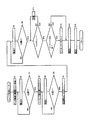
次に、図4を使用して制御部201の内部構成を説明する。
制御部201は、分析部130、再検査決定部132、コンベア制御部136、バーコードリーダ制御部137、攪拌吸引機構制御部138、試料調製機構制御部140、検出機構制御部142、マーキング機構制御部144、正常値テーブル146および再検査テーブル148を備えている。コンベア制御部136は、位置判断部134およびマーキング判断部135を備えている。制御部201には、ラック移送機構222、ラック横送り機構210、ラック回収機構216、攪拌吸引機構111、入力部202、出力部203、試料調製機構213、検出機構214、マーキング機構215およびバーコードリーダ217が接続されている。
【0022】
分析部130は、検出機構214から送信される光学信号および電気信号から分析結果(白血球数、赤血球数、血小板数、ヘモグロビン濃度など)を算出するとともに、算出された分析結果をバーコードリーダ217で読み取られたIDと対応づけて一時的に記憶する。
再検査決定部132は、分析部130に一時的に記憶されている分析結果から試料の再検査の必要性の有無を正常値テーブル146を使用して決定し、その結果をIDとともに再検査テーブル148に記憶させる。
【0023】
図5は、正常値テーブル146の内容を説明する説明図である。正常値テーブル146には、白血球数、赤血球数、血小板数およびヘモグロビン濃度について、正常値範囲(下限値と上限値)が対応付けて記憶されている。再検査決定部132(図4)は、分析結果のうち、白血球数、赤血球数、血小板数およびヘモグロビン濃度が全て正常範囲内にある場合には、再検査が不要と決定し、1つでも正常範囲外にある場合には、再検査が必要と決定する。なお、正常値テーブル146には、最適値や平均値を正常値範囲として記憶しておいて、再検査決定部132は分析結果とそれらの値との差が所定値以上の場合に再検査が必要と決定してもよい。
【0024】
図6は、再検査テーブル148の内容を説明する説明図である。再検査テーブル148には、再検査決定部132によって決定された再検査の必要性の有無がIDと対応付けられて記憶される。この例は、IDが0001、0004および0011の試料の再検査が必要であることを示している。
【0025】
図4に戻り、制御部201の内部構成の説明を続ける。
コンベア制御部136は、ラック移送機構222、ラック横送り機構210およびラック回収機構216の動作を制御する。
位置判断部134は、検査対象となる試料容器200がラック横送り機構210のどの位置にあるかを判断する。試料容器200の位置はラック横送り機構210を動作させた回数から判断される。コンベア制御部136がラック横送り機構210に1回動作指令を出すと、ラック横送り機構210は、ラック226を1ピッチだけ横送りする。前述したように、バーコード読み取り位置Rとマーキング位置Mとの距離は5ピッチである(図2参照)。従って、位置判断部134は、バーコードリーダ217によるバーコードの読み取りの後、コンベア制御部136がラック横送り機構210に5回動作指令を出した後には、バーコードを読み取られた試料容器200はマーキング位置Mにあると判断することができる。なお、位置判断部134は、ラック横送り機構210にセンサを設けておいて、そのセンサからの信号に基づいて試料容器200の位置を判断するように構成してもよい。
【0026】
マーキング判断部135は、再検査テーブル148を使用してマーキングが必要かどうかを判断する。具体的には、再検査が必要と決定された試料にはマーキングが必要と判断し、再検査が不要と決定された試料にはマーキングが不要と判断する。この例では、IDが0001、0004および0011の試料の再検査が必要である(図6参照)ため、これらの試料にはマーキングが必要であると判断し、それ以外の試料にはマーキングが不要であると判断する。
【0027】
バーコードリーダ制御部137は、バーコードリーダ217の動作を制御する。攪拌吸引機構制御部138は、攪拌吸引機構111の動作を制御する。試料調製機構制御部140は、試料調製機構213の動作を制御する。検出機構制御部142は検出機構214の動作を制御する。マーキング機構制御部144は、マーキング機構215の動作を制御する。
なお、制御部201とタッチパネル式ディスプレイ102には、パーソナルコンピュータを用いてもよい。
【0028】
制御部201は、分析部130、再検査決定部132、正常値テーブル146および再検査テーブル148を備える第1制御部としてパーソナルコンピュータを用い、コンベア制御部136、バーコードリーダ制御部137、攪拌吸引機構制御部138、試料調製機構制御部140、検出機構制御部142およびマーキング機構制御部144を備える第2制御部としてマイクロコンピュータを用い、両者を接続することによって構成してもよい。
【0029】
次に、図7を使用してマーキング機構215を説明する。図7はマーキング機構215の構成を説明する説明図である。同図に示すように、横送り機構210に固定されたフレーム1に電動式リニアアクチュエータ2が設置され、リニアアクチュエータ2の駆動ロット3とマーキングペン4とがアーム5を介して結合されている。マーキングペン4としては、例えば、メトロンマーカー(朝日物産株式会社販売)が使用できる。なお、マーキングペン4に代えて、スタンプやノズルからインクを噴射させる機構やシールを貼り付ける機構などのマーカーが使用できる。
【0030】
駆動制御部6は、リニアアクチュエータ2のドライバー回路を備え、マーキング機構制御部144(図4参照)からの出力信号Sを受けてリニアアクチュエータ2を駆動させる。リニアアクチュエータ2の駆動によりマーキングペン4は垂直方向(矢印D方向および矢印E方向)に移動する。
リニアアクチュエータ2は、マーキングペン4が下降したときにその先端が試料容器200の上部に結合されているキャップ7に接触してインクをキャップ7の上面に塗布(マーキング)する位置までマーキングペン4を下降させる。その後、マーキングペン4は初期位置へ復帰する。なお、この明細書においては、キャップ7は試料容器200の一部であると定義する。
図2、図4、図8、図9などを参照して、血液分析装置100の動作について説明する。
【0031】
図8は、制御部201における処理手順を概略的かつ総括的に示すフローチャートである。
ステップS101では、コンベア制御部136がラック226の移送動作を制御する処理が実行される。
ステップS102では、バーコードリーダ制御部137がバーコード読み取り動作を制御する処理が実行される。
ステップS103では、攪拌吸引機構制御部138が攪拌吸引動作を制御する処理が実行される。
ステップS104では、試料調製機構制御部140が試料調製動作を制御する処理が実行される。
ステップS105では、検出機構制御部142が検出動作を制御する処理が実行される。
ステップS106では、分析部130が分析を制御する処理が実行される。
ステップS107では、再検査決定部132が再検査の必要性の有無の決定を制御する処理が実行される。
ステップS108では、マーキング機構制御部144がマーキング動作を制御する処理が実行される。
ステップS101からステップS108の処理は順次繰り返される。
【0032】
図9は、ステップS101で実行される処理の詳細を示すフローチャートである。
ステップS1では、ラック226をラック移送機構222からラック横送り機構210へ移送させる処理が実行される。
ステップS2では、ラック横送り機構210上のラック226を1ピッチ横送りさせる処理が実行される。
ステップS3では、検査対象となる試料容器200がバーコード読み取り位置Rにあるかを判断する処理が位置判断部135によって実行される。試料容器200がバーコード読み取り位置Rにあれば、バーコード読み取りフラグを“1”にする処理が実行される(ステップS4)。試料容器200がバーコード読み取り位置Rになければ、ステップS2の処理が再度実行される。なお、ステップS102(図8参照)では、バーコード読み取りフラグが“1”であればバーコードリーダ217にバーコードの読み取り動作をさせる処理が実行される。
【0033】
ステップS5では、バーコードリーダ217によるバーコードの読み取り動作が終了した後に、ラック横送り機構210上のラック226を1ピッチ横送りさせる処理が実行される。
ステップS6では、検査対象となる試料容器200が容器取出し位置Kにあるかを判断する処理が位置判断部135によって実行される。試料容器200が容器取出し位置Kにあれば、容器取出しフラグを“1”にする処理が実行される(ステップS7)。試料容器200が容器取出し位置Kになければ、ステップS5の処理が再度実行される。なお、ステップS103(図8参照)では、容器取出しフラグが“1”であれば攪拌吸引機構111に攪拌吸引動作をさせる処理が実行される。この処理によって、攪拌吸引機構111は、ラック226から容器取出し位置Kに配置された試料容器200を取出し、攪拌し、その内の試料を所定量だけ吸引し、その後、試料容器200をラック226内の元の場所に戻す。
【0034】
ステップS8では、試料容器200がラック226内の元に場所に戻された後に、ラック横送り機構210上のラック226を1ピッチ横送りさせる処理が実行される。
ステップS9では、検査対象となる試料容器200がマーキング位置Mにあるかを判断する処理が位置判断部135によって実行される。試料容器200がマーキング位置Mにあれば、再検査の必要性の有無の決定済みを示す再検査決定フラグFに“1”が入力されているかを判断する処理が実行される(ステップS10)。なお、再検査決定フラグFの入力は、ステップS107(図8参照)において再検査の必要性の有無が決定された後に再検査決定部132によって実行される。一方、試料容器200がマーキング位置Mになければ、ステップS8の処理が実行される。ステップS10において、再検査決定フラグFに“1”が入力されていなければ所定時間待機(ステップS11)して再度ステップS10の処理が実行される。
【0035】
ステップS12では、検査対象となる試料容器にマーキングすることが必要かを判断する処理がマーキング判断部135によって実行される。
マーキングが必要と判断されれば、マーキングフラグに“1”を入力する処理が実行される(ステップS13)。一方、マーキングが不要と判断されれば、ステップS13の処理は実行されない。なお、ステップS108(図8参照)では、マーキングフラグが“1”であればマーキング機構215にマーキング動作をさせる処理が実行される。
【0036】
ステップS14では、ラック226に収容された検体容器200のうち必要なもの全てにマーキングが終了した後に、ラック横送り機構210上のラック226をラック回収機構216まで横送りさせる処理が実行される。
ステップS15では、ラック回収機構216上のラック226を矢印Cの方向へ移送させる処理が実行される。
【0037】
血液分析装置100をこのような構成とすることによって、再検査の必要な試料にのみマーキングがされる。従って、ユーザはラックからどの試料容器を抜き取って再検査を行えばよいかを容易かつ迅速に判断することができ、検査を迅速かつ確実に行うことが可能となる。
【0038】
第2実施形態
図面を参照して、この発明の試料分析装置の第2実施形態を説明する。第2実施形態の試料分析装置は、前記の血液分析装置100の制御部201(図4参照)を制御部201aに置換した血液分析装置である。従って、制御部201a以外の構成については、前記の血液分析装置100と同じであるので説明を省略する。
【0039】
図10は、第2実施形態の血液分析装置の制御部201aを説明するための説明図である。制御部201aは、分析部130、コンベア制御部136a、バーコードリーダ制御部137、攪拌吸引機構制御部138、試料調製機構制御部140、検出機構制御部142、マーキング機構制御部144、およびリスクテーブル150を備えている。コンベア制御部136aは、位置判断部134およびマーキング判断部135aを備えている。制御部201aには、ラック移送機構222、ラック横送り機構210、ラック回収機構216、攪拌吸引機構111、入力部202、出力部203、試料調製機構213、検出機構214、マーキング機構215およびバーコードリーダ217が接続されている。
【0040】
図11は、リスクテーブル150の内容を説明する説明図である。
リスクテーブル150には、予めIDとリスク情報が対応付けられて記憶されている。検査対象となる血液を採取された患者が、C型肝炎ウイルスやエイズウイルスなどの感染性のウイルスに感染している場合、血液分析装置のユーザは、その患者の血液を取り扱う場合には感染防止に特に注意する必要がある。従って、感染性のウイルスに感染している患者から採取した血液のリスク情報を「高」とし、それ以外の血液のリスク情報を「低」としている。この例は、IDが0001、0005、0007、0011、0015、0017および0019の試料のリスク情報が「高」であることを示している。
【0041】
マーキング判断部135aは、検査対象となる試料容器200がマーキング位置M(図2参照)に位置しているときに、その試料容器200に貼り付けられたバーコードが示すID(このIDはバーコードリーダ217によって読み取られたものである)と対応するリスク情報をリスクテーブル150から読み取り、リスク情報が「高」であればマーキングフラグを“1”に入力する処理を実行する。
【0042】
リスクテーブル150は、ユーザが予め入力部202からリスク情報を入力して作成してもよいし、ネットワークを介して制御部201aに接続されている他のコンピュータ(ホストコンピュータやサーバなど)からリスク情報を受信して制御部201aに記憶してもよい。
【0043】
また、リスクテーブル150は、ネットワークを介して制御部201aに接続されている他のコンピュータ(ホストコンピュータやサーバなど)に予め記憶しておいてもよい。この場合、マーキング判断部135aは他のコンピュータに記憶されたリスクテーブル150からネットワークを介してリスク情報の読み取りを行う。
また、試料容器に貼り付けられたバーコードにIDとともにリスク情報を収容しておき、バーコードリーダ217によって読み取られたリスク情報からリスクテーブル150を作成するようにしてもよい。
【0044】
制御部201aをこのような構成とすることによって、ウイルス感染の危険性が高い試料にのみマーキングがされる。従って、血液分析装置のユーザは、どの試料がウイルス感染の危険性が高いかを容易かつ迅速に知ることができ、その試料の取扱に特別の注意を払うことによりウイルスに感染する危険性を軽減することができる。
【0045】
第3実施形態
図面を参照して、この発明の試料分析装置の第3実施形態を説明する。第3実施形態の試料分析装置は、前記の血液分析装置100の制御部201(図4参照)を制御部201bに置換した血液分析装置である。従って、制御部201b以外の構成は、前記の血液分析装置100と同じであるので説明を省略する。
【0046】
図12は、第3実施形態の血液分析装置の制御部201bを説明するための説明図である。制御部201bは、分析部130、再検査決定部132、コンベア制御部136b、バーコードリーダ制御部137、攪拌吸引機構制御部138、試料調製機構制御部140、検出機構制御部142、マーキング機構制御部144、正常値テーブル146、再検査テーブル148、およびリスクテーブル150を備えている。コンベア制御部136bは、位置判断部134およびマーキング判断部135bを備えている。制御部201bには、ラック移送機構222、ラック横送り機構210、ラック回収機構216、攪拌吸引機構111、入力部202、出力部203、試料調製機構213、検出機構214、マーキング機構215およびバーコードリーダ217が接続されている。
【0047】
マーキング判断部135bは、検査対象となる試料容器200がマーキング位置M(図2参照)に位置しているときに、再検査テーブル148を使用して再検査の必要性の有無を判断するとともに、リスクテーブル150を使用してリスク情報の内容を判断する。そして、マーキング判断部135bは、検査対象となる試料について再検査が「必要」であり、かつ、リスク情報が「高」であればマーキングフラグに“1”を入力する処理を実行する。
【0048】
制御部201bをこのような構成とすることによって、再検査が必要で、かつ、ウイルス感染の危険性が高い試料にのみマーキングがされる。従って、血液分析装置のユーザは、再検査の必要な試料のうちどの試料がウイルス感染の危険性が高いかを容易かつ迅速に知ることができ、その試料の取扱に特別の注意を払うことによりユーザがウイルスに感染する危険性を軽減することができる。
【0049】
例えば再検査として塗抹標本の作成をユーザが手作業で行う場合、ユーザは試料容器のキャップを開けるため、ウイルス感染の危険性が高い。第3の実施形態の試料分析装置を使用すれば、塗抹標本の作成が必要で、かつ、ウイルスに感染している試料にはマーキングがされているため、ユーザはその試料の取扱に特別に注意を払うことが可能となり、ウイルス感染の危険性が軽減される。
【0050】
なお、マーキング判断部135bは、再検査が「必要」および/またはリスク情報が「高」であればマーキングフラグに“1”を入力し、それ以外であれば入力しないように構成してもよい。
なお、第1〜第3実施形態は全て血液分析装置(血球計数装置)であるが、この発明はこれに限定されるものではなく、血液凝固測定装置、免疫測定装置、生化学分析装置、尿分析装置、工業用粒子分析装置など種々の試料分析装置に適用可能である。
【0051】
また、上記の実施形態ではコンベアを備えた試料分析装置について説明したが、本発明は、ユーザが試料容器を1本ずつ試料吸引部にセットする試料分析装置(例えば、米国特許公開第2002-0034824号に記載の試料分析装置)にも適用可能である。
図13はマーキング機構の他の実施形態の構成を示す説明図である。同図に示すように、マーキング機構215aは、横送り機構210にフレーム12、13が垂直方向に設置され、フレーム12の上端には電動式リニアアクチュエータ14が取り付けられている。リニアアクチュエータ14の駆動ロッド15にはホルダ16を介してマーキングペン4が結合され、リニアアクチュエータ14の駆動によりマーキングペン4は水平方向(矢印F方向および矢印G方向)に移動するようになっている。
【0052】
一方、フレーム13には垂直方向にガイドレール17が固定され、ガイドレール17には垂直方向(矢印H方向および矢印I方向)に摺動可能にスライドブロック18が取り付けられている。
スライドブロック18にはT字型のフレーム19の垂直部19aが固定され、水平部19bの一端にはモータ20が出力軸21を下向きにして設置されている。出力軸21の先端には弾性部材22が固定され、モータ20により矢印J方向に回転するようになっている。
【0053】
フレーム19の水平部19bの他端には、シャフト26が垂直方向に固定されている。シャフト26は軸継手25を介して電動式リニアアクチュエータ23の駆動ロッド24に結合されている。電動式リニアアクチュエータ23は、横送り機構210に固定されている。
駆動制御部6aはモータ20およびリニアアクチュエータ14,23を駆動するドライバー回路を備え、マーキング機構制御部144(図4参照)などからの出力信号Sを受けてモータ20、リニアアクチュエータ14,23を次のように駆動させる。
【0054】
まず、リニアアクチュエータ23の駆動により、弾性部材22が垂直方向に下降し、試料容器200のキャップ7を所定圧力で押圧すると停止する。次に、リニアアクチュエータ14の駆動によりマーキングペン4が矢印F方向に移動しその先端が試料容器200に接触すると停止する。
【0055】
次に、モータ20の駆動により、弾性部材22が360度回転すると、それに伴って試料容器200も360度回転する。それによって、マーキングペン4は容器側面にインクを塗布(マーキング)する。その後、弾性部材22とマーキングペン4は初期位置へ復帰する。
【0056】
なお、このマーキング機構215aを使用すれば、キャップのない(上部が開口の)試料容器にも本発明の試料分析装置を使用することができる。
上記の実施形態ではマーキング機構としてマーキングペンを1本備えたものを示したが、色の違うマーキングペンを2本以上(例えば赤のマーキングペンと青のマーキングペン)備えていてもよい。
【0057】
例えば、第1実施形態の試料分析装置において、赤血球数は正常範囲内であるが白血球数が正常範囲外である場合には青のマーキングペンを動作させ、白血球数と赤血球数の両方が正常範囲外である場合には赤のマーキングペンを動作させるようマーキング判断部135(図4参照)を構成する。これによって、ユーザは試料容器に付けられたマークの色を見ただけで白血球にのみ異常があるのか白血球と赤血球の両方に異常があるのかを判断することができ、検査の迅速性を促進することができる。
【0058】
また、第3実施形態の試料分析装置のマーキング機構として色の違うマーキングペンを2本以上備えたものを使用してもよい。この場合、再検査が「必要」で、かつ、リスク情報が「高」の血液を収容した試料容器には赤のマーキングペンを動作させ、再検査が「必要」でリスク情報は「低」の試料容器には青のマーキングペンを動作させるようマーキング判断部135b(図12参照)を構成する。これによってユーザは再検査が必要な試料のうちどの試料が感染の危険性が高い試料であるかを知ることができる。
【0059】
【発明の効果】
この発明によれば、試料の情報に基づいて容器に目印が付加されるので、使用者は所望の容器を容易に識別することができる。
【図面の簡単な説明】
【図1】この発明に係る血液分析装置の斜視図である。
【図2】図1の血液分析装置を説明する構成説明図である。
【図3】図2のラックおよび試料容器を示す斜視図である。
【図4】図2の制御部を説明するブロック図である。
【図5】図4の正常値テーブルを説明する説明図である。
【図6】図4の再検査テーブルを説明する説明図である。
【図7】図2のマーキング機構を説明する説明図である。
【図8】図4の制御部における処理手順を概略的かつ総括的に示すフローチャートである。
【図9】図8のフローチャートで実行される処理の詳細を示すフローチャートである。
【図10】第2の実施形態の制御部を説明するブロック図である。
【図11】図10のリスクテーブルの内容を説明する説明図である。
【図12】第3実施形態の制御部を説明するブロック図である。
【図13】この発明のマーキング機構の他の実施形態の構成を説明する説明図である。
【符号の説明】
7 キャップ
8 バーコード
9 スリット
101 血液分析装置
104 コンベア
111 撹拌吸引機構
200 試料容器
204 スタートスイッチ
210 ラック横送り機構
215 マーキング機構
216 ラック移送機構
217 バーコードリーダ
218 本体
222 ラック移送機構
226 ラック[0001]
BACKGROUND OF THE INVENTION
The present invention relates to a sample analyzer and a method, for example, a blood analyzer, a biochemical analyzer, a urine analyzer, an industrial particle analyzer, and the like.
[0002]
[Prior art]
The following are known as techniques related to the present invention.
(1) A transfer path comprising a rack transfer conveyor and a rack sorting conveyor connected to the downstream end of the rack transfer conveyor, a rack supply conveyor provided on one side of the rack transfer conveyor, and a first provided near the
[0003]
(2) A transfer unit for transferring the sample container rack, a sample container ID reader for reading the sample container identification signal from the sample analysis container rack transferred by the transfer unit, and a sample container storage rack for storing the sample container Mountable sample container storage rack table, sample container transfer means for taking a sample container from the sample container rack and storing it in the sample container storage rack, and controlling the order in which the sample containers are stored in the sample container storage rack A sample container transfer device including a control unit (see, for example, Patent Document 2).
[0004]
[Patent Document 1]
US Pat. No. 5,150,795 [Patent Document 2]
US Pat. No. 6,255,614
[Problems to be solved by the invention]
A sample analyzer such as a conventional blood analyzer is composed of a main body for analyzing a sample and a conveyor for transferring a rack. Sample containers containing samples are arranged in a row in the rack. A barcode representing an identification number (ID) for specifying the sample is attached to the sample container. The conveyor includes a rack transfer mechanism and a stock unit (rack collection unit). The rack transfer mechanism mounts a rack and transfers the rack to a stock unit (rack collection unit). The main body includes a bar code reader, a suction unit, an analysis unit, and the like. The main body reads the ID of the sample container transferred by the rack transfer mechanism, sucks the sample from the sample container, and analyzes the sucked sample.
[0006]
There are various types of samples to be analyzed, such as those that require re-examination due to abnormal analysis results and those that require special handling because the sample contained inside is infected with an infectious virus. There is something. Accordingly, the user of the sample analyzer needs to identify what kind of sample has been analyzed.
[0007]
However, in the conventional sample analyzer described above, the user reads the ID from the sample container collected in the rack collection unit in order to identify the sample that has been analyzed. It was also necessary to collate the ID with the analysis results and the presence or absence of virus infection. This work is very complicated.
The present invention has been made in view of such circumstances, and solves the above-described problems by providing a sample analyzer that includes a marking mechanism and marks a specific sample container.
[0008]
[Means for Solving the Problems]
The present invention includes a marking mechanism including a plurality of markers having different colors as markers for adding a mark visible to a user of a sample analyzer to a container containing a sample, a detection mechanism for detecting a signal from the sample, based on the analysis result obtained by analyzing the detected by the detection mechanism signals to determine whether it is necessary to re-examination of the sample, the vessel containing the sample if retesting is necessary for the sample analysis The present invention provides a sample analyzer including a control unit that controls the operation of a marking mechanism so as to add a mark of a predetermined color according to a result analysis item . According to this configuration, since the mark is added to the container corresponding to the sample information, the user can easily identify the desired container.
[0009]
DETAILED DESCRIPTION OF THE INVENTION
Hereinafter, the present invention will be described in detail based on embodiments shown in the drawings. This does not limit the invention. A sample analyzer will be described using a blood analyzer.
First embodiment Fig. 1 is a perspective view of a blood analyzer according to a first embodiment of the present invention. The
[0010]
The
For example, an SF-3000 (manufactured by Sysmex Corporation) conveyor can be used for the hardware configuration of the
FIG. 2 is an explanatory diagram for explaining the configuration of the
[0011]
First, the
The
The
[0012]
As shown in FIG. 3, the
[0013]
Returning to FIG. 2, the
The rack
[0014]
R indicates the barcode reading position. The barcode reading position R is a position facing the
K indicates the container removal position. The container take-out position K is a position facing the agitation /
[0015]
M indicates the marking position. This position is a position facing the
The distance between the barcode reading position R and the container take-out position K is 1 pitch, and the distance between the barcode reading position R and the marking position M is 5 pitches.
The
[0016]
The stirring
[0017]
The
[0018]
Next, the
The
The
The
[0019]
The
The
The
The
[0020]
The
[0021]
Next, the internal configuration of the
The
[0022]
The
The
[0023]
FIG. 5 is an explanatory diagram for explaining the contents of the normal value table 146. In the normal value table 146, normal value ranges (lower limit value and upper limit value) are stored in association with each other with respect to the white blood cell count, red blood cell count, platelet count, and hemoglobin concentration. The reexamination determining unit 132 (FIG. 4) determines that reexamination is unnecessary when the white blood cell count, red blood cell count, platelet count, and hemoglobin concentration are all within the normal range, and even one of them is normal. If it is out of range, it is determined that reexamination is necessary. The normal value table 146 stores optimum values and average values as normal value ranges, and the
[0024]
FIG. 6 is an explanatory diagram for explaining the contents of the reexamination table 148. In the reinspection table 148, the presence / absence of the necessity for reinspection determined by the
[0025]
Returning to FIG. 4, the description of the internal configuration of the
The
The
[0026]
The marking
[0027]
The barcode
Note that a personal computer may be used for the
[0028]
The
[0029]
Next, the
[0030]
The
When the marking
With reference to FIG. 2, FIG. 4, FIG. 8, FIG. 9, etc., the operation of
[0031]
FIG. 8 is a flowchart schematically and comprehensively showing a processing procedure in the
In step S <b> 101, processing is performed in which the
In step S102, a process in which the barcode
In step S103, the stirring suction
In step S104, a process in which the sample preparation
In step S105, a process in which the detection
In step S106, the
In step S <b> 107, a process is performed in which the
In step S108, the marking
The processing from step S101 to step S108 is sequentially repeated.
[0032]
FIG. 9 is a flowchart showing details of the process executed in step S101.
In step S1, a process of transferring the
In step S2, a process of horizontally feeding the
In step S <b> 3, a process for determining whether the
[0033]
In step S5, after the barcode reading operation by the
In step S <b> 6, processing for determining whether the
[0034]
In step S8, after the
In step S <b> 9, a process for determining whether the
[0035]
In step S <b> 12, processing for determining whether or not it is necessary to mark the sample container to be inspected is executed by the marking
If it is determined that marking is necessary, a process of inputting “1” to the marking flag is executed (step S13). On the other hand, if it is determined that marking is unnecessary, the process of step S13 is not executed. In step S108 (see FIG. 8), if the marking flag is “1”, the
[0036]
In step S <b> 14, after marking of all necessary ones of the
In step S15, a process of transferring the
[0037]
By configuring the
[0038]
Second Embodiment A second embodiment of the sample analyzer of the present invention will be described with reference to the drawings. The sample analyzer of the second embodiment is a blood analyzer in which the control unit 201 (see FIG. 4) of the
[0039]
FIG. 10 is an explanatory diagram for explaining the
[0040]
FIG. 11 is an explanatory diagram for explaining the contents of the risk table 150.
In the risk table 150, IDs and risk information are stored in association with each other in advance. If the patient from whom the blood to be tested is collected is infected with an infectious virus such as hepatitis C virus or AIDS virus, the user of the blood analyzer prevents infection when handling the patient's blood. Special attention should be paid to. Therefore, the risk information of blood collected from a patient infected with an infectious virus is “high”, and the risk information of other blood is “low”. This example shows that the risk information of the samples having IDs of 0001, 0005, 0007, 0011, 0015, 0017 and 0019 is “high”.
[0041]
When the
[0042]
The risk table 150 may be created by the user inputting risk information from the
[0043]
The risk table 150 may be stored in advance in another computer (such as a host computer or server) connected to the
Further, risk information may be stored in the barcode attached to the sample container together with the ID, and the risk table 150 may be created from the risk information read by the
[0044]
By adopting such a configuration for the
[0045]
Third Embodiment A third embodiment of the sample analyzer of the present invention will be described with reference to the drawings. The sample analyzer of the third embodiment is a blood analyzer in which the control unit 201 (see FIG. 4) of the
[0046]
FIG. 12 is an explanatory diagram for explaining the
[0047]
When the
[0048]
By adopting such a configuration for the
[0049]
For example, when a user manually creates a smear as a retest, the user opens the cap of the sample container, and thus there is a high risk of virus infection. If the sample analyzer of the third embodiment is used, it is necessary to prepare a smear and the sample infected with the virus is marked. Therefore, the user pays special attention to the handling of the sample. The risk of virus infection is reduced.
[0050]
The marking
The first to third embodiments are all blood analyzers (blood cell counters), but the present invention is not limited to this, and blood coagulation analyzers, immunoassays, biochemical analyzers, urine The present invention can be applied to various sample analyzers such as analyzers and industrial particle analyzers.
[0051]
In the above embodiment, the sample analyzer provided with the conveyor has been described. However, the present invention describes a sample analyzer (for example, US Patent Publication No. 2002-0034824) in which the user sets sample containers one by one in the sample suction unit. It is also applicable to the sample analysis device described in No. 1.
FIG. 13 is an explanatory view showing the configuration of another embodiment of the marking mechanism. As shown in the figure, in the
[0052]
On the other hand, a
A
[0053]
A
The
[0054]
First, the
[0055]
Next, when the
[0056]
If this
In the above embodiment, the marking mechanism having one marking pen is shown. However, two or more marking pens having different colors (for example, a red marking pen and a blue marking pen) may be provided.
[0057]
For example, in the sample analyzer of the first embodiment, when the red blood cell count is within the normal range but the white blood cell count is outside the normal range, the blue marking pen is operated, and both the white blood cell count and the red blood cell count are within the normal range. If it is outside, the marking determination unit 135 (see FIG. 4) is configured to operate the red marking pen. As a result, the user can determine whether only the white blood cells are abnormal or both the white blood cells and the red blood cells are abnormal simply by looking at the color of the mark on the sample container. be able to.
[0058]
Moreover, you may use the thing provided with two or more marking pens from which a color differs as a marking mechanism of the sample analyzer of 3rd Embodiment. In this case, the red marking pen is operated on the sample container containing blood whose retesting is “necessary” and the risk information is “high”, and retesting is “necessary” and the risk information is “low”. A marking
[0059]
【The invention's effect】
According to the present invention, since the mark is added to the container based on the sample information, the user can easily identify the desired container.
[Brief description of the drawings]
FIG. 1 is a perspective view of a blood analyzer according to the present invention.
FIG. 2 is a structural explanatory view for explaining the blood analyzer of FIG. 1;
3 is a perspective view showing the rack and the sample container of FIG. 2. FIG.
4 is a block diagram illustrating a control unit in FIG. 2; FIG.
FIG. 5 is an explanatory diagram for explaining a normal value table in FIG. 4;
6 is an explanatory diagram for explaining a re-examination table in FIG. 4;
7 is an explanatory diagram for explaining the marking mechanism of FIG. 2; FIG.
FIG. 8 is a flowchart schematically and comprehensively showing a processing procedure in the control unit of FIG. 4;
FIG. 9 is a flowchart showing details of processing executed in the flowchart of FIG. 8;
FIG. 10 is a block diagram illustrating a control unit according to the second embodiment.
FIG. 11 is an explanatory diagram for explaining the contents of the risk table of FIG. 10;
FIG. 12 is a block diagram illustrating a control unit according to a third embodiment.
FIG. 13 is an explanatory view illustrating the configuration of another embodiment of the marking mechanism of the present invention.
[Explanation of symbols]
7
Claims (2)
から信号を検出する工程と、検出された信号を分析する工程と、検出された信号を分析して得られる分析結果に基づいて試料の再検査が必要か否かを決定する工程と、試料の再検査が必要であれば、互いに色の異なる複数のマーカーを備えるマーキング機構を用いて自動的にその試料を収容した容器に、分析結果の分析項目に応じて所定の色の目印を付加する工程とを備える試料分析方法。Obtaining a sample containing a sample, obtaining a sample from the container, detecting a signal from the obtained sample, analyzing the detected signal, and analyzing the detected signal a step of analyzing determines whether the result of whether it based required retesting of the sample to be, if necessary re-examination of the samples, automatically its using a marking mechanism comprises a color different markers from each other A sample analysis method comprising: adding a mark of a predetermined color to a container containing a sample according to an analysis item of an analysis result .
Priority Applications (1)
| Application Number | Priority Date | Filing Date | Title |
|---|---|---|---|
| JP2003145036A JP4191533B2 (en) | 2002-05-23 | 2003-05-22 | Sample analysis apparatus and method |
Applications Claiming Priority (2)
| Application Number | Priority Date | Filing Date | Title |
|---|---|---|---|
| JP2002149583 | 2002-05-23 | ||
| JP2003145036A JP4191533B2 (en) | 2002-05-23 | 2003-05-22 | Sample analysis apparatus and method |
Related Child Applications (1)
| Application Number | Title | Priority Date | Filing Date |
|---|---|---|---|
| JP2008141663A Division JP4567767B2 (en) | 2002-05-23 | 2008-05-29 | Automatic marking method for sample container. |
Publications (3)
| Publication Number | Publication Date |
|---|---|
| JP2004045396A JP2004045396A (en) | 2004-02-12 |
| JP2004045396A5 JP2004045396A5 (en) | 2006-06-29 |
| JP4191533B2 true JP4191533B2 (en) | 2008-12-03 |
Family
ID=31719691
Family Applications (1)
| Application Number | Title | Priority Date | Filing Date |
|---|---|---|---|
| JP2003145036A Expired - Fee Related JP4191533B2 (en) | 2002-05-23 | 2003-05-22 | Sample analysis apparatus and method |
Country Status (1)
| Country | Link |
|---|---|
| JP (1) | JP4191533B2 (en) |
Families Citing this family (9)
| Publication number | Priority date | Publication date | Assignee | Title |
|---|---|---|---|---|
| JP4512433B2 (en) * | 2004-06-29 | 2010-07-28 | シスメックス株式会社 | Clinical specimen processing equipment |
| EP1612536A3 (en) | 2004-06-29 | 2007-03-07 | Sysmex Corporation | Clinical specimen processsing apparatus |
| JP5778886B2 (en) * | 2009-05-29 | 2015-09-16 | シスメックス株式会社 | Sample processing equipment |
| JP5778887B2 (en) * | 2009-05-29 | 2015-09-16 | シスメックス株式会社 | Sample processing equipment |
| CN101900720B (en) | 2009-05-29 | 2014-09-10 | 希森美康株式会社 | Specimen processing device and specimen processing method |
| JP2013210266A (en) * | 2012-03-30 | 2013-10-10 | Sysmex Corp | Specimen processing device, specimen analysis device, specimen analysis system, specimen processing system and specimen processing method |
| JP6400312B2 (en) * | 2014-03-19 | 2018-10-03 | キヤノンメディカルシステムズ株式会社 | Clinical laboratory equipment |
| CN108291921B (en) * | 2015-08-25 | 2020-12-01 | 株式会社日立高新技术 | Automatic analyzer and sample testing automation system |
| KR20230071491A (en) * | 2021-11-16 | 2023-05-23 | 박제현 | Liquid specimen fully automatic inspection systems and method |
-
2003
- 2003-05-22 JP JP2003145036A patent/JP4191533B2/en not_active Expired - Fee Related
Also Published As
| Publication number | Publication date |
|---|---|
| JP2004045396A (en) | 2004-02-12 |
Similar Documents
| Publication | Publication Date | Title |
|---|---|---|
| JP4567767B2 (en) | Automatic marking method for sample container. | |
| US8920724B2 (en) | Specimen processing apparatus | |
| JP5372734B2 (en) | Sample processing system and sample transport unit | |
| JP5339853B2 (en) | Sample processing system | |
| JP5132050B2 (en) | Specimen imaging apparatus, specimen imaging method, program for controlling the apparatus, and specimen analyzer | |
| JP4490069B2 (en) | Clinical laboratory system | |
| JP5815917B2 (en) | Rack transport device | |
| US20120107793A1 (en) | Sample processing system and method of processing sample | |
| US9581608B2 (en) | Sample analyzer and method for controlling sample analyzer | |
| EP1975623A2 (en) | Sample analyzer | |
| JP5485766B2 (en) | Sample rack transport system | |
| JP5727219B2 (en) | Sample analyzer and sample analysis system | |
| US8180573B2 (en) | Sample processing apparatus, method of outputting processing result by sample processing apparatus, and computer program product | |
| JP5209436B2 (en) | Sample analyzer, sample analysis method, and computer program | |
| JP2011064537A (en) | Specimen processing device | |
| JP5869068B2 (en) | Sample processing equipment | |
| JP5220557B2 (en) | Sample processing system and sample container sorting apparatus | |
| JP5171182B2 (en) | Sample analyzer | |
| JP2023072066A (en) | Rack conveyance method and specimen measurement system | |
| JP4191533B2 (en) | Sample analysis apparatus and method | |
| JP2010121936A (en) | Specimen processing system | |
| CN111902723A (en) | Sample measurement system and rack transport method | |
| CN111919122A (en) | Sample measurement system and rack transport method | |
| JP5108366B2 (en) | Sample analyzer | |
| JP5484107B2 (en) | Sample processing system |
Legal Events
| Date | Code | Title | Description |
|---|---|---|---|
| A521 | Written amendment |
Free format text: JAPANESE INTERMEDIATE CODE: A523 Effective date: 20060516 |
|
| A621 | Written request for application examination |
Free format text: JAPANESE INTERMEDIATE CODE: A621 Effective date: 20060516 |
|
| A977 | Report on retrieval |
Free format text: JAPANESE INTERMEDIATE CODE: A971007 Effective date: 20071219 |
|
| A131 | Notification of reasons for refusal |
Free format text: JAPANESE INTERMEDIATE CODE: A131 Effective date: 20080304 |
|
| A521 | Written amendment |
Free format text: JAPANESE INTERMEDIATE CODE: A523 Effective date: 20080321 |
|
| A02 | Decision of refusal |
Free format text: JAPANESE INTERMEDIATE CODE: A02 Effective date: 20080422 |
|
| A521 | Written amendment |
Free format text: JAPANESE INTERMEDIATE CODE: A523 Effective date: 20080612 |
|
| A911 | Transfer of reconsideration by examiner before appeal (zenchi) |
Free format text: JAPANESE INTERMEDIATE CODE: A911 Effective date: 20080806 |
|
| TRDD | Decision of grant or rejection written | ||
| A01 | Written decision to grant a patent or to grant a registration (utility model) |
Free format text: JAPANESE INTERMEDIATE CODE: A01 Effective date: 20080902 |
|
| A01 | Written decision to grant a patent or to grant a registration (utility model) |
Free format text: JAPANESE INTERMEDIATE CODE: A01 |
|
| A61 | First payment of annual fees (during grant procedure) |
Free format text: JAPANESE INTERMEDIATE CODE: A61 Effective date: 20080918 |
|
| FPAY | Renewal fee payment (event date is renewal date of database) |
Free format text: PAYMENT UNTIL: 20110926 Year of fee payment: 3 |
|
| R150 | Certificate of patent or registration of utility model |
Free format text: JAPANESE INTERMEDIATE CODE: R150 |
|
| FPAY | Renewal fee payment (event date is renewal date of database) |
Free format text: PAYMENT UNTIL: 20140926 Year of fee payment: 6 |
|
| LAPS | Cancellation because of no payment of annual fees |