JP4189796B2 - Feeder fitting - Google Patents
Feeder fitting Download PDFInfo
- Publication number
- JP4189796B2 JP4189796B2 JP2002204017A JP2002204017A JP4189796B2 JP 4189796 B2 JP4189796 B2 JP 4189796B2 JP 2002204017 A JP2002204017 A JP 2002204017A JP 2002204017 A JP2002204017 A JP 2002204017A JP 4189796 B2 JP4189796 B2 JP 4189796B2
- Authority
- JP
- Japan
- Prior art keywords
- feed
- leaf spring
- joint
- nut
- feed nut
- Prior art date
- Legal status (The legal status is an assumption and is not a legal conclusion. Google has not performed a legal analysis and makes no representation as to the accuracy of the status listed.)
- Expired - Fee Related
Links
Images


Description
【0001】
【発明の属する技術分野】
本発明は、表面粗さ測定機や真直度測定機等の精密測定機に用いられる送り装置の継手に関する。
【0002】
【従来の技術】
表面粗さ測定機や真直度測定機等の精密測定機に用いられる精密送り装置では、触針の案内(移動)方向に対して垂直な一方向の変位を計測するため、その方向について非常に高い送り真直度と送りピッチング角度精度とが要求される。
【0003】
このような精密送り装置として、送りねじやボールねじ等の送りねじを有する送り装置を適用した場合には、触針が設けられた移動キャリッジ(移動部材)に、送りねじに螺合された送りナットを直接固定するのが一般的である。しかし、送りねじの振れにより、送り真直度に送りねじの一回転毎の変動が生じる問題がある。高い真直度精度を要求する場合は、この影響を除去する必要があるため、送りナットをオルダム継手やワイヤーを介して移動キャリッジに連結し、オルダム継手やワイヤーによって、送りねじに起因する送りナットの振れを吸収していた。
【0004】
【発明が解決しようとする課題】
しかしながら、オルダム継手を使用した場合には、送り方向に直交する全方向の振れを吸収できるが、振れによる摩擦力が発生するとともに、送り方向のバックラッシュが残るという問題があった。
【0005】
また、ワイヤーによって案内方向に垂直な方向の振れによる力を小さくするためには、ワイヤー径を細くし、張力を下げる必要があるが、そうすると送り方向の剛性が下がるため、送りナットの推力が移動キャリッジに伝達しなくなるという問題があった。
【0006】
更に、これらの継手では、水平、鉛直の平行移動成分の変位の他、傾斜成分の変位も吸収できるが、ピッチングやヨーイング等の回転誤差については、除去が十分ではない。意図的に柔構造とすれば、除去可能になるが、これによって、肝心な送り方向の剛性が確保できなくなるという問題があった。更に、オルダム継手で問題となる、運動による摩擦力を無くすために、静圧式空気軸受や磁気軸受等を用いることも考えられるが、送り剛性の低下と傾斜誤差伝達が避けられないという問題があった。
【0007】
本発明は、このような事情に鑑みてなされたもので、送りねじに起因する、送りねじの垂直方向の変位及びピッチング、ヨーイングの誤差が、移動部材に伝達するのを防止するとともに送り方向の剛性が高い送り装置の継手を提供することを目的とする。
【0008】
【課題を解決するための手段】
本発明は、前記目的を達成するために、送りねじに螺合された送りナットと移動部材とを連結する送り装置の継手において、該継手は、前記送りナットを挟んで前記移動部材の移動方向両側に配置され、前記送りナットに一端部が連結されるとともに、他端部が中間部材に連結され、前記送りねじに対し垂直な方向の送りナットの振れのうち、一方向側の振れを弾性変形して吸収する第1の板ばね部材と、前記中間部材に一端部が連結されるとともに、他端部が前記移動部材に連結され、前記送りねじに対し垂直な方向の送りナットの振れのうち、前記一方向側に直交する他方向側の振れを弾性変形して吸収する第2の板ばね部材と、を有し、前記第2の板ばね部材が連結される前記中間部材の連結部は、前記送りナットに向けて突出されるとともに、前記第1の板ばね部材が連結される送りナット側の連結部と前記送りねじの軸線に直交する面に対し略同一面上に位置されていることを特徴としている。
【0009】
請求項1に記載の発明は、その面が水平方向(一方向)と鉛直方向(他方向)とに向いた板ばね部材を、中間部材を介して移動部材に設けることにより、送り方向に垂直な方向への変位に対し、板ばね部材が弾性変形することにより、その変位を摩擦力無しで吸収し、移動部材に対する前記変位の伝達を遮断する。
【0010】
また、板ばね部材を適用することにより、ワイヤー等の線材を使用した従来の継手と比較して送り方向の剛性が格段に向上するので、送り方向に垂直な振れやピッチング誤差が、移動部材に伝達するのを防止できる。
【0011】
また、オルダム継手では、垂直方向に逃げるときに摩擦力が働き、変位伝達が残る。また、静圧式空気軸受や磁気軸受を用いた場合には、ピッチング方向の逃げや剛性が不足するが、この板ばね方式による継手は、これら相反する要求を満足できる。
【0012】
板ばねは、引っ張り方向には、ヤング率で決まる引っ張り剛性が実現できるが、圧縮方向の力に対しては、座屈により、剛性が極端に低くなる特性を有する。
【0013】
この剛性低下を避けるため、該継手を前記移動部材の移動方向両側に配置し、前記送りナットに両側から連結している。左側に送りナットが駆動されたとき、右側の継手部に引っ張り力が作用して、剛性が高い状態で、送りナットの移動変位が前記移動部材に伝達される。反対に右側に送りナットが駆動されたときには、同様に、左側の継手部に引っ張り力が作用して、剛性が高い状態で、送りナットの移動変位が前記移動部材に伝達される。
【0014】
また、第1の板ばね部材及び第2の板ばね部材を夫々一対設け、これらの板ばね部材を送りねじを挟んで送りねじと平行に並設すれば、一方向側及び他方向側の両方向の振れを確実に吸収できる。また、これらの板ばね部材の面の延長線が送りねじの中心に向くように、これらの板ばね部材を配置することにより、送りナットのピッチングを吸収できる。
【0015】
本発明によれば、前記第2の板ばね部材が連結される前記中間部材の連結部は、前記送りナットに向けて突出されるとともに、前記第1の板ばね部材が連結される送りナット側の連結部と前記送りねじの軸線に直交する面に対し略同一面上に位置されていることを特徴としている。
【0016】
このように、第2の板ばね部材が連結される中間部材の連結部を、送りナット側に突出させた構造により、継手の等価実行長さを移動部材の長さより長くとることができるので、継手の横の変位、傾斜に対する吸収機能が向上する。また、第2の板ばね部材が連結される中間部材の連結部と、第1の板ばね部材が連結される送りナットの連結部とを、送りねじに直交する面に対し同一面上に位置させたので、送りナットのピッチングを吸収できる。
【0017】
【発明の実施の形態】
以下添付図面に従って本発明に係る送り装置の継手の好ましい実施の形態について詳説する。
【0018】
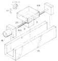
図1は、実施の形態の精密送り装置100が適用された表面粗さ測定機102を示す斜視図である。この表面粗さ測定機102は、測定部ベース104上に設置された位置調整装置106によって測定対象物108が位置調整されて取り付けられる。また、測定部ベース104にはコラム110が立設され、このコラム110に、送り装置100が内蔵された駆動装置112が上下(Z軸方向)移動自在に設けられている。送り装置100は送りねじ2、モータ116、及び不図示の送りナットが内設された移動側キャリッジ25からなり、この移動側キャリッジ25に、触針118が設けられた検出器120が連結されている。
【0019】
このように構成された表面粗さ測定機102によれば、駆動装置112をコラム110に沿って下降移動させて触針118を測定対象物108に接触させる。この後、送り装置100のモータ116を駆動して送りねじ2を回転させ、前記送りナットの推力により移動側キャリッジ25を水平(X方向)に移動させることにより、触針118を測定対象物108の上面に沿って移動させ、これによって触針118が上下(Z方向)に移動することにより、測定対象物108の粗さが検出器120によって測定される。
【0020】
表面粗さ測定機102では、触針118が上下に移動して粗さを測定するために、移動側キャリッジ25のZ軸方向の真直度が高いことが要求される。このため、移動側キャリッジ25に実施の形態の継手が内設されている。この継手については後述する。
【0021】
図2は、実施の形態の送り装置100が適用された真直度測定機122を示す斜視図であり、図3は送り装置100の組立斜視図である。真直度測定機122は、X軸送りステージ固定案内面1に沿って位置調整テーブル124がX軸方向に移動自在に設けられ、この位置調整テーブル124に測定対象物108が位置調整されて取り付けられる。また、X軸送りステージ固定案内面1が形成されたガイド部材1Bにはコラム126が立設され、このコラム126に、Z軸変位検出器128を介して触針130が設けられている。
【0022】
このように構成された真直度測定機122によれば、触針130を測定対象物108に接触させた後、送り装置100のモータ116を駆動して送りねじ2を回転させ、図3に示す送りナット3の推力により、位置調整テーブル124の下部に接続された移動側キャリッジ25をX軸方向に移動させる。これにより、Z軸変位検出器128によってZ軸方向の変位が測定され、測定対象物108のX−Z断面輪郭形状が得られる。
【0023】
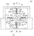
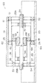
図4〜図9には、実施の形態の継手60の構造図が示されている。
【0024】
図2に示すように、X軸送りステージ固定案内面1が形成されたガイド1Bには、送りねじ2と継手部が移動できる逃げ溝(不図示)が形成され、図3の移動キャリッジ25は、位置調整テーブル124及び不図示の軸受を介してX軸送りステージ固定案内面1(図2参照)に滑動自在に支持される。送りねじ2に螺合された、図4に示す送りナット3は、送りナットハウジング4に固定される。送りナットハウジング4を挟んで、送りナットハウジング4の右方向と左方向に、すなわち、送りナットの移動方向両側に4枚の水平帯板ばね(第1の板ばね部材)5、6、35、36が4枚の水平帯板ばね押さえ7、8、37、38によって固定される。水平帯板ばね5、6は、送りねじ2を挟んで送りねじ2と平行に配設され、また、水平帯板ばね35、36も同様に配設されている。
【0025】
水平帯板ばね5、6、35、36は、各々表と裏が2枚の板ばね押さえ9、10、11、12、39、40、41、42により、その中間部分が補強され、更にそれらは中間部材15、34に各々1枚の水平板ばね押さえ13、14、43、44によって固定される。
【0026】
中間部材15、34には、更に鉛直帯板ばね(第2の板ばね部材)17、18、26、27が各々1枚の鉛直板ばね押さえ23、24、32、33によって固定される。鉛直帯板ばね17、18、26、27は、各々表と裏が2枚の板ばね押さえ19、20、21、22、28、29、30、31により、その中間部分が補強され、更にそれらは移動キャリッジ25の両側に配置された側壁25A、25Bに所定の張力をもって固定される。鉛直帯板ばね17、18は、送りねじ2を挟んで送りねじ2と平行に配設され、また、鉛直帯板ばね26、27も同様に配設されている。
【0027】
このように構成された継手60によれば、その面が水平方向に向いた水平帯板ばね5、6、35、36と、その面が鉛直方向に向いた鉛直帯板ばね17、18、26、27とを、中間部材15、34を介して移動側キャリッジ25に所定の張力をもって設けることにより、送りに垂直な方向への変位に対し、水平帯板ばね5、6、35、36及び鉛直帯板ばね17、18、26、27が弾性変形することにより、その変位を摩擦力無しで吸収し、移動側キャリッジ25に対する前記変位の伝達を遮断できる。また、水平帯板ばね5、6、35、36及び鉛直帯板ばね17、18、26、27を適用することによって、送り方向の剛性を格段に向上させることができるとともに、送りねじ2による送り方向に垂直な振れやピッチング誤差を吸収できる。
【0028】
また、水平帯板ばね5、6、35、36と鉛直帯板ばね17、18、26、27とを、送りナット3を挟んで両側に夫々一対設け、これらの水平帯板ばね5、6、35、36及び鉛直帯板ばね17、18、26、27を送りねじ2を挟んで送りねじ2と平行に並設したので、送りねじ2に直交する方向の振れを確実に吸収できる。
【0029】
更に、図7、図8に示すように、水平帯板ばね5、6、35、36及び鉛直帯板ばね17、18、26、27の各面の延長線5A、6A、35A、36A、17A、18A、26A、27Aが送りねじ2の中心2Aに向くように、これらの水平帯板ばね5、6、35、36及び鉛直帯板ばね17、18、26、27を配置したので、送りナット2のピッチングを吸収できる。
【0030】
ところで、実施の形態の継手60は図4に示すように、鉛直帯板ばね17、18、26、27が連結される中間部材15、34の連結部62、64、66、68が送りナット3に向けて突出形成されている。また、これらの連結部62、64、66、68は、水平帯板ばね5、6、35、36が連結される送りナット3側の送りナットハウジング4の連結部70、72、74、76と送りねじ2に直交する、図5上二点鎖線で示す面78に対し略同一面上に位置されている。
【0031】
このように、鉛直帯板ばね17、18、26、27が連結される中間部材15、34の連結部62、64、66、68を、送りナット3側に突出させた構造によって、継手60の等価実行長さを移動側キャリッジ25の長さより長くとることができるので、継手60の横の変位、傾斜に対する吸収機能が向上する。
【0032】
また、連結部62、64、66、68と連結部70、72、74、76とを送りねじ2に直交する面78に対し略同一面上に位置させたので、送りナット3のピッチングを吸収できる。
【0033】
更に、水平帯板ばね5、6、35、36は、移動キャリッジ25の摺動力重心と同一高さの面内に配置されているので、ピッチング変位を引き起こす偶力が低減されている。
【0034】
また、左右の水平帯板ばね5、6、35、36の移動キャリッジ25側の揺動中心を送り方向について略同一位置に配置することで、送りナット3にピッチング変化が生じても、それによって、移動キャリッジ25にピッチング方向の偶力が働かないようになっている。
【0035】
鉛直帯板ばね17、18、26、27は、駆動方向に垂直でX軸送りステージ固定案内面1に平行な方向への変位と傾き(ヨーイング)に対して逃げるので、この方向の力が案内面1に伝達するのを防止できる。
【0036】
なお、実施の形態では、前述の如く、連結部62、64、66、68と連結部70、72、74、76とを送りねじ2に直交する面78に対し略同一面上に位置させたが、これに限定されるものではない。すなわち、連結部62、64、66、68と連結部70、72、74、76とを水平方向にずらして形成しても、表面粗さ測定機102には測定精度上支障を与えない。すなわち、表面粗さ測定機102においては、送りナット3のZ軸方向の変位が測定誤差に起因するため、前記ずらした構造を採用した場合でも、Z軸方向の変位を摩擦力無しで十分に吸収する。よって、測定精度に支障を与えず、測定精度が向上する。
【0037】
【発明の効果】
以上説明したように本発明に係る送り装置の継手によれば、その面が一方向側と他方向側とに向いた板ばね部材を、中間部材を介して移動部材に設けることにより、送りに垂直な方向への変位に対し、板ばね部材が弾性変形することにより、移動部材に対する前記変位の伝達を遮断できる。また、板ばね部材を適用することによって、送り方向の剛性が格段に向上するとともに、送りねじによる送り方向に垂直な振れやピッチング誤差を吸収できる。
【0038】
また、本発明によれば、第2の板ばね部材が連結される中間部材の連結部を、送りナット側に突出させた構造によって、継手の等価実行長さを移動部材の長さより長くとることができるので、継手の横の変位、傾斜に対する吸収機能が向上する。また、第2の板ばね部材が連結される中間部材の連結部と、第1の板ばね部材が連結される送りナット側の連結部とを、送りねじに直交する面に対し同一面上に位置させたので、送りナットのピッチングを吸収できる。
【図面の簡単な説明】
【図1】実施の形態の精密送り装置の継手が適用された表面粗さ測定機の斜視図
【図2】実施の形態の精密送り装置の継手が適用された真直度測定機の斜視図
【図3】図2に示した真直度測定機の精密送り装置の組立斜視図
【図4】実施の形態の精密送り装置の継手の組立斜視図
【図5】帯板ばねを除いた精密送り装置の継手の構造を示す斜視図
【図6】精密送り装置の継手の構造を示す平面図
【図7】図6の7−7線から見た継手の側面図
【図8】図6の8−8線から見た継手の側面図
【図9】図6に示した精密送り装置の継手の側面図
【符号の説明】
1…X軸送りステージ固定案内面、2…送りねじ、3…ナット、4…ナットハウジング、25…移動側キャリッジ、5、6、35、36…水平帯板ばね、7、8、37、38…水平帯板ばね押さえ、9、10、11、12、39、40、41、42…板ばね押さえ、15、34…中間部材、13、14、43、44…水平板ばね押さえ、17、18、26、27…鉛直帯板ばね、23、24、32、33…鉛直板ばね押さえ、19、20、21、22、28、29、30、31…板ばね押さえ、60…継手、100…送り装置、102…表面粗さ測定機、122…真直度測定機[0001]
BACKGROUND OF THE INVENTION
The present invention relates to a joint for a feeding device used in precision measuring machines such as a surface roughness measuring machine and a straightness measuring machine.
[0002]
[Prior art]
In precision feeding devices used in precision measuring machines such as surface roughness measuring machines and straightness measuring machines, the displacement in one direction perpendicular to the guide (movement) direction of the stylus is measured. High feed straightness and feed pitching angle accuracy are required.
[0003]
When a feed device having a feed screw, such as a feed screw or a ball screw, is applied as such a precision feed device, a feed screwed to the feed screw on a moving carriage (moving member) provided with a stylus is provided. It is common to directly fix the nut. However, there is a problem that the feed straightness fluctuates for each rotation of the feed screw due to the feed screw runout. When high straightness accuracy is required, it is necessary to eliminate this effect, so the feed nut is connected to the moving carriage via an Oldham coupling or wire, and the feed nut caused by the feed screw is connected by the Oldham coupling or wire. Absorbed the shake.
[0004]
[Problems to be solved by the invention]
However, when the Oldham coupling is used, it is possible to absorb vibrations in all directions orthogonal to the feed direction, but there is a problem that frictional force is generated due to the shake and backlash in the feed direction remains.
[0005]
Also, in order to reduce the force caused by the deflection in the direction perpendicular to the guide direction by the wire, it is necessary to reduce the wire diameter and lower the tension, but this will reduce the rigidity in the feed direction, so the thrust of the feed nut will move. There was a problem that it could not be transmitted to the carriage.
[0006]
Further, these joints can absorb the displacement of the tilt component as well as the displacement of the horizontal and vertical translation components, but the rotation errors such as pitching and yawing are not sufficiently removed. If it is intentionally made a flexible structure, it can be removed, but there is a problem that the rigidity in the important feed direction cannot be secured. Furthermore, in order to eliminate the frictional force caused by motion, which is a problem with Oldham joints, it is conceivable to use hydrostatic air bearings or magnetic bearings. It was.
[0007]
The present invention has been made in view of the above circumstances, and prevents vertical displacement and pitching and yawing errors of the feed screw due to the feed screw from being transmitted to the moving member. An object of the present invention is to provide a feeder joint having high rigidity.
[0008]
[Means for Solving the Problems]
In order to achieve the above object, the present invention provides a joint of a feed device that connects a feed nut screwed to a feed screw and a moving member, wherein the joint is moved in the direction of movement of the moving member across the feed nut. Located on both sides, one end is connected to the feed nut and the other end is connected to an intermediate member, and the deflection of the feed nut in the direction perpendicular to the feed screw is elastic to one side. One end of the first leaf spring member that is deformed and absorbed, and one end of the intermediate member are connected to the moving member, and the other end is connected to the moving member, and the feed nut swings in a direction perpendicular to the feed screw. A second leaf spring member that elastically deforms and absorbs vibration in the other direction orthogonal to the one direction side, and the intermediate member coupling portion to which the second leaf spring member is coupled Protrudes toward the feed nut Both are characterized by being positioned on substantially the same plane with respect to a plane perpendicular to the axis of the first connecting portion of the feed nut side and the leaf spring member is connected the feed screw.
[0009]
According to the first aspect of the present invention, the leaf spring member whose surface is oriented in the horizontal direction (one direction) and the vertical direction (the other direction) is provided on the moving member via the intermediate member, thereby perpendicular to the feed direction. When the leaf spring member is elastically deformed with respect to a displacement in any direction, the displacement is absorbed without frictional force, and the transmission of the displacement to the moving member is cut off.
[0010]
In addition, by applying a leaf spring member, the rigidity in the feed direction is significantly improved compared to conventional joints that use wires such as wires. Can prevent transmission.
[0011]
Further, in the Oldham joint, a frictional force acts when escaping in the vertical direction, and displacement transmission remains. Further, when a static pressure type air bearing or a magnetic bearing is used, the clearance and rigidity in the pitching direction are insufficient, but this leaf spring type joint can satisfy these conflicting requirements.
[0012]
The leaf spring can achieve a tensile rigidity determined by the Young's modulus in the tensile direction, but has a characteristic that the rigidity becomes extremely low due to buckling against a force in the compression direction.
[0013]
In order to avoid this decrease in rigidity, the joints are arranged on both sides of the moving member in the moving direction and connected to the feed nut from both sides. When the feed nut is driven to the left side, a tensile force acts on the right joint, and the displacement of the feed nut is transmitted to the moving member in a state of high rigidity. On the other hand, when the feed nut is driven to the right side, similarly, a pulling force acts on the left joint, and the displacement of the feed nut is transmitted to the moving member in a state of high rigidity.
[0014]
Further, if a pair of the first leaf spring member and the second leaf spring member are provided and these leaf spring members are arranged in parallel with the feed screw with the feed screw interposed therebetween, both directions on one side and the other side are provided. Can reliably absorb the fluctuations. Moreover, the pitching of the feed nut can be absorbed by arranging these leaf spring members so that the extension line of the surface of these leaf spring members faces the center of the feed screw.
[0015]
According to the onset bright, the connecting portion of the intermediate member is a second leaf spring member is connected, together protrudes toward the feed nut, the feed nut the first plate spring member is connected It is characterized in that it is positioned on substantially the same plane with respect to a plane orthogonal to the connecting portion on the side and the axis of the feed screw.
[0016]
In this way, the equivalent execution length of the joint can be made longer than the length of the moving member by the structure in which the connecting portion of the intermediate member to which the second leaf spring member is connected protrudes to the feed nut side. Absorption function against lateral displacement and inclination of the joint is improved. Further, the connecting portion of the intermediate member to which the second leaf spring member is connected and the connecting portion of the feed nut to which the first leaf spring member is connected are located on the same plane with respect to the surface orthogonal to the feed screw. As a result, the pitching of the feed nut can be absorbed.
[0017]
DETAILED DESCRIPTION OF THE INVENTION
The preferred embodiments of the joint of the feeder according to the present invention will be described in detail below with reference to the accompanying drawings.
[0018]
FIG. 1 is a perspective view showing a surface
[0019]
According to the surface
[0020]
The surface
[0021]
FIG. 2 is a perspective view showing a
[0022]
According to the
[0023]
FIGS. 4 to 9 show structural diagrams of the joint 60 according to the embodiment.
[0024]
As shown in FIG. 2 , the guide 1B on which the X-axis feed stage fixed guide surface 1 is formed has a relief groove (not shown) through which the
[0025]
The horizontal
[0026]
Further, vertical strip leaf springs (second leaf spring members) 17, 18, 26, and 27 are fixed to the
[0027]
According to the joint 60 configured in this way, the horizontal strip springs 5, 6, 35, and 36 whose surfaces are directed in the horizontal direction, and the vertical strip springs 17, 18, and 26 whose surfaces are directed in the vertical direction. , 27 with the predetermined tension on the moving
[0028]
In addition, a pair of horizontal strip springs 5, 6, 35, 36 and vertical strip springs 17, 18, 26, 27 are provided on both sides of the
[0029]
Further, as shown in FIGS. 7 and 8, the extension lines 5A, 6A, 35A, 36A, 17A of the surfaces of the horizontal strip springs 5, 6, 35, 36 and the vertical strip springs 17, 18, 26, 27 are provided. , 18A, 26A, 27A are disposed so that the horizontal
[0030]
By the way, in the joint 60 of the embodiment, as shown in FIG. 4, the connecting
[0031]
As described above, the connecting
[0032]
Further, since the connecting
[0033]
Furthermore, since the horizontal strip springs 5, 6, 35, and 36 are disposed in a plane having the same height as the gravity center of the sliding force of the
[0034]
Further, by arranging the swing center of the left and right horizontal strip springs 5, 6, 35, 36 on the
[0035]
The vertical strip springs 17, 18, 26, 27 escape against displacement and inclination (yawing) in a direction perpendicular to the driving direction and parallel to the X-axis feed stage fixed guide surface 1, so that the force in this direction is guided. Transmission to the surface 1 can be prevented.
[0036]
In the embodiment, as described above, the connecting
[0037]
【The invention's effect】
As described above, according to the joint of the feeding device according to the present invention, the leaf spring member whose surface is directed to the one direction side and the other direction side is provided on the moving member via the intermediate member. When the leaf spring member is elastically deformed with respect to the displacement in the vertical direction, transmission of the displacement to the moving member can be cut off. Further, by applying the leaf spring member, the rigidity in the feed direction is remarkably improved, and vibrations and pitching errors perpendicular to the feed direction by the feed screw can be absorbed.
[0038]
Further, according to the present invention, the equivalent effective length of the joint is made longer than the length of the moving member by the structure in which the connecting portion of the intermediate member to which the second leaf spring member is connected protrudes to the feed nut side. Therefore, the absorption function with respect to the lateral displacement and inclination of the joint is improved. Further, the connecting portion of the intermediate member to which the second leaf spring member is connected and the connecting portion on the feed nut side to which the first leaf spring member is connected are on the same plane with respect to the surface orthogonal to the feed screw. Because it is positioned, the pitching of the feed nut can be absorbed.
[Brief description of the drawings]
FIG. 1 is a perspective view of a surface roughness measuring machine to which a joint of the precision feeding device of the embodiment is applied. FIG. 2 is a perspective view of a straightness measuring machine to which the joint of the precision feeding device of the embodiment is applied. 3 is an assembled perspective view of the precision feeding device of the straightness measuring machine shown in FIG. 2. FIG. 4 is an assembled perspective view of a joint of the precision feeding device of the embodiment. FIG. FIG. 6 is a plan view showing the structure of the joint of the precision feeding device. FIG. 7 is a side view of the joint as viewed from line 7-7 in FIG. 6. FIG. Side view of the joint as seen from line 8 [FIG. 9] Side view of the joint of the precision feeder shown in FIG.
DESCRIPTION OF SYMBOLS 1 ... X-axis feed stage fixed guide surface, 2 ... Feed screw, 3 ... Nut, 4 ... Nut housing, 25 ... Moving side carriage, 5, 6, 35, 36 ... Horizontal strip spring, 7, 8, 37, 38 ... Horizontal leaf spring retainer, 9, 10, 11, 12, 39, 40, 41, 42 ... Leaf spring retainer, 15, 34 ... Intermediate member, 13, 14, 43, 44 ... Horizontal leaf spring retainer, 17, 18 , 26, 27 ... vertical strip springs, 23, 24, 32, 33 ... vertical leaf spring retainers, 19, 20, 21, 22, 28, 29, 30, 31 ... leaf spring retainers, 60 ... joints, 100 ... feed
Claims (1)
該継手は、前記送りナットを挟んで前記移動部材の移動方向両側に配置され、前記送りナットに一端部が連結されるとともに、他端部が中間部材に連結され、前記送りねじに対し垂直な方向の送りナットの振れのうち、一方向側の振れを弾性変形して吸収する第1の板ばね部材と、
前記中間部材に一端部が連結されるとともに、他端部が前記移動部材に連結され、前記送りねじに対し垂直な方向の送りナットの振れのうち、前記一方向側に直交する他方向側の振れを弾性変形して吸収する第2の板ばね部材と、を有し、
前記第2の板ばね部材が連結される前記中間部材の連結部は、前記送りナットに向けて突出されるとともに、前記第1の板ばね部材が連結される送りナット側の連結部と前記送りねじの軸線に直交する面に対し略同一面上に位置されていることを特徴とする送り装置の継手。In the joint of the feed device that connects the feed nut screwed to the feed screw and the moving member,
The joint is disposed on both sides of the moving member in the moving direction across the feed nut, and one end is connected to the feed nut and the other end is connected to an intermediate member, and is perpendicular to the feed screw. A first leaf spring member that elastically deforms and absorbs one-side vibration among the directional feed nut vibrations;
One end is connected to the intermediate member, the other end is connected to the moving member, and the other side of the feed nut in a direction perpendicular to the feed screw is perpendicular to the one direction. A second leaf spring member that elastically deforms and absorbs vibration ,
A connecting portion of the intermediate member to which the second leaf spring member is connected protrudes toward the feed nut, and a connecting portion on the feed nut side to which the first leaf spring member is connected and the feed. A joint for a feeding device, wherein the joint is located on substantially the same plane with respect to a plane perpendicular to the axis of the screw .
Priority Applications (1)
| Application Number | Priority Date | Filing Date | Title |
|---|---|---|---|
| JP2002204017A JP4189796B2 (en) | 2002-07-12 | 2002-07-12 | Feeder fitting |
Applications Claiming Priority (1)
| Application Number | Priority Date | Filing Date | Title |
|---|---|---|---|
| JP2002204017A JP4189796B2 (en) | 2002-07-12 | 2002-07-12 | Feeder fitting |
Publications (3)
| Publication Number | Publication Date |
|---|---|
| JP2004044710A JP2004044710A (en) | 2004-02-12 |
| JP2004044710A5 JP2004044710A5 (en) | 2005-09-29 |
| JP4189796B2 true JP4189796B2 (en) | 2008-12-03 |
Family
ID=31709725
Family Applications (1)
| Application Number | Title | Priority Date | Filing Date |
|---|---|---|---|
| JP2002204017A Expired - Fee Related JP4189796B2 (en) | 2002-07-12 | 2002-07-12 | Feeder fitting |
Country Status (1)
| Country | Link |
|---|---|
| JP (1) | JP4189796B2 (en) |
Families Citing this family (1)
| Publication number | Priority date | Publication date | Assignee | Title |
|---|---|---|---|---|
| JP7092469B2 (en) | 2017-06-29 | 2022-06-28 | 日本電産サンキョー株式会社 | Industrial robot hand and industrial robot |
-
2002
- 2002-07-12 JP JP2002204017A patent/JP4189796B2/en not_active Expired - Fee Related
Also Published As
| Publication number | Publication date |
|---|---|
| JP2004044710A (en) | 2004-02-12 |
Similar Documents
| Publication | Publication Date | Title |
|---|---|---|
| JPH095464A (en) | Support mechanism | |
| JP2006194909A (en) | Apparatus for measuring surface properties | |
| JP2776427B2 (en) | Coordinate measuring machine | |
| KR100659524B1 (en) | Axis connecting structure | |
| US7210239B2 (en) | Slider device and measuring instrument | |
| JP4189796B2 (en) | Feeder fitting | |
| CN108534731B (en) | Lifting driving device and measuring machine adopting same | |
| JPH0611435Y2 (en) | Table feed mechanism | |
| JP5172556B2 (en) | Synchronous moving device and image measuring device | |
| KR101218772B1 (en) | stage with flexure joint for compensation of yaw error | |
| JPH10186198A (en) | Parallel and straight fine adjustment device and fine moving device of lens barrel using the same | |
| CN108614395B (en) | Parallel motion mechanism based on shaft flexible hinge adjusts device | |
| US5301933A (en) | Sample moving device | |
| JP2837756B2 (en) | Positioning stage | |
| JP2007278377A (en) | Feeder joint | |
| JPH0794961B2 (en) | Measuring instrument drive connection device | |
| JP3184371B2 (en) | Single plate type XY table device | |
| JPH0885026A (en) | Gantry driving device | |
| CN113386173B (en) | Torque measuring device | |
| JP2797640B2 (en) | Carriage moving device and automatic processing device | |
| JP2000298186A (en) | Positioning stage | |
| JP6390070B2 (en) | CMM | |
| JPH10154012A (en) | Stage mechanism | |
| JP2021092590A (en) | Three-dimensional coordinate measurement device | |
| JPS6085848A (en) | Linearly movable table |
Legal Events
| Date | Code | Title | Description |
|---|---|---|---|
| A521 | Written amendment |
Free format text: JAPANESE INTERMEDIATE CODE: A523 Effective date: 20050422 |
|
| A621 | Written request for application examination |
Free format text: JAPANESE INTERMEDIATE CODE: A621 Effective date: 20050422 |
|
| A977 | Report on retrieval |
Free format text: JAPANESE INTERMEDIATE CODE: A971007 Effective date: 20080327 |
|
| A131 | Notification of reasons for refusal |
Free format text: JAPANESE INTERMEDIATE CODE: A131 Effective date: 20080403 |
|
| A521 | Written amendment |
Free format text: JAPANESE INTERMEDIATE CODE: A523 Effective date: 20080527 |
|
| TRDD | Decision of grant or rejection written | ||
| A01 | Written decision to grant a patent or to grant a registration (utility model) |
Free format text: JAPANESE INTERMEDIATE CODE: A01 Effective date: 20080822 |
|
| A01 | Written decision to grant a patent or to grant a registration (utility model) |
Free format text: JAPANESE INTERMEDIATE CODE: A01 |
|
| A61 | First payment of annual fees (during grant procedure) |
Free format text: JAPANESE INTERMEDIATE CODE: A61 Effective date: 20080904 |
|
| FPAY | Renewal fee payment (event date is renewal date of database) |
Free format text: PAYMENT UNTIL: 20110926 Year of fee payment: 3 |
|
| R150 | Certificate of patent or registration of utility model |
Free format text: JAPANESE INTERMEDIATE CODE: R150 |
|
| FPAY | Renewal fee payment (event date is renewal date of database) |
Free format text: PAYMENT UNTIL: 20120926 Year of fee payment: 4 |
|
| FPAY | Renewal fee payment (event date is renewal date of database) |
Free format text: PAYMENT UNTIL: 20130926 Year of fee payment: 5 |
|
| R250 | Receipt of annual fees |
Free format text: JAPANESE INTERMEDIATE CODE: R250 |
|
| R250 | Receipt of annual fees |
Free format text: JAPANESE INTERMEDIATE CODE: R250 |
|
| R250 | Receipt of annual fees |
Free format text: JAPANESE INTERMEDIATE CODE: R250 |
|
| R250 | Receipt of annual fees |
Free format text: JAPANESE INTERMEDIATE CODE: R250 |
|
| LAPS | Cancellation because of no payment of annual fees |