JP4188422B2 - Apparatus and method for molding polyester articles directly from melt - Google Patents
Apparatus and method for molding polyester articles directly from melt Download PDFInfo
- Publication number
- JP4188422B2 JP4188422B2 JP54079798A JP54079798A JP4188422B2 JP 4188422 B2 JP4188422 B2 JP 4188422B2 JP 54079798 A JP54079798 A JP 54079798A JP 54079798 A JP54079798 A JP 54079798A JP 4188422 B2 JP4188422 B2 JP 4188422B2
- Authority
- JP
- Japan
- Prior art keywords
- polyester
- molten
- pumping means
- barrel
- flow
- Prior art date
- Legal status (The legal status is an assumption and is not a legal conclusion. Google has not performed a legal analysis and makes no representation as to the accuracy of the status listed.)
- Expired - Lifetime
Links
Images

Classifications
-
- C—CHEMISTRY; METALLURGY
- C08—ORGANIC MACROMOLECULAR COMPOUNDS; THEIR PREPARATION OR CHEMICAL WORKING-UP; COMPOSITIONS BASED THEREON
- C08G—MACROMOLECULAR COMPOUNDS OBTAINED OTHERWISE THAN BY REACTIONS ONLY INVOLVING UNSATURATED CARBON-TO-CARBON BONDS
- C08G63/00—Macromolecular compounds obtained by reactions forming a carboxylic ester link in the main chain of the macromolecule
- C08G63/78—Preparation processes
- C08G63/785—Preparation processes characterised by the apparatus used
-
- B—PERFORMING OPERATIONS; TRANSPORTING
- B29—WORKING OF PLASTICS; WORKING OF SUBSTANCES IN A PLASTIC STATE IN GENERAL
- B29B—PREPARATION OR PRETREATMENT OF THE MATERIAL TO BE SHAPED; MAKING GRANULES OR PREFORMS; RECOVERY OF PLASTICS OR OTHER CONSTITUENTS OF WASTE MATERIAL CONTAINING PLASTICS
- B29B17/00—Recovery of plastics or other constituents of waste material containing plastics
- B29B17/0005—Direct recuperation and re-use of scrap material during moulding operation, i.e. feed-back of used material
-
- B—PERFORMING OPERATIONS; TRANSPORTING
- B29—WORKING OF PLASTICS; WORKING OF SUBSTANCES IN A PLASTIC STATE IN GENERAL
- B29C—SHAPING OR JOINING OF PLASTICS; SHAPING OF MATERIAL IN A PLASTIC STATE, NOT OTHERWISE PROVIDED FOR; AFTER-TREATMENT OF THE SHAPED PRODUCTS, e.g. REPAIRING
- B29C45/00—Injection moulding, i.e. forcing the required volume of moulding material through a nozzle into a closed mould; Apparatus therefor
- B29C45/17—Component parts, details or accessories; Auxiliary operations
- B29C45/18—Feeding the material into the injection moulding apparatus, i.e. feeding the non-plastified material into the injection unit
- B29C45/1816—Feeding auxiliary material, e.g. colouring material
-
- B—PERFORMING OPERATIONS; TRANSPORTING
- B29—WORKING OF PLASTICS; WORKING OF SUBSTANCES IN A PLASTIC STATE IN GENERAL
- B29C—SHAPING OR JOINING OF PLASTICS; SHAPING OF MATERIAL IN A PLASTIC STATE, NOT OTHERWISE PROVIDED FOR; AFTER-TREATMENT OF THE SHAPED PRODUCTS, e.g. REPAIRING
- B29C45/00—Injection moulding, i.e. forcing the required volume of moulding material through a nozzle into a closed mould; Apparatus therefor
- B29C45/17—Component parts, details or accessories; Auxiliary operations
- B29C45/46—Means for plasticising or homogenising the moulding material or forcing it into the mould
- B29C45/53—Means for plasticising or homogenising the moulding material or forcing it into the mould using injection ram or piston
- B29C45/54—Means for plasticising or homogenising the moulding material or forcing it into the mould using injection ram or piston and plasticising screw
-
- B—PERFORMING OPERATIONS; TRANSPORTING
- B29—WORKING OF PLASTICS; WORKING OF SUBSTANCES IN A PLASTIC STATE IN GENERAL
- B29C—SHAPING OR JOINING OF PLASTICS; SHAPING OF MATERIAL IN A PLASTIC STATE, NOT OTHERWISE PROVIDED FOR; AFTER-TREATMENT OF THE SHAPED PRODUCTS, e.g. REPAIRING
- B29C45/00—Injection moulding, i.e. forcing the required volume of moulding material through a nozzle into a closed mould; Apparatus therefor
- B29C45/17—Component parts, details or accessories; Auxiliary operations
- B29C45/46—Means for plasticising or homogenising the moulding material or forcing it into the mould
- B29C45/58—Details
- B29C45/63—Venting or degassing means
-
- B—PERFORMING OPERATIONS; TRANSPORTING
- B29—WORKING OF PLASTICS; WORKING OF SUBSTANCES IN A PLASTIC STATE IN GENERAL
- B29C—SHAPING OR JOINING OF PLASTICS; SHAPING OF MATERIAL IN A PLASTIC STATE, NOT OTHERWISE PROVIDED FOR; AFTER-TREATMENT OF THE SHAPED PRODUCTS, e.g. REPAIRING
- B29C48/00—Extrusion moulding, i.e. expressing the moulding material through a die or nozzle which imparts the desired form; Apparatus therefor
- B29C48/022—Extrusion moulding, i.e. expressing the moulding material through a die or nozzle which imparts the desired form; Apparatus therefor characterised by the choice of material
-
- B—PERFORMING OPERATIONS; TRANSPORTING
- B29—WORKING OF PLASTICS; WORKING OF SUBSTANCES IN A PLASTIC STATE IN GENERAL
- B29C—SHAPING OR JOINING OF PLASTICS; SHAPING OF MATERIAL IN A PLASTIC STATE, NOT OTHERWISE PROVIDED FOR; AFTER-TREATMENT OF THE SHAPED PRODUCTS, e.g. REPAIRING
- B29C48/00—Extrusion moulding, i.e. expressing the moulding material through a die or nozzle which imparts the desired form; Apparatus therefor
- B29C48/25—Component parts, details or accessories; Auxiliary operations
- B29C48/36—Means for plasticising or homogenising the moulding material or forcing it through the nozzle or die
- B29C48/365—Means for plasticising or homogenising the moulding material or forcing it through the nozzle or die using pumps, e.g. piston pumps
- B29C48/37—Gear pumps
-
- B—PERFORMING OPERATIONS; TRANSPORTING
- B29—WORKING OF PLASTICS; WORKING OF SUBSTANCES IN A PLASTIC STATE IN GENERAL
- B29C—SHAPING OR JOINING OF PLASTICS; SHAPING OF MATERIAL IN A PLASTIC STATE, NOT OTHERWISE PROVIDED FOR; AFTER-TREATMENT OF THE SHAPED PRODUCTS, e.g. REPAIRING
- B29C48/00—Extrusion moulding, i.e. expressing the moulding material through a die or nozzle which imparts the desired form; Apparatus therefor
- B29C48/25—Component parts, details or accessories; Auxiliary operations
- B29C48/36—Means for plasticising or homogenising the moulding material or forcing it through the nozzle or die
- B29C48/375—Plasticisers, homogenisers or feeders comprising two or more stages
- B29C48/387—Plasticisers, homogenisers or feeders comprising two or more stages using a screw extruder and a gear pump
-
- B—PERFORMING OPERATIONS; TRANSPORTING
- B29—WORKING OF PLASTICS; WORKING OF SUBSTANCES IN A PLASTIC STATE IN GENERAL
- B29C—SHAPING OR JOINING OF PLASTICS; SHAPING OF MATERIAL IN A PLASTIC STATE, NOT OTHERWISE PROVIDED FOR; AFTER-TREATMENT OF THE SHAPED PRODUCTS, e.g. REPAIRING
- B29C48/00—Extrusion moulding, i.e. expressing the moulding material through a die or nozzle which imparts the desired form; Apparatus therefor
- B29C48/25—Component parts, details or accessories; Auxiliary operations
- B29C48/36—Means for plasticising or homogenising the moulding material or forcing it through the nozzle or die
- B29C48/375—Plasticisers, homogenisers or feeders comprising two or more stages
- B29C48/388—Plasticisers, homogenisers or feeders comprising two or more stages using a screw extruder and a ram or piston
-
- B—PERFORMING OPERATIONS; TRANSPORTING
- B29—WORKING OF PLASTICS; WORKING OF SUBSTANCES IN A PLASTIC STATE IN GENERAL
- B29C—SHAPING OR JOINING OF PLASTICS; SHAPING OF MATERIAL IN A PLASTIC STATE, NOT OTHERWISE PROVIDED FOR; AFTER-TREATMENT OF THE SHAPED PRODUCTS, e.g. REPAIRING
- B29C48/00—Extrusion moulding, i.e. expressing the moulding material through a die or nozzle which imparts the desired form; Apparatus therefor
- B29C48/25—Component parts, details or accessories; Auxiliary operations
- B29C48/36—Means for plasticising or homogenising the moulding material or forcing it through the nozzle or die
- B29C48/395—Means for plasticising or homogenising the moulding material or forcing it through the nozzle or die using screws surrounded by a cooperating barrel, e.g. single screw extruders
-
- B—PERFORMING OPERATIONS; TRANSPORTING
- B29—WORKING OF PLASTICS; WORKING OF SUBSTANCES IN A PLASTIC STATE IN GENERAL
- B29C—SHAPING OR JOINING OF PLASTICS; SHAPING OF MATERIAL IN A PLASTIC STATE, NOT OTHERWISE PROVIDED FOR; AFTER-TREATMENT OF THE SHAPED PRODUCTS, e.g. REPAIRING
- B29C67/00—Shaping techniques not covered by groups B29C39/00 - B29C65/00, B29C70/00 or B29C73/00
- B29C67/24—Shaping techniques not covered by groups B29C39/00 - B29C65/00, B29C70/00 or B29C73/00 characterised by the choice of material
- B29C67/246—Moulding high reactive monomers or prepolymers, e.g. by reaction injection moulding [RIM], liquid injection moulding [LIM]
-
- C—CHEMISTRY; METALLURGY
- C08—ORGANIC MACROMOLECULAR COMPOUNDS; THEIR PREPARATION OR CHEMICAL WORKING-UP; COMPOSITIONS BASED THEREON
- C08G—MACROMOLECULAR COMPOUNDS OBTAINED OTHERWISE THAN BY REACTIONS ONLY INVOLVING UNSATURATED CARBON-TO-CARBON BONDS
- C08G63/00—Macromolecular compounds obtained by reactions forming a carboxylic ester link in the main chain of the macromolecule
- C08G63/78—Preparation processes
-
- B—PERFORMING OPERATIONS; TRANSPORTING
- B29—WORKING OF PLASTICS; WORKING OF SUBSTANCES IN A PLASTIC STATE IN GENERAL
- B29C—SHAPING OR JOINING OF PLASTICS; SHAPING OF MATERIAL IN A PLASTIC STATE, NOT OTHERWISE PROVIDED FOR; AFTER-TREATMENT OF THE SHAPED PRODUCTS, e.g. REPAIRING
- B29C45/00—Injection moulding, i.e. forcing the required volume of moulding material through a nozzle into a closed mould; Apparatus therefor
- B29C45/17—Component parts, details or accessories; Auxiliary operations
- B29C45/18—Feeding the material into the injection moulding apparatus, i.e. feeding the non-plastified material into the injection unit
- B29C2045/1883—Feeding the material into the injection moulding apparatus, i.e. feeding the non-plastified material into the injection unit directly injecting moulding material from the chemical production plant into the mould without granulating
-
- B—PERFORMING OPERATIONS; TRANSPORTING
- B29—WORKING OF PLASTICS; WORKING OF SUBSTANCES IN A PLASTIC STATE IN GENERAL
- B29C—SHAPING OR JOINING OF PLASTICS; SHAPING OF MATERIAL IN A PLASTIC STATE, NOT OTHERWISE PROVIDED FOR; AFTER-TREATMENT OF THE SHAPED PRODUCTS, e.g. REPAIRING
- B29C45/00—Injection moulding, i.e. forcing the required volume of moulding material through a nozzle into a closed mould; Apparatus therefor
- B29C45/17—Component parts, details or accessories; Auxiliary operations
- B29C45/46—Means for plasticising or homogenising the moulding material or forcing it into the mould
- B29C45/53—Means for plasticising or homogenising the moulding material or forcing it into the mould using injection ram or piston
- B29C45/54—Means for plasticising or homogenising the moulding material or forcing it into the mould using injection ram or piston and plasticising screw
- B29C2045/545—Means for plasticising or homogenising the moulding material or forcing it into the mould using injection ram or piston and plasticising screw alternately operating injection plungers
-
- B—PERFORMING OPERATIONS; TRANSPORTING
- B29—WORKING OF PLASTICS; WORKING OF SUBSTANCES IN A PLASTIC STATE IN GENERAL
- B29C—SHAPING OR JOINING OF PLASTICS; SHAPING OF MATERIAL IN A PLASTIC STATE, NOT OTHERWISE PROVIDED FOR; AFTER-TREATMENT OF THE SHAPED PRODUCTS, e.g. REPAIRING
- B29C48/00—Extrusion moulding, i.e. expressing the moulding material through a die or nozzle which imparts the desired form; Apparatus therefor
- B29C48/03—Extrusion moulding, i.e. expressing the moulding material through a die or nozzle which imparts the desired form; Apparatus therefor characterised by the shape of the extruded material at extrusion
-
- B—PERFORMING OPERATIONS; TRANSPORTING
- B29—WORKING OF PLASTICS; WORKING OF SUBSTANCES IN A PLASTIC STATE IN GENERAL
- B29K—INDEXING SCHEME ASSOCIATED WITH SUBCLASSES B29B, B29C OR B29D, RELATING TO MOULDING MATERIALS OR TO MATERIALS FOR MOULDS, REINFORCEMENTS, FILLERS OR PREFORMED PARTS, e.g. INSERTS
- B29K2067/00—Use of polyesters or derivatives thereof, as moulding material
-
- B—PERFORMING OPERATIONS; TRANSPORTING
- B29—WORKING OF PLASTICS; WORKING OF SUBSTANCES IN A PLASTIC STATE IN GENERAL
- B29K—INDEXING SCHEME ASSOCIATED WITH SUBCLASSES B29B, B29C OR B29D, RELATING TO MOULDING MATERIALS OR TO MATERIALS FOR MOULDS, REINFORCEMENTS, FILLERS OR PREFORMED PARTS, e.g. INSERTS
- B29K2105/00—Condition, form or state of moulded material or of the material to be shaped
- B29K2105/0002—Condition, form or state of moulded material or of the material to be shaped monomers or prepolymers
-
- Y—GENERAL TAGGING OF NEW TECHNOLOGICAL DEVELOPMENTS; GENERAL TAGGING OF CROSS-SECTIONAL TECHNOLOGIES SPANNING OVER SEVERAL SECTIONS OF THE IPC; TECHNICAL SUBJECTS COVERED BY FORMER USPC CROSS-REFERENCE ART COLLECTIONS [XRACs] AND DIGESTS
- Y02—TECHNOLOGIES OR APPLICATIONS FOR MITIGATION OR ADAPTATION AGAINST CLIMATE CHANGE
- Y02W—CLIMATE CHANGE MITIGATION TECHNOLOGIES RELATED TO WASTEWATER TREATMENT OR WASTE MANAGEMENT
- Y02W30/00—Technologies for solid waste management
- Y02W30/50—Reuse, recycling or recovery technologies
- Y02W30/62—Plastics recycling; Rubber recycling
Description
発明の背景
技術分野
本発明は、成型ポリエステル物品を製造する装置及び方法に関する。更に詳しくは、本発明は、ポリエステル前駆体を連続的に反応させることによって製造された溶融物から、低アセトアルデヒド含量の成型ポリエステル物品を連続的に製造する装置及び方法に関する。このポリエステルは、溶融物を中間固化させることなく、単独統合連続溶融成型プロセスで有用な造形物品に製造され、形成される。
従来技術の説明
ポリエステルが、食品及び飲料容器のような成型物品の製造に広く使用されていることはよく知られている。このポリエステルは一般的に、当該技術分野で公知であるように、回分式又は連続式溶融相重縮合反応によって製造される。次いで、このポリエステルは、ペレット化され、種々の押出又は成型操作で使用される。溶融相でのポリエステルの製造及び加工の間に、ある種の副生物が生成される。一つのこのような副生物はアセトアルデヒドであり、成型された食品容器、飲料ボトル、水ボトル等の中にこれが存在することは、非常に有害である。特に、コーラ、ビール及び水のような味覚感受性の飲料の場合に、約10ppmより少ないアセトアルデヒドを有する、プリフォームを製造することが非常に望ましい。アセトアルデヒドは、ポリエチレンテレフタレート(PET)及び類似のポリエステルの重合及び続く溶融加工の間に、副生物として連続的に生成されるので、アセトアルデヒドのこの低いレベルを達成することは困難である。
先行技術では、成型ポリエステル物品のアセトアルデヒド含量を減少させるための種々の試みが行われた。アセトアルデヒドの存在を最少にすることが重要である応用で使用するために適したポリエステルポリマーを与えるために、三段階プロセスが一般的に使用されてきた。このような方法には典型的に、当該技術分野で公知である溶融相重合技術による比較的低い分子量の前駆体ポリエステルの製造が含まれている。このような前駆体のアセトアルデヒド含量は、選択された反応条件に依存して、約30ppmから150ppmを越えるまでの範囲である。次いで、この前駆体を、冷却し、ペレットに成形し、結晶化し、そして低温度で更に固相重合に付す。典型的に、ペレットからグリコール、アセトアルデヒド及びその他の反応副生物を分離するために不活性ガスが使用され、固相工程の終わりに、アセトアルデヒド含量が約1ppm以下にまで減少するようにされる。このようにして製造された生成物は、飲料ボトルプリフォーム(予備成形物)のような有用な形状に成形するために、第三工程に於いて更に加熱し、溶融させなくてはならず、この工程は典型的に、ペレット中の1ppm未満から、造形した物品中の約5〜約10ppm以上までのアセトアルデヒド含量の増加を引き起こす。このアセトアルデヒドの劇的な増加は、成型工程が完結まで典型的に1分又は2分間を要するという事実にも拘わらず起こる。
米国特許第5,597,891号には、不活性(パージ)ガスを使用して溶融ポリエステルと接触させることにより、溶融PETのアセトアルデヒド含量を、食品包装用の物品で直接使用するために適したレベルまで低下させるための改良された方法が記載されている。米国特許第4,734,243号には、連続的に材料を可塑化し、通常の順序で複数個の射出装置を供給する可塑化装置が設けられた、プラスチックス用射出成形機が記載されている。ドイツ特許DE第19505680号には、不活性ガスをポリエステル溶融物の連続流の中に導入し、アセトアルデヒド含量を10ppmより少なくまで減少させる、溶融物からのボトルプリフォームの製造方法が記載されている。ドイツ特許出願DE第19503053号には、一般的な触媒を使用し熱可塑性ポリエステルから味を与えない成型容器の直接製造が記載されている。不活性ガスは、反応器から出た直後のポリエステル溶融物の中に分散され、形型機の直前に真空脱泡される。この不活性ガスは、固定パイプラインミキサーの手段によって分散され、脱泡は拡大したパイプ部分又は任意の撹拌機を有する真空下でのフラッシュ容器内で行われる。また、ポリアミド型アセトアルデヒド低減剤が、不活性ガス供給点付近で添加される。特願平5−315154号には、水注入、分散、バブリング及び脱泡により、該ポリエステル中に存在する揮発物を蒸発させ、除去する方法及び装置が記載されている。米国特許第5,080,845号には、超臨界抽出ガスを、押出機内で圧力下に溶融ポリエステルの中に混合し、次いでこの混合物を、減圧下で運転される第二押出機に移送し、ガスを、押出された不純物と共にガス抜きし、不純物を実質的に含有しないポリエステル材料を吐出することによる、ポリエステル材料からの低分子量物質の除去方法が記載されている。米国特許第5,459,168号には、押出装置を使用して不純な熱可塑性ポリエステルを処理して、低分子量化合物を除去する方法が記載されている。この押出装置は、加熱されたハウジングを有し、その中には、第一低圧ゾーン、高圧ゾーン(ここでは分離剤が、溶融ポリエステルの中に導入される)、抽出ゾーン(ここでは分離剤の一部及び低分子量化合物が除去される)、第二低圧ゾーン(ここでは低分子量化合物及び分離剤の残りが除去される)、最終高圧ゾーン並びに押出機ヘッド(それを通して精製されたポリエステルが回収される)が存在する。米国特許第5,597,525号には、樹脂の予備乾燥を省略するための手段としてベント式射出装置を使用することによって、ポリエチレンテレフタレートを射出成形する方法が記載されている。この装置は劣ったスクリュー喰込み(biting)が発生せず、成型材料が未乾燥、未結晶化又は結晶化PETであるときでも、薄壁容器を製造するためにプリフォームのような成型品を射出成形するために、何時でも一定量の材料を供給することができる。この特許には、追加のAAの生成を最少にするために、溶融ポリエステルの温度を最低に維持することが必要であると記載されている。
それによって、PET及び類似のポリエステルのようなポリエステルを、溶融状態で連続的に製造し、それから過剰のアセトアルデヒド及び他の副生物を除去し、アセトアルデヒド含量の低い、飲料ボトルプリフォームのような有用な造形物品に、溶融物から直接成型する装置に移送する、装置及び方法を使用できることを見出した。本発明の装置は、冷却、細断、乾燥、結晶化、固相重合及び再溶融のような費用のかかる追加の従来の処理工程を回避するのみならず、製造された造形物品は更に、低いアセトアルデヒド含量、より良い色、ポリエステル分解に帰因する分子量のより少ない低下並びに従来の成型工程の間にときどき形成される「泡」及び「非溶融物」として知られている欠陥を排除する。
発明の要約
本発明は、
A)a)バレルの内側に沿った複数個の連続的に接続されたゾーン、該ゾーンを貫通するバレルの内側に沿った少なくとも1個のスクリュー軸及びこの軸を回転させる手段を有する円筒形バレル;
b)約1000〜約3000psig(71.34〜211.95kgf/cm 2 )の圧力下で、溶融熱可塑性ポリエステルとガスとを混合し、それによって混合物を生成する手段を有するバレルの第一混合ゾーンにおける溶融熱可塑性ポリエステル入口及びガス注入ポート;
c)圧力低下ゾーンを通って脱泡ゾーンまでの混合物の流れを起こさせる手段;
d)大気より低い圧力に維持することができ、そしてポリエステルからのガスを除去することができる真空ガスベントを有し、脱泡したポリエステルを第二混合ゾーンに送る脱泡ゾーン;
e)入口ポートを有し、ポリエステルを混合し、バレルの出口まで送ることができる、第二混合ゾーン;
f)ポリエステルを成型装置にポンプ輸送する、バレルの出口におけるポンプ輸送手段
からなる押出機、並びに
B)ポンプ輸送手段から溶融ポリエステルを連続的に受け取り、このポリエステルから成型物品を形成させる、ポンプ輸送手段とポリエステル流れ連通状態にある少なくとも1個の成型装置
を含んでなるポリエステル成型物品の製造装置を提供する。
本発明はまた、
a)溶融ポリエステルの流れを、このポリエステルに対して実質的に不活性であるガスの流れと、約1000〜約3000psig(71.34〜211.95kgf/cm 2 )の圧力下で混合することによって混合物を形成させること、
b)この混合物の圧力を大気圧より低い圧力まで低下させることによってこの混合物を発泡させ、その後、真空の手段によって混合物中のガスをポリエステルから分離すること、
c)脱泡したポリエステルをアセトアルデヒド低減剤とブレンドして、ブレンドを形成すること、
d)固体成型物品を形成させる前にポリエステルを固化させることなく、このブレンドから固体成型物品を形成させること
を含む、成型ポリエステル物品の連続製造方法を提供する。
本発明はまた、
A)a)バレルの内側に沿った複数個の連続的に接続されたゾーン、該ゾーンを貫通するバレルの内側に沿った少なくとも1個のスクリュー軸及びこの軸を回転させるのに手段を有する円筒形バレル;
b)約1000〜約3000psig(71.34〜211.95kgf/cm 2 )の圧力下で、溶融熱可塑性ポリエステルとガスとを混合することによって混合物を生成する手段を有するバレルの第一混合ゾーンにおける溶融熱可塑性ポリエステル入口及びガス注入ポート;
c)圧力低下ゾーンを通って脱泡ゾーンまでの混合物の流れを起こさせる手段;
d)大気より低い圧力に維持することができ、そしてポリエステルからのガスを除去することができる真空ガスベントを有し、脱泡したポリエステルを第二混合ゾーンに送る脱泡ゾーン;
e)入口ポートを有し、ポリエステルを混合し、バレルの出口まで送ることができる、第二混合ゾーン;
f)ポリエステルを成型装置にポンプ輸送するための、バレルの出口でのポンプ輸送手段
を含んでなる押出機を用意すること、
B)溶融ポリエステルの流れを、押出機の中に入れる前にポリエステルを固化させることなく、押出機の第一混合ゾーンの中に連続的に流し、溶融ポリエステルの流れを、このポリエステルに対して実質的に不活性であるガスの注入された流れと混合しすることによって約1000〜約3000psig(71.34〜211.95kgf/cm 2 )の圧力下で混合物を形成させること、
C)この混合物を圧力低下ゾーンを通して、脱泡ゾーンまで流すこと、
D)この混合物を大気圧より低い圧力に維持された脱泡ゾーン内で脱泡し、真空ガスベントの手段によってポリエステルからガスを除去すること、
E)脱泡したポリエステルを、第二混合ゾーン内でアセトアルデヒド低減剤と混合すること、
F)このポリエステルをバレルの出口まで輸送し、このポリエステルをバレルから成型装置までポンプ輸送すること、並びに
G)このポリエステルから成型物品を連続的に形成すること
を含む、成型ポリエステル物品の連続製造方法を提供する。
【図面の簡単な説明】
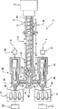
図1は、本発明による装置の断面図を示す。
好ましい態様の詳細な説明
本発明は、ポリエステル、最も詳しくはポリエチレンテレフタレート(PET)ポリエステルのような溶融ポリエステルからアセトアルデヒドを除去し、続いて直接射出成形して、低レベル(10ppm未満)のアセトアルデヒドを有する物品を形成する方法及び装置に関する。
本発明の実施に於いて、ジカルボン酸又はその低級アルキルジエステルのような二塩基酸とグリコールとを縮合させることによって製造することができるポリエステル組成物が製造される。中でも、ポリエステルを生成するのに使用することができるジカルボン酸及びその低級アルキルエステルは、テレフタル酸、イソフタル酸、フタル酸、ナフタレンジカルボン酸、コハク酸、セバシン酸、アジピン酸、アゼライン酸、ビ安息香酸、ヘキサヒドロフタル酸及びビス−p−カルボキシ−フェノキシエタンである。非常に有用なナフタレンジカルボン酸には、2,6−、1,4−、1,5−又は2,7−異性体が含まれるが、1,2−、1,3−、1,6−、1,7−、1,8−、2,3−、2,4−、2,5−及び/又は2,8−異性体も使用することができる。二塩基酸には、約2〜約40個の炭素原子が含有されていてよく、これにはイソフタル酸、アジピン酸、グルタル酸、アゼライン酸、セバシン酸、フマル酸、ダイマー酸、シス−又はトランス−1,4−シクロヘキサンジカルボン酸、ナフタレンジカルボン酸の種々の異性体等が含有される。好ましい二塩基酸には、テレフタル酸、イソフタル酸、ナフタレンジカルボン酸、シクロヘキサンジカルボン酸及びこれらの混合物が含まれる。二塩基酸は酸の形で、酸無水物の形で又は例えばジメチルエステルのようなそれらのエステルとして使用することができる。これらの酸及び/又はそれらの低級アルキルジエステルの1種又はそれ以上は、炭素数約3〜約10のグリコールを含有し、エチレングリコール、プロピレングリコール、1,3−プロパンジオール、1,4−ブタンジオール、1,6−ヘキサンジオール、ジエチレングリコール、1,4−シクロヘキサンジオール、1,4−シクロヘキサンジメタノール、ネオペンチルグリコール等を含む、1種又はそれ以上のグリコールと反応される。1,4−シクロヘキサンジメタノールは、シス形若しくはトランス形であってよく又はシス/トランス混合物としてであってもよい。好ましいグリコールには、エチレングリコール、1,4−シクロヘキサンジメタノール、ジエチレングリコール及びこれらの混合物が含まれる。1種又はそれ以上のジエステルは、1種又はそれ以上のグリコールと反応することができるので、本発明のポリエステルは、ホモポリエステルに限定されず、コポリエステル及び他のモノマーとのコポリマーのような混合ポリエステルも含む。
本発明の方法で特に有用であるポリエステルには、ポリ(エチレンテレフタレート)、ポリ(エチレンナフタレンジカルボキシレート)並びに約50モル%以下の変性二塩基酸及び/又はグリコールを含有するコポリエステルが含まれる。本発明の意図的のポリエステルの中で、少なくとも主量のポリエチレンテレフタレートを含有するものが好ましく、200モル%基準で少なくとも80モル%のテレフタル酸及び80モル%のエチレングリコールを含有するものが最も好ましい。ポリエチレンテレフタレートは、それ自体二つの異なった方法の一つによって中間体として生成されるビス−(2−ヒドロキシエチル)テレフタレートの重合によって生成されたポリエステルから生成される。ビス−(2−ヒドロキシエチル)テレフタレートを製造する一つの方法は、米国特許第3,050,533号に記載されているような、テレフタル酸とエチレングリコールとの直接エステル化によるものである。この方法に於いて、反応の副生物は水であり、これは反応生成物から蒸留される。ビス−(2−ヒドロキシエチル)テレフタレートを製造する第二の方法は、テレフタル酸のジアルキルエステル、好ましくはテレフタル酸ジメチルとエチレングリコールとのエステル交換反応によるものである。好ましくは、エチレングリコールの2モル比率が、テレフタル酸ジアルキルの1モル比率と反応する。更に好ましくは、テレフタル酸ジアルキルの1モル比率当たり、エチレングリコールの2モル比率より多くが使用される。それは、これらの条件下で、初期エステル交換反応が、より迅速に且つ完全に起こるからである。このエステル交換反応は、上昇した温度の条件下で行われる。例えば、ほぼ反応混合物の沸騰温度から250℃のように高いまでの範囲内の温度を使用することができる。この反応は、大気圧、大気圧より低い又は大気圧より高い圧力で起こり得る。エステル交換反応の副生物はアルカノールである。例えば、テレフタル酸ジメチルが使用される場合、メタノールが生成する。次いで、アルカノールは反応混合物から除去される。
反応速度を上昇させるために、エステル交換反応において公知の多くの触媒を使用することができる。使用することができる典型的ポリエステル化触媒には、チタンアルコキシド、ジブチルスズジラウレート並びに別々に若しくは任意に亜鉛、マンガン若しくはマグネシウムの酢酸塩若しくは安息香酸塩と組み合わせて使用される酸化アンチモン若しくは三酢酸アンチモン並びに/又は当業者に公知であるような他の触媒物質が含まれる。リン及びコバルト化合物が任意に、反応の開始時から存在していてよく又はこれらを工程の全ての便利な点で添加することができる。
中間体ビス−(2−ヒドロキシエチル)テレフタレートを製造した後、グリコール又は水の除去を実施する条件下で、エチレングリコール又は反応混合物の沸点よりも高い温度で加熱することによって、これをポリエチレンテレフタレートに転化することができる。この加熱は、所望により325℃のように高い温度で起こってもよい。加熱の間に、過剰のグリコール及び水の迅速な蒸留を行わせるように、圧力を低下させる。最終ポリエチレンテレフタレートポリエステルは、オルトクロロフェノール中で25℃で測定したとき、0.3dL/gを越える極限粘度を有するであろう。更に好ましくは、このポリエステルの極限粘度(intrinsic viscosity)は、オルトクロロフェノール中で25℃で測定したとき、約0.4〜約1.0dL/gの範囲である。更に好ましくは、本発明で使用されるポリエチレンテレフタレートは、オルトクロロフェノール中で25℃で測定したとき、約0.5〜約0.7dL/gの極限粘度を有する。本発明の熱可塑性ポリエステル含有ポリエステルは、約200℃〜約330℃、更に好ましくは、約220℃〜約290℃、最も好ましくは約250℃〜約275℃の範囲内の好ましい融点を有する。
アクリル酸及びメタクリル酸並びに芳香族及び脂肪族ポリオールのエーテル、エステル及び部分エステルのような成分が、ポリエステルコポリマー中のコモノマーとして使用するのに適している。このようなコポリマーの製造は、当該技術分野で公知である。
最終物品の所望の特性の性質に依存して、多数の異なった種類の添加物を使用することができる。このような添加物には、これらに限定されないが、着色剤、酸化防止剤、アセトアルデヒド低減剤、安定剤、例えば、UV及び熱安定剤、衝撃改良剤、重合触媒失活剤、溶融物強度増強剤、連鎖延長剤、帯電防止剤、滑剤、核生成剤、溶媒、充填材、可塑剤等が含まれる。
図1は、本発明により典型的な装置を示す。これは、脱蔵(devolatilizing)押出機2及び複数個の成型装置4及び6からなっている。装置の脱蔵押出機部分は、当該技術分野で公知であるような単軸スクリュー又は二軸スクリュー型のものである。ポリエステル前駆体、好ましくはPET前駆体は、上流で連続的に反応し、ポリエステル溶融物を生成する。上流処理装置、典型的に重縮合反応器からの溶融PETポリエステルは、入口ノズル8で装置の脱蔵押出機部分2のバレル10に入る。バレル10の内側には、駆動トレイン(train)又はモーター14により固定速度で回転される1個又はそれ以上のスクリュー12がある。押出機2は、後で更に完全に説明されるような一連のセクション又はゾーンを有する。このゾーンは、スクリューの外径に加えてスクリュー12の谷径又はバレル10の内径を変化させることによるようにして、ポリエステルに加えられる異なった圧力を有するとして特徴付けられる。
ポリエステルは、押出機の第一ゾーン16に配置された入口ノズル8で押出機の中に入る。ポリエステルの温度は、ポリエステルの融点よりも高く、好ましくはポリエステルの融点よりも約10〜約20℃以下を超えない程度高い。溶融ポリエステルは、押出機、ギャーポンプ又は粘稠な液体を輸送するための他の適当なポンプ輸送装置を使用して、ノズル8にポンプ輸送することができる。溶融物は任意に、平行な装置へ供給する分布システム及び任意のポリエステルフィルターを通過することができる。ポリエステルのインヘレント粘度(IhV)は一般的に約0.5〜約1.0の範囲内である。好ましいIhV範囲は、約0.7〜約0.9である。本明細書で使用するとき、用語「IhV」は、フェノール(60体積%)とテトラクロロエタン(40体積%)との混合物100mL中に溶解させた0.5gのポリエステルの溶液によって決定した、ポリエステルのインヘレント粘度を指す。ノズル8への供給ラインは、滞留時間を最小にし(好ましくは5分未満)、過度の熱い壁温度無しに、所望の温度を維持し、ポリエステルが蓄積し及び分解し得る全てのデットポケットを排除し、そして最小の剪断の条件下でポリエステルを輸送するようなものでなくてはならない。ポリエステルは、セクション16で、不活性である、即ちポリエステルと反応性でないガスと混合される。ガスは、ノズル18の手段によってゾーン16の中に注入され、ガスとポリエステルとはこのゾーン16内で、約1000〜約3000psigの圧力下に混合される。本発明の状況内で有用なガスには、非排他的に、窒素、二酸化炭素、C1〜C4炭化水素、除湿した空気、貴ガス及びこれらの混合物が含まれる。ガスは、後の除去のために、ポリエステル溶融物中に存在するアセトアルデヒドを溶解するのに十分な量で存在している。不活性ガス流量は、典型的に約1.0SCF/ポリエステルポンド以下であり、約0.25SCF/ポンド以下の流量が好ましい。ガス注入ノズルは、僅かな大きい泡ではなくて、多数の小さい泡が形成されるように設計しなくてはならない。ガスを分散させる目的のための注入ノズルの設計は、当該技術分野で公知である。このゾーン内のスクリューは、これらの泡のより以上の破壊及び溶融ポリエステル中への分散を起こすように設計しなくてはならない。
次いでポリエステルとガスとの混合物は、溶融ポリエステルが、ゾーン16内の高圧、即ち、約1000〜3000psigの領域から、脱泡ゾーン22での10mmHg未満、好ましくは1mmHg未満の低圧の領域へ移行する、圧力低下ゾーン20を通って移動する。圧力低下ゾーン20で、ポリエステルの流れは、これらに限定されていが、可変流れ面積型バレル弁配置、逆ポンプ輸送スクリューねじ又は固定流れ制限ブリスターリング配置を含む公知の手段によって制限される。これらの流れ制限方法の適用及び使用は、押出機設計の技術分野に於いて公知である。
圧力低下によって、部分的に充填され、そしてガス抜きされた脱泡セクション22に於いて減圧の条件下に溶融物フォームが作られる。ゾーン22に於いて、バレル壁とスクリュー(群)とによって結合された開放領域は、スクリューねじの深さ又はバレル/スクリュー直径を増加させることを組み合わせることによって顕著に拡大される。このゾーンには、真空ポンプに取り付けられたベントノズル24が設けられ、このゾーン内の圧力を、10mmHg未満、好ましくは1mmHg未満の圧力に維持することができるようになっている。溶融ポリエステルが制限ゾーン20を通過するとき、気泡が膨張して、低密度発泡ポリエステル/ガス相を作る。ゾーン22内の開放領域は、フォームが、バレル壁とスクリュー(群)とによって結合された空の体積を完全に充填しないようにしなくてはならない。典型的に、フォームによって占められた空の体積の部分は、50〜70%を越えてはならない。形成されると、このフォームは、典型的に約1分以下であるゾーン22内の滞留時間でバレルを下方に輸送され、溶解したアセトアルデヒドを、溶融ポリエステル相から出たガス相の中へ拡散させるために適当な時間を与える。
圧縮ゾーン26は残留する全ての気泡を実質的に追い出して、全ての気泡が存しない連続溶融物相を生成する。発泡したポリエステルが減少した開放領域のこのゾーン26を通過するとき、発泡したポリエステルは最初に、バレル壁とスクリュー(群)とによって結合された空の体積を充填し、次いで空の体積が次第に小さくなるので、気泡は溶融ポリエステルから押し出される。このゾーンの終わりで、溶融相ポリエステルは、スクリュー(群)とバレル壁とによって結合された空の体積を実質的に完全に充填し、実質的に如何なる気泡も有しない。
脱蔵されたアセトアルデヒドを含有する不活性ガスは、バレル10からノズル24を通ってガス抜きされる。発泡溶融物を有効に輸送し、バレルの部分充填の条件下でガス抜きするスクリューの設計は、押出機設計の技術分野で公知である。ゾーン26の下流にはゾーン28があり、ここではバレル開放領域は本質的に一定であり、溶融ポリエステルはポンプ32の吸込みの方に輸送される。このゾーン28内の圧力は、回転スクリューのポンプ輸送作用のために約200〜400psigまで幾らか上昇する。このゾーンにはまた、それを通してアセトアルデヒド低減剤を添加することができるノズル30が設けられている。溶融物へのアセトアルデヒド低減剤の添加及び混合は、ガス抜きスクリューセクション22に対して下流で生成された全てのアセトアルデヒドを捕捉する機能を果たす。このアセトアルデヒド低減剤は、典型的に、供給ギャーポンプを使用して溶融樹脂中に計量される。添加の割合は典型的に、添加剤0.5ポンド/ポリエステル処理量100ポンド未満の比である。アセトアルデヒド低減剤の量は、ガス抜き脱蔵セクション22に対して下流で生成したアセトアルデヒドを捕捉するために必要な量のみが供給されるように、最小にすべきである。適当なアセトアルデヒド低減剤には、これらに限定されないが、米国特許第5,266,413号、同第5,258,233号及び同第4,837,115号に開示されているもののようなポリアミド、特願昭62−182065号(1987年)に開示されているもののようなポリエステルアミド、ナイロン6及びその他の脂肪族ポリアミド、米国特許第4,357,461号に開示されているようなエチレンジアミン四酢酸、米国特許第5,250,333号に開示されているようなアルコキシル化ポリオール、米国特許第4,330,661号に開示されているようなビス(4−β−ヒドロキシエトキシフェニル)スルホン、米国特許第5,l04,965号に開示されているようなゼオライト化合物、米国特許第4,093,593号に開示されているような5−ヒドロキシイソフタル酸、米国特許第4,403,090号に開示されているようなポリ(エチレンイソフタレート)、米国特許第5,049,647号及び米国特許第4,764,323号に開示されているような超臨界二酸化炭素及び米国特許第4,447,595号及び米国特許第4,424,337号に開示されているようなプロトン酸触媒が含まれる。好ましいアセトアルデヒド低減剤には、ポリエステルアミド及び脂肪族ポリエステルアミドが含まれる。スクリューセクション28は、添加物をポリエステルと十分に混合するように設計しなくてはならない。このセクション28での滞留時間は典型的に、約20秒以下でなくてはならない。溶融添加物中で混合するスクリューの設計は、押出機設計の技術分野で公知である。スクリューは過剰の剪断を最小にするように設計しなくてはならず、バレル加熱配置及び制御は、過度の壁温度を最小にし、均一な加熱を与えるように設計しなくてはならない。押出機内の全滞留時間は、合計で約2分を越えてはならない。
好ましくは回転ギャーポンプであるポンプ32は、ゾーン28の終端に配置されている。ギャーポンプ32の目的は、流れチャンネル34を通って、一般的に4及び6によって示されるもののような1個又はそれ以上の成型装置に至るようにポリエステルを賦勢するための適当な圧力を与えることである。ギャーポンプの吐出部での典型的な圧力は、約1000〜3000psigの範囲内にしなくてはならない。脱蔵押出機スクリューの終端でスクリューポンプ輸送ゾーンの代わりにギャーポンプを使用することによって、ポリエステルの短縮された滞留時間及びより小さい剪断加熱の利点が与えられる。また、ポンプ輸送速度は、通常、一定速度で運転し、良好な発泡及び高いアセトアルデヒド脱蔵効果を維持するために設定すべきであるスクリュー速度を変更させることなく、均一に維持することができる。
ギャーポンプ32を出たポリエステルは、チャンネル34を通って、締切弁36及び37を経て流れ、溶融物を連続的にポンプ輸送して、成型装置4及び6の2個のアキュームレータリザーバー38を交互に充填し、そうしてインジェクター42によりその付属する金型40の中に射出するための1回分の材料を充填し、蓄積する。ギャーポンプ32からのフローチャンネル34はポリエステルをアキュームレータリザーバー38の中に排出し、ポリエステルの滞留時間が最小、好ましくは約30秒以下であるようにする。これらのチャンネル34は好ましくは均一に加熱され、ポリエステル溶融温度を約20℃より高く超えない温度で維持され、ポリエステルが蓄積及び分解する「デッド」ポケットが存在しないように設計される。開口46での排出を伴うパージ弁44を含めることが、始動、運転停止及び工程間アップセットのために望ましい。
成型装置6のリザーバー38の充填の間に、締切弁36が開かれ、成型装置4に付随する締切弁37が閉じられる。また、金型への締切弁48が閉じられる。充填の間、ラムピストン42が、ギャーポンプによって発生された圧力のために引っ込み、従ってリザーバー38を膨張させる。フルショットがリザーバー38内に蓄積されると、成型装置6への締切弁36が閉じ、成型装置4に付随する締切弁37が開き、そうして、成型装置4のリザーバー38の充填を開始するために、ポリエステル流れを向ける。締切弁36が閉じると、装置6の金型への締切弁48が開き、射出ラム42が、油圧射出装置50からの油圧の下で前方に動いて、溶融ポリエステルを金型40の中に射出する。弁48は、ショット時間の間、典型的に約10秒以内ラムが前方位置にあって開いたままであり、金型内でのポリエステルの冷却及び固化を可能にする。この時間が経過した後、弁48が閉じる。典型的に約5〜約15秒間である追加の金型冷却時間が経過した後、装置6の金型は型締機構52によって開かれ、成型された部品が取り出され、金型が閉じ、金型を閉止位置に保持するように油圧が適用される。成型装置6での射出、金型冷却及び部品取り出しの間、成型装置4でリザーバー38の充填及びラムピストン42の引き込みが起こる。成型装置4でフルショットが蓄積されると、締切弁37が閉じ、締切弁36が再び開く。射出、金型冷却及び部品取り出しが、成型装置6について説明したようにして成型装置4で起こり、一方、成型装置6についてリザーバーの再充填が起こる。成型機に付属する中央コントローラーが、上記の全ての工程を一定の順序で配列する。金型、油圧クランプ及び射出ラムの設計及び運転についての詳細は、成型機設計の技術分野で公知である。
本装置は、一つのコンパクトな装置内で、典型的に最終重合反応器から排出される溶融ポリエステルの連続流を受け取り、不活性ガス発泡及び分離を使用してアセトアルデヒドを低レベルまで有効に除去し、全ての残留アセトアルデヒドを有効に捕捉し、そして迅速に造形物品を成型する能力を提供する。最終成型物品中のアセトアルデヒドの濃度は、典型的に5ppmより少なく、好ましくは3ppmより少ないであろう。Background of the Invention
Technical field
The present invention relates to an apparatus and method for producing molded polyester articles. More particularly, the present invention relates to an apparatus and method for continuously producing molded polyester articles having a low acetaldehyde content from a melt produced by continuously reacting a polyester precursor. The polyester is manufactured and formed into a shaped article useful in a single integrated continuous melt molding process without intermediate solidification of the melt.
Description of prior art
It is well known that polyester is widely used in the manufacture of molded articles such as food and beverage containers. thispolyesterIs generally produced by a batch or continuous melt phase polycondensation reaction, as is known in the art. Then thispolyesterIs pelletized and used in various extrusion or molding operations. During the production and processing of polyester in the melt phase, certain by-products are produced. One such byproduct is acetaldehyde, and its presence in molded food containers, beverage bottles, water bottles, etc. is very harmful. It is highly desirable to produce a preform having less than about 10 ppm acetaldehyde, particularly for taste sensitive beverages such as cola, beer and water. Acetaldehyde is a polyethylene terephthalate (PET) and similarpolyesterThis low level of acetaldehyde is difficult to achieve because it is continuously produced as a by-product during the polymerization and subsequent melt processing.
In the prior art, various attempts have been made to reduce the acetaldehyde content of molded polyester articles. Three-stage processes have been commonly used to provide polyester polymers suitable for use in applications where it is important to minimize the presence of acetaldehyde. Such methods typically include relatively low molecular weight precursors by melt phase polymerization techniques known in the art.polyesterThe manufacture of is included. The acetaldehyde content of such precursors ranges from about 30 ppm to over 150 ppm, depending on the reaction conditions selected. The precursor is then cooled, formed into pellets, crystallized and subjected to further solid state polymerization at low temperature. Typically, an inert gas is used to separate glycols, acetaldehyde and other reaction by-products from the pellet so that the acetaldehyde content is reduced to about 1 ppm or less at the end of the solid phase process. The product thus produced must be further heated and melted in a third step in order to form a useful shape such as a beverage bottle preform (preform), This process typically causes an increase in acetaldehyde content from less than 1 ppm in the pellets to about 5 to about 10 ppm or more in the shaped article. This dramatic increase in acetaldehyde occurs despite the fact that the molding process typically takes 1 or 2 minutes to complete.
US Pat. No. 5,597,891 reduces the acetaldehyde content of molten PET to a level suitable for direct use in food packaging articles by contacting it with molten polyester using an inert (purge) gas. An improved method for the is described. U.S. Pat. No. 4,734,243 describes an injection molding machine for plastics provided with a plasticizing device which continuously plasticizes the material and supplies a plurality of injection devices in the usual order. German Patent DE 19 505 680 describes a process for producing bottle preforms from melts by introducing an inert gas into a continuous stream of polyester melt and reducing the acetaldehyde content to less than 10 ppm. . German patent application DE 195 030 53 describes the direct production of molded containers which use common catalysts and do not taste from thermoplastic polyesters. The inert gas is dispersed in the polyester melt immediately after leaving the reactor and vacuum degassed just before the molder. This inert gas is dispersed by means of a fixed pipeline mixer, and defoaming takes place in a flash vessel under vacuum with an enlarged pipe section or optional stirrer. A polyamide type acetaldehyde reducing agent is added in the vicinity of the inert gas supply point. In Japanese Patent Application No. 5-315154, water injection, dispersion, bubbling and defoamingpolyesterA method and apparatus for evaporating and removing volatiles present therein is described. US Pat. No. 5,080,845 melts supercritical extraction gas under pressure in an extruderpolyesterAnd then the mixture is transferred to a second extruder operated under reduced pressure and the gas is vented with the extruded impurities and substantially free of impurities.polyesterBy discharging material,polyesterA method for removing low molecular weight substances from a material is described. U.S. Pat.No. 5,459,168 describes an impure thermoplastic using an extrusion device.polyesterIs described to remove low molecular weight compounds. This extrusion apparatus has a heated housing, in which a first low pressure zone, a high pressure zone (here the separating agent is melted).polyester), The extraction zone (where some of the separating agent and low molecular weight compounds are removed), the second low pressure zone (here, the low molecular weight compounds and the remainder of the separating agent are removed), final High pressure zone as well as extruder head (purified throughpolyesterIs recovered). U.S. Pat. No. 5,597,525 describes a method of injection molding polyethylene terephthalate by using a vented injection device as a means for omitting pre-drying of the resin. This device does not cause inferior screw biting, and even when the molding material is undried, uncrystallized or crystallized PET, it can be used to produce molded products such as preforms to produce thin-walled containers. A certain amount of material can be supplied at any time for injection molding. This patent includes melting to minimize the production of additional AApolyesterIt is stated that it is necessary to keep the temperature at a minimum.
Thereby, PET and similarpolyesterPolyesters such as are continuously produced in the molten state, from which excess acetaldehyde and other by-products are removed, and directly from the melt into useful shaped articles such as beverage bottle preforms with low acetaldehyde content. It has been found that the apparatus and method can be used to transfer to a molding apparatus. The apparatus of the present invention not only avoids costly additional conventional processing steps such as cooling, shredding, drying, crystallization, solid state polymerization and remelting, but the shaped article produced is even lower. Acetaldehyde content, better color,polyesterEliminates the lowering of molecular weight attributed to degradation and defects known as “bubbles” and “non-melt” that are sometimes formed during conventional molding processes.
Summary of invention
The present invention
A) a) a cylindrical barrel having a plurality of consecutively connected zones along the inside of the barrel, at least one screw shaft along the inside of the barrel passing through the zone, and means for rotating the shaft ;
b) about 1000 to about 3000 psig(71.34-211.95kgf / cm 2 )Molten thermoplastic under pressure ofpolyesterThermoplastics in the first mixing zone of the barrel with means for mixing the gas and the gas thereby producing a mixturepolyesterInlet and gas injection port;
c) means for causing the flow of the mixture through the pressure drop zone to the defoaming zone;
d) can be maintained at a lower pressure than the atmosphere, andpolyesterHas a vacuum gas vent that can remove gas from and degassedpolyesterA defoaming zone for feeding the second mixing zone
e) has an inlet port;polyesterA second mixing zone that can be mixed and fed to the outlet of the barrel;
f)polyesterPumping means at the outlet of the barrel to pump the mold to the molding equipment
An extruder consisting of
B) Melting from pumping meanspolyesterReceive this continuouslypolyesterPumping means for forming molded articles frompolyesterAt least one molding device in flow communication
ComprisingpolyesterAn apparatus for manufacturing a molded article is provided.
The present invention also provides
a)The molten polyester stream is about 1000 to about 3000 psig with a gas stream that is substantially inert to the polyester.(71.34-211.95kgf / cm 2 )Forming a mixture by mixing under the pressure of
b)Foaming the mixture by reducing the pressure of the mixture to below atmospheric pressure, and then separating the gas in the mixture from the polyester by means of vacuum,
c)Blending the defoamed polyester with an acetaldehyde reducing agent to form a blend;
d)Form a solid molded article from this blend without solidifying the polyester before forming the solid molded article
A method for continuously producing a molded polyester article is provided.
The present invention also provides
A)a) a plurality of continuously connected zones along the inside of the barrel, at least one screw shaft along the inside of the barrel passing through the zone, and a cylindrical barrel having means for rotating the shaft ;
b) about 1000 to about 3000 psig(71.34-211.95kgf / cm 2 )Molten thermoplastic under pressure ofpolyesterThermoplasticity in the first mixing zone of the barrel with means to produce a mixture by mixing the gas with gaspolyesterInlet and gas injection port;
c) means for causing the flow of the mixture through the pressure drop zone to the defoaming zone;
d) can be maintained at a lower pressure than the atmosphere, andpolyesterHas a vacuum gas vent that can remove gas from and degassedpolyesterA defoaming zone for feeding the second mixing zone
e) has an inlet port;polyesterA second mixing zone that can be mixed and fed to the outlet of the barrel;
f)polyesterPumping means at the outlet of the barrel for pumping the mold to the molding machine
Providing an extruder comprising:
B)A stream of molten polyester is continuously flowed into the first mixing zone of the extruder without allowing the polyester to solidify prior to entering the extruder, and the stream of molten polyester is substantially directed against the polyester. About 1000 to about 3000 psig by mixing with an injected stream of gas that is inert(71.34-211.95kgf / cm 2 )Forming a mixture under the pressure of
C)Flowing this mixture through the pressure drop zone to the defoaming zone;
D)This mixture is defoamed in a defoaming zone maintained at a pressure below atmospheric pressure, and by means of a vacuum gas vent.polyesterRemoving gas from the
E)DefoamedpolyesterIn a second mixing zone with an acetaldehyde reducing agent,
F)thispolyesterTransport this to the barrel outletpolyesterPumping from barrel to molding equipment, and
G)thispolyesterContinuously forming molded articles from
A method for continuously producing a molded polyester article is provided.
[Brief description of the drawings]
FIG. 1 shows a cross-sectional view of a device according to the invention.
Detailed Description of the Preferred Embodiment
The present invention relates to polyester, most particularly polyethylene terephthalate (PET).polyesterLike meltingpolyesterThe present invention relates to a method and apparatus for removing acetaldehyde from and subsequently direct injection molding to form articles having low levels (less than 10 ppm) of acetaldehyde.
In the practice of the present invention, a polyester composition is produced that can be produced by condensing a dibasic acid, such as a dicarboxylic acid or its lower alkyl diester, with a glycol. Among them, dicarboxylic acids and lower alkyl esters thereof that can be used to produce polyesters are terephthalic acid, isophthalic acid, phthalic acid, naphthalenedicarboxylic acid, succinic acid, sebacic acid, adipic acid, azelaic acid, bibenzoic acid. Hexahydrophthalic acid and bis-p-carboxy-phenoxyethane. Very useful naphthalenedicarboxylic acids include the 2,6-, 1,4-, 1,5- or 2,7-isomer, but the 1,2-, 1,3-, 1,6-isomers. 1,7-, 1,8-, 2,3-, 2,4-, 2,5- and / or 2,8-isomers can also be used. The dibasic acid may contain from about 2 to about 40 carbon atoms, including isophthalic acid, adipic acid, glutaric acid, azelaic acid, sebacic acid, fumaric acid, dimer acid, cis- or trans Various isomers of -1,4-cyclohexanedicarboxylic acid and naphthalenedicarboxylic acid are contained. Preferred dibasic acids include terephthalic acid, isophthalic acid, naphthalenedicarboxylic acid, cyclohexanedicarboxylic acid and mixtures thereof. The dibasic acids can be used in the acid form, in the acid anhydride form or as their esters, for example dimethyl esters. One or more of these acids and / or their lower alkyl diesters contains a glycol having from about 3 to about 10 carbon atoms, and includes ethylene glycol, propylene glycol, 1,3-propanediol, 1,4-butane. Reacted with one or more glycols including diol, 1,6-hexanediol, diethylene glycol, 1,4-cyclohexanediol, 1,4-cyclohexanedimethanol, neopentyl glycol and the like. 1,4-cyclohexanedimethanol may be in the cis or trans form or as a cis / trans mixture. Preferred glycols include ethylene glycol, 1,4-cyclohexanedimethanol, diethylene glycol and mixtures thereof. Since one or more diesters can react with one or more glycols, the polyesters of the invention are not limited to homopolyesters, but are mixed like copolymers with copolyesters and other monomers. Also includes polyester.
Particularly useful in the method of the present inventionpolyesterIncludes poly (ethylene terephthalate), poly (ethylene naphthalene dicarboxylate) and copolyesters containing up to about 50 mol% of modified dibasic acids and / or glycols. Of the intended polyesters of the present invention, those containing at least a major amount of polyethylene terephthalate are preferred, and those containing at least 80 mole percent terephthalic acid and 80 mole percent ethylene glycol based on 200 mole percent are most preferred. . Polyethylene terephthalate was produced by polymerization of bis- (2-hydroxyethyl) terephthalate, itself produced as an intermediate by one of two different methods.polyesterGenerated from One method of producing bis- (2-hydroxyethyl) terephthalate is by direct esterification of terephthalic acid and ethylene glycol, as described in US Pat. No. 3,050,533. In this process, the byproduct of the reaction is water, which is distilled from the reaction product. A second method for producing bis- (2-hydroxyethyl) terephthalate is by a transesterification reaction of a dialkyl ester of terephthalic acid, preferably dimethyl terephthalate and ethylene glycol. Preferably, a 2 molar ratio of ethylene glycol reacts with a 1 molar ratio of dialkyl terephthalate. More preferably, more than 2 mole ratio of ethylene glycol per mole ratio of dialkyl terephthalate is used. This is because the initial transesterification reaction occurs more rapidly and completely under these conditions. This transesterification reaction is carried out under elevated temperature conditions. For example, temperatures in the range of approximately from the boiling temperature of the reaction mixture to as high as 250 ° C. can be used. This reaction can occur at atmospheric pressure, below atmospheric pressure or above atmospheric pressure. A by-product of the transesterification reaction is an alkanol. For example, when dimethyl terephthalate is used, methanol is produced. The alkanol is then removed from the reaction mixture.
Many catalysts known in the transesterification can be used to increase the reaction rate. Typical polyesterification catalysts that can be used include titanium alkoxide, dibutyltin dilaurate and antimony oxide or antimony triacetate used separately or optionally in combination with zinc, manganese or magnesium acetate or benzoate and / or Or other catalytic materials as known to those skilled in the art. Phosphorus and cobalt compounds can optionally be present from the beginning of the reaction or they can be added at all convenient points in the process.
After producing the intermediate bis- (2-hydroxyethyl) terephthalate, it is converted to polyethylene terephthalate by heating at a temperature above the boiling point of ethylene glycol or the reaction mixture under conditions that effect the removal of glycol or water. Can be converted. This heating may occur at a high temperature, such as 325 ° C., if desired. During heating, the pressure is reduced to allow rapid distillation of excess glycol and water. Final polyethylene terephthalatepolyesterWill have an intrinsic viscosity in excess of 0.3 dL / g when measured at 25 ° C. in orthochlorophenol. More preferably, thispolyesterThe intrinsic viscosity of the resin ranges from about 0.4 to about 1.0 dL / g when measured at 25 ° C. in orthochlorophenol. More preferably, the polyethylene terephthalate used in the present invention has an intrinsic viscosity of about 0.5 to about 0.7 dL / g when measured in orthochlorophenol at 25 ° C. Contains thermoplastic polyester of the present inventionpolyesterHas a preferred melting point within the range of about 200 ° C to about 330 ° C, more preferably about 220 ° C to about 290 ° C, and most preferably about 250 ° C to about 275 ° C.
Components such as acrylic and methacrylic acid and ethers, esters and partial esters of aromatic and aliphatic polyols are suitable for use as comonomers in the polyester copolymer. The production of such copolymers is known in the art.
Many different types of additives can be used, depending on the nature of the desired properties of the final article. Such additives include, but are not limited to, colorants, antioxidants, acetaldehyde reducers, stabilizers such as UV and thermal stabilizers, impact modifiers, polymerization catalyst quenchers, melt strength enhancements. Agents, chain extenders, antistatic agents, lubricants, nucleating agents, solvents, fillers, plasticizers and the like.
FIG. 1 shows a typical apparatus according to the present invention. This consists of a
polyesterEnters the extruder at an inlet nozzle 8 located in the
ThenpolyesterAnd gas mixture meltspolyesterTravels through the pressure drop zone 20, which transitions from the high pressure in
The pressure drop creates a melt foam under conditions of reduced pressure in the partially filled and degassed
The
The inert gas containing devolatilized acetaldehyde is vented from the
A
Exited the gear pump 32polyesterFlows through the
During the filling of the
The apparatus receives a continuous stream of molten polyester, typically discharged from the final polymerization reactor, in one compact apparatus, and effectively removes acetaldehyde to low levels using inert gas foaming and separation. , Effectively capture all residual acetaldehyde and provide the ability to rapidly shape shaped articles. The concentration of acetaldehyde in the final molded article will typically be less than 5 ppm, preferably less than 3 ppm.
Claims (21)
b)1000〜3000psig(71.34〜211.95kgf/cm 2 )の圧力下で、溶融熱可塑性ポリエステルとガスとを混合することによって混合物を生成する手段を有する、バレルの第一混合ゾーンにおける溶融熱可塑性ポリエステル入口及びガス注入ポート;
c)圧力低下ゾーンを通って脱泡ゾーンまでの混合物の流れを起こさせる手段;
d)大気より低い圧力に維持することができ、そしてポリエステルからのガスを除去することができる真空ガスベントを有し、脱泡したポリエステルを第二混合ゾーンに送る脱泡ゾーン;
e)入口ポートを有し、ポリエステルを混合し、バレルの出口まで送ることができる、第二混合ゾーン;
f)ポリエステルを成型装置にポンプ輸送する、バレルの出口におけるポンプ輸送手段
を含んでなる押出機、並びに
B)ポンプ輸送手段から溶融ポリエステルを連続的に受け取り、このポリエステルから成型物品を形成させる、ポンプ輸送手段とポリエステル流れ連通状態にある少なくとも1個の成型装置
からなるポリエステル成型物品の製造装置。A) a) a cylindrical barrel having a plurality of consecutively connected zones along the inside of the barrel, at least one screw shaft along the inside of the barrel passing through the zone, and means for rotating the shaft ;
b) 1000~3000psig (under a pressure of 71.34~211.95kgf / cm 2), comprising means for creating a mixture by mixing a molten thermoplastic polyester and a gas, the molten thermoplastic polyester in the first mixing zone of the barrel Inlet and gas injection port;
c) means for causing the flow of the mixture through the pressure drop zone to the defoaming zone;
d) can be maintained at a subatmospheric pressure, and has a vacuum gas vent capable of removing gas from polyester, defoaming zone Send defoamed polyester to a second mixing zone;
e) a second mixing zone having an inlet port, where the polyester can be mixed and sent to the outlet of the barrel;
f) an extruder comprising pumping means at the outlet of the barrel for pumping the polyester to a molding device, and B) a pump for continuously receiving molten polyester from the pumping means and forming a molded article from the polyester. An apparatus for producing a polyester molded article comprising at least one molding apparatus in communication with a transport means and a polyester flow.
b)この混合物の圧力を大気圧より低い圧力まで低下させ、それによってこの混合物を発泡させ、その後、真空の手段によって混合物中のガスをポリエステルから分離すること、
c)脱泡したポリエステルをアセトアルデヒド低減剤とブレンドして、ブレンドを形成させること、
d)固体成型物品を形成させる前にポリエステルを固化させることなく、このブレンドから固体成型物品を形成させる
ことを含んでなる、成型ポリエステル物品の連続製造方法。 a) The molten polyester stream is mixed with a gas stream that is substantially inert to the polyester under a pressure of 1000 to 3000 psig (71.34 to 211.95 kgf / cm 2 ) , thereby forming a mixture. thing,
b) reducing the pressure of the mixture to a pressure below atmospheric pressure, thereby foaming the mixture and then separating the gas in the mixture from the polyester by means of vacuum;
c) blending the defoamed polyester with an acetaldehyde reducing agent to form a blend;
d) A continuous process for producing a molded polyester article comprising forming a solid molded article from this blend without solidifying the polyester prior to forming the solid molded article.
b)1000〜3000psig(71.34〜211.95kgf/cm 2 )の圧力下で、溶融熱可塑性ポリエステルとガスとを混合することによって混合物を生成する手段を有する、バレルの第一混合ゾーンにおける溶融熱可塑性ポリエステル入口及びガス注入ポート;
c)圧力低下ゾーンを通って脱泡ゾーンまでの混合物の流れを起こさせる手段;
d)大気より低い圧力に維持することができ、そしてポリエステルからのガスを除去することができる真空ガスベントを有し、脱泡したポリエステルを第二混合ゾーンに送る脱泡ゾーン;
e)入口ポートを有し、ポリエステルを混合し、バレルの出口まで送ることができる、第二混合ゾーン;
f)ポリエステルを成型装置にポンプ輸送する、バレルの出口におけるポンプ輸送手段
からなる押出機を用意すること、
B)溶融ポリエステルの流れを、押出機の中に入れる前にポリエステルを固化させることなく、押出機の第一混合ゾーンの中に連続的に流し、溶融ポリエステルの流れを、このポリエステルに対して実質的に不活性であるガスの注入された流れと混合することによって1000〜3000psig(71.34〜211.95kgf/cm 2 )の圧力下で混合物を形成させること、
C)この混合物を圧力低下ゾーンを通して、脱泡ゾーンまで流すこと、
D)この混合物を大気圧より低い圧力に維持された脱泡ゾーン内で脱泡し、真空ガスベント手段によってポリエステルからガスを除去すること、
E)脱泡したポリエステルを、第二混合ゾーン内でアセトアルデヒド低減剤と混合すること、
F)このポリエステルをバレルの出口まで輸送し、このポリエステルをバレルから成型装置までポンプ輸送すること、並びに
G)このポリエステルから成型物品を連続的に形成させる
ことを含んでなる、成型ポリエステル物品の連続製造方法。 A) a) Cylindrical barrel having a plurality of consecutively connected zones along the inside of the barrel, at least one screw shaft along the inside of the barrel passing through the zone, and means for rotating the shaft ;
b) 1000~3000psig (under a pressure of 71.34~211.95kgf / cm 2), comprising means for creating a mixture by mixing a molten thermoplastic polyester and a gas, the molten thermoplastic polyester in the first mixing zone of the barrel Inlet and gas injection port;
c) means for causing the flow of the mixture through the pressure drop zone to the defoaming zone;
d) can be maintained at a subatmospheric pressure, and has a vacuum gas vent capable of removing gas from polyester, defoaming zone Send defoamed polyester to a second mixing zone;
e) a second mixing zone having an inlet port, where the polyester can be mixed and sent to the outlet of the barrel;
f) preparing an extruder comprising pumping means at the outlet of the barrel for pumping the polyester to a molding device;
B) A stream of molten polyester is continuously flowed into the first mixing zone of the extruder without allowing the polyester to solidify prior to entering the extruder, and the stream of molten polyester is substantially directed against this polyester. Forming a mixture under a pressure of 1000 to 3000 psig (71.34 to 211.95 kgf / cm 2 ) by mixing with an injected stream of gas that is inert
C) flowing the mixture through the pressure drop zone to the defoaming zone;
D) defoaming this mixture in a defoaming zone maintained at a pressure below atmospheric pressure and removing gas from the polyester by means of a vacuum gas vent;
E) mixing the defoamed polyester with an acetaldehyde reducing agent in the second mixing zone;
F) transporting the polyester to the outlet of the barrel, pumping the polyester from the barrel to the molding machine, and
G) comprising a possible to continuously form the molded article from the polyester, a continuous manufacturing method of a molded polyester article.
Applications Claiming Priority (5)
| Application Number | Priority Date | Filing Date | Title |
|---|---|---|---|
| US4105697P | 1997-03-20 | 1997-03-20 | |
| US60/041,056 | 1997-03-20 | ||
| US08/957,576 | 1997-10-24 | ||
| US08/957,576 US5968429A (en) | 1997-03-20 | 1997-10-24 | Apparatus and method for molding of polyester articles directly from a melt |
| PCT/US1998/005403 WO1998041381A1 (en) | 1997-03-20 | 1998-03-19 | Apparatus and method for molding of polyester articles directly from a melt |
Publications (3)
| Publication Number | Publication Date |
|---|---|
| JP2001516297A JP2001516297A (en) | 2001-09-25 |
| JP2001516297A5 JP2001516297A5 (en) | 2005-10-06 |
| JP4188422B2 true JP4188422B2 (en) | 2008-11-26 |
Family
ID=26717758
Family Applications (1)
| Application Number | Title | Priority Date | Filing Date |
|---|---|---|---|
| JP54079798A Expired - Lifetime JP4188422B2 (en) | 1997-03-20 | 1998-03-19 | Apparatus and method for molding polyester articles directly from melt |
Country Status (11)
| Country | Link |
|---|---|
| US (1) | US5968429A (en) |
| EP (1) | EP1009613B1 (en) |
| JP (1) | JP4188422B2 (en) |
| CN (1) | CN1082432C (en) |
| AR (1) | AR008958A1 (en) |
| AU (1) | AU719114B2 (en) |
| BR (1) | BR9808276A (en) |
| CA (1) | CA2284517A1 (en) |
| DE (1) | DE69832493T2 (en) |
| ES (1) | ES2248892T3 (en) |
| WO (1) | WO1998041381A1 (en) |
Families Citing this family (62)
| Publication number | Priority date | Publication date | Assignee | Title |
|---|---|---|---|---|
| US5945133A (en) * | 1997-09-29 | 1999-08-31 | Zerafati-Jahromi; Mohammad Saeid | Injection molding machine with non-intermeshing twin screw compounder feeder |
| JPH11114990A (en) * | 1997-10-13 | 1999-04-27 | Meiki Co Ltd | Preplasticating type injecting apparatus and method for injection molding by using it |
| US6784234B2 (en) | 1998-10-07 | 2004-08-31 | General Electric Company | High performance plastic pallets |
| US6759004B1 (en) * | 1999-07-20 | 2004-07-06 | Southco, Inc. | Process for forming microporous metal parts |
| FR2797211B1 (en) * | 1999-08-06 | 2002-07-26 | Ecia Equip Composants Ind Auto | INSTALLATION FOR MANUFACTURING THERMOPLASTIC STRUCTURAL PARTS, FOR EXAMPLE FOR MOTOR VEHICLES |
| DE19960494A1 (en) * | 1999-12-15 | 2001-06-21 | Knoll Ag | Device and method for producing solid active substance-containing forms |
| DE60131737T2 (en) * | 2000-03-15 | 2008-11-06 | Robert F. Dallas Dray | INJECTION MOLDING MACHINE WITH TWO CYLINDERS |
| US6755641B1 (en) * | 2000-09-01 | 2004-06-29 | Mold-Masters Limited | Stack injection molding apparatus with separately actuated arrays of valve gates |
| DE10045719B4 (en) † | 2000-09-15 | 2018-01-11 | Inventa-Fischer Gmbh & Co. Kg | Process for the preparation of polyesters with reduced content of acetaldehyde |
| US20030085483A1 (en) * | 2001-11-05 | 2003-05-08 | Caco Pacific Corporation | Apparatus and method for making molded foam articles |
| DE10158793A1 (en) * | 2001-11-30 | 2003-06-26 | Zimmer Ag | Method and device for producing highly condensed polyesters in the solid phase |
| US7005097B2 (en) * | 2002-01-23 | 2006-02-28 | Boston Scientific Scimed, Inc. | Medical devices employing chain extended polymers |
| ITBG20020011A1 (en) * | 2002-03-29 | 2003-09-29 | Silvia Marabini | AUTOMATIC AND QUICK ANALYZER OF THE ACETALDEHYDE CONTENT IN PET PRODUCTS, PARTICULARLY PREFORMS AND ITS REALIZATION PROCEDURE. |
| DE10241297A1 (en) * | 2002-09-04 | 2004-03-18 | Basf Ag | Thermoplastic polyester molding compounds |
| WO2004050325A1 (en) * | 2002-12-04 | 2004-06-17 | Netstal-Maschinen Ag | Method and installation for producing plastic parts |
| AU2003203128A1 (en) * | 2002-12-04 | 2004-06-23 | Netstal-Maschinen Ag | Method and installation for the production of injection-molded parts |
| DE10328637A1 (en) * | 2003-01-23 | 2004-12-16 | Zimmer Ag | Polyesters are produced without using a balance to dose the solid dicarboxylic acid but regulating the solids dose rate on the basis of the deviation of the solid-liquid paste density from a target value |
| AU2003223820A1 (en) * | 2003-02-20 | 2004-09-09 | Netstal-Maschinen Ag | Method and device for the production of injection moulded parts |
| FR2855093B1 (en) * | 2003-05-21 | 2006-06-23 | Air Liquide | PROCESS AND DEVICE FOR PRODUCING POLYETHYLENE TEREPHTHALATE PREFORMS |
| US20050029712A1 (en) * | 2003-08-05 | 2005-02-10 | Nahill Thomas E. | Continuous production of container preforms |
| DE10356298A1 (en) * | 2003-11-28 | 2004-12-16 | Zimmer Ag | Production of formed products, e.g. beverage bottles, from highly-condensed polyester melt involves transferring melt from the reactor to the forming unit without solidifying, via a line with no degassing device |
| DE10357578A1 (en) * | 2003-12-08 | 2005-07-14 | Bühler AG | Injection molding and injection molding |
| WO2005070644A1 (en) * | 2004-01-09 | 2005-08-04 | The Coca-Cola Company | Condensation compression molding process and apparatus for production of container preforms |
| DE102004010680A1 (en) * | 2004-03-04 | 2005-10-06 | Zimmer Ag | Process for the preparation of highly condensed polyesters in the solid phase |
| US20050230423A1 (en) * | 2004-04-14 | 2005-10-20 | Riney John M | Applicators for liquid hot melt adhesive and methods of applying liquid hot melt adhesive |
| DE102004041689B4 (en) * | 2004-08-27 | 2010-02-11 | Kraussmaffei Berstorff Gmbh | Device for producing injection-molded parts |
| US8545205B2 (en) * | 2004-11-08 | 2013-10-01 | Chemlink Capital Ltd. | System and method for making polyethylene terephthalate sheets and objects |
| US9011737B2 (en) | 2004-11-08 | 2015-04-21 | Chemlink Capital Ltd. | Advanced control system and method for making polyethylene terephthalate sheets and objects |
| TWI316525B (en) * | 2004-11-30 | 2009-11-01 | Asahi Kasei Chemicals Corp | Method and apparatus for producing molded product |
| CN101068855B (en) * | 2004-11-30 | 2011-05-11 | 旭化成化学株式会社 | Processes and apparatuses for producing polycondensate and molded object thereof |
| US7807728B2 (en) | 2004-12-21 | 2010-10-05 | Asahi Kasei Chemicals Corporation | Method for recycling recovered polycondensation polymer |
| CN101115793B (en) * | 2005-02-07 | 2011-04-20 | 普立万公司 | Acetaldehyde scavenger in polyester articles |
| EP1937455A2 (en) * | 2005-09-02 | 2008-07-02 | Chul B Park | Apparatus and method for advanced structural foam molding |
| US20070052124A1 (en) * | 2005-09-02 | 2007-03-08 | Park Chul B | Apparatus and method for advanced structural foam molding |
| US8308470B2 (en) * | 2005-11-04 | 2012-11-13 | University Of Southern California | Extrusion of cementitious material with different curing rates |
| US7358324B2 (en) | 2005-12-06 | 2008-04-15 | Dak Americas Llc | Manufacturing method of co-polyester resins for clear mono-layer containers with improved gas barrier characteristics |
| US20070128389A1 (en) * | 2005-12-06 | 2007-06-07 | Dak Americas Llc | Process for manufacturing co-polyester barrier resins without solid-state polymerization, co-polyester resins made by the process, and clear mono-layer containers made of the co-polyester resins |
| DE102006012587B4 (en) * | 2006-03-16 | 2015-10-29 | Lurgi Zimmer Gmbh | Process and apparatus for the crystallization of polyester material |
| US9656418B2 (en) | 2006-04-21 | 2017-05-23 | Dak Americas Llc | Co-polyester packaging resins prepared without solid-state polymerization, a method for processing the co-polyester resins with reduced viscosity change and containers and other articles prepared by the process |
| DE102007016586B4 (en) | 2007-04-05 | 2018-10-04 | Lurgi Zimmer Gmbh | Process for the direct and continuous production of low acetaldehyde polyester moldings |
| US8147769B1 (en) | 2007-05-16 | 2012-04-03 | Abbott Cardiovascular Systems Inc. | Stent and delivery system with reduced chemical degradation |
| US7863407B2 (en) * | 2007-08-10 | 2011-01-04 | Eastman Chemical Company | Integrated polyester production facility |
| US20090319031A1 (en) * | 2008-06-19 | 2009-12-24 | Yunbing Wang | Bioabsorbable Polymeric Stent With Improved Structural And Molecular Weight Integrity |
| CA2763829A1 (en) * | 2009-06-25 | 2010-12-29 | Husky Injection Molding Systems Ltd. | An injection molding system including a melt filter, the filter being located before first instance of melt accumulation |
| JP5379584B2 (en) * | 2009-07-15 | 2013-12-25 | オリンパス株式会社 | Kneading machine and molding device |
| DE102009052784B4 (en) * | 2009-11-11 | 2014-02-27 | Baratti Engineering Gmbh | Method and device for injection molding plastic parts |
| US20110256331A1 (en) | 2010-04-14 | 2011-10-20 | Dak Americas Llc | Ultra-high iv polyester for extrusion blow molding and method for its production |
| EP2578504A4 (en) | 2010-05-25 | 2015-05-27 | Otsuka Pharma Co Ltd | Aseptic filling system |
| JP6045386B2 (en) * | 2013-02-18 | 2016-12-14 | 日立マクセル株式会社 | Method for producing foam molded article |
| WO2014151735A1 (en) | 2013-03-15 | 2014-09-25 | Ascend Performance Materials Operations Llc | Polymerization coupled compounding process |
| JP5710813B1 (en) * | 2014-03-05 | 2015-04-30 | 株式会社日本製鋼所 | Injection molding machine screw and injection molding machine |
| EP3320016B1 (en) | 2014-04-11 | 2023-09-20 | Dak Americas LLC | Ebm epet container drop-impact enhancement |
| JP6481496B2 (en) | 2015-05-13 | 2019-03-13 | 三菱ケミカル株式会社 | Resin for filament for material extrusion type 3D printer |
| US11685095B2 (en) | 2015-06-30 | 2023-06-27 | The Goodyear Tire & Rubber Company | Method and apparatus for forming tire components using a coextruded strip |
| EE05806B1 (en) * | 2016-04-22 | 2018-06-15 | Mineralplast Oü | A polymer composite material containing oil shale ash and method for manufacture its |
| IT201600081886A1 (en) * | 2016-08-03 | 2018-02-03 | Sacmi | APPARATUS AND METHOD OF FORMATION OF OPTIMIZED COLORED PLASTIC OBJECTS |
| DE102017004563A1 (en) | 2017-03-05 | 2018-09-06 | Entex Rust & Mitschke Gmbh | Degassing when extruding polymers |
| TWI629299B (en) * | 2017-06-06 | 2018-07-11 | 遠東新世紀股份有限公司 | Continuous production method of polyester shrink film |
| DE102018001412A1 (en) | 2017-12-11 | 2019-06-13 | Entex Rust & Mitschke Gmbh | Degassing during the extrusion of substances, preferably plastics |
| CN110919976B (en) * | 2019-12-18 | 2020-07-07 | 上海耀春汽车零部件有限公司 | Compound plastics feeding equipment that moulds plastics |
| CN112223647A (en) * | 2020-09-24 | 2021-01-15 | 安徽安缆模具有限公司 | Injection mold advancing device |
| IT202100028796A1 (en) * | 2021-11-12 | 2023-05-12 | Sipa Progettazione Automaz | INJECTION EQUIPMENT FOR PRODUCING HOLLOW ARTICLES OF PLASTIC, PARTICULARLY BOTTLE PREFORMS |
Family Cites Families (24)
| Publication number | Priority date | Publication date | Assignee | Title |
|---|---|---|---|---|
| CH254321A (en) * | 1945-02-15 | 1948-04-30 | Karl Goldhard Franz | Method and device for shaping plastic materials. |
| BE545091A (en) * | 1955-02-09 | |||
| US4093593A (en) * | 1977-09-14 | 1978-06-06 | Owens-Illinois, Inc. | Polyester stabilization, and composition |
| US4330661A (en) * | 1980-02-08 | 1982-05-18 | Owens-Illinois, Inc. | Copolyesters, method of making same and packaging materials |
| US4357461A (en) * | 1981-12-11 | 1982-11-02 | Owens-Illinois, Inc. | Polyester stabilization and composition |
| US4424337A (en) * | 1982-09-07 | 1984-01-03 | The Goodyear Tire & Rubber Company | Polyisophthalate and copolymers thereof having reduced cyclic dimer content, and a process for making the same |
| US4447595A (en) * | 1982-09-07 | 1984-05-08 | The Goodyear Tire & Rubber Company | Polyterephthalates and copolymers thereof having high clarity and process for making same |
| US4403090A (en) * | 1982-09-07 | 1983-09-06 | The Goodyear Tire & Rubber Company | Polyisophthalates and copolymers thereof having high barrier properties |
| JPS6225027A (en) * | 1985-07-25 | 1987-02-03 | Aisin Seiki Co Ltd | Injection molding device |
| IT1188204B (en) * | 1985-11-19 | 1988-01-07 | Cobarr Spa | PROCEDURE FOR THE REDUCTION OF THE ACETALDEHYDE CONTENT IN BIORIENTED CONTAINERS OBTAINED FROM POLYETHYLENE TEREPHTHALATE PREFORMS |
| US4837115A (en) * | 1986-07-30 | 1989-06-06 | Toyo Seikan Kaisha, Ltd. | Thermoplastic polyester composition having improved flavor-retaining property and vessel formed therefrom |
| DE3840293A1 (en) * | 1988-11-30 | 1990-05-31 | Werner & Pfleiderer | METHOD FOR REMOVING IMPURITIES FROM POLYMERIC PLASTICS, AND DEVICE FOR CARRYING OUT THE METHOD |
| US5049647A (en) * | 1988-12-27 | 1991-09-17 | Cobarr S.P.A. | Method for the reduction of impurities in polyester resins |
| US5104965A (en) * | 1991-02-22 | 1992-04-14 | Eastman Kodak Company | Process for the preparation of crystalline poly(ethylene terephthalate) |
| US5258233A (en) * | 1992-04-02 | 1993-11-02 | Eastman Kodak Company | Polyester/polyamide blend having improved flavor retaining property and clarity |
| US5266413A (en) * | 1992-05-18 | 1993-11-30 | Eastman Kodak Company | Copolyester/polyamide blend having improved flavor retaining property and clarity |
| US5250333A (en) * | 1992-10-26 | 1993-10-05 | Hoechst Celanese Corporation | Modified polyethylene terephthalate |
| JPH06305647A (en) * | 1993-04-23 | 1994-11-01 | Takenaka Komuten Co Ltd | Operation schedule determining device for lifting and transporting device |
| IL109386A (en) * | 1993-04-30 | 1996-10-31 | A K Tech Lab Inc | Method for injection molding polyethylene terephthalate |
| DE4328013C1 (en) * | 1993-08-20 | 1994-09-15 | Krupp Ag Hoesch Krupp | Method of separating a material mixture comprising a plurality of components in an extruder |
| DE19503053B4 (en) * | 1995-02-01 | 2005-08-18 | Zimmer Ag | Process for the direct production of polyester packaging |
| DE19505680C1 (en) * | 1995-02-20 | 1996-05-23 | Inventa Ag | Condensn. injection moulding of preform for food-quality bottle |
| US5597891A (en) * | 1995-08-01 | 1997-01-28 | Eastman Chemical Company | Process for producing polyester articles having low acetaldehyde content |
| SE9503362L (en) * | 1995-09-29 | 1997-03-30 | Svenska Norol Plastmaskiner Ab | Injection molding machine with charging cylinder |
-
1997
- 1997-10-24 US US08/957,576 patent/US5968429A/en not_active Expired - Lifetime
-
1998
- 1998-03-19 BR BR9808276A patent/BR9808276A/en not_active IP Right Cessation
- 1998-03-19 CA CA 2284517 patent/CA2284517A1/en not_active Abandoned
- 1998-03-19 CN CN988034212A patent/CN1082432C/en not_active Expired - Lifetime
- 1998-03-19 JP JP54079798A patent/JP4188422B2/en not_active Expired - Lifetime
- 1998-03-19 WO PCT/US1998/005403 patent/WO1998041381A1/en active IP Right Grant
- 1998-03-19 DE DE1998632493 patent/DE69832493T2/en not_active Expired - Lifetime
- 1998-03-19 ES ES98912972T patent/ES2248892T3/en not_active Expired - Lifetime
- 1998-03-19 EP EP19980912972 patent/EP1009613B1/en not_active Expired - Lifetime
- 1998-03-19 AU AU67641/98A patent/AU719114B2/en not_active Ceased
- 1998-03-20 AR ARP980101297 patent/AR008958A1/en active IP Right Grant
Also Published As
| Publication number | Publication date |
|---|---|
| AR008958A1 (en) | 2000-02-23 |
| WO1998041381A1 (en) | 1998-09-24 |
| AU6764198A (en) | 1998-10-12 |
| DE69832493T2 (en) | 2006-06-01 |
| US5968429A (en) | 1999-10-19 |
| JP2001516297A (en) | 2001-09-25 |
| BR9808276A (en) | 2000-05-16 |
| EP1009613A1 (en) | 2000-06-21 |
| ES2248892T3 (en) | 2006-03-16 |
| AU719114B2 (en) | 2000-05-04 |
| EP1009613B1 (en) | 2005-11-23 |
| DE69832493D1 (en) | 2005-12-29 |
| CA2284517A1 (en) | 1998-09-24 |
| CN1250407A (en) | 2000-04-12 |
| CN1082432C (en) | 2002-04-10 |
Similar Documents
| Publication | Publication Date | Title |
|---|---|---|
| JP4188422B2 (en) | Apparatus and method for molding polyester articles directly from melt | |
| JP3464489B2 (en) | Apparatus and method for directly molding low acetaldehyde-containing polyester molded articles by melt molding using flash tank devolatilization | |
| EP0842211B1 (en) | Process for producing polyester articles having low acetaldehyde content | |
| EP0934351B1 (en) | Process for producing pet articles with low acetaldehyde | |
| JP3756520B2 (en) | Method for producing polyester articles with low acetaldehyde content | |
| MXPA98000876A (en) | Process for the production of polyester articles with low content of acetaldeh | |
| RU2389738C2 (en) | Method of processing regenerated polycondensation polymer for repeated use | |
| WO1998041559A1 (en) | Process for the modification of a polyester melt used in a continuous melt-to-preform process | |
| JP2000506199A (en) | Method of forming molded products directly from melt polymerization | |
| MXPA99008560A (en) | Apparatus and method for molding of polyester articles directly from a melt | |
| MXPA99008561A (en) | Apparatus and method for molding polyester articles having low acetaldehyde content directly from the melt formation using flash tank devolatilization |
Legal Events
| Date | Code | Title | Description |
|---|---|---|---|
| A521 | Request for written amendment filed |
Free format text: JAPANESE INTERMEDIATE CODE: A523 Effective date: 20050127 |
|
| A621 | Written request for application examination |
Free format text: JAPANESE INTERMEDIATE CODE: A621 Effective date: 20050127 |
|
| A977 | Report on retrieval |
Free format text: JAPANESE INTERMEDIATE CODE: A971007 Effective date: 20070607 |
|
| A131 | Notification of reasons for refusal |
Free format text: JAPANESE INTERMEDIATE CODE: A131 Effective date: 20070619 |
|
| A601 | Written request for extension of time |
Free format text: JAPANESE INTERMEDIATE CODE: A601 Effective date: 20070918 |
|
| A602 | Written permission of extension of time |
Free format text: JAPANESE INTERMEDIATE CODE: A602 Effective date: 20071029 |
|
| A521 | Request for written amendment filed |
Free format text: JAPANESE INTERMEDIATE CODE: A523 Effective date: 20071218 |
|
| TRDD | Decision of grant or rejection written | ||
| A01 | Written decision to grant a patent or to grant a registration (utility model) |
Free format text: JAPANESE INTERMEDIATE CODE: A01 Effective date: 20080812 |
|
| A01 | Written decision to grant a patent or to grant a registration (utility model) |
Free format text: JAPANESE INTERMEDIATE CODE: A01 |
|
| A61 | First payment of annual fees (during grant procedure) |
Free format text: JAPANESE INTERMEDIATE CODE: A61 Effective date: 20080911 |
|
| R150 | Certificate of patent or registration of utility model |
Free format text: JAPANESE INTERMEDIATE CODE: R150 |
|
| FPAY | Renewal fee payment (event date is renewal date of database) |
Free format text: PAYMENT UNTIL: 20110919 Year of fee payment: 3 |
|
| FPAY | Renewal fee payment (event date is renewal date of database) |
Free format text: PAYMENT UNTIL: 20110919 Year of fee payment: 3 |
|
| S111 | Request for change of ownership or part of ownership |
Free format text: JAPANESE INTERMEDIATE CODE: R313113 |
|
| S531 | Written request for registration of change of domicile |
Free format text: JAPANESE INTERMEDIATE CODE: R313531 |
|
| FPAY | Renewal fee payment (event date is renewal date of database) |
Free format text: PAYMENT UNTIL: 20110919 Year of fee payment: 3 |
|
| R350 | Written notification of registration of transfer |
Free format text: JAPANESE INTERMEDIATE CODE: R350 |
|
| FPAY | Renewal fee payment (event date is renewal date of database) |
Free format text: PAYMENT UNTIL: 20120919 Year of fee payment: 4 |
|
| FPAY | Renewal fee payment (event date is renewal date of database) |
Free format text: PAYMENT UNTIL: 20130919 Year of fee payment: 5 |
|
| R250 | Receipt of annual fees |
Free format text: JAPANESE INTERMEDIATE CODE: R250 |
|
| R250 | Receipt of annual fees |
Free format text: JAPANESE INTERMEDIATE CODE: R250 |
|
| R250 | Receipt of annual fees |
Free format text: JAPANESE INTERMEDIATE CODE: R250 |
|
| R250 | Receipt of annual fees |
Free format text: JAPANESE INTERMEDIATE CODE: R250 |
|
| R250 | Receipt of annual fees |
Free format text: JAPANESE INTERMEDIATE CODE: R250 |
|
| EXPY | Cancellation because of completion of term |