JP4187327B2 - Electronic camera - Google Patents
Electronic camera Download PDFInfo
- Publication number
- JP4187327B2 JP4187327B2 JP31919398A JP31919398A JP4187327B2 JP 4187327 B2 JP4187327 B2 JP 4187327B2 JP 31919398 A JP31919398 A JP 31919398A JP 31919398 A JP31919398 A JP 31919398A JP 4187327 B2 JP4187327 B2 JP 4187327B2
- Authority
- JP
- Japan
- Prior art keywords
- exposure
- image data
- continuous shooting
- shooting mode
- image
- Prior art date
- Legal status (The legal status is an assumption and is not a legal conclusion. Google has not performed a legal analysis and makes no representation as to the accuracy of the status listed.)
- Expired - Fee Related
Links
Images


Description
【0001】
【発明の属する技術分野】
この発明は、撮像素子により被写体像を取込む電子カメラに関し、より詳細には固体撮像素子を用いた電子カメラに於ける固定パターンノイズを除去した電子カメラに関するものである。
【0002】
【従来の技術】
従来、例えば特開平8−51571号公報に記載されているように、電子的撮像装置は、撮像素子と撮像素子への被写体光の透光遮光を制御する露出制御用シャッタを有している。この電子的撮像装置では、シャッタの透光状態で撮像素子から画像データの読出し後、撮像素子の固定パターンノイズ(Fixed Pattern Noise;FPN)を測定するために、シャッタの遮光状態で撮像素子から画像データの読出しが行われる。そして、この2つの画像データから、固定パターンノイズを含まない画像データが生成されるようになっている。
【0003】
【発明が解決しようとする課題】
ところで、固定パターンノイズは、撮像素子の露光時間と温度により変化するため、画像データから完全に固定パターンノイズを除去するためには、固定パターンノイズのデータを撮影毎に測定することが望ましい。
【0004】
しかしながら、このように撮影ごとに固定パターンノイズを測定するためには、1回の撮影動作に於いて撮像素子に対して2回の電荷蓄積動作を行わせるため、単純に考えれば2倍の積分時間を必要とする。
【0005】
また、近年、デジタルカメラに対する画質向上のため、撮像素子の画素数がますます増える方向にある。そして、画素数の増加は、撮像素子からの画像データの読出し時間の増大につながる。したがって、固定パターンノイズのデータを毎回測定するならば、読出し時間も2倍となってしまう。
【0006】
これら積分時間や読出し時間の増加は、カメラの動作シーケンス上では、レリーズタイムラグの増大や、連続撮影速度の低下となってしまうものであった。
この発明は、上記課題に鑑みてなされたものであり、積分時間や読出し時間の増加によるレリーズタイムラグの増大や、連続撮影速度の低下を防止して、画像データから固定パターンノイズの除去を正しく実行可能な電子カメラを提供することを目的とする。
【0007】
【課題を解決するための手段】
すなわちこの発明は、連写モードと単写モードとを選択可能な電子カメラに於いて、被写体像を撮像して画像データを出力する撮像素子と、上記撮像素子への露光量を制御するシャッタと、被写体輝度に応じて露出秒時を算出し、上記シャッタを開いてこの露出秒時の画像データを上記撮像素子から取込む第1露光動作と、上記シャッタを閉じて補正データを上記撮像素子から取込む第2露光動作と、を実行可能な制御回路と、上記第2露光動作で取込まれた補正データに基づいて上記第1露光動作で取込まれた画像データを補正する補正動作を行う補正回路と、を有し、上記単写モードが選択され、この単写モードに於ける撮影が行われると、上記第1露光動作と第2露光動作とを同一の露出秒時で実行後、上記補正動作を実行し、上記連写モードが選択され、この連写モードに於ける連続撮影が行われると、複数回の上記第1露光動作に対して1回のみ上記第2露光動作を実行し、この複数回の上記第1露光動作で得られた各々の画像データに対して上記補正動作を行うに際して、各画像データの露出秒時と上記第2露光動作で補正データを得る際の露出秒時との比に応じて補正データを変換することを特徴とする。
【0009】
この発明の連写モードと単写モードとを選択可能な電子カメラに於いては、撮像素子によって被写体像が撮像されて画像データが出力され、上記撮像素子への露光量はシャッタで制御される。そして、被写体輝度に応じて露出秒時を算出し、上記シャッタを開いてこの露出秒時の画像データを上記撮像素子から取込む第1露光動作と、上記シャッタを閉じて補正データを上記撮像素子から取込む第2露光動作と、が制御回路によって実行可能となる。また、補正回路では、上記第2露光動作で取込まれた補正データに基づいて上記第1露光動作で取込まれた画像データを補正する補正動作が行われる。そして、上記単写モードが選択され、この単写モードに於ける撮影が行われると、上記第1露光動作と第2露光動作とを同一の露出秒時で実行後、上記補正動作が実行され、上記連写モードが選択され、この連写モードに於ける連続撮影が行われると、複数回の上記第1露光動作に対して1回のみ上記第2露光動作が実行され、この複数回の上記第1露光動作で得られた各々の画像データに対して上記補正動作が行われるに際して、各画像データの露出秒時と上記第2露光動作で補正データを得る際の露出秒時との比に応じて補正データが変換される。
【0011】
【発明の実施の形態】
以下、図面を参照してこの発明の実施の形態を説明する。
図1は、この発明の第1の実施の形態の構成を示すもので、電子撮像カメラのブロック構成図である。
【0012】
図1に於いて、図示されない被写体像からの撮影光束が、撮影レンズ1及び光量を調節するための露出手段である絞り2を介して、図示矢印方向に回動可能なクイックリターンミラー3に導かれる。クイックリターンミラー3の中央部はハーフミラーになっており、該クイックリターンミラー3のダウン時に一部の光束が透過する。そして、この透過した光束は、クイックリターンミラー3に設置されたサブミラー4で反射され、AFセンサ5に導かれる。
【0013】
一方、クイックリターンミラー3で反射された撮影光束は、ペンタプリズム6、接眼レンズ7を介して撮影者の目に至る。
また、クイックリターンミラー3のアップ時には、上記撮影レンズ1からの光束は、フィルタ9、機械シャッタであるフォーカルプレーンシャッタ10を介して撮像素子としてのCCD等に代表されるイメージセンサ11に至る。上記フィルタ9は2つの機能を有しているもので、1つは赤外線をカットし可視光線のみをイメージセンサ11へ導く機能であり、もう1つは光学ローパスフィルタとしての機能である。また、フォーカルプレーンシャッタ10は、先幕及び後幕を有して成るもので、撮影レンズ1からの光束を透過、遮断を制御する遮光手段である。
【0014】
尚、クイックリターンミラー3のアップ時には、サブミラー4は折り畳まれる。
システムコントローラ15はCPUにより構成されているもので、電子撮像カメラ全体の制御を行う制御手段、及び第1、第2の読出し手段である。そして、このシステムコントローラ15には、撮影レンズ1を光軸方向に移動してピント合わせを行うためのレンズ駆動機構16と、絞り2を駆動するための絞り駆動機構17と、クイックリターンミラー3のアップダウンの駆動を行うためのミラー駆動機構18と、シャッタチャージ機構19と、フォーカルプレーンシャッタ10の先幕、後幕の走行を制御するためのシャッタ制御回路20と、イメージセンサ11の近傍に設置された温度センサ21と、接眼レンズ7の近傍に設置された測光センサ22と、システムを制御する上で調整が必要なパラメータが記憶されているEEPROM23とが接続されている。
【0015】
上記測光センサ22は、図示されない被写体の輝度を測定するためのセンサであり、この出力はシステムコントローラ15へ供給される。
また、上記温度センサ21は、イメージセンサ11の温度を検出するための測温手段である。温度センサ21の出力は、イメージセンサ11の発生する固定パターンノイズを補正する時に必要となる。温度センサとしては、温度に応じて抵抗が変化するサーミスタが代表的である。理想的には、イメージセンサであるCCDのチップ上に温度センサが存在すると良い。PN接合に発生する順方向電圧は温度に応じて変化するので、この電圧変化を検出しても良い。
【0016】
上記システムコントローラ15は、上記レンズ駆動機構16を制御することにより、被写体像をイメージセンサ11上へ結像できる。また、システムコントローラ15は、設定されたAv値に基いて、絞り2を駆動する絞り駆動機構17を制御し、更に、設定されたTv値に基いて、上記シャッタ制御回路20へ制御信号を出力する。
【0017】
上記フォーカルプレーンシャッタ10の先幕、後幕は、駆動源がバネにより構成されており、シャッタ走行後が次の動作のためにバネチャージが必要である。シャッタチャージ機構19は、そのバネチャージのために設けられている。
【0018】
また、上記システムコントローラ15には、画像データコントローラ25が接続されている。この画像データコントローラ25は、DSP(デジタル信号プロセッサ)により構成される画像補正手段であり、イメージセンサ11の制御、該イメージセンサ11から入力された画像データの補正や加工等をシステムコントローラ15の指令に基いて実行するものである。
【0019】
また、上記画像データコントローラ25には、イメージセンサ11を駆動する時に必要なパルス信号を出力するタイミングパルス発生回路27と、イメージセンサ11と共にタイミングパルス発生回路27で発生されたタイミングパルスを受けて、イメージセンサ11から出力される被写体像に対応したアナログ信号をデジタル信号に変換するためのA/Dコンバータ28と、得られた画像データ(デジタルデータ)を一時的に記憶しておくDRAM29と、D/Aコンバータ30及び画像圧縮回路33とが接続されている。
【0020】
上記DRAM29は、加工や所定のフォーマットへのデータ変換が行われる前の画像データを一時的に記憶するための記憶手段として使用される。更に、DRAM29は着脱可能であり、ユーザは必要に応じて記憶容量を変更できるようになっている。
【0021】
また、上記D/Aコンバータ30には、エンコーダ31を介して画像表示回路32が接続される。更に、画像圧縮回路33には、画像データ記録メディア34が接続される。
【0022】
上記画像表示回路32は、イメージセンサ11で撮像された画像データを表示するための回路であり、一般にはカラーの液晶表示素子により構成される。画像データコントローラ25は、DRAM29上の画像データを、D/Aコンバータ30によりアナログ信号に変換してエンコーダ回路31へ出力する。すると、エンコーダ回路31では、画像表示回路32を駆動する時に必要な映像信号(例えばNTSC信号)に、D/Aコンバータ30の出力が変換される。
【0023】
上記画像圧縮回路34は、DRAM29に記憶された画像データの圧縮や変換(例えばJPEG)を行うための回路である。変換された画像データは、画像データ記録メディア34へ格納される。この記録メディアとしては、ハードディスク、フラッシュメモリ、フロッピーディスク等が使用される。
【0024】
更に、システムコントローラ15には、カメラの動作モードの情報や露出情報(シャッタ秒時、絞り値等)の表示を行うための動作表示回路36と、ユーザが所望の動作をこの電子撮像カメラに実行させるべく操作される多数のスイッチで構成される操作スイッチ(SW)37が接続されている。
【0025】
この操作スイッチ37には、連写モードスイッチ、レリーズスイッチ、パワースイッチ、が含まれる。各スイッチの機能については後述する。
次に、図2及び図3のフローチャートを参照して、システムコントローラ15のメインルーチンの動作について説明する。
【0026】
図2及び図3は、システムコントローラ15のメインルーチンの動作を説明するフローチャートである。
操作スイッチ37の1つであるパワースイッチがオンされてシステムに電力が供給されると、システムコントローラ15の動作が開始される。そして、ステップS1にてシステムの初期化が行われる。これは、システムコントローラ15のI/Oポートの初期化、メモリの初期化等である。また、画像データコントローラ25に対しても初期化の指令が出される。
【0027】
次いで、ステップS2にて、画像データコントローラ25に接続されているDRAM29の容量が検査される。このDRAM29には、連写モードに於いてユーザにより撮影された画像データが一時的に記憶される。装着されているDRAMの容量によって、連続して撮影が可能な駒数(Nlimit )が決定される。
【0028】
そして、ステップS3では測光動作が行われる。この測光動作は、先ず測光センサ22から被写体の輝度データが入力される。次いで、輝度データとイメージセンサ11の感度が考慮されて、シャッタ秒時(Ts)と絞りの設定値が演算される。
【0029】
ステップS4では、動作表示回路32へカメラの動作状態を示すデータ(シャッタ秒時、絞り値、移動モード等)が出力される。このステップS4の動作は、本メインルーチンの中で周期的に実行されるので、動作表示回路32の表示部には、常に新しいカメラの動作状態が表示される。
【0030】
次に、ステップS5に於いて、操作スイッチ37の1つであるレリーズスイッチの状態が検出される。ここで、レリーズスイッチがオンならばステップS10へ移行し、オフならばステップS6へ移行する。
【0031】
ステップS6では、露光カウンタ(CNTexp )のクリア(←“0”)と、露光禁止フラグのクリア(←“0”)が行われる。露光カウンタは、連写モード中の連続した撮影動作の回数を示す。連写モードに設定されていない時(単写モードの時)は、レリーズスイッチが1回押される毎に撮影動作が1回のみ許可される。この動作を成立させるために、露光禁止フラグが使用される。
【0032】
続くステップS7では、操作スイッチの1つであるパワースイッチの状態が検出される。ここで、パワースイッチがオン状態ならば動作が続行されるため、上記ステップS3へ移行する。一方、パワースイッチがオフ状態であれば、ステップS9に移行して、システムダウンに必要な処理が実行されて、システムコントローラ15の動作が停止される。
【0033】
一方、ステップS10では、操作スイッチの1つである連写モードスイッチの状態が検出される。このスイッチがオンであれば連写モードであるので、ステップSステップS18へ移行する。これに対し、連写モードスイッチがオフであれば単写モードであることを示すので、ステップS11に移行する。
【0034】
SステップS11では、露光禁止フラグの状態が検出される。ここで、フラグが“1”ならば露光動作が終了してもユーザがレリーズスイッチを押した状態を保持していることになる。この場合は露光動作はできないので、上記ステップS3に移行する。
【0035】
一担、ユーザがレリーズスイッチから手を放してオフになれば、上記ステップS6に於いてフラグはクリアされ、露光動作が可能になる。一方、上記フラグが“0”の場合は、ステップS12へ移行して焦点調整動作が行われる。すなわち、AFセンサ5より焦点のズレ量に関する情報が入力され、この情報に基いてレンズ駆動機構16が制御される。
【0036】
次に、ステップS13にて、サブルーチン“露光動作”が実行される。この動作により、上記ステップS3で演算された露光条件(Ts)で画像データがイメージセンサ11から取り込まれる。続いて、ステップS14では、サブルーチン“FPN(固定パターンノイズ)測定”が実行され、イメージセンサ11のFPNデータが取り込まれる。
【0037】
ステップS15では、画像データコントローラ25に対して、画像データから固定パターンノイズが除去されるよう指示される。画像データコントローラ25では、DRAM29上の画像データからFPNデータが減算されることで、固定パターンノイズが存在しない画像データが作成される。
【0038】
そして、ステップS16にて、画像データコントローラ25に対して画像データ記録メディア34へ上記作成された画像データが記録されるように指示される。画像データコントローラ25では、画像データが画像圧縮回路33により圧縮された後、画像データ記録メディア34へ格納させる。
【0039】
次いで、ステップS17にて、露光禁止フラグがセット(←“1”)されて、連続して露光動作ができないようにされる。その後、上記ステップS3へ移行する。
【0040】
一方、ステップS18では、FPN測定禁止フラグがクリア(←“0”)される。連写モードに於ける連続撮影動作中には、FPN測定動作は1回のみ許可される。この動作を成立させるために、FPN測定禁止フラグが使用される。このフラグは、FPN測定後、セット(←“1”)される。
【0041】
ステップS20では、焦点調整動作が実行される。このステップS20の動作は、上述したステップS12と同じ動作であるので説明は省略する。次いで、ステップS21では、サブルーチン“露光動作”が実行される。この動作により、演算された露光条件で画像データがイメージセンサ11から取り込まれる。
【0042】
ステップS22では、露光カウンタ(CNTexp )がインクリメント(+1)される。続いて、ステップS23では、イメージセンサ11の露光時間(Ts)が、露光カウンタの値とアドレスとを対応させてシステムコントローラ15のメモリへ記憶される。
ここで、TsはFPNデータに基いて画像データを補正する際に必要となる。下記表1は、Tsを記憶したメモリマップの内容を示す一例である。
【0043】
【表1】

次に、ステップS24に於いて、上記CNTexp とNlimit が比較される。このNlimit は、上記ステップS2に於いて設定された連続撮影可能な駒数である。上記ステップS24にて、CNTexp とNlimit が等しくなければ、DRAM29上には画像データを格納できるエリアが残っていることを表している。したがって、この場合はステップS25へ移行して、レリーズスイッチの状態が検出される。
【0045】
ここで、レリーズスイッチがオンならば、連続して撮影動作が行われるため、ステップS19へ移行する。そして、被写体の条件が変化しても問題がないようにするため、測光動作- (ステップS19)と焦点調整動作(ステップS20)が行われる。そして、露光動作(ステップS21)後、CNTexp はインクリメントされる(ステップS22)。そして、新しいTsが、システムコントローラ15のメモリへ記憶される(ステップS23)。
【0046】
このように、露光動作が行われる毎にCNTexp の値がインクリメントされ、ステップS24に於いてNlimit に達した時は、ステップS26へ移行する。
このステップS26では、動作表示回路36が用いられて警告表示が行われる。その後、ステップS27へ移行する。
【0047】
上記ステップS24に於いて、CNTexp とNlimit が等しい時は、DRAM29には画像データを記憶するエリアが存在していないことを表している。したがって、画像データは画像データ記録メディア34へ移行され、DRAM29上にエリアが確保されなければ露光動作は実行できない。そこで、ステップS26の動作によって、ユーザに対して露光ができない旨を表す必要がある。
【0048】
一方、ステップS24に於いて、CNTexp がNlimit に達する前にユーザによりレリーズスイッチがオフされた時は、この警告表示が行われることなく、ステップS27へ移行する。
【0049】
ステップS27では、FPN測定禁止フラグの状態が判定される。このフラグが“0”ならば、FPNデータの測定が行われていないことを表すので、ステップS28へ移行する。一方、フラグが“1”ならば、DRAM29上に存在するFPNデータによって画像データの補正が行われれば良い。この場合は、ステップS31へ移行する。
【0050】
ステップS28では、サブルーチン“FPN測定”が実行される。このFPN測定動作について、これ以降は禁止するために、ステップS29に於いてFPN禁止フラグがセット(←“0”)される。次いで、ステップS30では、FPN測定時の秒時(Ts)が、システムコントローラ15のメモリへTfpn として記憶される。このTsは、上記ステップS28が実行される直前に実行された露光動作に於けるシャッタ秒時である。
【0051】
一方、ステップS31では、Tfpn と上記ステップS23にて記憶されたTsが使用されて、FPNデータに対して変換動作が行われる。連写動作中も、ステップS19に於いて測光動作が行われているため、撮影された画像データのそれぞれのシャッタ秒時は同一とは限らない。固定パターンノイズは、シャッタ秒時Tfpn の条件で測定されたデータのみが存在する。FPNデータは、シャッタ秒時に比例してその大きさが変化する。したがって、それぞれの画像データのシャッタ秒時に応じて変換する必要がある。
【0052】
この動作が、ステップS31で行われる。
ここで、説明を容易にするため、例えば下記表2に示されるように、DRAM29には画像データが記録されているものとする。
【0053】
【表2】
DRAM29の中は、12個のエリアに分割されており、エリア0には、FPNデータが記録されている。また、エリア1〜エリア10は、CNTexp の値に対応させて画像データが記録されている。更に、エリア11は、画像データコントローラ25が演算動作をなう時のワークエリアとして使用される。
【0055】
ここで示された例では、Nlimit の値は“10”であり、CNTexp の値が“10”になったため、上記ステップS31へ動作が移行したことになる。これは、ユーザによって連続して撮影動作が続けられたために、DRAM29の画像記録エリアが全てデータで埋まり、空きがないことを表している。
【0056】
したがって、ステップS31では、画像データコントローラ25に対してFPNデータの変換演算が指示される。この時、システムコントローラ15からは、固定パターンノイズを測定した時の秒時(Tfpn )と現在のCNTexp に対応するシャッタ秒時(Ts)が、画像データコントローラ25に送られる。このシャッタ秒時は、CNTexp に対応させてシステムコントローラ15のRAM上に、上記表1に示されるように記憶されている。
【0057】
画像データコントローラ25では、TsとTfpn が使用されてFPNデータに対して以下の変換演算が行われる。
FPNn′=FPNn×Ts/Tfpn
FPNn:変換前の1画素のノイズデータ(n=1,2,3,…)、
FPNn′:変換後の1画素のノイズデータ(n=1,2,3,…)
次に、ステップS32では、画像データコントローラ25に対して、画像データから固定パターンノイズの除去が指示される。画像データコントローラ25では、変換後のFPNデータに基いて、CNTexp に対応する画像データに補正が行われる。
【0058】
ステップS33では、画像データコントローラ25に対して補正された画像データが、画像データ記録メディア34へ転送されるように指示される。画像データコントローラ25では、画像データが圧縮後、画像データ記録メディア34へ転送される。そして、CNTexp が“10”なので、DRAM29のエリア10が空にされる。
【0059】
ステップS34では、CNTexp がデクリメント(−1)される。この場合、CNTexp は“9”になる。次いで、ステップS35では、EEPROM23からパラメータNopenが読出される。そして、ステップS36に於いて、Nlimit とCNTexp の差(DRAM29上の空きエリアを示している)とNopenとが比較される。
【0060】
ここで、差がNopenより大きい場合はステップS37へ移行し、差がNopen未満ならばステップS31へ移行する。Nopenは、“1以上”の値が設定されている。Nopenが変更されることにより、DRAM29上の空きエリアの数が幾つになったら露光動作が許可されるべきか任意に設定可能である。Nopenに最小値の“1”が設定されれば、1駒分の画像データエリアが存在すれば露光動作は可能となり、ステップS37へ移行する。
【0061】
DRAM29上の画像データエリアが完全に空になるまで露光動作を禁止したいのならば、NopenにNlimit (上記表2の例ならば、“10”)と同じ値が設定されれば良い。すると、ステップS31〜S33の動作が、エリアが全て空になるまで実行される。Nopenの適切な値は、DRAM29の容量によっても異なり、一律に設定することは困難である。そこで、EEPROM23に記憶することとしている。このことにより、任意に設定が可能となり都合が良くなる。
【0062】
一方、ステップS37では、上記ステップS26で開始された警告表示が終了され、ユーザに対して露光動作が可能であることが告知される。次いで、ステップS38にて、レリーズスイッチの状態が検出される。ここで、レリーズスイッチがオンならば、露光動作が行われるためにステップS19へ移行する。そして、DRAM29のエリアに空の領域が無くなるか、若しくはリレーズスイッチがオフされるまで、露光動作(上記ステップS19〜S21)が行われる。
【0063】
また、上記ステップS38にて、レリーズスイッチがオフのためにステップS39へ移行すると、CNTexp が“0”であるか否かが判定される。ここで、CNTexp が“0”でなければ、DRAM29上には画像データが残っていることを表している。この場合、補正動作を続ける必要があるので、ステップS31へ移行する。
【0064】
ステップS39に於いて、CNTexp が“0”ならば、DRAM29上の画像データ全てに補正演算が行われ、データは全て画像データ記録メディア34へ移動されたことを表す。この場合は、上記ステップS3へ移行する。
【0065】
以上のように、同実施の形態では、連続撮影動作中にレリーズスイッチがオフにされた時、若しくはDRAM29に画像データが取り込まれるエリアがなくなった時に、FPNデータの測定動作(ステップS28)が実行されるようにプログラムが構成されている。
【0066】
しかしながら、固定パターンノイズの測定動作を連続撮影動作を開始する直前に行う方法も考えられる。この場合、以下のようにフローチャートを修正すれば良い。
【0067】
すなわち、ステップS18は削除し、このポイントにてステップS28とSステップS30と同じ処理動作が行われるようにする。そして、ステップS27〜S30の処理動作は必要ないので削除する。
【0068】
次に、図4のフローチャートを参照して、サブルーチン“露光動作”の処理について説明する。
ステップS41では、算出された絞り値に基いて絞り駆動機構17が制御される。次いで、ステップS42にて、ミラー駆動機構18が制御されて、クイックリターンミラー3がアップ位置へ駆動される。
【0069】
そして、ステップS43にて、シャッタ先幕スタート信号が、シャッタ制御回路20へ出力される。ステップS44では、シャッタ10の秒時をカウントするためのタイマカウンタのカウント動作が開始される。次いで、ステップS45にて、シャッタ10の先幕の走行が終了するまで待機される。
【0070】
その後、ステップS46にて、画像データコントローラ25に対して、イメージセンサ11の積分動作が開始されるように指示が出される。そして、ステップS47にて、タイマカウンタの値が算出されたシャッタの秒時(Ts)に達するまで待機される。ここで、タイマカウンタの値がTsになると、続くステップS48にて、シャッタ10の後幕の走行スタート信号がシャッタ制御回路20へ出力される。
【0071】
ステップS49では、画像データコントローラ25に対して、イメージセンサ11の積分動作が終了するよう指示される。次いで、ステップS50にて、後幕の走行が終了するまで待機される。
【0072】
そして、ステップS51及びS52では、画像データコントローラ25に対してCNTexp に対応するDRAM29のエリアへ、画像データが取り込まれるように指示される。続くステップS53では、ミラー駆動機構18が制御されて、クイックリターンミラー3がダウン位置へ駆動される。
【0073】
そして、ステップS54にて、絞りが開放位置へ駆動される。次いで、ステップS55にて、シャッタチャージ機構19が制御されて、シャッタ10の先幕と後幕を駆動するバネのチャージ動作が行われる。その後、メインルーチンへ復帰する。
【0074】
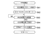
次に、図5のフローチャートを参照して、サブルーチン“FPN測定”の動作について説明する。
先ず、ステップS61にて、画像データコントローラ25に対して、イメージセンサ11の積分動作の開始が指示される。次いで、ステップS62では、測定時間(Ts)を測定するためのタイマカウンタのカウント動作が開始される。
【0075】
そして、ステップS63に於いて、タイマカウンタのカウント値がTsに達するまで待機される。次いで、ステップS64では、画像データコントローラ25に対して、イメージセンサ11の積分の停止が指示される。
【0076】
更に、ステップS65では、画像データコントローラ25により、イメージセンサ11から画像データの読込みが指示される。本サブルーチンが実行される時、イメージセンサ11は遮光されている。したがって、読込まれた画像データはFPNデータである。このデータは、DRAM29のエリア0へ記憶される。
【0077】
その後、メインルーチンへ復帰する。
また、本サブルーチンでは、イメージセンサ11の積分動作1回でFPNのデータを決定しているが、複数回イメージセンサ11の積分動作を行って画像データを取り込み、平均値を求めても良い。このようにすれば、より正確なFPNデータを得ることができる。
【0078】
尚、この発明の上記実施の形態によれば、以下の如き構成を得ることができる。
(1) 撮像素子と、
被写体光の撮像素子への透光と遮光を制御する遮光手段と、
この遮光手段の遮光状態にて上記撮像素子から画像データを読出す第1読出し手段と、
上記遮光手段の透光状態にて上記撮像素子から画像データを読出す第2読出し手段と、
上記第1読出し手段の画像データに基いて第2読出し手段の画像データに補正を行う画像補正手段と、
を具備し、
連続撮影モードと単発撮影モードとが選択可能であって、連続撮影モードが選択されているとき、複数回の第2読出し手段の動作に対して一回のみ第1読出し手段の作動を許可することを特徴とする電子カメラ。
【0079】
【発明の効果】
以上のようにこの発明によれば、積分時間や読出し時間の増加によるレリーズタイムラグの増大や、連続撮影速度の低下を防止して、画像データから固定パターンノイズの除去を正しく実行可能な電子カメラを提供することができる。
【図面の簡単な説明】
【図1】この発明の第1の実施の形態の構成を示すもので、電子撮像カメラのブロック構成図である。
【図2】システムコントローラ15のメインルーチンの動作を説明するフローチャートである。
【図3】システムコントローラ15のメインルーチンの動作を説明するフローチャートである。
【図4】サブルーチン“露光動作”の処理について説明するフローチャートである。
【図5】サブルーチン“FPN測定”の動作について説明するフローチャートである。
【符号の説明】
1 撮影レンズ、
2 絞り、
3 クイックリターンミラー、
5 AFセンサ、
7 接眼レンズ、
9 フィルタ、
10 フォーカルプレーンシャッタ、
11 イメージセンサ、
15 システムコントローラ(CPU)、
16 レンズ駆動機構、
17 絞り駆動機構、
18 ミラー駆動機構、
19 シャッタチャージ機構、
20 シャッタ制御回路、
21 温度センサ、
22 測光センサ、
23 EEPROM、
25 画像データコントローラ(DSP)、
29 DRAM、
32 画像表示回路、
33 画像圧縮回路、
34 画像データ記録メディア、
36 動作表示回路、
37 操作スイッチ(SW)。[0001]
BACKGROUND OF THE INVENTION
The present invention relates to an electronic camera that captures a subject image using an image sensor, and more particularly to an electronic camera that eliminates fixed pattern noise in an electronic camera using a solid-state image sensor.
[0002]
[Prior art]
2. Description of the Related Art Conventionally, as described in, for example, Japanese Patent Laid-Open No. 8-51571, an electronic imaging apparatus has an image sensor and an exposure control shutter that controls light transmission of subject light to the image sensor. In this electronic image pickup apparatus, after reading out image data from the image pickup element in the light-transmitting state of the shutter, the image from the image pickup element is measured in the light-shielded state of the shutter in order to measure fixed pattern noise (FPN) of the image pickup element. Data is read out. Then, image data not including fixed pattern noise is generated from the two image data.
[0003]
[Problems to be solved by the invention]
Incidentally, since the fixed pattern noise varies depending on the exposure time and temperature of the image sensor, it is desirable to measure the data of the fixed pattern noise every time photographing is performed in order to completely remove the fixed pattern noise from the image data.
[0004]
However, in order to measure the fixed pattern noise for each photographing as described above, the charge accumulation operation is performed twice for the image pickup device in one photographing operation. Need time.
[0005]
In recent years, the number of pixels of the image sensor has been increasing in order to improve the image quality of digital cameras. An increase in the number of pixels leads to an increase in the readout time of image data from the image sensor. Therefore, if fixed pattern noise data is measured each time, the readout time is also doubled.
[0006]
These increases in the integration time and readout time increase the release time lag and decrease the continuous shooting speed in the camera operation sequence.
The present invention has been made in view of the above problems, and prevents fixed pattern noise from image data correctly by preventing an increase in release time lag due to an increase in integration time and readout time and a decrease in continuous shooting speed. An object is to provide a possible electronic camera.
[0007]
[Means for Solving the Problems]
Shutter That the present invention, at a continuous shooting mode and the single shot mode selectable electronic camera, which controls an imaging device that outputs the image data by capturing a subject image, the exposure amount to the upper SL imaging element A first exposure operation in which the exposure time is calculated according to the subject brightness, the shutter is opened and the image data at the exposure time is taken from the image sensor, and the shutter is closed and the correction data is transferred to the image sensor. a second exposure operation for taking from the executable control circuit, the correction operation of correcting the image data captured by the second exposure operation captured by the correction data to be had based Dzu the first exposure operation anda correction circuit for performing, the single shot mode is selected and the single shot mode in shooting is performed, executing the first exposure operation and the second exposure operation when the same exposed seconds after it performs the correction operation, the communication Mode is selected and in the continuous photographing is performed in this continuous shooting mode, multiple of the first run only the second exposure operation once for the exposure operation, the plurality of the first exposure When performing the correction operation on each image data obtained by the operation, the correction data according to the ratio between the exposure time of each image data and the exposure time when the correction data is obtained by the second exposure operation and converting the.
[0009]
In the electronic camera capable of selecting the continuous shooting mode and the single shooting mode of the present invention, a subject image is picked up by the image pickup device and image data is output, and the exposure amount to the image pickup device is controlled by a shutter. . Then, the exposure time is calculated according to the subject brightness, the first exposure operation for opening the shutter and capturing the image data at the exposure time from the image sensor, and closing the shutter and the correction data as the image sensor. The second exposure operation to be taken in can be executed by the control circuit. The correction circuit performs a correction operation for correcting the image data acquired in the first exposure operation based on the correction data acquired in the second exposure operation. When the single shooting mode is selected and shooting is performed in the single shooting mode, the correction operation is performed after the first exposure operation and the second exposure operation are performed in the same exposure time. When the continuous shooting mode is selected and continuous shooting is performed in the continuous shooting mode, the second exposure operation is executed only once for the plurality of first exposure operations. When the correction operation is performed on each image data obtained by the first exposure operation, the ratio of the exposure time of each image data to the exposure time at the time of obtaining correction data by the second exposure operation The correction data is converted according to the above.
[0011]
DETAILED DESCRIPTION OF THE INVENTION
Embodiments of the present invention will be described below with reference to the drawings.
FIG. 1 shows a configuration of a first embodiment of the present invention and is a block configuration diagram of an electronic imaging camera.
[0012]
In FIG. 1, a photographic light beam from a subject image (not shown) is guided to a
[0013]
On the other hand, the photographing light beam reflected by the
When the
[0014]
When the
The
[0015]
The
The
[0016]
The
[0017]
The front and rear curtains of the focal plane shutter 10 have a drive source constituted by a spring, and a spring charge is required for the next operation after the shutter travels. The
[0018]
An
[0019]
The
[0020]
The
[0021]
An
[0022]
The
[0023]
The
[0024]
Further, the
[0025]
The
Next, the operation of the main routine of the
[0026]
2 and 3 are flowcharts for explaining the operation of the main routine of the
When a power switch that is one of the operation switches 37 is turned on and power is supplied to the system, the operation of the
[0027]
Next, in step S2, the capacity of the
[0028]
In step S3, a photometric operation is performed. In this photometric operation, first, luminance data of an object is input from the
[0029]
In step S4, data indicating the operation state of the camera (shutter time, aperture value, movement mode, etc.) is output to the
[0030]
Next, in step S5, the state of a release switch that is one of the operation switches 37 is detected. If the release switch is on, the process proceeds to step S10. If the release switch is off, the process proceeds to step S6.
[0031]
In step S6, the exposure counter (CNTexp) is cleared (← “0”) and the exposure prohibition flag is cleared (← “0”). The exposure counter indicates the number of continuous shooting operations during the continuous shooting mode. When the continuous shooting mode is not set (in the single shooting mode), the shooting operation is permitted only once every time the release switch is pressed. An exposure prohibition flag is used to establish this operation.
[0032]
In the subsequent step S7, the state of the power switch that is one of the operation switches is detected. Here, since the operation is continued if the power switch is on, the process proceeds to step S3. On the other hand, if the power switch is in the OFF state, the process proceeds to step S9, processing necessary for system down is executed, and the operation of the
[0033]
On the other hand, in step S10, the state of the continuous shooting mode switch which is one of the operation switches is detected. If this switch is on, the continuous shooting mode is set, and the process proceeds to step S18. On the other hand, if the continuous shooting mode switch is off, it indicates the single shooting mode, and the process proceeds to step S11.
[0034]
In step S11, the state of the exposure prohibition flag is detected. Here, if the flag is “1”, it means that the user has held the release switch even after the exposure operation is completed. In this case, since the exposure operation cannot be performed, the process proceeds to step S3.
[0035]
On the other hand, if the user releases the release switch to turn it off, the flag is cleared in step S6, and the exposure operation becomes possible. On the other hand, if the flag is “0”, the process proceeds to step S12 and a focus adjustment operation is performed. That is, information regarding the amount of focus shift is input from the AF sensor 5, and the
[0036]
Next, in step S13, a subroutine “exposure operation” is executed. By this operation, image data is taken in from the image sensor 11 under the exposure condition (Ts) calculated in step S3. Subsequently, in step S14, a subroutine “FPN (fixed pattern noise) measurement” is executed, and FPN data of the image sensor 11 is captured.
[0037]
In step S15, the
[0038]
In step S16, the
[0039]
Next, in step S17, an exposure prohibition flag is set (← "1") so that the exposure operation cannot be performed continuously. Thereafter, the process proceeds to step S3.
[0040]
On the other hand, in step S18, the FPN measurement prohibition flag is cleared (← “0”). During the continuous shooting operation in the continuous shooting mode, the FPN measurement operation is permitted only once. In order to establish this operation, the FPN measurement prohibition flag is used. This flag is set (← “1”) after the FPN measurement.
[0041]
In step S20, a focus adjustment operation is executed. Since the operation in step S20 is the same as that in step S12 described above, description thereof is omitted. Next, in step S21, a subroutine “exposure operation” is executed. With this operation, image data is taken in from the image sensor 11 under the calculated exposure condition.
[0042]
In step S22, the exposure counter (CNTexp) is incremented (+1). Subsequently, in step S23, the exposure time (Ts) of the image sensor 11 is stored in the memory of the
Here, Ts is necessary when correcting the image data based on the FPN data. Table 1 below is an example showing the contents of a memory map storing Ts.
[0043]
[Table 1]
Next, in step S24, the CNTexp and Nlimit are compared. This Nlimit is the number of frames that can be continuously shot set in step S2. If CNTexp and Nlimit are not equal in step S24, it indicates that there is still an area in the
[0045]
Here, if the release switch is ON, the photographing operation is continuously performed, and the process proceeds to step S19. Then, in order to prevent a problem even if the subject condition changes, a photometric operation (step S19) and a focus adjustment operation (step S20) are performed. Then, after the exposure operation (step S21), CNTexp is incremented (step S22). Then, the new Ts is stored in the memory of the system controller 15 (step S23).
[0046]
Thus, every time the exposure operation is performed, the value of CNTexp is incremented. When Nlimit is reached in step S24, the process proceeds to step S26.
In step S26, the
[0047]
In step S24, when CNTexp and Nlimit are equal, it indicates that the
[0048]
On the other hand, if the release switch is turned off by the user before CNTexp reaches Nlimit in step S24, the process proceeds to step S27 without displaying this warning.
[0049]
In step S27, the state of the FPN measurement prohibition flag is determined. If this flag is “0”, it indicates that the FPN data is not measured, and the process proceeds to step S28. On the other hand, if the flag is “1”, the image data may be corrected by the FPN data existing on the
[0050]
In step S28, the subroutine “FPN measurement” is executed. In order to prohibit this FPN measurement operation thereafter, the FPN prohibition flag is set (← “0”) in step S29. Next, in step S30, the second time (Ts) at the time of FPN measurement is stored in the memory of the
[0051]
On the other hand, in step S31, Tfpn and Ts stored in step S23 are used to perform a conversion operation on the FPN data. Even during the continuous shooting operation, since the photometry operation is performed in step S19, the shutter time of each captured image data is not necessarily the same. The fixed pattern noise includes only data measured under the condition of shutter speed Tfpn. The size of the FPN data changes in proportion to the shutter speed. Therefore, it is necessary to convert according to the shutter time of each image data.
[0052]
This operation is performed in step S31.
For ease of explanation, it is assumed that image data is recorded in the
[0053]
[Table 2]
The
[0055]
In the example shown here, the value of Nlimit is “10”, and the value of CNTexp is “10”, so that the operation has shifted to step S31. This indicates that the image recording area of the
[0056]
Accordingly, in step S31, the
[0057]
In the
FPNn ′ = FPNn × Ts / Tfpn
FPNn: noise data of one pixel before conversion (n = 1, 2, 3,...),
FPNn ′: Noise data of one pixel after conversion (n = 1, 2, 3,...)
In step S32, the
[0058]
In step S33, the
[0059]
In step S34, CNTexp is decremented (-1). In this case, CNTexp becomes “9”. Next, in step S35, the parameter Nopen is read from the
[0060]
If the difference is greater than Nopen, the process proceeds to step S37. If the difference is less than Nopen, the process proceeds to step S31. Nopen is set to a value of “1 or more”. By changing Nopen, it is possible to arbitrarily set the exposure operation to be permitted when the number of empty areas on the
[0061]
If it is desired to prohibit the exposure operation until the image data area on the
[0062]
On the other hand, in step S37, the warning display started in step S26 is terminated, and the user is notified that the exposure operation is possible. Next, in step S38, the state of the release switch is detected. If the release switch is ON, the process proceeds to step S19 because an exposure operation is performed. Then, the exposure operation (steps S19 to S21) is performed until there is no empty area in the area of the
[0063]
In step S38, when the process proceeds to step S39 because the release switch is OFF, it is determined whether or not CNTexp is "0". Here, if CNTexp is not “0”, it means that image data remains on the
[0064]
In step S39, if CNTexp is "0", it means that all the image data on the
[0065]
As described above, in this embodiment, when the release switch is turned off during the continuous shooting operation, or when there is no more area in which image data is taken into the
[0066]
However, a method of performing a fixed pattern noise measurement operation immediately before starting a continuous shooting operation is also conceivable. In this case, the flowchart may be modified as follows.
[0067]
That is, step S18 is deleted, and the same processing operation as step S28 and step S30 is performed at this point. And since the processing operation of step S27-S30 is unnecessary, it deletes.
[0068]
Next, the subroutine “exposure operation” will be described with reference to the flowchart of FIG.
In step S41, the
[0069]
In step S43, a shutter front curtain start signal is output to the
[0070]
Thereafter, in step S46, an instruction is issued to the
[0071]
In step S49, the
[0072]
In steps S51 and S52, the
[0073]
In step S54, the diaphragm is driven to the open position. Next, in step S55, the
[0074]
Next, the operation of the subroutine “FPN measurement” will be described with reference to the flowchart of FIG.
First, in step S61, the
[0075]
In step S63, the process waits until the count value of the timer counter reaches Ts. Next, in step S64, the
[0076]
In step S65, the
[0077]
Thereafter, the process returns to the main routine.
Further, in this subroutine, the FPN data is determined by one integration operation of the image sensor 11. However, the integration operation of the image sensor 11 may be performed a plurality of times to acquire image data, and the average value may be obtained. In this way, more accurate FPN data can be obtained.
[0078]
In addition, according to the said embodiment of this invention, the following structures can be obtained.
(1) an image sensor;
Light blocking means for controlling light transmission and light blocking of the subject light to the image sensor;
First reading means for reading image data from the imaging device in a light-shielding state of the light-shielding means;
Second reading means for reading image data from the imaging element in a light-transmitting state of the light shielding means;
Image correcting means for correcting the image data of the second reading means based on the image data of the first reading means;
Comprising
When the continuous shooting mode and the single shooting mode are selectable and the continuous shooting mode is selected, the operation of the first reading means is permitted only once for the plurality of times of the operation of the second reading means. An electronic camera characterized by
[0079]
【The invention's effect】
As described above, according to the present invention, there is provided an electronic camera capable of correctly removing fixed pattern noise from image data while preventing an increase in release time lag due to an increase in integration time and readout time and a decrease in continuous shooting speed. Can be provided.
[Brief description of the drawings]
FIG. 1 is a block diagram of an electronic imaging camera, showing the configuration of a first embodiment of the present invention.
FIG. 2 is a flowchart for explaining the operation of a main routine of the
FIG. 3 is a flowchart for explaining the operation of the main routine of the
FIG. 4 is a flowchart illustrating processing of a subroutine “exposure operation”.
FIG. 5 is a flowchart illustrating an operation of a subroutine “FPN measurement”.
[Explanation of symbols]
1 Shooting lens,
2 Aperture,
3 Quick return mirror,
5 AF sensor,
7 Eyepiece,
9 Filter,
10 Focal plane shutter,
11 Image sensor,
15 system controller (CPU),
16 Lens drive mechanism,
17 Aperture drive mechanism,
18 mirror drive mechanism,
19 Shutter charge mechanism,
20 shutter control circuit,
21 temperature sensor,
22 Photometric sensor,
23 EEPROM,
25 Image data controller (DSP),
29 DRAM,
32 Image display circuit,
33 Image compression circuit,
34 Image data recording media,
36 operation display circuit,
37 Operation switch (SW).
Claims (3)
被写体像を撮像して画像データを出力する撮像素子と、
上記撮像素子への露光量を制御するシャッタと、
被写体輝度に応じて露出秒時を算出し、上記シャッタを開いてこの露出秒時の画像データを上記撮像素子から取込む第1露光動作と、上記シャッタを閉じて補正データを上記撮像素子から取込む第2露光動作と、を実行可能な制御回路と、
上記第2露光動作で取込まれた補正データに基づいて上記第1露光動作で取込まれた画像データを補正する補正動作を行う補正回路と、
を有し、
上記単写モードが選択され、この単写モードに於ける撮影が行われると、上記第1露光動作と第2露光動作とを同一の露出秒時で実行後、上記補正動作を実行し、
上記連写モードが選択され、この連写モードに於ける連続撮影が行われると、複数回の上記第1露光動作に対して1回のみ上記第2露光動作を実行し、この複数回の上記第1露光動作で得られた各々の画像データに対して上記補正動作を行うに際して、各画像データの露出秒時と上記第2露光動作で補正データを得る際の露出秒時との比に応じて補正データを変換する
ことを特徴とする電子カメラ。In an electronic camera that can select between continuous shooting mode and single shooting mode,
An image sensor that captures a subject image and outputs image data;
A shutter for controlling the exposure amount to the upper Symbol imaging device,
The exposure time is calculated according to the subject brightness, the first exposure operation for opening the shutter and capturing the image data at the exposure time from the image sensor, and the correction data from the image sensor by closing the shutter. A control circuit capable of performing a second exposure operation
A correction circuit for performing a correction operation for correcting the image data captured the second and have groups Dzu the correction data captured in the exposure operation in the first exposure operation,
Have
When the single shooting mode is selected and shooting in the single shooting mode is performed, the correction operation is performed after the first exposure operation and the second exposure operation are performed in the same exposure time ,
When the continuous shooting mode is selected and continuous shooting is performed in the continuous shooting mode, the second exposure operation is executed only once for the plurality of first exposure operations. When performing the correction operation on each image data obtained by the first exposure operation, the ratio of the exposure time of each image data to the exposure time at the time of obtaining correction data by the second exposure operation An electronic camera characterized by converting correction data .
Priority Applications (1)
| Application Number | Priority Date | Filing Date | Title |
|---|---|---|---|
| JP31919398A JP4187327B2 (en) | 1998-11-10 | 1998-11-10 | Electronic camera |
Applications Claiming Priority (1)
| Application Number | Priority Date | Filing Date | Title |
|---|---|---|---|
| JP31919398A JP4187327B2 (en) | 1998-11-10 | 1998-11-10 | Electronic camera |
Publications (3)
| Publication Number | Publication Date |
|---|---|
| JP2000152097A JP2000152097A (en) | 2000-05-30 |
| JP2000152097A5 JP2000152097A5 (en) | 2005-11-10 |
| JP4187327B2 true JP4187327B2 (en) | 2008-11-26 |
Family
ID=18107460
Family Applications (1)
| Application Number | Title | Priority Date | Filing Date |
|---|---|---|---|
| JP31919398A Expired - Fee Related JP4187327B2 (en) | 1998-11-10 | 1998-11-10 | Electronic camera |
Country Status (1)
| Country | Link |
|---|---|
| JP (1) | JP4187327B2 (en) |
Families Citing this family (6)
| Publication number | Priority date | Publication date | Assignee | Title |
|---|---|---|---|---|
| JP4892802B2 (en) * | 2001-08-30 | 2012-03-07 | 株式会社ニコン | Electronic camera |
| JP4532819B2 (en) | 2002-11-20 | 2010-08-25 | キヤノン株式会社 | Imaging device |
| JP2009017078A (en) * | 2007-07-03 | 2009-01-22 | Fujifilm Corp | Digital still camera and its operation controlling method |
| JP2010212741A (en) * | 2007-07-05 | 2010-09-24 | Konica Minolta Medical & Graphic Inc | Radio ray image detection device |
| JP5365633B2 (en) * | 2008-07-03 | 2013-12-11 | 株式会社ニコン | Imaging device |
| JP6126491B2 (en) * | 2013-08-08 | 2017-05-10 | キヤノン株式会社 | Imaging apparatus, control method therefor, program, and storage medium |
-
1998
- 1998-11-10 JP JP31919398A patent/JP4187327B2/en not_active Expired - Fee Related
Also Published As
| Publication number | Publication date |
|---|---|
| JP2000152097A (en) | 2000-05-30 |
Similar Documents
| Publication | Publication Date | Title |
|---|---|---|
| JP2001177761A (en) | Digital camera | |
| JP2001186401A (en) | Digital camera | |
| JP2008053843A (en) | Digital camera capable of recording motion picture | |
| JP5116397B2 (en) | Imaging apparatus and control method thereof | |
| JP4187327B2 (en) | Electronic camera | |
| JP4146944B2 (en) | Electronic camera | |
| US20090185069A1 (en) | Imaging apparatus and control method thereof | |
| JP2023159227A (en) | Imaging apparatus | |
| JP4763941B2 (en) | Display control device, control method, program, and recording medium | |
| JP4146945B2 (en) | Electronic camera | |
| JP5961058B2 (en) | Imaging apparatus and control method thereof, image processing apparatus and control method thereof | |
| JP4146948B2 (en) | Electronic camera | |
| JP2008245129A (en) | Electronic camera and control method thereof | |
| US7884867B2 (en) | Lens apparatus and image-pickup apparatus | |
| JP4838460B2 (en) | Imaging device | |
| JP4974862B2 (en) | Imaging apparatus and control method thereof | |
| JP2780797B2 (en) | Electronic imaging device | |
| JP2007267330A (en) | Digital single-lens reflex camera | |
| JP5463657B2 (en) | camera | |
| JP4780877B2 (en) | Electronic camera and control method | |
| JP2008052151A (en) | Digital camera capable of recording moving picture | |
| JPH06205288A (en) | Electronic still camera and still video pack | |
| JP2007025129A (en) | Exposure setting method and device | |
| JP2000134545A (en) | Electronic camera | |
| JPH10142686A (en) | Silver salt camera having monitor screen |
Legal Events
| Date | Code | Title | Description |
|---|---|---|---|
| A521 | Request for written amendment filed |
Free format text: JAPANESE INTERMEDIATE CODE: A523 Effective date: 20050921 |
|
| A621 | Written request for application examination |
Free format text: JAPANESE INTERMEDIATE CODE: A621 Effective date: 20050921 |
|
| A977 | Report on retrieval |
Free format text: JAPANESE INTERMEDIATE CODE: A971007 Effective date: 20080606 |
|
| A131 | Notification of reasons for refusal |
Free format text: JAPANESE INTERMEDIATE CODE: A131 Effective date: 20080617 |
|
| A521 | Request for written amendment filed |
Free format text: JAPANESE INTERMEDIATE CODE: A523 Effective date: 20080808 |
|
| TRDD | Decision of grant or rejection written | ||
| A01 | Written decision to grant a patent or to grant a registration (utility model) |
Free format text: JAPANESE INTERMEDIATE CODE: A01 Effective date: 20080902 |
|
| A01 | Written decision to grant a patent or to grant a registration (utility model) |
Free format text: JAPANESE INTERMEDIATE CODE: A01 |
|
| A61 | First payment of annual fees (during grant procedure) |
Free format text: JAPANESE INTERMEDIATE CODE: A61 Effective date: 20080909 |
|
| FPAY | Renewal fee payment (event date is renewal date of database) |
Free format text: PAYMENT UNTIL: 20110919 Year of fee payment: 3 |
|
| FPAY | Renewal fee payment (event date is renewal date of database) |
Free format text: PAYMENT UNTIL: 20120919 Year of fee payment: 4 |
|
| FPAY | Renewal fee payment (event date is renewal date of database) |
Free format text: PAYMENT UNTIL: 20130919 Year of fee payment: 5 |
|
| S531 | Written request for registration of change of domicile |
Free format text: JAPANESE INTERMEDIATE CODE: R313531 |
|
| R350 | Written notification of registration of transfer |
Free format text: JAPANESE INTERMEDIATE CODE: R350 |
|
| LAPS | Cancellation because of no payment of annual fees |