JP4974862B2 - Imaging apparatus and control method thereof - Google Patents
Imaging apparatus and control method thereof Download PDFInfo
- Publication number
- JP4974862B2 JP4974862B2 JP2007308970A JP2007308970A JP4974862B2 JP 4974862 B2 JP4974862 B2 JP 4974862B2 JP 2007308970 A JP2007308970 A JP 2007308970A JP 2007308970 A JP2007308970 A JP 2007308970A JP 4974862 B2 JP4974862 B2 JP 4974862B2
- Authority
- JP
- Japan
- Prior art keywords
- photometric
- difference
- photometric data
- predetermined value
- absolute value
- Prior art date
- Legal status (The legal status is an assumption and is not a legal conclusion. Google has not performed a legal analysis and makes no representation as to the accuracy of the status listed.)
- Expired - Fee Related
Links
Images


Description
本発明は、撮像装置及びその制御方法に関し、特に複数の測光方式を備えた撮像装置に関する。 The present invention relates to an imaging apparatus and a control method thereof, and more particularly to an imaging apparatus having a plurality of photometry methods.
被写体像を記録する撮像装置として、被写体像を光電変換し、所定の処理を施した後に記録する所謂ディジタルカメラが知られている。ディジタルカメラにおいては、その露出値決定に際しての測光手段や制御方法は従前の銀塩フィルムを使用するカメラと同様の手段、方法が用いられている。 As an imaging device for recording a subject image, a so-called digital camera is known in which a subject image is photoelectrically converted and recorded after being subjected to predetermined processing. In a digital camera, the same means and method as those of a camera using a conventional silver salt film are used as a photometric means and control method for determining the exposure value.
そこで、自動露出機能を有し、かつ連続撮影可能な撮像装置の制御方法に関する発明が提案されている。 Therefore, an invention relating to a method for controlling an image pickup apparatus having an automatic exposure function and capable of continuous shooting has been proposed.
この方法では、連写中に被写体輝度が急激に変化した際などには予め記憶させてあった設定露出値を用いて撮影することにより、例えば移動する被写体が日向から日陰に入ってくるようなシーンにおける露出制御に対応していた(特許文献1参照)。
しかしながら、特許文献1に記載された方法では、測光領域が撮影画面に比して狭いスポット測光使用時に連続で撮影を行った際には以下のような問題が起こることがある。
However, in the method described in
例えば、被写体の動きなどによって撮影画像間でスポット測光の対象となる領域の輝度変化があった場合、予め設定された露出値で露出制御を行うことになる。 For example, when there is a change in the brightness of a region that is subject to spot metering between captured images due to the movement of a subject or the like, exposure control is performed with a preset exposure value.
しかし、それでは狙った領域の露出が最適になるように測光を行うというスポット測光の機能を活かせていないという問題があった。 However, there is a problem that the spot metering function of performing the metering so that the exposure of the target area is optimized is not utilized.
上記目的を達成するために、本発明に係る撮像装置は、測光を行い、第1の測光領域から得られる第1の測光データと、前記第1の測光領域よりも広く当該第1の測光領域を含む第2の測光領域から得られる第2の測光データとを出力可能な測光手段と、連続して得られる2つの前記第1の測光データの差分である第1の差分を算出する第1の算出手段と、連続して得られる2つの前記第2の測光データの差分である第2の差分を算出する第2の算出手段と、前記第1の差分の絶対値が第1の所定値以上の場合、前記第2の差分に基づいて露出制御に用いる測光データを選択する選択手段と、を有することを特徴とする。 To achieve the above object, an imaging apparatus according to the present invention performs photometry, and the first photometric data obtained from the first metering area, broadly the first metering area than the first metering area A first photometric unit that can output second photometric data obtained from a second photometric region including the first photometric data, and a first difference that is a difference between the two first photometric data obtained successively. Calculating means, second calculating means for calculating a second difference that is a difference between two pieces of second photometric data obtained successively, and an absolute value of the first difference being a first predetermined value In the above case, there is provided selection means for selecting photometric data used for exposure control based on the second difference .
また、上記目的を達成するために、本発明に係る撮像装置の制御方法は、測光を行い、第1の測光領域から得られる第1の測光データと、前記第1の測光領域よりも広く当該第1の測光領域を含む第2の測光領域から得られる第2の測光データとを出力可能な測光手段を有する撮像装置の制御方法であって、連続して得られる2つの前記第1の測光データの差分である第1の差分を算出する第1の算出ステップと、連続して得られる2つの前記第2の測光データの差分である第2の差分を算出する第2の算出ステップと、前記第1の差分の絶対値が第1の所定値以上の場合、前記第2の差分に基づいて露出制御に用いる測光データを選択する選択ステップと、を有することを特徴とする。 In order to achieve the above object, a control method of an imaging apparatus according to the present invention performs photometry, and the first photometric data obtained from the first metering area wider the than the first metering area A method for controlling an imaging apparatus having a photometric means capable of outputting second photometric data obtained from a second photometric area including the first photometric area, wherein the two first photometry are obtained continuously. A first calculation step for calculating a first difference that is a difference between data; a second calculation step for calculating a second difference that is a difference between two second photometric data obtained successively; A selection step of selecting photometric data used for exposure control based on the second difference when the absolute value of the first difference is equal to or greater than a first predetermined value .
本発明によれば、被写体が好適な露出となるような露出制御を行うことが可能になる。 According to the present invention, it is possible to perform exposure control such as the Utsushitai is suitable exposure.
以下、本発明に係る一実施形態について図面を参照して詳細に説明する。
なお、以下に説明する実施形態は、本発明を実現するための一例であり、本発明が適用される装置の構成や各種条件によって適宜修正又は変更されるべきものであり、本発明は以下の実施形態に限定されるものではない。
Hereinafter, an embodiment according to the present invention will be described in detail with reference to the drawings.
The embodiment described below is an example for realizing the present invention, and should be appropriately modified or changed according to the configuration and various conditions of the apparatus to which the present invention is applied. It is not limited to the embodiment.
<第1の実施形態>
本発明の第1の実施形態について説明する。図1は第1の実施形態に係る撮像装置の構成を示すブロック図である。
<First Embodiment>
A first embodiment of the present invention will be described. FIG. 1 is a block diagram illustrating a configuration of an imaging apparatus according to the first embodiment.
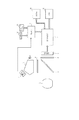
同図において1はレンズ、2は可動する主ミラー、3は遮光幕としてのシャッター、4はピント板、5はミラーで鉛直方向に反射された光を2回反射させて接眼レンズに導くペンタプリズムである。 In the figure, 1 is a lens, 2 is a movable main mirror, 3 is a shutter as a light-shielding curtain, 4 is a focusing plate, and 5 is a pentaprism that reflects light reflected by the mirror in the vertical direction twice to guide the eyepiece. It is.
6は撮影光学系により形成された被写体像を光電変換するCCDセンサやCMOSセンサ等の光電変換機能を有する撮像素子である。 Reference numeral 6 denotes an image pickup device having a photoelectric conversion function such as a CCD sensor or a CMOS sensor that photoelectrically converts a subject image formed by the photographing optical system.
7は撮像素子6の出力に対して、A/D変換等の所定の処理を行い、画像信号を生成する信号処理部、8は自動合焦、露出制御を始めとする撮像装置の各種制御をおこなう制御部である。 Reference numeral 7 denotes a signal processing unit that performs predetermined processing such as A / D conversion on the output of the image sensor 6 and generates an image signal. Reference numeral 8 denotes various controls of the imaging apparatus including automatic focusing and exposure control. It is a control part to perform.
9は被写界の明るさを測定しその結果を出力可能な測光センサ(測光手段)、10は撮像装置本体に着脱自在の撮影画像等を記録するメモリ、11は撮像装置背面に設けられた画像等を表示する液晶モニタなどで構成される表示部である。
12は撮像装置の測光モードを設定可能な設定部材、13は撮影の開始を指示するレリーズボタンである。
9 is a photometric sensor (photometric means) capable of measuring the brightness of the object field and outputting the result, 10 is a memory for recording a photographed image that can be attached to and detached from the image pickup apparatus body, and 11 is provided on the back of the image pickup apparatus. It is a display part comprised with the liquid crystal monitor etc. which display an image etc.
不図示の被写体像はレンズ1を通して、主ミラー2で反射されて撮像素子6と共役な位置にあるピント板4上に結像する。
A subject image (not shown) is reflected by the main mirror 2 through the
ピント板4上の被写体像はペンタプリズム5を経て撮影者によって観察されるとともに、ピント板4にて拡散された被写体像の光束の一部は測光センサ9へと入射し被写体光が測定される。 The subject image on the focus plate 4 is observed by the photographer through the pentaprism 5, and part of the light flux of the subject image diffused by the focus plate 4 is incident on the photometric sensor 9 to measure the subject light. .
図2は本実施形態における、第1の測光領域、及び、第2の測光領域を示す図である。
図2において、(a)は撮影領域の中心部5%程度の面積を測光する第1の測光領域としてのスポット領域であり、(b)はスポット測光領域を含み、それよりも広い撮影領域の中心部15%程度の面積を測光する第2の測光領域としての部分測光領域である。
FIG. 2 is a diagram showing a first photometry area and a second photometry area in the present embodiment.
In FIG. 2, (a) is a spot area as a first photometry area that measures the area of about 5% of the central area of the imaging area, and (b) includes a spot photometry area, which is a wider imaging area. This is a partial photometry area as a second photometry area that measures the area of about 15% of the center.
測光センサ9は、第1の測光領域から得られた第1の測光データと、第2の測光領域からえられた第2の測光データの2種類の測光データを出力する。
そして、第1の測光データ及び第2の測光データは制御部8に入力される。
The photometric sensor 9 outputs two types of photometric data, the first photometric data obtained from the first photometric area and the second photometric data obtained from the second photometric area.
Then, the first photometry data and the second photometry data are input to the control unit 8.
設定部材12によって測光モードとしてスポット測光モードが選択され、単写モードでの撮影を行う場合、又は、スポット測光モードが選択され、連写モードにおける1齣目の撮影を行う場合は、第1の測光データを制御部8に出力する。
When the spot metering mode is selected as the metering mode by the
そして、制御部8は、第1の測光データに基づいて、シャッタースピード、絞り値、信号増幅率をそれぞれ決定する。 Then, the control unit 8 determines a shutter speed, an aperture value, and a signal amplification factor based on the first photometric data.
設定部材12によって撮影モードとして連写モードが選択されている場合にはレリーズボタン13が押し下げられると一連の撮影シーケンスが実行される。そして、撮影シーケンス実行後にレリーズボタン13が引き続き押し下げられていた場合には引き続き次の齣の撮影シーケンスが開始される。
When the continuous shooting mode is selected as the shooting mode by the
なお、本実施形態においては、設定部材12によって、測光モード及び撮影モードを選択しているが、設定手段はこれに限られるわけではなく、表示部に設定用のメニューを表示してそこから選択するようにしてもよい。また、この設定部材12は、測光モード及び撮影モードの選択以外の撮影機能の選択を行うことが可能な汎用設定部材として扱うようにしてもよい。
In the present embodiment, the photometry mode and the shooting mode are selected by the
また、測光モードと撮影モードの選択を共通の部材(設定部材12)を用いて行っているが、それぞれ別の部材を遣って選択するようにしてもよい。 In addition, the photometry mode and the photographing mode are selected using a common member (setting member 12), but may be selected using different members.
スポット測光モードが選択されて、連写モードにおける2齣目以降の撮影が行われる場合には、第1の測光データ及び第2の測光データを用いて制御部8にて露出値が決定される。
以上の動作はレリーズボタン13が解放されるまで繰り返される。
When the spot photometry mode is selected and the second and subsequent shots are taken in the continuous shooting mode, the control unit 8 determines the exposure value using the first photometry data and the second photometry data. .
The above operation is repeated until the
撮影シーケンス中には制御部8からの制御信号に応じてレンズ1に備えられた不図示の絞りが所定の絞り値になるように制御され、主ミラー2がピント板4方向に退避し、所定のシャッタースピードでシャッター3が開閉する。
そして、撮像素子6上に結像した被写体像が光電変換されて電気信号として読み出される。
During the photographing sequence, the diaphragm (not shown) provided in the
The subject image formed on the image sensor 6 is photoelectrically converted and read as an electrical signal.
撮像素子6より読み出された画像信号は信号処理部7にて所定の処理を施された後、制御部8によってメモリ13に記録される。
The image signal read from the image sensor 6 is subjected to predetermined processing by the signal processing unit 7 and then recorded in the
図3は第1の実施形態における撮影シーケンスの動作を示すフローチャートである。以下、図に従って動作を説明する。 FIG. 3 is a flowchart showing the operation of the imaging sequence in the first embodiment. The operation will be described below with reference to the drawings.
撮像装置の不図示の電源が投入されると撮影待機状態となり、レリーズボタン13が押し下げられると、撮像装置はステップ100からの処理を開始する。
ステップS100では、設定部材12によって設定された測光モードに応じて露出値が決定される。
ステップS101では、主ミラー2が光路中から退避する。
ステップS102では、ステップS100で決定された露出値に従ってレンズ1の絞りが設定される。
ステップS103では、撮像素子7の蓄積動作が開始される。
ステップS104では、撮像素子7の蓄積動作の開始に連動してシャッター3が開かれる。
ステップS105では、所定時間が経過したか否かの判定を行い、所定時間が経過したと判定されると、制御部8は、処理をステップS106へ進める。なお、ここでの所定時間とは制御部8にて算出されたシャッタースピードに基づいて算出される。
ステップS106では、シャッター3が閉じられる。
ステップS107では、主ミラー2が光路中に復帰する。
ステップS108では、撮像素子6より撮影信号が読み出され、読み出しが完了すると、制御部8は、処理をステップS109へ進める。
ステップS109では、制御部8は、撮影モードを判定を行い、単写モードであると判定した場合には、撮影動作を終了させる。
ステップS109にて、制御部8は、撮影モードが連写モードであると判定した場合は、処理をステップS110に進める。
ステップS110では、制御部8は、画像信号の読み出しが完了してもレリーズボタン13が押されているか否かを判定し、レリーズボタン13が押し下げられていなければ撮影動作を終了する。
When a power supply (not shown) of the image pickup apparatus is turned on, the image pickup standby state is set. When the
In step S100, the exposure value is determined according to the photometry mode set by the
In step S101, the main mirror 2 is retracted from the optical path.
In step S102, the aperture of the
In step S103, the accumulation operation of the image sensor 7 is started.
In step S104, the shutter 3 is opened in conjunction with the start of the accumulation operation of the image sensor 7.
In step S105, it is determined whether or not a predetermined time has elapsed. If it is determined that the predetermined time has elapsed, the control unit 8 advances the process to step S106. Here, the predetermined time is calculated based on the shutter speed calculated by the control unit 8.
In step S106, the shutter 3 is closed.
In step S107, the main mirror 2 returns to the optical path.
In step S108, a photographing signal is read from the image sensor 6, and when the reading is completed, the control unit 8 advances the process to step S109.
In step S109, the control unit 8 determines the shooting mode. If it is determined that the mode is the single shooting mode, the control unit 8 ends the shooting operation.
If the control unit 8 determines in step S109 that the shooting mode is the continuous shooting mode, the process proceeds to step S110.
In step S110, the control unit 8 determines whether or not the
ステップS110にて、制御部8は、画像信号の読み出しが完了してもレリーズボタン13が押し下げられていると判定した場合には、処理をステップS100に戻して二齣目の撮影が行われる。
If the control unit 8 determines in step S110 that the
以下、レリーズボタン13が解放されるか、メモリ13の容量が不足するなどの他の要因で撮影継続が不可能となるまでS100からS110までの撮影シーケンスを繰り返す。
Hereinafter, the shooting sequence from S100 to S110 is repeated until the
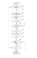
図4は図3におけるステップS100の露出値決定処理の詳細な動作フローを示したフローチャートである。以下、図に従って動作を説明する。 FIG. 4 is a flowchart showing a detailed operation flow of the exposure value determination process in step S100 in FIG. The operation will be described below with reference to the drawings.
図3のステップS100における露出値決定処理が開始されるとステップS201からの処理を始める。 When the exposure value determination process in step S100 of FIG. 3 is started, the process from step S201 is started.
ステップS200において、測光素子9は、スポット測光領域の測光データである第1の測光データ、及び、部分測光領域の測光データである第2の測光データを制御部8に出力する。 In step S <b> 200, the photometric element 9 outputs the first photometric data that is the photometric data of the spot photometric area and the second photometric data that is the photometric data of the partial photometric area to the control unit 8.
ステップS201において、撮影モードが単写モードの場合、及び連写モードにおける撮影の1齣目の場合は、制御部8は処理をステップS207に進めて、現在設定されている測光領域の測光データに基づいて露出値を決定する。 In step S201, if the shooting mode is the single shooting mode or the first shot in the continuous shooting mode, the control unit 8 advances the process to step S207 to obtain the photometric data of the currently set photometric area. Based on the exposure value.
ステップS201において、は制御部8は、撮影モードが連写モードにおける撮影の2齣目の場合は、処理をステップS202に進める。 In step S201, the control unit 8 advances the process to step S202 when the shooting mode is the second shooting mode in the continuous shooting mode.
ステップS202では、制御部8は、現在の撮影齣の第1の測光データと1齣前に撮影された画像の第1の測光データとを比較(第1の比較)し、差分(第1の差分)を算出する。 In step S202, the control unit 8 compares (first comparison) the first photometric data of the current photographing basket with the first photometric data of the image photographed one previous photograph, and the difference (first comparison). Difference) is calculated.
ステップS203では、ステップS202で算出した差分の絶対値が所定値以上か否かを判定する。ここで、設定されている所定値は、被写体がスポット測光領域にいるか、いないかを判定できる程度の値に設定されているものとする。 In step S203, it is determined whether or not the absolute value of the difference calculated in step S202 is greater than or equal to a predetermined value. Here, it is assumed that the set predetermined value is set to a value that can determine whether the subject is in the spot photometry area.
ステップS203にて、ステップS202で算出した差分の絶対値が所定値より小さいと判定された場合は、制御部8は処理をステップS207に進めて、現在設定されている測光領域の測光データに基づいて露出値を決定する。これは、直近の撮影画像との測光データの差分が所定値よりも小さいので、現在設定されている測光領域に被写体を捉えることができていると考えられるからである。 If it is determined in step S203 that the absolute value of the difference calculated in step S202 is smaller than the predetermined value, the control unit 8 advances the process to step S207, and based on the photometric data of the currently set photometric area. To determine the exposure value. This is because it is considered that the subject can be captured in the currently set photometric area because the difference between the photometric data and the most recently captured image is smaller than a predetermined value.
ステップS203にて、ステップS202で算出した差分の絶対値が所定値以上と判定された場合は、制御部8は処理をステップS204に進めてる。 If it is determined in step S203 that the absolute value of the difference calculated in step S202 is greater than or equal to a predetermined value, the control unit 8 advances the process to step S204.
ステップS204では、現在の撮影齣の第2の測光データと1齣前に撮影された画像の第2の測光データとを比較(第2の比較)し、差分(第2の差分)を算出する。 In step S204, the second photometric data of the current shooting rod is compared with the second photometric data of the image shot immediately before (second comparison), and a difference (second difference) is calculated. .
ステップS205では、ステップS204で算出した差分の絶対値が所定値以下か否かを判定する。ここで、設定されている第2の設定値としての所定値は、被写体が部分測光測光領域にいるか、いないかを判定できる程度の値に設定されているものとする。 In step S205, it is determined whether or not the absolute value of the difference calculated in step S204 is equal to or less than a predetermined value. Here, it is assumed that the predetermined value as the second set value that has been set is set to a value that can determine whether or not the subject is in the partial photometric photometry region.
ステップS205にて、ステップS204で算出した差分の絶対値が所定値より大きいと判定された場合は、制御部8は処理をステップS207に進めて、現在設定されている測光領域の測光データに基づいて露出値を決定する。 If it is determined in step S205 that the absolute value of the difference calculated in step S204 is larger than the predetermined value, the control unit 8 advances the process to step S207, and based on the photometric data of the currently set photometric area. To determine the exposure value.
これは、前後の撮影齣における第1の測光データの差分が大きく、又、前後の撮影齣における第2の測光データの差分も大きいので、周辺光の影響で測光領域が一様に明るく照らされた或いは、暗くなったことが考えられるからである。つまり、周辺光の影響で第1及び第2の測光データが変化しただけで、被写体自体が測光領域から外れたのではなく、測光領域の追従はできているとみなすことができるので、現在設定されている測光領域の測光データに基づいて露出値を決定する。 This is because the difference in the first photometric data between the front and rear photographing rods is large, and the difference between the second photometric data in the front and rear photographing rods is also large. This is because it may have been dark. In other words, it can be considered that the subject itself has not moved out of the photometry area, but has just followed the photometry area, only by changing the first and second photometry data due to the influence of ambient light. The exposure value is determined based on the photometric data of the photometric area.
ステップS205にて、ステップS204で算出した差分の絶対値が所定値以下であると判定された場合は、制御部8は処理をステップS206に進める。 If it is determined in step S205 that the absolute value of the difference calculated in step S204 is equal to or smaller than a predetermined value, the control unit 8 advances the process to step S206.
ステップS206では、ステップS204にて算出した差分を、前の撮影齣における第1の測光データに加味して、露出値を決定する。こうすることで、第1の測光流域にはいなくなったが、第2の領域では捕らえることができている被写体の露出を好適に制御することが可能になる。 In step S206, the exposure value is determined by adding the difference calculated in step S204 to the first photometric data in the previous photographing basket. By doing so, it becomes possible to suitably control the exposure of the subject that is no longer in the first photometric flow area but can be captured in the second area.
なお、本実施形態においては、ライブビューができない一眼レフカメラの構成を前提としているが、これに限られるわけではない。 In this embodiment, the configuration of a single-lens reflex camera that cannot perform live view is assumed, but the present invention is not limited to this.
ライブビュー可能な一眼デジタルカメラ、コンパクトデジタルカメラやビデオカメラ等においても、連写モードによる撮影時において、スポット測光モードが設定されている場合は同様の処理を行うことが可能であることは言うまでもない。 It goes without saying that the same processing can be performed even in single-lens digital cameras, compact digital cameras, video cameras, etc. capable of live view when the spot metering mode is set when shooting in continuous shooting mode. .
その際には、撮像素子が測光センサもかねることになるので、撮像素子6の出力を制御部にも送り、第1及び第2の測光データを算出する制御を行うことになる。 At that time, the image sensor also serves as a photometric sensor, and therefore, the output of the image sensor 6 is also sent to the control unit, and control for calculating the first and second photometric data is performed.
以上、本実施形態によれば、連写モードによる撮影時にスポット測光による測光を行う際に、スポット測光の対象領域よりも広い部分測光領域の測光値も加味して、被写体の移動判定を行っている。そのため、スポット測光領域のみを測光対象として露出制御を行うよりも精度の高い露出制御を行うことが可能になる。 As described above, according to the present embodiment, when performing photometry by spot metering during shooting in continuous shooting mode, subject movement determination is performed by taking into account the photometry value of a partial photometry area wider than the target area of spot metering. Yes. Therefore, it is possible to perform exposure control with higher accuracy than performing exposure control only on the spot photometry area.
<第2の実施形態>
以下、本発明の第2の実施形態について説明する。なお、撮像装置の構成について第1の実施形態と同様の構成については説明を割愛する。
<Second Embodiment>
Hereinafter, a second embodiment of the present invention will be described. In addition, about the structure of an imaging device, the structure similar to 1st Embodiment is abbreviate | omitted description.
第1の実施形態では、1つの測光センサで2つの測光領域を設定し、第1の測光データと第2の測光データを出力したが、本実施形態では、測光センサ14を新たに備える点が異なる。 In the first embodiment, two photometric areas are set by one photometric sensor, and the first photometric data and the second photometric data are output. However, in the present embodiment, the photometric sensor 14 is newly provided. Different.
図5に第2の実施形態における撮像装置の構成図を示す。
図5において、14は第1の測光センサで、スポット測光モードで測光が行われ測光値が出力される。15は第2の測光センサで、スポット測光領域よりも広い撮影領域において測光を行う部分測光モードで測光が行われ測光値が出力される。
この他の構成及び、処理フローに関しては、第1の実施形態と同様なので、省略する。
FIG. 5 shows a configuration diagram of an imaging apparatus according to the second embodiment.
In FIG. 5, reference numeral 14 denotes a first photometric sensor, which performs photometry in the spot photometry mode and outputs a photometric value. Reference numeral 15 denotes a second photometric sensor, which performs photometry in a partial photometry mode in which photometry is performed in an imaging region wider than the spot photometry region, and outputs a photometric value.
Other configurations and the processing flow are the same as those in the first embodiment, and are therefore omitted.
以上、第1の実施形態では、1つの測光センサで2つの測光データを出力していたが、本実施形態では、2つの測光センサでそれぞれ異なる測光領域を設定し測光データを得るようにしたので、第1の実施形態と同様の効果を得ることができる。 As described above, in the first embodiment, two photometric data are output by one photometric sensor. However, in this embodiment, different photometric areas are set by the two photometric sensors to obtain photometric data. The same effects as those of the first embodiment can be obtained.
<第3の実施形態>
以下、本発明の第3の実施形態について説明する。なお、撮像装置の構成については第1及び第2の実施形態と同様の構成については説明を割愛する。
<Third Embodiment>
Hereinafter, a third embodiment of the present invention will be described. In addition, about the structure of an imaging device, description is abbreviate | omitted about the structure similar to 1st and 2nd embodiment.
第1及び第2の実施形態では、連写モードによる撮影時において、スポット測光モードが設定されていた場合の処理について説明したが、本実施形態においては、表示部11にライブビュー画像として逐次表示される画像に対する処理について説明を行う。
In the first and second embodiments, the processing in the case where the spot metering mode is set at the time of shooting in the continuous shooting mode has been described, but in the present embodiment, the
本実施形態においては、撮像素子から逐次読み出された画像信号を表示部11に表示するライブビュー機能を有しており、スポット測光モードが設定されている場合には、上述の第1の実施形態と同様の測光値の選択を行い露出制御処理を行う。
The present embodiment has a live view function for displaying image signals sequentially read from the image sensor on the
なお、第1及び第2の実施形態においては、一眼デジタルカメラの構成を前提に説明したので、測光センサを備えているが、ライブビュー可能な一眼デジタルカメラ、コンパクトデジタルカメラ、ビデオカメラにおいては撮像素子で測光することになる。 Although the first and second embodiments have been described on the assumption of a single-lens digital camera configuration, the photometric sensor is provided. However, in a single-lens digital camera, a compact digital camera, and a video camera capable of live view, imaging is performed. The light is measured with the element.
そして、撮像素子の出力を制御部にも送り、第1及び第2の測光データを算出することになる。 Then, the output of the image sensor is also sent to the control unit, and the first and second photometric data are calculated.
図6は本実施形態における露出値決定処理の詳細な動作フローを示したフローチャートである。以下、図に従って動作を説明する。 FIG. 6 is a flowchart showing a detailed operation flow of the exposure value determination process in the present embodiment. The operation will be described below with reference to the drawings.
ステップSステップS200において、測光素子9は、スポット測光領域の測光データである第1の測光データ、及び、部分測光領域の測光データである第2の測光データを制御部8に出力する。 In step S200, the photometric element 9 outputs the first photometric data that is the photometric data of the spot photometric area and the second photometric data that is the photometric data of the partial photometric area to the control unit 8.
ステップS301にて、制御部8はライブビュー機能がONされているか否かの、判定を行う。 In step S301, the control unit 8 determines whether or not the live view function is ON.
ステップS301にて、制御部8はライブビュー機能がONされていないと判定すると、処理をステップS201に進め、第1の実施形態と同様の処理を行う。 If the control unit 8 determines in step S301 that the live view function is not turned on, the process proceeds to step S201, and the same process as in the first embodiment is performed.
ステップS301にて、制御部8はライブビュー機能がONされていると判定すると、処理をステップS202に進め、第1の実施形態と同様の処理を行う。 If the control unit 8 determines in step S301 that the live view function is ON, the process proceeds to step S202, and the same process as in the first embodiment is performed.
なお、第1の実施形態においては、連写モードにおける現在の撮影画像と直近に撮影された画像との比較を行っているが、本実施形態においては、現在、表示部11に現在表示されている画像と、直近に表示されていた画像との比較を行うことになる。
In the first embodiment, the current captured image in the continuous shooting mode is compared with the most recently captured image. However, in the present embodiment, the currently displayed image is currently displayed on the
以上、本実施形態によれば、ライブビューが機能している時に、スポット測光を行っていてもちらつきの少ない良好な画像を表示することが可能になる。 As described above, according to the present embodiment, when live view is functioning, it is possible to display a good image with little flicker even if spot metering is performed.
1 レンズ
2 主ミラー
3 シャッター
4 ピント板
5 ペンタプリズム
6 撮像素子
7 信号処理部
8 制御部
9 測光センサ
10 メモリ
11 表示部
12 設定部材
13 レリーズボタン
14 第1の測光センサ
15 第2の測光センサ
DESCRIPTION OF
Claims (9)
連続して得られる2つの前記第1の測光データの差分である第1の差分を算出する第1の算出手段と、First calculating means for calculating a first difference which is a difference between two first photometric data obtained in succession;
連続して得られる2つの前記第2の測光データの差分である第2の差分を算出する第2の算出手段と、Second calculating means for calculating a second difference which is a difference between two pieces of second photometric data obtained in succession;
前記第1の差分の絶対値が第1の所定値以上の場合、前記第2の差分に基づいて露出制御に用いる測光データを選択する選択手段と、を有することを特徴とする撮像装置。An imaging apparatus comprising: selection means for selecting photometric data used for exposure control based on the second difference when the absolute value of the first difference is equal to or greater than a first predetermined value.
前記選択手段は、前記設定手段により前記第1の測光領域を測光対象とする測光モードが設定されていて、前記第1の差分の絶対値が第1の所定値以上の場合、前記第2の差分に基づいて露出制御に用いる測光データを選択することを特徴とする請求項1ないし3のいずれか1項に記載の撮像装置。If the photometric mode in which the first photometric area is set as a photometric object is set by the setting means, and the absolute value of the first difference is equal to or greater than a first predetermined value, the selection means 4. The imaging apparatus according to claim 1, wherein photometric data used for exposure control is selected based on the difference.
前記選択手段は、前記表示手段に前記画像を逐次表示している状態において、前記第1の差分の絶対値が第1の所定値以上の場合、前記第2の差分に基づいて露出制御に用いる測光データを選択することを特徴とする請求項1ないし4のいずれか1項に記載の撮像装置。The selection means is used for exposure control based on the second difference when the absolute value of the first difference is greater than or equal to a first predetermined value in a state where the image is sequentially displayed on the display means. 5. The imaging device according to claim 1, wherein photometric data is selected.
連続して得られる2つの前記第1の測光データの差分である第1の差分を算出する第1の算出ステップと、A first calculation step of calculating a first difference that is a difference between two first photometric data obtained in succession;
連続して得られる2つの前記第2の測光データの差分である第2の差分を算出する第2の算出ステップと、A second calculation step of calculating a second difference which is a difference between the two second photometric data obtained in succession;
前記第1の差分の絶対値が第1の所定値以上の場合、前記第2の差分に基づいて露出制御に用いる測光データを選択する選択ステップと、を有することを特徴とする撮像装置の制御方法。And a selection step of selecting photometric data used for exposure control based on the second difference when the absolute value of the first difference is greater than or equal to a first predetermined value. Method.
Priority Applications (1)
| Application Number | Priority Date | Filing Date | Title |
|---|---|---|---|
| JP2007308970A JP4974862B2 (en) | 2007-11-29 | 2007-11-29 | Imaging apparatus and control method thereof |
Applications Claiming Priority (1)
| Application Number | Priority Date | Filing Date | Title |
|---|---|---|---|
| JP2007308970A JP4974862B2 (en) | 2007-11-29 | 2007-11-29 | Imaging apparatus and control method thereof |
Publications (3)
| Publication Number | Publication Date |
|---|---|
| JP2009135669A JP2009135669A (en) | 2009-06-18 |
| JP2009135669A5 JP2009135669A5 (en) | 2011-01-20 |
| JP4974862B2 true JP4974862B2 (en) | 2012-07-11 |
Family
ID=40867140
Family Applications (1)
| Application Number | Title | Priority Date | Filing Date |
|---|---|---|---|
| JP2007308970A Expired - Fee Related JP4974862B2 (en) | 2007-11-29 | 2007-11-29 | Imaging apparatus and control method thereof |
Country Status (1)
| Country | Link |
|---|---|
| JP (1) | JP4974862B2 (en) |
Families Citing this family (2)
| Publication number | Priority date | Publication date | Assignee | Title |
|---|---|---|---|---|
| JP5825851B2 (en) * | 2011-05-27 | 2015-12-02 | キヤノン株式会社 | Imaging apparatus and control method thereof |
| JP6429497B2 (en) * | 2014-05-23 | 2018-11-28 | キヤノン株式会社 | Imaging apparatus, control method, and program |
Family Cites Families (3)
| Publication number | Priority date | Publication date | Assignee | Title |
|---|---|---|---|---|
| JP3028003B2 (en) * | 1992-01-08 | 2000-04-04 | 株式会社ニコン | Automatic exposure control device |
| JP3548264B2 (en) * | 1995-03-06 | 2004-07-28 | キヤノン株式会社 | camera |
| JP2006325067A (en) * | 2005-05-20 | 2006-11-30 | Konica Minolta Photo Imaging Inc | Imaging apparatus and control method of imaging apparatus |
-
2007
- 2007-11-29 JP JP2007308970A patent/JP4974862B2/en not_active Expired - Fee Related
Also Published As
| Publication number | Publication date |
|---|---|
| JP2009135669A (en) | 2009-06-18 |
Similar Documents
| Publication | Publication Date | Title |
|---|---|---|
| JP4576295B2 (en) | Digital camera | |
| JP2008187615A (en) | Imaging device, imaging apparatus, control method, and program | |
| JP2001281530A (en) | Digital still camera | |
| JP2001177761A (en) | Digital camera | |
| JP2006295244A (en) | Digital camera | |
| JP2018031877A (en) | Image pickup device and focus adjusting method | |
| JP2006295242A (en) | Digital camera | |
| JP2006243372A (en) | Camera | |
| JP2009044231A (en) | Imaging apparatus and control method thereof | |
| JP5791765B2 (en) | Imaging apparatus and control method thereof | |
| JP2009130470A (en) | Imaging apparatus and method of controlling the same | |
| JP4974862B2 (en) | Imaging apparatus and control method thereof | |
| JP4763941B2 (en) | Display control device, control method, program, and recording medium | |
| JP2005045544A (en) | Camera | |
| JP2007251656A (en) | Image sensing device, its control method and program | |
| JP2010212827A (en) | Imager, and control method for imager | |
| JP2008245129A (en) | Electronic camera and control method thereof | |
| JP2007267330A (en) | Digital single-lens reflex camera | |
| JP2017005495A (en) | Imaging apparatus, method for controlling the same, and program | |
| JP2016080742A (en) | Imaging device | |
| JP2007258978A (en) | Digital single-lens relex camera | |
| JP2014025967A (en) | Imaging device and camera system | |
| JP2004312432A (en) | Electronic camera | |
| JP4146948B2 (en) | Electronic camera | |
| JP2010016762A (en) | Camera |
Legal Events
| Date | Code | Title | Description |
|---|---|---|---|
| RD04 | Notification of resignation of power of attorney |
Free format text: JAPANESE INTERMEDIATE CODE: A7424 Effective date: 20100201 |
|
| RD01 | Notification of change of attorney |
Free format text: JAPANESE INTERMEDIATE CODE: A7421 Effective date: 20100630 |
|
| A521 | Request for written amendment filed |
Free format text: JAPANESE INTERMEDIATE CODE: A523 Effective date: 20101124 |
|
| A621 | Written request for application examination |
Free format text: JAPANESE INTERMEDIATE CODE: A621 Effective date: 20101124 |
|
| A977 | Report on retrieval |
Free format text: JAPANESE INTERMEDIATE CODE: A971007 Effective date: 20120305 |
|
| TRDD | Decision of grant or rejection written | ||
| A01 | Written decision to grant a patent or to grant a registration (utility model) |
Free format text: JAPANESE INTERMEDIATE CODE: A01 Effective date: 20120313 |
|
| A01 | Written decision to grant a patent or to grant a registration (utility model) |
Free format text: JAPANESE INTERMEDIATE CODE: A01 |
|
| A61 | First payment of annual fees (during grant procedure) |
Free format text: JAPANESE INTERMEDIATE CODE: A61 Effective date: 20120410 |
|
| R151 | Written notification of patent or utility model registration |
Ref document number: 4974862 Country of ref document: JP Free format text: JAPANESE INTERMEDIATE CODE: R151 |
|
| FPAY | Renewal fee payment (event date is renewal date of database) |
Free format text: PAYMENT UNTIL: 20150420 Year of fee payment: 3 |
|
| LAPS | Cancellation because of no payment of annual fees |