JP4183104B2 - GAME DEVICE AND INFORMATION STORAGE MEDIUM - Google Patents
GAME DEVICE AND INFORMATION STORAGE MEDIUM Download PDFInfo
- Publication number
- JP4183104B2 JP4183104B2 JP36191598A JP36191598A JP4183104B2 JP 4183104 B2 JP4183104 B2 JP 4183104B2 JP 36191598 A JP36191598 A JP 36191598A JP 36191598 A JP36191598 A JP 36191598A JP 4183104 B2 JP4183104 B2 JP 4183104B2
- Authority
- JP
- Japan
- Prior art keywords
- texture
- texture coordinates
- vertex
- information
- given
- Prior art date
- Legal status (The legal status is an assumption and is not a legal conclusion. Google has not performed a legal analysis and makes no representation as to the accuracy of the status listed.)
- Expired - Fee Related
Links
Images


Classifications
-
- A—HUMAN NECESSITIES
- A63—SPORTS; GAMES; AMUSEMENTS
- A63F—CARD, BOARD, OR ROULETTE GAMES; INDOOR GAMES USING SMALL MOVING PLAYING BODIES; VIDEO GAMES; GAMES NOT OTHERWISE PROVIDED FOR
- A63F2300/00—Features of games using an electronically generated display having two or more dimensions, e.g. on a television screen, showing representations related to the game
- A63F2300/60—Methods for processing data by generating or executing the game program
- A63F2300/66—Methods for processing data by generating or executing the game program for rendering three dimensional images
- A63F2300/663—Methods for processing data by generating or executing the game program for rendering three dimensional images for simulating liquid objects, e.g. water, gas, fog, snow, clouds
-
- A—HUMAN NECESSITIES
- A63—SPORTS; GAMES; AMUSEMENTS
- A63F—CARD, BOARD, OR ROULETTE GAMES; INDOOR GAMES USING SMALL MOVING PLAYING BODIES; VIDEO GAMES; GAMES NOT OTHERWISE PROVIDED FOR
- A63F2300/00—Features of games using an electronically generated display having two or more dimensions, e.g. on a television screen, showing representations related to the game
- A63F2300/80—Features of games using an electronically generated display having two or more dimensions, e.g. on a television screen, showing representations related to the game specially adapted for executing a specific type of game
- A63F2300/8035—Virtual fishing
Landscapes
- Processing Or Creating Images (AREA)
- Image Generation (AREA)
Description
【0001】
【発明の属する技術分野】
本発明は、ゲーム装置及び情報記憶媒体に関する。
【0002】
【背景技術及び発明が解決しようとする課題】
従来より、仮想的な3次元空間であるオブジェクト空間内に複数のオブジェクトを配置し、オブジェクト空間内の所与の視点から見える画像を生成するゲーム装置が知られており、いわゆる仮想現実を体験できるものとして人気が高い。ボートによる競争ゲームを楽しむことができるゲーム装置を例にとれば、プレーヤは、自身が操作するボートをオブジェクト空間内のコース上で走行させ、他のプレーヤやコンピュータが操作するボートと競争してゲームを楽しむ。
【0003】
しかしながら、これまでのゲーム装置では、ボートの走行に伴い生じる波のリアルな表現を実現できなかった。即ち、形状も模様も変化しない波のオブジェクトをボートに単に随伴させるだけであり、表現される画像は単調なものであった。このため、プレーヤが感じる仮想現実感を今一つ高めることができなかった。
【0004】
また、ゲーム画像の高品質化を図るための技術として、従来から、テクスチャマッピングと呼ばれる技術が知られている。このテクスチャマッピングでは、オブジェクトの頂点に与えられているテクスチャ座標に基づいて、テクスチャ情報記憶部からテクスチャ(テクスチャ情報)を読み出し、読み出されたテクスチャをオブジェクトにマッピングする。このテクスチャマッピングによれば、少ないデータ量で高品質の画像を得ることができる。
【0005】
しかしながら、これまでのテクスチャマッピングでは、テクスチャを指定するテクスチャ座標(UV座標)は固定値であり、変化することはなかった。このため、今一つ画像のバラエティ度を増すことができなかった。
【0006】
本発明は、以上のような課題を解決するためになされたものであり、その目的とするところは、これまでにない画像表現をテクスチャマッピングを利用して実現できるゲーム装置及び情報記憶媒体を提供することにある。
【0007】
また本発明の他の目的は、所与の面を移動する移動体に随伴するオブジェクトのリアルな表現を可能にするゲーム装置及び情報記憶媒体を提供することにある。
【0008】
【課題を解決するための手段】
上記課題を解決するために、本発明は、画像を生成するためのゲーム装置であって、オブジェクトの各頂点に与えられるテクスチャ座標により指定されるテクスチャの情報を記憶するための手段と、オブジェクトの第1の頂点群に与えられ時間経過に伴い変化しない第1のテクスチャ座標と、オブジェクトの第2の頂点群に与えられ時間経過に伴い変化する第2のテクスチャ座標とを用いて、オブジェクトにテクスチャをマッピングする処理を行うための手段とを含むことを特徴とする。
【0009】
また本発明に係る情報記憶媒体は、上記手段を実現するための情報を含むことを特徴とする。
【0010】
本発明によれば、オブジェクトの第1の頂点群(頂点が1つでもよい)の第1のテクスチャ座標は時間経過に伴い変化せず、第2の頂点群(頂点が1つでもよい)の第2のテクスチャ座標は時間経過に伴い変化する。これにより、あたかもテクスチャの画像がゆがんで見えるような表現が可能になり、1つのテクスチャを用いながらも表現される画像のバリエーションを増すことができる。
【0011】
また本発明に係るゲーム装置及び情報記憶媒体は、前記第2のテクスチャ座標を時間経過に伴いリアルタイムに変更することを特徴とする。このようにすれば、ゲーム状況などに応じて画像のゆがみ具合をリアルタイムに変化させること等が可能になる。
【0012】
また本発明は、画像を生成するためのゲーム装置であって、オブジェクトの各頂点に与えられるテクスチャ座標により指定されるテクスチャの情報を記憶するための手段と、各オブジェクトの第1の頂点群に与えられる第1のテクスチャ座標がオブジェクト間で互いに同一であり第2の頂点群に与えられる第2のテクスチャ座標がオブジェクト間で互いに異なる複数のオブジェクトのオブジェクト情報を記憶するための手段と、前記オブジェクト情報に含まれるテクスチャ座標を用いて、オブジェクトにテクスチャをマッピングする処理を行うための手段と、1つの表示物を表現するために前記複数のオブジェクトを時間経過に伴い順次差し替える処理を行うための手段とを含むことを特徴とする。
【0013】
また本発明に係る情報記憶媒体は、上記手段を実現するための情報を含むことを特徴とする。
【0014】
本発明によれば、時間経過に伴い例えば第1のオブジェクトから第2のオブジェクト、第2のオブジェクトから第3のオブジェクトというように、表示物を表現するためのオブジェクトが順次差し替えられる。そして、例えば第1、第2のオブジェクトの間では、第1の頂点群の第1のテクスチャ座標は同一だが、第2の頂点群の第2のテクスチャ座標が異なっている。従って、第1のオブジェクトから第2のオブジェクトへの差し替えにより、テクスチャ座標を局所的に変化させることができ、画像のゆがみ等を表現できるようになる。
【0015】
また本発明に係るゲーム装置及び情報記憶媒体は、時間経過に伴い順次差し替えられる前記複数のオブジェクトの形状が、互いに異なることを特徴とする。このようにすれば、テクスチャ座標の局所的変化による画像のゆがみ以上のゆがみを表現できるようになる。なお本発明では、複数のオブジェクトの中に、同一形状のオブジェクトを含ませてもよい。
【0016】
また本発明に係るゲーム装置及び情報記憶媒体は、前記第2の頂点群のテクスチャ座標が、周期関数により得られることを特徴とする。このように周期関数を利用してテクスチャ座標を得れば、テクスチャ座標を変化させる処理等の簡易化を図れる。
【0017】
また本発明に係るゲーム装置及び情報記憶媒体は、前記第2の頂点群が複数グループあることを特徴とする。このようにすれば、1の第2の頂点群でのテクスチャ座標を、他の第2の頂点群でのテクスチャ座標の変化とは異なるように変化させることが可能になる。これにより、表現される画像のバリエーションを増すことができる。
【0018】
また本発明に係るゲーム装置及び情報記憶媒体は、各第2の頂点群のテクスチャ座標が各周期関数により得られると共に、各周期関数の波形、位相及び周期の少なくとも1つが周期関数間で互いに異なることを特徴とする。このように周期関数間で波形や位相や周期を異ならせることで、1つのテクスチャを用いながら、様々なゆがみの画像を表現できるようになる。
【0019】
また本発明は、画像を生成するためのゲーム装置であって、オブジェクト空間内で移動する移動体の移動情報を演算するための手段と、移動体に随伴する随伴オブジェクトの形状を制御するための制御点を、移動体の速度が大きいほど大きな初期速度で移動させると共に、所与の加速度で減速させる処理を行うための手段と、前記制御点に基づいて、前記随伴オブジェクトの形状を制御するための手段とを含むことを特徴とする。
【0020】
また本発明に係る情報記憶媒体は、上記手段を実現するための情報を含むことを特徴とする。
【0021】
本発明によれば、移動体の速度に応じた初期速度で移動し所与の加速度で減速する制御点に基づいて、移動体の随伴オブジェクトの形状が制御される。このようにすれば、移動体の速度を、随伴オブジェクトの形状に反映できるようになり、随伴オブジェクトの形状変化のよりリアルなシミュレーションを実現できるようになる。
【0022】
また本発明は、画像を生成するためのゲーム装置であって、高さが変化する所与の面にその一部を沈み込ませながらオブジェクト空間内で移動する移動体の移動情報を演算するための手段と、移動体に随伴する随伴オブジェクトの形状を制御するための制御点を、前記所与の面への移動体の沈み込み深さが深いほど大きな初期速度で移動させると共に、所与の加速度で減速させる処理を行うための手段と、前記制御点に基づいて、前記随伴オブジェクトの形状を制御するための手段とを含むことを特徴とする。
【0023】
また本発明に係る情報記憶媒体は、上記手段を実現するための情報を含むことを特徴とする。
【0024】
本発明によれば、移動体の沈み込み深さに応じた初期速度で移動し所与の加速度で減速する制御点に基づいて、移動体の随伴オブジェクトの形状が制御される。このようにすれば、移動体の沈み込み深さを、随伴オブジェクトの形状に反映できるようになり、随伴オブジェクトの形状変化のよりリアルなシミュレーションを実現できるようになる。
【0025】
また本発明に係るゲーム装置及び情報記憶媒体は、時間経過に伴い制御点を前記初期速度で順次移動させ、順次移動した複数の制御点の中で初期位置から最も遠くに移動した制御点の位置に基づいて、前記随伴オブジェクトの形状を制御することを特徴とする。このようにすれば、時間経過に伴う随伴オブジェクトの形状のリアルな変化を、簡易な処理で実現できるようになる。
【0026】
また本発明に係るゲーム装置及び情報記憶媒体は、前記随伴オブジェクトを所与の方向にスケーリングすることで、前記随伴オブジェクトの形状を制御することを特徴とする。このようにすれば、負担の少ない処理で随伴オブジェクトの形状を制御できるようになる。
【0027】
【発明の実施の形態】
以下、本発明の好適な実施形態について図面を用いて説明する。なお以下では、本発明を釣りゲームに適用した場合を例にとり説明するが、本発明はこれに限定されず、種々のゲームに適用できる。また以下では、オブジェクトを構成する1又は複数のプリミティブ面が、ポリゴンである場合を例にとり説明を行うが、本発明はこれに限定されず、ポリゴン以外のプリミティブ面(例えば曲面)によりオブジェクトを構成する場合にも適用できる。
【0028】
1.構成
図1に本実施形態のゲーム装置の外観図の一例を示す。
【0029】
このゲーム装置は、そのハウジング800に取り付け固定されるアーム802と、アーム802に対して上下左右に回動自在に取り付け固定されたロッド804を有する。またロッド804の後端部には、リール806や、ゲームスタートボタン等として機能する操作ボタン808が設けられている。
【0030】
なお、このゲーム装置には、家庭用ゲーム装置でも使用可能なメモリーカード(広義には、携帯型ゲーム装置(PDA)などを含む携帯型情報記憶装置)を挿入するためのスロット820が設けられている。
【0031】
釣りゲームが開始すると、プレーヤはまずキャスティングを行う。そして、ロッド804のグリップ部809を握り、リール806を巻きながらロッド804を上下左右に動かす。これにより、画面810に映し出されるルアー814が動き、画面810に映し出される魚812を誘うことができる。そして、魚812の当たりを感じたら、魚812の引き具合を見ながら、リール806を巻き取る。そして、ライン816が切れないように注意しながら、魚812を釣り上げる。
【0032】
プレーヤが魚812を釣り上げると、その魚を持ち帰るか否かをプレーヤに選択させる画面が表示される。プレーヤが魚812の持ち帰りを希望すると、釣った魚の情報(釣った魚を家庭用ゲーム装置で表示するための画像表示用情報や、魚の個性を特徴づけるための付随情報等)が、スロット820に挿入されたメモリーカードに書き込まれる。プレーヤは、このメモリーカードを家に持ち帰り、家庭用ゲーム装置のスロットに挿入することで、釣った魚の鑑賞、収集、飼育等を家庭用ゲーム装置で楽しむことができるようになる。
【0033】
図2に、本実施形態のブロック図の一例を示す。
【0034】
ここで、処理部100は、装置全体の制御、装置内の各ブロックへの命令の指示、ゲーム演算などの各種の処理を行うものであり、その機能は、CPU(CISC型、RISC型)、DSP、ASIC(ゲートアレイ等)などのハードウェアや所与のプログラム(ゲームプログラム)により実現できる。
【0035】
操作部130は、プレーヤが操作情報を入力するためのものであり、その機能は、例えば図1のアーム802、ロッド804、リール806、操作ボタン808などのハードウェアにより実現できる。
【0036】
記憶部140は、処理部100、画像生成部160、音生成部170、通信部174、I/F部176などのワーク領域となるもので、その機能はRAMなどのハードウェアにより実現できる。
【0037】
情報記憶媒体(コンピュータにより情報の読み取りが可能な記憶媒体)150は、プログラムやデータなどの情報を格納するものであり、その機能は、光ディスク(CD、DVD)、光磁気ディスク(MO)、磁気ディスク、ハードディスク、磁気テープ、半導体メモリ(ROM)などのハードウェアにより実現できる。処理部100は、この情報記憶媒体150に格納される情報に基づいて本発明(本実施形態)の種々の処理を行う。即ち情報記憶媒体150には、本発明(本実施形態)を実現するための種々の情報が格納される。
【0038】
なお、情報記憶媒体150に格納される情報の一部又は全部は、装置への電源投入時等に記憶部140に転送されることになる。また情報記憶媒体150に記憶される情報は、本発明の処理を行うためのプログラムコード、画像情報、音情報、表示物の形状情報、テーブルデータ、リストデータ、プレーヤ情報や、本発明の処理を指示するための情報、その指示に従って処理を行うための情報等の少なくとも1つを含むものである。
【0039】
画像生成部160は、処理部100からの指示等にしたがって、各種の画像を生成し表示部162に出力するものであり、その機能は、画像生成用ASIC、CPU、DSPなどのハードウェアや、所与のプログラム(画像生成プログラム)、画像情報により実現できる。
【0040】
音生成部170は、処理部100からの指示等にしたがって、各種の音を生成し音出力部172に出力するものであり、その機能は、音生成用ASIC、CPU、DSPなどのハードウェアや、所与のプログラム(音生成プログラム)、音情報(波形データ等)により実現できる。
【0041】
通信部174は、外部装置(例えばホスト装置や他のゲーム装置)との間で通信を行うための各種の制御を行うものであり、その機能は、通信用ASIC、CPUなどのハードウェアや所与のプログラム(通信プログラム)により実現できる。
【0042】
なお本発明(本実施形態)の処理を実現するための情報は、ホスト装置が有する情報記憶媒体からネットワーク、通信部174を介してゲーム装置が有する情報記憶媒体に配信するようにしてもよい。このようなホスト装置の情報記憶媒体の使用やゲーム装置の情報記憶媒体の使用も本発明の範囲内に含まれる。
【0043】
また画像生成部160、音生成部170、通信部174の機能の一部又は全部を、処理部100の機能により実現するようにしてもよい。
【0044】
I/F部176は、処理部100からの指示等にしたがってメモリーカード(広義には携帯型情報記憶装置)180との間で情報交換を行うためのインターフェースとなるものであり、その機能は、図1のスロット820や、CPUからの命令により制御されるデータ書き込み・読み出し用コントローラICにより実現できる。なお、メモリーカード180との間の情報交換を赤外線などの無線を用いて実現する場合には、I/F部176の機能は、半導体レーザ、赤外線センサーなどのハードウェアにより実現できる。
【0045】
処理部100は、ゲーム演算部110を含む。
【0046】
ここでゲーム演算部110は、コイン(代価)の受け付け処理、ゲームモードの設定処理、ゲームの進行処理、選択画面の設定処理、移動体(ボート、魚、キャラクタ等)の位置や方向を決める処理、視点位置や視線方向を決める処理、移動体のモーションを再生する処理、オブジェクト空間へオブジェクトを配置する処理、ヒットチェック処理、ゲーム成果(成績)を演算する処理、複数のプレーヤが共通のゲーム空間でプレイするための処理、或いはゲームオーバー処理などの種々のゲーム演算処理を、操作部130からの操作情報、メモリーカード180からの情報、ゲームプログラムなどに基づいて行う。なお、本発明を釣りゲーム以外のゲームに適用した場合には、移動体としては、ボート、魚、キャラクタ以外にも、船(戦艦、潜水艦、ヨット、モーターボート等)、水上バイク、水上スキー、サーフボード、車、バイク、戦車、ロボット、飛行機、宇宙船、ボール、弾等、種々のものを考えることができる。
【0047】
ゲーム演算部110は、移動体演算部112、マッピング処理部114、オブジェクト差し替え部116、テクスチャ座標変更部118、制御点処理部120、オブジェクト形状制御部122を含む。
【0048】
ここで移動体演算部112は、ボートなどの移動体の移動情報(位置情報、方向情報等)を演算するものであり、例えば操作部130から入力される操作情報や所与のプログラムに基づき、移動体をオブジェクト空間内で移動させる処理などを行う。即ち、プレーヤ(自プレーヤ、他プレーヤ)からの操作情報や、コンピュータからの命令(所与の移動制御アルゴリズム)に基づいて、移動体をオブジェクト空間内で移動させる処理などを行う。
【0049】
より具体的には、移動体演算部112は、移動体の位置や方向を例えば1フレーム(1/60秒)毎に求める処理を行う。例えば(k−1)フレームでの移動体の位置をPMk-1、速度をVMk-1、加速度をAMk-1、1フレームの時間を△tとする。するとkフレームでの移動体の位置PMk、速度VMkは例えば下式(1)、(2)のように求められる。
【0050】
PMk=PMk-1+VMk-1×△t (1)
VMk=VMk-1+AMk-1×△t (2)
マッピング処理部114は、オブジェクトにテクスチャをマッピングするための処理を行う。より具体的には、オブジェクトの第1の頂点群(頂点が1つでもよい)に与えられ時間経過に伴い変化しない第1のテクスチャ座標と、オブジェクトの第2の頂点群(頂点が1つでもよい)に与えられ時間経過に伴い変化する第2のテクスチャ座標とを用いて、テクスチャをマッピングするための処理を行う。
【0051】
なお、マッピングされるテクスチャの情報は、テクスチャ情報記憶部142に記憶されている。即ち、テクスチャ情報記憶部142は、オブジェクトの各頂点に与えられるテクスチャ座標により指定されるテクスチャの情報を記憶する。ここでテクスチャ情報記憶部142に記憶されるテクスチャ情報としては、色情報、透明度情報、輝度情報、表面形状情報、反射率情報、屈折率情報、深さ情報等、種々の情報を考えることができる。
【0052】
オブジェクト差し替え部116は、1つの表示物を表現するために複数のオブジェクトを時間経過に伴い順次差し替えるための処理を行う。より具体的には、ボートの走行に伴い発生する波を表現するための波オブジェクトを、時間経過に伴い順次差し替える処理を行う。ここで、時間経過に伴い順次差し替えられるオブジェクトの形状は、互いに異なる形状であることが望ましい。
【0053】
なお、差し替えられるオブジェクトの情報は、オブジェクト情報記憶部144に記憶されている。即ち、オブジェクト情報記憶部144は、各オブジェクトの第1の頂点群に与えられる第1のテクスチャ座標がオブジェクト間で互いに同一であり、第2の頂点群に与えられる第2のテクスチャ座標がオブジェクト間で互いに異なる複数のオブジェクトのオブジェクト情報を記憶する。ここで、記憶されるオブジェクト情報としては、オブジェクトの各頂点に与えられるテクスチャ座標や輝度情報、オブジェクトの各頂点の位置情報等、種々のものを考えることができる。マッピング処理部114は、このオブジェクト情報に含まれるテクスチャ座標に基づいて、オブジェクトにテクスチャをマッピングするための処理を行うことになる。
【0054】
テクスチャ座標変更部118は、オブジェクトの第2の頂点群に与えられる第2のテクスチャ座標を時間経過に伴いリアルタイムに変更するための処理を行う。即ち、第2の頂点群の第2のテクスチャ座標の時間経過に伴う変化は、オブジェクト差し替え部116によるオブジェクトの差し替えにより実現してもよいし、テクスチャ座標変更部118によるテクスチャ座標の変更により実現してもよい。
【0055】
制御点処理部120は、移動体に随伴する波オブジェクト(広義には随伴オブジェクト)の形状を制御するための制御点を、所与の初期速度で移動させると共に、所与の加速度、例えば重力加速度で減速させるための処理を行う。そして、オブジェクト形状制御部122は、この制御点に基づいて、波オブジェクトの形状を制御するための処理(例えば波オブジェクトを所与の方向にスケーリングするための処理)を行う。この場合、移動体の速度が大きいほど大きな初期速度で制御点を移動させたり、水面(広義には高さが変化する所与の面)への移動体の沈み込み深さ(喫水深さ)が深いほど大きな初期速度で移動体を移動させることが望ましい。また、時間経過に伴い制御点を、上述したような初期速度で順次移動させ、順次移動した複数の制御点の中で初期位置から最も遠くに移動した制御点の位置に基づいて、波オブジェクト(随伴オブジェクト)の形状を制御することが望ましい。
【0056】
2.本実施形態の特徴
図3(A)、(B)、図4(A)、(B)、(C)に、本実施形態により生成されるゲーム画像の例を示す。
【0057】
ゲームが開始すると、図3(A)に示すように、プレーヤの分身となる仮想プレーヤ(キャラクタオブジェクト)20が乗るボート30が、キャストエリア22に向かう。次に、図3(B)に示すようなゲーム画像が表示され、プレーヤは、キャストポイントを選択する。そして、プレーヤは図1のロッド804を操作して、魚を釣り上げるゲームをプレイする。
【0058】
さて、図3(A)のようにボート(移動体)30がキャストエリア22に向かう際に、本実施形態では、図4(A)、(B)、(C)に示すようにボート30の走行により発生する波32のリアルな表現を試みている。即ち、波32の形状を時間経過に伴い変化させると共に、波32にマッピングされる画像にゆがみを生じさせている。これにより、これまでにないリアルな画像をプレーヤに提供できるようになる。
【0059】
本実施形態の第1の特徴は、オブジェクト(1又は複数のプリミティブ面により構成される)の各頂点に与えられるテクスチャ座標を局所的に変化させて、画像のゆがみを表現している点にある。
【0060】
より具体的には、図5に示すように、オブジェクトOBの第1の頂点群VE1、VE2に与えられるテクスチャ座標(TX1、TY1)、(TX2、TY2)については、時間経過に伴いその値を変化させない。一方、オブジェクトOBの第2の頂点群VE3、VE4に与えられるテクスチャ座標(TX3、TY3)、(TX4、TY4)については、時間経過に伴いその値を変化させる。このようにすることで、オブジェクトOBの画像のゆがみを、1つのテクスチャを用いて表現できるようになる。即ち、テクスチャ情報記憶部142の使用記憶容量をそれほど増すことなく、画像のバリエーションを増すことができるようになる。
【0061】
図4(A)、(B)、(C)に示すような、波32にマッピングされる画像のゆがみは、次のようにして実現できる。
【0062】
即ち、まず例えば図6のE1に示すようなテクスチャを用意する。そして、ここのテクスチャを、E2に示すような複数のポリゴンPG1〜PG36で構成されるオブジェクトにマッピングする。
【0063】
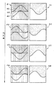
そして図7のF1、F2、F3、F4に示すように、ライン40のテクスチャ座標及びライン42のテクスチャ座標を時間経過に伴い変化させる。即ち、図7では、テクスチャ座標を変化させる第2の頂点群を複数グループ(ライン40のグループとライン42のグループ)設けている。このようにすることで、テクスチャの絵柄の境界44が、図7のG1、G2、G3、G4に示すように時間経過に伴い変化するように見え、画像のゆがみのリアルな表現が可能になる。
【0064】
なお図7では、テクスチャ座標を変化させるラインが40、42というように2本あるが(第2の頂点群が2グループあるが)、図8に示すように1本にしてもよい(第2の頂点群を1グループにしてもよい)。またテクスチャ座標を変化させるラインを3本以上にしてもよい(第2の頂点群を3グループ以上設けてもよい)。テクスチャ座標を変化させるラインを2本以上にすれば、表現できる画像のバリエーションを増すことができる。
【0065】
また図7に示すように、ライン40、42のテクスチャ座標は、周期関数(例えばサイン関数)により得ることが望ましい。このような周期関数を利用してテクスチャ座標を得れば、テクスチャ座標を変化させる処理の簡易化を図れる。
【0066】
そして、この場合、周期関数の波形や位相や周期を周期関数間で互いに異ならせることが望ましい。
【0067】
例えば図9では、ライン40のテクスチャ座標を得るための第1の周期関数の波形とライン42のテクスチャ座標を得るための第2の周期関数の波形とが、互いに異なっている。このようにすることで、図9のH1、H2、H3、H4に示すように、ゆがみの度合いがより激しい画像を表現できるようになる。
【0068】
また図10(A)では、ライン40のテクスチャ座標を得るための第1の周期関数の位相と、ライン42のテクスチャ座標を得るための第2の周期関数の位相とが、互いに異なっている。また図10(B)では、ライン40のテクスチャ座標を得るための第1の周期関数の周期と、ライン42のテクスチャ座標を得るための第2の周期関数の周期とが互いに異なっている。
【0069】
このように第1、第2の周期関数の波形や位相や周期を互いに異ならせれば、1つのテクスチャを用いて、様々な画像のゆがみを表現できる。即ち、少ないデータ量で、画像表現のバリエーションを豊かにすることが可能になる。
【0070】
さて、テクスチャ座標を時間経過に伴い局所的に変化させる手法としては、テクスチャ座標を時間経過に伴いリアルタイムに変更する手法と、テクスチャ座標が局所的に異なる複数のオブジェクトを時間経過に伴い順次差し替える手法とを考えることができる。この場合、表現される画像のバリエーションを増すためには、複数のオブジェクトを順次差し替える手法が望ましい。
【0071】
例えば波を表現するオブジェクトとして、図11に示すような複数の波オブジェクトを予め用意しておく。即ち、図2のオブジェクト情報記憶部144に、1つの波を表現するための複数の波オブジェクトのオブジェクト情報を記憶しておく。
【0072】
例えば図12に、これらの複数のオブジェクトのオブジェクト情報の例を示す。図12に示すように、各オブジェクトOB1、OB2、OB3の第1の頂点群VE1、VE2に与えられるテクスチャ座標(TX1、TY1)、(TX2、TY2)については、オブジェクトOB1、OB2、OB3間で互いに同一となっている。一方、第2の頂点群VE3、VE4に与えられるテクスチャ座標(TX3、TY3)、(TX4、TY4)については、オブジェクトOB1、OB2、OB3間で互いに異なっている。
【0073】
このようなOB1、OB2、OB3等を、時間経過に伴い順次差し替えれば、テクスチャ座標を時間経過に伴い局所的に変化させることができる。
【0074】
しかも、この時に、時間経過に伴い順次差し替えられる複数のオブジェクトの形状を、図11に示すように互いに異なる形状にすることで、テクスチャ座標の局所的変化により生じるゆがみ以上の映像効果を得ることができる。
【0075】
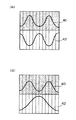
図13(A)に、テクスチャ座標を局所的に変化させずに、オブジェクトの差し替えのみを行った場合(オブジェクトの形状のみを変化させた場合)の例を示す。また図13(B)に、テクスチャ座標を局所的に変化させると共に、オブジェクトの差し替えも行った場合(オブジェクトの形状も変化させた場合)の例を示す。図13(B)のように、テクスチャ座標を局所的に変化させると共にオブジェクトの差し替えも行うことで、よりゆがんで見えるような画像表現が可能になる。これにより、図4(A)、(B)、(C)に示すように、よりリアルな波32の表現が可能になる。また図13(A)のようにオブジェクトの差し替えのみを行った場合に必要なデータ量(オブジェクト情報のデータ量)と、図13(B)のようにテクスチャ座標の局所的変化とオブジェクトの差し替えの両方を行った場合に必要なデータ量とは、同一になる。即ち、図13(B)の手法によれば、必要なデータ量を増すことなく、画像のゆがみのリアル度を増すことが可能になる。
【0076】
本実施形態の第2の特徴は、ボート(移動体)に随伴する波オブジェクト(広義には随伴オブジェクト)の形状を制御するための制御点を、ボートの速度が大きいほど、或いは水面(広義には高さが変化する所与の面)へのボートの沈み込み深さが深いほど、大きな初期速度で移動させると共に重力加速度(広義には所与の加速度)で減速させ、この制御点に基づいて、波オブジェクトの形状を制御する点にある。
【0077】
例えば図14(A)に示すように、ボート30の速度VBが大きい場合には、制御点CPは、大きな初期速度VCでY軸方向(上方)に移動する。そして、その後、重力加速度GAにより徐々に減速する。一方、ボート30の速度VBが小さい場合には、制御点CPは、小さな初期速度VCでY軸方向に移動し、その後、重力加速度GAにより徐々に減速する。この制御点CPの例えばY座標等に基づいて、評価点50付近に生じる波オブジェクト(図4(A)、(B)、(C)の波32を参照)の形状を制御すれば、ボート30の速度VBを、波オブジェクトの形状に反映させることができる。例えば制御点CPのY座標が大きいほど波オブジェクトの形状をY軸方向に大きくスケーリングすれば、ボート30の速度VBが大きいほど波が高くなるという現象をシミュレーションできるようになる。
【0078】
また図14(B)に示すように、波が生じるポイントを決める評価点50でのボート30の沈み込み深さ(喫水)DWが深い場合には、制御点CPは、大きな初期速度VCでY軸方向に移動し、その後、重力加速度GAにより徐々に減速する。一方、評価点50でのDWが浅い場合には、制御点CPは、小さな初期速度VCでY軸方向に移動し、その後、重力加速度GAにより徐々に減速する。この制御点CPの例えばY座標等に基づいて、評価点50付近に生じる波オブジェクトの形状を制御すれば、ボート30の沈み込み深さDWを、波オブジェクトの形状に反映させることができる。例えば制御点CPのY座標が大きいほど波オブジェクトの形状をY軸方向に大きくスケーリングすれば、ボート30の沈み込み深さDWが深いほど波が高くなるという現象をシミュレーションできるようになる。
【0079】
より具体的には本実施形態では以下に説明するような処理を行っている。
【0080】
即ち図15(A)、(B)、(C)、(D)、(E)に示すように、時間経過に伴い制御点CP1、CP2、CP3、CP4、CP5等を、ボート30の速度VBと沈み込み深さDWとにより決められる初期速度で順次Y軸方向に移動させ、順次移動した複数の制御点の中で初期位置から最もY座標の大きい制御点の位置に基づいて、波オブジェクトの形状を制御する。
【0081】
例えば図15(A)では、制御点CP1が、例えば位置(初期位置)YC=0.2から速度(初期速度)VC=6.5でY軸方向に移動する。この場合に、CP1のVCは、その時のボート30の速度VB、沈み込み深さDWに基づき決められる。即ち、例えばVC=C1×(C2×VB2+C3×DW2)1/2というような計算式(C1、C2、C3は定数)によりVCが決められる。そして、このCP1のYC及びVCは、制御点リスト52に登録される。
【0082】
また図15(B)では、制御点CP2が、例えばYC=−0.2からVC=4.0でY軸方向に移動し、このCP2のYC及びVCが制御点リスト52に登録される。またCP1のYC及びVCが重力加速度に基づいて計算され、制御点リスト52におけるCP1の登録内容が更新される。
【0083】
また図15(C)では、制御点CP3が、例えばYC=0.5からVC=5.0でY軸方向に移動し、このCP3のYC及びVCが制御点リスト52に登録される。またCP1、CP2のYC及びVCが重力加速度に基づいて計算され、制御点リスト52におけるCP1、CP2の登録内容が更新される。
【0084】
また図15(D)では、制御点CP4が、例えばYC=−0.3からVC=3.5でY軸方向に移動し、このCP4のYC及びVCが制御点リスト52に登録される。またCP1、CP2、CP3のYC及びVCが重力加速度に基づいて計算され、制御点リスト52におけるCP1、CP2、CP3の登録内容が更新される。
【0085】
また図15(E)では、制御点CP5が、例えばYC=0.2からVC=7.0でY軸方向に移動し、このCP5のYC及びVCが制御点リスト52に登録される。また、CP1のYCが0以下になったため、CP1の登録が制御点リスト52から削除される。またCP2、CP3、CP4のYC及びVCが重力加速度に基づいて計算され、制御点リスト52におけるCP2、CP3、CP4の登録内容が更新される。
【0086】
波オブジェクトの形状は、複数の制御点の中で最もY座標が大きい制御点のY座標に基づいて制御される。例えば図15(C)では、CP1のY座標であるYC=7.0に基づいて波オブジェクトの形状が制御される。また図15(D)では、CP2のYC=4.5に基づいて波オブジェクトの形状が制御され、図15(E)では、CP3のYC=6.0に基づいて波オブジェクトの形状が制御される。
【0087】
本実施形態では、波オブジェクトの形状の制御を、例えば図16に示すように、波オブジェクトのY軸方向のスケーリング値を変化させることで実現している。そして、例えば制御点のY座標が大きいほど、波オブジェクトのY軸方向のスケーリング値を大きくする。この場合、図14(A)、(B)で説明したように、制御点のY座標は、ボート30の速度VBが大きいほど大きくなると共にボート30の沈み込み深さDWが深いほど大きくなる。従って、結局、VBが大きいほど或いはDWが深いほど、波オブジェクトのY軸方向のスケーリング値が大きくなる。これにより、ボートの速度が大きいほど或いは沈み込み深さが深いほど波が高くなるという現象をリアルにシミュレーションできるようになる。
【0088】
例えば波の高さの変化のシミュレーションを、現実世界の現象に忠実な物理計算により実現しようとすると、その計算負荷は膨大なものとなってしまう。
【0089】
これに対して本実施形態では、波の高さを制御する制御点という概念を導入することで、少ない計算負荷で、波の高さの変化のリアルなシミュレーションを実現することに成功している。即ち本実施形態によれば、VB、DWに基づいて決められる初期速度VCで制御点を順次Y軸方向に移動させ、その制御点のY座標に基づいて波オブジェクトのY軸方向のスケーリング値を変化させるという負荷の少ない簡易な処理で、波の高さの変化のリアルなシミュレーションを実現できる。
【0090】
3.本実施形態の処理
次に、本実施形態の詳細な処理例について図17、図18のフローチャートを用いて説明する。
【0091】
図17は、オブジェクトの差し替えによりテクスチャ座標の局所的変化を実現する処理に関するフローチャートである。
【0092】
まず、図11に示すような複数の波オブジェクトの中から、当該フレームで使用する波オブジェクトを選択する(ステップS1)。次に、選択した波オブジェクトのオブジェクト情報(図12参照)を、オブジェクト情報記憶部144(図2参照)から読み出す(ステップS2)。
【0093】
次に、波の高さをサンプリングするフレーム(新規の制御点を制御点リストに登録するフレーム)か否かを判断する(ステップS3)。本実施形態では、1フレーム毎ではなく数フレーム毎(例えば3〜10フレーム毎)に波の高さをサンプリングする。そして、波の高さをサンプリングするフレームである場合には、図14(A)、(B)、図15(A)〜(E)で説明したように、制御点の初期位置と初期速度を、ボートの速度と沈み込み深さとに基づいて決定し、その制御点を制御点リストに登録する(ステップS4)。
【0094】
次に、制御点リストに登録された制御点のY座標を、重力加速度と各制御点の速度に基づいて演算する(ステップS5)。即ち初期速度でY軸方向に移動した制御点を、重力加速度により徐々に減速させる。
【0095】
次に、Y座標が0以下となった制御点を制御点リストから削除する(ステップS6)。例えば図15(E)では、制御点CP1が制御点リスト52から削除される。
【0096】
次に、制御点リスト内で最もY座標が大きい制御点のY座標に基づいて、波オブジェクトのスケーリング値(図16参照)を得る(ステップS7)。
【0097】
次に、ステップS2で読み出されたオブジェクト情報に含まれるテクスチャ座標に基づいて、図5〜図10(B)で説明したようにテクスチャをマッピングすると共に、ステップS7で得られたスケーリング値に基づいて波オブジェクトをスケーリングする(ステップS8)。
【0098】
図18は、オブジェクトのテクスチャ座標をリアルタイムに変更することによりテクスチャ座標の局所的変化を実現する処理に関するフローチャートである。
【0099】
まず波オブジェクトのオブジェクト情報を、オブジェクト情報記憶部144(図2参照)から読み出す(ステップU1)。次に、読み出されたオブジェクト情報に含まれるテクスチャ座標を局所的に変更する(ステップU2)。この変更処理は、図2のテクスチャ座標変更部118が行う。
【0100】
次に図17のステップS3〜S7と同様の処理を行い、波オブジェクトのスケーリング値を得る(ステップU3〜U7)。
【0101】
次に、ステップU2で変更されたテクスチャ座標に基づいてテクスチャをマッピングすると共に、ステップU7で得られたスケーリング値に基づいて波オブジェクトをスケーリングする(ステップU8)。
【0102】
以上の図17或いは図18に示す処理を行うことで、図4(A)、(B)、(C)に示すような波32のリアルな表現が可能になる。
【0103】
なお本発明は、上記実施形態で説明したものに限らず、種々の変形実施が可能である。
【0104】
例えばテクスチャ座標の局所的変化は、オブジェクトを差し替える手法や、テクスチャ座標をリアルタイムに変更する手法により実現することが特に望ましいが、本発明では、これらとは異なる手法で実現するようにしてもよい。
【0105】
また、局所的に変化させるテクスチャ座標は、図7〜図10(B)のように周期関数に基づき得ることが特に望ましいが、本発明は、これに限定されるものではない。例えば周期関数ではない関数によりテクスチャ座標を得るようにしもよい。
【0106】
また本実施形態では、波オブジェクトへのテクスチャマッピングを例にとり説明したが、本発明はこれに限定されず、波オブジェクト以外の種々のオブジェクトへのテクスチャマッピングに適用できる。例えば本発明は、弾の発射時や爆弾の爆発時などに生じる爆発(せん光)オブジェクトへのテクスチャマッピングにも適用できる。また表示物のきらめきや、液体が流れる様子や、海岸へうち寄せる波などの表現にも本発明は適用できる。
【0107】
また制御点の初期速度は、移動体の速度及び沈み込み深さの両方により決めるようにしてもよいし、いずれか一方により決めるようにしてもよい。
【0108】
また本実施形態では、移動体が水面を走行する場合を例にとり説明したが、高さが変化する所与の面は、このような水面に限定されない。例えば、このような所与の面としては、車が砂漠を走行する場合の砂地面などを考えることができる。この場合は随伴オブジェクトは例えば砂埃のオブジェクトになる。
【0109】
また本実施形態では、随伴オブジェクトをY軸方向(上方向)にスケーリングする場合について説明したが、随伴オブジェクトをスケーリングする方向はY軸方向に限定されない。また随伴オブジェクトの形状の制御は、所与の方向へのスケーリングに限定されず、例えばオブジェクトの差し替えなどにより形状を制御してもよい。
【0110】
また本発明は釣りゲーム以外にも種々のゲーム(車レースゲームやバイクゲームやスキーゲームなどの競争ゲーム、格闘ゲーム、ロボット対戦ゲーム、野球やサッカーなどのスポーツゲーム、ガンゲームなどのシューティングゲーム、音楽演奏ゲーム、ダンスゲーム、ロールプレイングゲーム、クイズゲーム、パズルゲーム等)に適用できる。
【0111】
また本発明は、業務用ゲーム装置、家庭用ゲーム装置、多数のプレーヤが参加する大型アトラクション装置、シミュレータ、マルチメディア端末、画像生成装置、ゲーム画像を生成するシステム基板等の種々のゲーム装置に適用できる。
【0112】
【図面の簡単な説明】
【図1】本実施形態のゲーム装置の外観図の例である。
【図2】本実施形態のゲーム装置のブロック図の例である。
【図3】図3(A)、(B)は、本実施形態により生成されるゲーム画像の例を示す図である。
【図4】図4(A)、(B)、(C)も、本実施形態により生成されるゲーム画像の例を示す図である。
【図5】テクスチャ座標を局所的に変化させる手法について説明するための図である。
【図6】オブジェクトにマッピングするテクスチャと、マッピング対象となるオブジェクトの例について示す図である。
【図7】テクスチャ座標が変化するラインを2本設けた場合の例について説明するための図である。
【図8】テクスチャ座標が変化するラインを1本設けた場合の例について説明するための図である。
【図9】ラインのテクスチャ座標を変化させる第1、第2の周期関数の波形を互いに異ならせる手法について説明するための図である。
【図10】図10(A)、(B)は、ラインのテクスチャ座標を変化させる第1、第2の周期関数の位相や周期を互いに異ならせる手法について説明するための図である。
【図11】時間経過に伴い差し替えられる複数の波オブジェクトの例を示す図である。
【図12】オブジェクト情報の例を示す図である。
【図13】図13(A)は、オブジェクトの差し替えのみを行う手法について説明するための図であり、図13(B)は、テクスチャ座標の局所変化とオブジェクトの差し替えの両方を行う手法について説明するための図である。
【図14】図14(A)、(B)は、ボートの速度や沈み込み深さに応じた初期速度で制御点を移動させると共に重力加速度で制御点を減速させる手法について説明するための図である。
【図15】図15(A)、(B)、(C)、(D)、(E)は、制御点を順次移動させ、複数の制御点の中で最もY座標が大きい制御点のY座標に基づいて、波オブジェクトの形状を制御する手法について説明するための図である。
【図16】波オブジェクトのY軸方向でのスケーリングについて説明するための図である。
【図17】本実施形態の詳細な処理例を示すフローチャートの一例である。
【図18】本実施形態の詳細な処理例を示すフローチャートの一例である。
【符号の説明】
20 仮想プレーヤ
22 キャストエリア
30 ボート(移動体)
32 波
40、42 ライン
44 テクスチャの絵柄の境界
50 評価点
52 制御点リスト
100 処理部
110 ゲーム演算部
112 移動体演算部
114 マッピング処理部
116 オブジェクト差し替え部
118 テクスチャ座標変更部
120 制御点処理部
122 オブジェクト形状制御部
130 操作部
140 記憶部
142 テクスチャ情報記憶部
144 オブジェクト情報記憶部
150 情報記憶媒体
160 画像生成部
162 表示部
170 音生成部
172 音出力部
174 通信部
176 I/F部
180 メモリーカード(又はPDA)
800 ハウジング
802 アーム
804 ロッド
806 リール
808 操作ボタン
810 画面
812 魚
814 ルアー
816 ライン
820 スロット[0001]
BACKGROUND OF THE INVENTION
The present invention relates to a game device and an information storage medium.
[0002]
[Background Art and Problems to be Solved by the Invention]
2. Description of the Related Art Conventionally, a game apparatus that arranges a plurality of objects in an object space that is a virtual three-dimensional space and generates an image that can be seen from a given viewpoint in the object space is known, and a so-called virtual reality can be experienced. Popular as a thing. Taking a game device that can enjoy a competitive game by boat as an example, a player runs a boat operated by himself / herself on a course in the object space and competes with a boat operated by another player or a computer. Enjoy.
[0003]
However, conventional game devices have not been able to realize a realistic expression of waves generated as the boat travels. In other words, the wave object whose shape and pattern do not change is simply accompanied by the boat, and the displayed image is monotonous. For this reason, the virtual reality that the player feels cannot be improved.
[0004]
Further, a technique called texture mapping has been conventionally known as a technique for improving the quality of game images. In this texture mapping, the texture (texture information) is read from the texture information storage unit based on the texture coordinates given to the vertex of the object, and the read texture is mapped to the object. According to this texture mapping, a high quality image can be obtained with a small amount of data.
[0005]
However, in the texture mapping so far, the texture coordinates (UV coordinates) for designating the texture are fixed values and do not change. For this reason, the variety of the image cannot be increased.
[0006]
The present invention has been made to solve the above-described problems, and an object of the present invention is to provide a game device and an information storage medium capable of realizing an unprecedented image expression using texture mapping. There is to do.
[0007]
Another object of the present invention is to provide a game apparatus and an information storage medium that enable realistic expression of an object accompanying a moving body moving on a given plane.
[0008]
[Means for Solving the Problems]
In order to solve the above-described problems, the present invention provides a game apparatus for generating an image, a means for storing texture information specified by texture coordinates given to each vertex of an object, Using the first texture coordinates that are given to the first vertex group and that do not change with time, and the second texture coordinates that are given to the second vertex group of the object and change with time, the texture is applied to the object. And means for performing a process of mapping.
[0009]
The information storage medium according to the present invention includes information for realizing the above means.
[0010]
According to the present invention, the first texture coordinates of the first vertex group (which may have one vertex) of the object do not change with time, and the second vertex group (which may have one vertex) does not change. The second texture coordinates change with time. As a result, it is possible to make an expression as if the texture image looks distorted, and it is possible to increase variations of the image that is expressed while using one texture.
[0011]
The game device and the information storage medium according to the present invention are characterized in that the second texture coordinates are changed in real time as time passes. In this way, it becomes possible to change the distortion of the image in real time according to the game situation or the like.
[0012]
The present invention is also a game device for generating an image, comprising means for storing texture information specified by texture coordinates given to each vertex of an object, and a first vertex group of each object. Means for storing object information of a plurality of objects, wherein the given first texture coordinates are the same among the objects and the second texture coordinates given to the second vertex group are different among the objects; Means for performing a process of mapping a texture to an object using texture coordinates included in information, and means for performing a process of sequentially replacing the plurality of objects with the passage of time in order to represent one display object It is characterized by including.
[0013]
The information storage medium according to the present invention includes information for realizing the above means.
[0014]
According to the present invention, the objects for representing the display object are sequentially replaced with time, for example, from the first object to the second object and from the second object to the third object. For example, between the first and second objects, the first texture coordinates of the first vertex group are the same, but the second texture coordinates of the second vertex group are different. Therefore, by replacing the first object with the second object, the texture coordinates can be locally changed, and image distortion and the like can be expressed.
[0015]
The game device and the information storage medium according to the present invention are characterized in that the shapes of the plurality of objects that are sequentially replaced with the passage of time are different from each other. In this way, it becomes possible to express distortion more than image distortion due to local changes in texture coordinates. In the present invention, an object having the same shape may be included in a plurality of objects.
[0016]
The game device and information storage medium according to the present invention are characterized in that the texture coordinates of the second vertex group are obtained by a periodic function. If texture coordinates are obtained using a periodic function in this way, processing such as changing texture coordinates can be simplified.
[0017]
The game device and the information storage medium according to the present invention are characterized in that the second vertex group includes a plurality of groups. In this way, it is possible to change the texture coordinates at one second vertex group so as to be different from the changes in the texture coordinates at the other second vertex group. Thereby, the variation of the image represented can be increased.
[0018]
In the game device and the information storage medium according to the present invention, the texture coordinates of each second vertex group can be obtained by each periodic function, and at least one of the waveform, phase, and period of each periodic function differs between the periodic functions. It is characterized by that. In this way, by varying the waveform, phase, and period between periodic functions, it is possible to express various distortion images while using one texture.
[0019]
Further, the present invention is a game apparatus for generating an image, for controlling movement information of a moving body that moves in an object space, and for controlling a shape of an accompanying object that accompanies the moving body. In order to control the shape of the accompanying object based on the means for moving the control point at a larger initial speed as the speed of the moving body is increased and decelerating at a given acceleration, and the control point Means.
[0020]
The information storage medium according to the present invention includes information for realizing the above means.
[0021]
According to the present invention, the shape of the accompanying object of the moving body is controlled based on the control point that moves at an initial speed corresponding to the speed of the moving body and decelerates at a given acceleration. In this way, the speed of the moving object can be reflected in the shape of the accompanying object, and a more realistic simulation of the shape change of the accompanying object can be realized.
[0022]
In addition, the present invention is a game device for generating an image for calculating movement information of a moving body that moves in an object space while sinking a part of a given surface whose height changes. And a control point for controlling the shape of the accompanying object accompanying the moving object at a higher initial speed as the moving object sinks deeper into the given plane. The apparatus includes means for performing a process of decelerating by acceleration, and means for controlling the shape of the accompanying object based on the control point.
[0023]
The information storage medium according to the present invention includes information for realizing the above means.
[0024]
According to the present invention, the shape of the accompanying object of the moving object is controlled based on the control point that moves at an initial speed corresponding to the submerged depth of the moving object and decelerates at a given acceleration. In this way, the sinking depth of the moving object can be reflected in the shape of the accompanying object, and a more realistic simulation of the shape change of the accompanying object can be realized.
[0025]
In addition, the game device and the information storage medium according to the present invention sequentially move the control point at the initial speed as time passes, and the position of the control point moved farthest from the initial position among the plurality of sequentially moved control points. Based on the above, the shape of the accompanying object is controlled. In this way, a realistic change in the shape of the accompanying object over time can be realized with simple processing.
[0026]
In addition, the game device and the information storage medium according to the present invention control the shape of the accompanying object by scaling the accompanying object in a given direction. In this way, the shape of the accompanying object can be controlled by a process with a small burden.
[0027]
DETAILED DESCRIPTION OF THE INVENTION
Hereinafter, preferred embodiments of the present invention will be described with reference to the drawings. In the following, the case where the present invention is applied to a fishing game will be described as an example. However, the present invention is not limited to this and can be applied to various games. In the following description, the case where one or a plurality of primitive surfaces constituting an object is a polygon will be described as an example. However, the present invention is not limited to this, and the object is configured by a primitive surface other than a polygon (for example, a curved surface). It can also be applied to
[0028]
1. Constitution
FIG. 1 shows an example of an external view of the game apparatus according to the present embodiment.
[0029]
This game apparatus has an
[0030]
This game device is provided with a
[0031]
When the fishing game starts, the player first performs casting. Then, the
[0032]
When the player picks up the
[0033]
FIG. 2 shows an example of a block diagram of the present embodiment.
[0034]
Here, the
[0035]
The
[0036]
The
[0037]
An information storage medium (storage medium from which information can be read by a computer) 150 stores information such as programs and data, and functions thereof are an optical disk (CD, DVD), a magneto-optical disk (MO), and a magnetic field. This can be realized by hardware such as a disk, a hard disk, a magnetic tape, and a semiconductor memory (ROM). The
[0038]
Part or all of the information stored in the
[0039]
The
[0040]
The
[0041]
The
[0042]
Information for realizing the processing of the present invention (this embodiment) may be distributed from the information storage medium of the host device to the information storage medium of the game device via the network and the
[0043]
Further, some or all of the functions of the
[0044]
The I /
[0045]
The
[0046]
Here, the
[0047]
The
[0048]
Here, the moving
[0049]
More specifically, the moving
[0050]
PMk = PMk-1 + VMk-1 * .DELTA.t (1)
VMk = VMk-1 + AMk-1 * .DELTA.t (2)
The
[0051]
Note that texture information to be mapped is stored in the texture
[0052]
The object replacement unit 116 performs processing for sequentially replacing a plurality of objects with the passage of time in order to express one display object. More specifically, a process of sequentially replacing the wave objects for expressing the waves generated as the boat travels as time passes is performed. Here, it is desirable that the shapes of the objects that are sequentially replaced as time elapses are different from each other.
[0053]
Note that information on the object to be replaced is stored in the object
[0054]
The texture coordinate changing
[0055]
The control
[0056]
2. Features of this embodiment
3A, 3B, 4A, 4B, and 4C show examples of game images generated by the present embodiment.
[0057]
When the game is started, as shown in FIG. 3A, a
[0058]
Now, when the boat (moving body) 30 goes to the
[0059]
The first feature of the present embodiment is that the texture coordinates given to each vertex of an object (configured by one or more primitive surfaces) are locally changed to represent image distortion. .
[0060]
More specifically, as shown in FIG. 5, with respect to the texture coordinates (TX1, TY1), (TX2, TY2) given to the first vertex group VE1, VE2 of the object OB, the value is changed with time. Do not change. On the other hand, the values of the texture coordinates (TX3, TY3), (TX4, TY4) given to the second vertex group VE3, VE4 of the object OB are changed with time. In this way, the distortion of the image of the object OB can be expressed using a single texture. That is, image variations can be increased without increasing the used storage capacity of the texture
[0061]
The distortion of the image mapped to the
[0062]
That is, first, for example, a texture as shown by E1 in FIG. 6 is prepared. The texture here is mapped to an object composed of a plurality of polygons PG1 to PG36 as shown by E2.
[0063]
Then, as indicated by F1, F2, F3, and F4 in FIG. 7, the texture coordinates of the
[0064]
In FIG. 7, there are two
[0065]
Further, as shown in FIG. 7, it is desirable to obtain the texture coordinates of the
[0066]
In this case, it is desirable to vary the waveform, phase, and period of the periodic function between the periodic functions.
[0067]
For example, in FIG. 9, the waveform of the first periodic function for obtaining the texture coordinates of the
[0068]
In FIG. 10A, the phase of the first periodic function for obtaining the texture coordinates of the
[0069]
In this way, if the waveforms, phases, and periods of the first and second periodic functions are different from each other, various image distortions can be expressed using one texture. That is, it is possible to enrich image expression variations with a small amount of data.
[0070]
Now, as a technique to change texture coordinates locally with the passage of time, a technique of changing texture coordinates in real time with the passage of time and a technique of sequentially replacing a plurality of objects having different texture coordinates with the passage of time. Can be considered. In this case, in order to increase the variation of the image to be expressed, a method of sequentially replacing a plurality of objects is desirable.
[0071]
For example, a plurality of wave objects as shown in FIG. 11 are prepared in advance as objects representing waves. That is, object information of a plurality of wave objects for expressing one wave is stored in the object
[0072]
For example, FIG. 12 shows an example of object information of these plural objects. As shown in FIG. 12, the texture coordinates (TX1, TY1), (TX2, TY2) given to the first vertex group VE1, VE2 of each object OB1, OB2, OB3 are between the objects OB1, OB2, OB3. They are identical to each other. On the other hand, the texture coordinates (TX3, TY3), (TX4, TY4) given to the second vertex groups VE3, VE4 are different from each other among the objects OB1, OB2, OB3.
[0073]
If such OB1, OB2, OB3, and the like are sequentially replaced with the passage of time, the texture coordinates can be locally changed with the passage of time.
[0074]
Moreover, at this time, by making the shapes of the plurality of objects that are sequentially replaced with the passage of time different from each other as shown in FIG. 11, it is possible to obtain a video effect that is more than the distortion caused by the local change of the texture coordinates. it can.
[0075]
FIG. 13A shows an example in which only replacement of an object is performed without changing texture coordinates locally (when only the shape of the object is changed). FIG. 13B shows an example in which the texture coordinates are locally changed and the object is replaced (the object shape is also changed). As shown in FIG. 13B, by changing the texture coordinates locally and also replacing the objects, it is possible to display an image that looks more distorted. As a result, as shown in FIGS. 4A, 4B, and 4C, a more
[0076]
The second feature of the present embodiment is that a control point for controlling the shape of a wave object (accompanied object in a broad sense) associated with a boat (moving body) is increased as the speed of the boat increases or the water surface (in a broad sense). Based on this control point, the deeper the boat sinks into the given plane where the height changes, the greater the initial speed and the lower the gravitational acceleration (the given acceleration in a broad sense). The point is to control the shape of the wave object.
[0077]
For example, as shown in FIG. 14A, when the speed VB of the
[0078]
Further, as shown in FIG. 14B, when the submergence depth (draft) DW of the
[0079]
More specifically, in the present embodiment, processing as described below is performed.
[0080]
That is, as shown in FIGS. 15 (A), (B), (C), (D), and (E), the control points CP1, CP2, CP3, CP4, CP5, etc. are changed with the speed VB of the
[0081]
For example, in FIG. 15A, the control point CP1 moves in the Y-axis direction at a speed (initial speed) VC = 6.5 from a position (initial position) YC = 0.2, for example. In this case, the VC of CP1 is determined based on the speed VB of the
[0082]
In FIG. 15B, the control point CP2 moves in the Y-axis direction, for example, from YC = −0.2 to VC = 4.0, and the YC and VC of this CP2 are registered in the
[0083]
In FIG. 15C, the control point CP3 moves in the Y-axis direction, for example, from YC = 0.5 to VC = 5.0, and the YC and VC of this CP3 are registered in the
[0084]
In FIG. 15D, the control point CP4 moves in the Y-axis direction, for example, from YC = −0.3 to VC = 3.5, and the YC and VC of this CP4 are registered in the
[0085]
In FIG. 15E, the control point CP5 moves in the Y-axis direction, for example, from YC = 0.2 to VC = 7.0, and YC and VC of this CP5 are registered in the
[0086]
The shape of the wave object is controlled based on the Y coordinate of the control point having the largest Y coordinate among the plurality of control points. For example, in FIG. 15C, the shape of the wave object is controlled based on YC = 7.0, which is the Y coordinate of CP1. In FIG. 15D, the shape of the wave object is controlled based on YC = 4.5 of CP2, and in FIG. 15E, the shape of the wave object is controlled based on YC = 6.0 of CP3. The
[0087]
In the present embodiment, the control of the shape of the wave object is realized by changing the scaling value in the Y-axis direction of the wave object, for example, as shown in FIG. For example, the larger the Y coordinate of the control point, the larger the scaling value in the Y axis direction of the wave object. In this case, as described with reference to FIGS. 14A and 14B, the Y coordinate of the control point increases as the speed VB of the
[0088]
For example, if the simulation of the change in wave height is to be realized by physical calculation faithful to the real world phenomenon, the calculation load becomes enormous.
[0089]
On the other hand, in this embodiment, by introducing the concept of a control point that controls the wave height, it has succeeded in realizing a realistic simulation of changes in wave height with a small calculation load. . That is, according to the present embodiment, the control point is sequentially moved in the Y-axis direction at the initial speed VC determined based on VB and DW, and the scaling value of the wave object in the Y-axis direction is determined based on the Y coordinate of the control point. Realistic simulation of changes in wave height can be realized with simple processing with little load.
[0090]
3. Processing of this embodiment
Next, a detailed processing example of the present embodiment will be described with reference to the flowcharts of FIGS.
[0091]
FIG. 17 is a flowchart regarding processing for realizing a local change in texture coordinates by replacing an object.
[0092]
First, a wave object used in the frame is selected from a plurality of wave objects as shown in FIG. 11 (step S1). Next, the object information (see FIG. 12) of the selected wave object is read from the object information storage unit 144 (see FIG. 2) (step S2).
[0093]
Next, it is determined whether or not it is a frame for sampling the wave height (frame for registering a new control point in the control point list) (step S3). In the present embodiment, the wave height is sampled not every frame but every several frames (for example, every 3 to 10 frames). In the case of a frame for sampling the wave height, the initial position and initial velocity of the control point are set as described with reference to FIGS. 14 (A), (B), and FIGS. 15 (A) to (E). The determination is made based on the boat speed and the subduction depth, and the control point is registered in the control point list (step S4).
[0094]
Next, the Y coordinate of the control point registered in the control point list is calculated based on the gravitational acceleration and the speed of each control point (step S5). That is, the control point moved in the Y-axis direction at the initial speed is gradually decelerated by the gravitational acceleration.
[0095]
Next, the control point whose Y coordinate is 0 or less is deleted from the control point list (step S6). For example, in FIG. 15E, the control point CP1 is deleted from the
[0096]
Next, the scaling value (see FIG. 16) of the wave object is obtained based on the Y coordinate of the control point having the largest Y coordinate in the control point list (step S7).
[0097]
Next, based on the texture coordinates included in the object information read in step S2, the texture is mapped as described in FIGS. 5 to 10B, and based on the scaling value obtained in step S7. The wave object is scaled (step S8).
[0098]
FIG. 18 is a flowchart relating to processing for realizing a local change in texture coordinates by changing the texture coordinates of an object in real time.
[0099]
First, the object information of the wave object is read from the object information storage unit 144 (see FIG. 2) (step U1). Next, the texture coordinates included in the read object information are locally changed (step U2). This change process is performed by the texture coordinate changing
[0100]
Next, processing similar to steps S3 to S7 in FIG. 17 is performed to obtain a scaling value of the wave object (steps U3 to U7).
[0101]
Next, the texture is mapped based on the texture coordinates changed in step U2, and the wave object is scaled based on the scaling value obtained in step U7 (step U8).
[0102]
By performing the processing shown in FIG. 17 or FIG. 18, a realistic expression of the
[0103]
The present invention is not limited to that described in the above embodiment, and various modifications can be made.
[0104]
For example, the local change of the texture coordinate is particularly preferably realized by a method of replacing an object or a method of changing the texture coordinate in real time. However, in the present invention, it may be realized by a method different from these.
[0105]
In addition, it is particularly desirable that the texture coordinates to be locally changed are based on a periodic function as shown in FIGS. 7 to 10B, but the present invention is not limited to this. For example, the texture coordinates may be obtained by a function that is not a periodic function.
[0106]
In the present embodiment, the texture mapping to the wave object has been described as an example. However, the present invention is not limited to this and can be applied to the texture mapping to various objects other than the wave object. For example, the present invention can be applied to texture mapping to an explosion (flash) object that occurs when a bullet is fired or a bomb explodes. The present invention can also be applied to expressions such as sparkling display objects, liquid flowing, and waves approaching the beach.
[0107]
In addition, the initial speed of the control point may be determined by both the speed of the moving body and the sinking depth, or may be determined by either one.
[0108]
Further, in the present embodiment, the case where the moving body travels on the water surface has been described as an example, but a given surface whose height changes is not limited to such a water surface. For example, such a given surface can be a sandy surface when a vehicle travels in a desert. In this case, the accompanying object is, for example, a dust object.
[0109]
In this embodiment, the case where the accompanying object is scaled in the Y-axis direction (upward) has been described. However, the direction in which the accompanying object is scaled is not limited to the Y-axis direction. Control of the shape of the accompanying object is not limited to scaling in a given direction, and the shape may be controlled, for example, by replacing the object.
[0110]
In addition to fishing games, the present invention also provides various games (competition games such as car racing games, motorcycle games, and ski games, fighting games, robot battle games, sports games such as baseball and soccer, shooting games such as gun games, music, etc. It can be applied to performance games, dance games, role playing games, quiz games, puzzle games, and the like.
[0111]
The present invention is also applicable to various game devices such as a business game device, a home game device, a large attraction device in which a large number of players participate, a simulator, a multimedia terminal, an image generation device, and a system board for generating a game image. it can.
[0112]
[Brief description of the drawings]
FIG. 1 is an example of an external view of a game device according to an embodiment of the present invention.
FIG. 2 is an example of a block diagram of the game device according to the present embodiment.
FIGS. 3A and 3B are diagrams showing examples of game images generated according to the present embodiment.
FIGS. 4A, 4B, and 4C are diagrams showing examples of game images generated by the present embodiment. FIG.
FIG. 5 is a diagram for explaining a technique for locally changing texture coordinates;
FIG. 6 is a diagram illustrating an example of a texture to be mapped to an object and an object to be mapped.
FIG. 7 is a diagram for explaining an example in which two lines in which texture coordinates change are provided.
FIG. 8 is a diagram for explaining an example in which one line in which texture coordinates change is provided.
FIG. 9 is a diagram for explaining a method of making the waveforms of the first and second periodic functions for changing the texture coordinates of a line different from each other.
FIGS. 10A and 10B are diagrams for explaining a method of making the phases and periods of the first and second periodic functions for changing the texture coordinates of a line different from each other.
FIG. 11 is a diagram illustrating an example of a plurality of wave objects that are replaced as time elapses.
FIG. 12 is a diagram illustrating an example of object information.
FIG. 13A is a diagram for describing a technique for performing only object replacement, and FIG. 13B illustrates a technique for performing both local change of texture coordinates and object replacement. It is a figure for doing.
FIGS. 14A and 14B are diagrams for explaining a method of moving a control point at an initial speed according to the speed of the boat and the sinking depth, and decelerating the control point by gravitational acceleration. It is.
15 (A), (B), (C), (D), and (E) sequentially move the control points, and Y of the control point having the largest Y coordinate among a plurality of control points. It is a figure for demonstrating the method of controlling the shape of a wave object based on a coordinate.
FIG. 16 is a diagram for explaining scaling in the Y-axis direction of a wave object.
FIG. 17 is an example of a flowchart showing a detailed processing example of the present embodiment.
FIG. 18 is an example of a flowchart showing a detailed processing example of the present embodiment.
[Explanation of symbols]
20 Virtual player
22 Cast area
30 boat (moving body)
32 waves
40, 42 lines
44 Texture pattern border
50 evaluation points
52 Control point list
100 processor
110 Game calculation part
112 Mobile object calculation unit
114 Mapping processing unit
116 Object replacement part
118 Texture coordinate changing section
120 Control point processor
122 Object shape controller
130 Operation unit
140 Storage unit
142 Texture information storage unit
144 Object information storage unit
150 Information storage medium
160 Image generator
162 Display section
170 Sound generator
172 sound output unit
174 Communication Department
176 I / F section
180 Memory card (or PDA)
800 housing
802 Arm
804 rod
806 reel
808 operation buttons
810 screen
812 fish
814 Lure
816 lines
820 slots
Claims (16)
オブジェクトの各頂点に与えられるテクスチャ座標により指定されるテクスチャの情報を記憶するための手段と、
オブジェクトの第1の頂点群に与えられ時間経過に伴い変化しない第1のテクスチャ座標と、当該オブジェクトの第2の頂点群に与えられ時間経過に伴い変化する第2のテクスチャ座標とを用いて、当該オブジェクトにテクスチャをマッピングする処理を行うための手段とを含むことを特徴とするゲーム装置。A game device for generating an image,
Means for storing texture information specified by texture coordinates given to each vertex of the object;
Using the first texture coordinates that are given to the first vertex group of the object and that do not change with time, and the second texture coordinates that are given to the second vertex group of the object and change with time, game apparatus characterized by comprising a means for performing a process of mapping the texture to the object.
前記第2のテクスチャ座標を時間経過に伴いリアルタイムに変更することを特徴とするゲーム装置。In claim 1,
The game apparatus, wherein the second texture coordinates are changed in real time with the passage of time.
オブジェクトの各頂点に与えられるテクスチャ座標により指定されるテクスチャの情報を記憶するための手段と、
各オブジェクトの第1の頂点群に与えられる第1のテクスチャ座標がオブジェクト間で互いに同一であり第2の頂点群に与えられる第2のテクスチャ座標がオブジェクト間で互いに異なる複数のオブジェクトのオブジェクト情報を記憶するための手段と、
前記オブジェクト情報に含まれるテクスチャ座標を用いて、オブジェクトにテクスチャをマッピングする処理を行うための手段と、
1つの表示物を表現するために前記複数のオブジェクトを時間経過に伴い順次差し替える処理を行うための手段とを含むことを特徴とするゲーム装置。A game device for generating an image,
Means for storing texture information specified by texture coordinates given to each vertex of the object;
Object information of a plurality of objects in which the first texture coordinates given to the first vertex group of each object are the same among the objects and the second texture coordinates given to the second vertex group are different from each other between the objects. Means for memorizing;
Means for performing a process of mapping a texture to an object using a texture coordinate included in the object information;
A game apparatus comprising: means for performing a process of sequentially replacing the plurality of objects with the passage of time in order to represent one display object.
時間経過に伴い順次差し替えられる前記複数のオブジェクトの形状が、互いに異なることを特徴とするゲーム装置。In claim 3,
A game device characterized in that shapes of the plurality of objects that are sequentially replaced with time are different from each other.
前記第2の頂点群のテクスチャ座標が、周期関数により得られることを特徴とするゲーム装置。In any one of Claims 1 thru | or 4,
The game apparatus, wherein the texture coordinates of the second vertex group are obtained by a periodic function.
前記第2の頂点群が複数グループあることを特徴とするゲーム装置。In any one of Claims 1 thru | or 5,
A game apparatus comprising a plurality of the second vertex groups.
各第2の頂点群のテクスチャ座標が各周期関数により得られると共に、
各周期関数の波形、位相及び周期の少なくとも1つが周期関数間で互いに異なることを特徴とするゲーム装置。In claim 6,
The texture coordinates of each second vertex group are obtained by each periodic function,
A game apparatus, wherein at least one of a waveform, a phase, and a period of each periodic function is different between the periodic functions.
オブジェクトの各頂点に与えられるテクスチャ座標により指定されるテクスチャの情報を記憶するための手段と、
オブジェクトの第1の頂点群に与えられ時間経過に伴い変化しない第1のテクスチャ座標と、当該オブジェクトの第2の頂点群に与えられ時間経過に伴い変化する第2のテクスチャ座標とを用いて、当該オブジェクトにテクスチャをマッピングする処理を行うための手段と、
として機能させるためのプログラムを記憶したことを特徴とする情報記憶媒体。Computer
Means for storing texture information specified by texture coordinates given to each vertex of the object;
Using the first texture coordinates that are given to the first vertex group of the object and that do not change with time, and the second texture coordinates that are given to the second vertex group of the object and change with time, and means for processing for mapping a texture to the object,
An information storage medium storing a program for functioning as a storage medium.
前記第2のテクスチャ座標を時間経過に伴いリアルタイムに変更することを特徴とする情報記憶媒体。In claim 8,
An information storage medium characterized in that the second texture coordinates are changed in real time as time passes.
オブジェクトの各頂点に与えられるテクスチャ座標により指定されるテクスチャの情報を記憶するための手段と、
各オブジェクトの第1の頂点群に与えられる第1のテクスチャ座標がオブジェクト間で互いに同一であり第2の頂点群に与えられる第2のテクスチャ座標がオブジェクト間で互いに異なる複数のオブジェクトのオブジェクト情報を記憶するための手段と、
前記オブジェクト情報に含まれるテクスチャ座標を用いて、オブジェクトにテクスチャをマッピングする処理を行うための手段と、
1つの表示物を表現するために前記複数のオブジェクトを時間経過に伴い順次差し替える処理を行うための手段と、
として機能させるためのプログラムを記憶したことを特徴とする情報記憶媒体。Computer
Means for storing texture information specified by texture coordinates given to each vertex of the object;
Object information of a plurality of objects in which the first texture coordinates given to the first vertex group of each object are the same among the objects and the second texture coordinates given to the second vertex group are different from each other between the objects. Means for memorizing;
Means for performing a process of mapping a texture to an object using a texture coordinate included in the object information;
Means for performing a process of sequentially replacing the plurality of objects with the passage of time in order to represent one display object;
An information storage medium storing a program for functioning as a storage medium.
時間経過に伴い順次差し替えられる前記複数のオブジェクトの形状が、互いに異なることを特徴とする情報記憶媒体。In claim 10,
An information storage medium characterized in that shapes of the plurality of objects that are sequentially replaced as time elapses differ from each other.
前記第2の頂点群のテクスチャ座標が、周期関数により得られることを特徴とする情報記憶媒体。In any of claims 8 to 11,
The information storage medium, wherein the texture coordinates of the second vertex group are obtained by a periodic function.
前記第2の頂点群が複数グループあることを特徴とする情報記憶媒体。In any one of Claims 8 thru | or 12.
An information storage medium comprising a plurality of the second vertex groups.
各第2の頂点群のテクスチャ座標が各周期関数により得られると共に、
各周期関数の波形、位相及び周期の少なくとも1つが周期関数間で互いに異なることを特徴とする情報記憶媒体。In claim 13,
The texture coordinates of each second vertex group are obtained by each periodic function,
An information storage medium, wherein at least one of a waveform, a phase, and a period of each periodic function is different between the periodic functions.
オブジェクトの各頂点に与えられるテクスチャ座標により指定されるテクスチャの情報を記憶するための手段と、 Means for storing texture information specified by texture coordinates given to each vertex of the object;
周期関数により得られ時間経過に伴い変化するテクスチャ座標を用いて、オブジェクトにテクスチャをマッピングする処理を行うための手段とを含むことを特徴とするゲーム装置。 A game apparatus comprising: means for performing a process of mapping a texture to an object using texture coordinates obtained by a periodic function and changing with the passage of time.
オブジェクトの各頂点に与えられるテクスチャ座標により指定されるテクスチャの情報を記憶するための手段と、 Means for storing texture information specified by texture coordinates given to each vertex of the object;
周期関数により得られ時間経過に伴い変化するテクスチャ座標を用いて、オブジェクトにテクスチャをマッピングする処理を行うための手段と、 Means for performing a process of mapping a texture to an object using texture coordinates obtained by a periodic function and changing over time;
として機能させるためのプログラムを記憶したことを特徴とする情報記憶媒体。 An information storage medium storing a program for functioning as a storage medium.
Priority Applications (1)
| Application Number | Priority Date | Filing Date | Title |
|---|---|---|---|
| JP36191598A JP4183104B2 (en) | 1998-12-04 | 1998-12-04 | GAME DEVICE AND INFORMATION STORAGE MEDIUM |
Applications Claiming Priority (1)
| Application Number | Priority Date | Filing Date | Title |
|---|---|---|---|
| JP36191598A JP4183104B2 (en) | 1998-12-04 | 1998-12-04 | GAME DEVICE AND INFORMATION STORAGE MEDIUM |
Publications (3)
| Publication Number | Publication Date |
|---|---|
| JP2000167237A JP2000167237A (en) | 2000-06-20 |
| JP2000167237A5 JP2000167237A5 (en) | 2006-03-23 |
| JP4183104B2 true JP4183104B2 (en) | 2008-11-19 |
Family
ID=18475284
Family Applications (1)
| Application Number | Title | Priority Date | Filing Date |
|---|---|---|---|
| JP36191598A Expired - Fee Related JP4183104B2 (en) | 1998-12-04 | 1998-12-04 | GAME DEVICE AND INFORMATION STORAGE MEDIUM |
Country Status (1)
| Country | Link |
|---|---|
| JP (1) | JP4183104B2 (en) |
Families Citing this family (11)
| Publication number | Priority date | Publication date | Assignee | Title |
|---|---|---|---|---|
| JP4632530B2 (en) * | 2000-12-11 | 2011-02-16 | 株式会社バンダイナムコゲームス | GAME SYSTEM, PROGRAM, AND INFORMATION STORAGE MEDIUM |
| JP2006252423A (en) * | 2005-03-14 | 2006-09-21 | Namco Bandai Games Inc | Program, information storage medium and image generation system |
| JP4641831B2 (en) * | 2005-03-14 | 2011-03-02 | 株式会社バンダイナムコゲームス | Program, information storage medium, and image generation system |
| JP4717624B2 (en) * | 2005-12-16 | 2011-07-06 | 株式会社バンダイナムコゲームス | Image generation system, program, and information storage medium |
| JP5234096B2 (en) * | 2010-12-15 | 2013-07-10 | 株式会社三洋物産 | Game machine |
| JP5708691B2 (en) * | 2013-03-27 | 2015-04-30 | 株式会社三洋物産 | Game machine |
| JP2015097926A (en) * | 2015-03-04 | 2015-05-28 | 株式会社三洋物産 | Game machine |
| JP5967268B2 (en) * | 2015-06-10 | 2016-08-10 | 株式会社三洋物産 | Game machine |
| WO2017174006A1 (en) * | 2016-04-06 | 2017-10-12 | 腾讯科技(深圳)有限公司 | Image processing method and device |
| JP2016172137A (en) * | 2016-07-06 | 2016-09-29 | 株式会社三洋物産 | Game machine |
| CN108470369B (en) * | 2018-03-26 | 2022-03-15 | 城市生活(北京)资讯有限公司 | Water surface rendering method and device |
-
1998
- 1998-12-04 JP JP36191598A patent/JP4183104B2/en not_active Expired - Fee Related
Also Published As
| Publication number | Publication date |
|---|---|
| JP2000167237A (en) | 2000-06-20 |
Similar Documents
| Publication | Publication Date | Title |
|---|---|---|
| KR100566366B1 (en) | Image generating device | |
| JP3747050B1 (en) | Program, information storage medium, and image generation system | |
| JP4187182B2 (en) | Image generation system, program, and information storage medium | |
| CN109478341A (en) | Simulation system, processing method and information storage medium | |
| JP4183104B2 (en) | GAME DEVICE AND INFORMATION STORAGE MEDIUM | |
| JP3707995B2 (en) | GAME SYSTEM AND INFORMATION STORAGE MEDIUM | |
| CN101617344B (en) | Image generating device and image generating method | |
| US6419580B1 (en) | Player object displayed in second configuration even if cursor moves outside prescribed area | |
| US6646642B1 (en) | Method of creating image frames, storage medium and apparatus for executing program | |
| JP4223112B2 (en) | GAME DEVICE AND INFORMATION STORAGE MEDIUM | |
| JP2020107251A (en) | Image generation system and program | |
| JP3420957B2 (en) | GAME DEVICE AND INFORMATION STORAGE MEDIUM | |
| JP3467197B2 (en) | GAME DEVICE AND INFORMATION STORAGE MEDIUM | |
| JP2003079942A (en) | Game information, information storage medium, and game device | |
| JP3401204B2 (en) | GAME DEVICE AND INFORMATION STORAGE MEDIUM | |
| Vince | Handbook of computer animation | |
| JP3431538B2 (en) | GAME DEVICE AND INFORMATION STORAGE MEDIUM | |
| JP4212015B2 (en) | Image generating apparatus and information storage medium | |
| JP5957258B2 (en) | Program, information storage medium, game device, and server system | |
| JP2004057797A (en) | Game system, program, and information storage medium | |
| JP4001556B2 (en) | GAME DEVICE AND INFORMATION STORAGE MEDIUM | |
| JP2007181713A (en) | Game machine and information storage medium | |
| JP2009034545A (en) | Game machine and information storage medium | |
| JP4247856B2 (en) | Image generation system and information storage medium | |
| JP4001435B2 (en) | Game device, image data creation tool, and information storage medium |
Legal Events
| Date | Code | Title | Description |
|---|---|---|---|
| A521 | Written amendment |
Free format text: JAPANESE INTERMEDIATE CODE: A523 Effective date: 20051202 |
|
| A621 | Written request for application examination |
Free format text: JAPANESE INTERMEDIATE CODE: A621 Effective date: 20051202 |
|
| A131 | Notification of reasons for refusal |
Free format text: JAPANESE INTERMEDIATE CODE: A131 Effective date: 20080326 |
|
| A521 | Written amendment |
Free format text: JAPANESE INTERMEDIATE CODE: A523 Effective date: 20080526 |
|
| A131 | Notification of reasons for refusal |
Free format text: JAPANESE INTERMEDIATE CODE: A131 Effective date: 20080618 |
|
| A521 | Written amendment |
Free format text: JAPANESE INTERMEDIATE CODE: A523 Effective date: 20080807 |
|
| TRDD | Decision of grant or rejection written | ||
| A01 | Written decision to grant a patent or to grant a registration (utility model) |
Free format text: JAPANESE INTERMEDIATE CODE: A01 Effective date: 20080827 |
|
| A01 | Written decision to grant a patent or to grant a registration (utility model) |
Free format text: JAPANESE INTERMEDIATE CODE: A01 |
|
| A61 | First payment of annual fees (during grant procedure) |
Free format text: JAPANESE INTERMEDIATE CODE: A61 Effective date: 20080828 |
|
| FPAY | Renewal fee payment (event date is renewal date of database) |
Free format text: PAYMENT UNTIL: 20110912 Year of fee payment: 3 |
|
| R150 | Certificate of patent or registration of utility model |
Free format text: JAPANESE INTERMEDIATE CODE: R150 |
|
| FPAY | Renewal fee payment (event date is renewal date of database) |
Free format text: PAYMENT UNTIL: 20110912 Year of fee payment: 3 |
|
| FPAY | Renewal fee payment (event date is renewal date of database) |
Free format text: PAYMENT UNTIL: 20110912 Year of fee payment: 3 |
|
| FPAY | Renewal fee payment (event date is renewal date of database) |
Free format text: PAYMENT UNTIL: 20120912 Year of fee payment: 4 |
|
| FPAY | Renewal fee payment (event date is renewal date of database) |
Free format text: PAYMENT UNTIL: 20120912 Year of fee payment: 4 |
|
| FPAY | Renewal fee payment (event date is renewal date of database) |
Free format text: PAYMENT UNTIL: 20130912 Year of fee payment: 5 |
|
| R250 | Receipt of annual fees |
Free format text: JAPANESE INTERMEDIATE CODE: R250 |
|
| S533 | Written request for registration of change of name |
Free format text: JAPANESE INTERMEDIATE CODE: R313533 |
|
| R350 | Written notification of registration of transfer |
Free format text: JAPANESE INTERMEDIATE CODE: R350 |
|
| R250 | Receipt of annual fees |
Free format text: JAPANESE INTERMEDIATE CODE: R250 |
|
| S531 | Written request for registration of change of domicile |
Free format text: JAPANESE INTERMEDIATE CODE: R313531 |
|
| R350 | Written notification of registration of transfer |
Free format text: JAPANESE INTERMEDIATE CODE: R350 |
|
| R250 | Receipt of annual fees |
Free format text: JAPANESE INTERMEDIATE CODE: R250 |
|
| R250 | Receipt of annual fees |
Free format text: JAPANESE INTERMEDIATE CODE: R250 |
|
| LAPS | Cancellation because of no payment of annual fees |