JP4181663B2 - Correction optical device, image shake correction device, camera, and interchangeable lens - Google Patents
Correction optical device, image shake correction device, camera, and interchangeable lens Download PDFInfo
- Publication number
- JP4181663B2 JP4181663B2 JP19811698A JP19811698A JP4181663B2 JP 4181663 B2 JP4181663 B2 JP 4181663B2 JP 19811698 A JP19811698 A JP 19811698A JP 19811698 A JP19811698 A JP 19811698A JP 4181663 B2 JP4181663 B2 JP 4181663B2
- Authority
- JP
- Japan
- Prior art keywords
- coil
- correction
- width
- magnet
- correction optical
- Prior art date
- Legal status (The legal status is an assumption and is not a legal conclusion. Google has not performed a legal analysis and makes no representation as to the accuracy of the status listed.)
- Expired - Fee Related
Links
Images
Classifications
-
- G—PHYSICS
- G03—PHOTOGRAPHY; CINEMATOGRAPHY; ANALOGOUS TECHNIQUES USING WAVES OTHER THAN OPTICAL WAVES; ELECTROGRAPHY; HOLOGRAPHY
- G03B—APPARATUS OR ARRANGEMENTS FOR TAKING PHOTOGRAPHS OR FOR PROJECTING OR VIEWING THEM; APPARATUS OR ARRANGEMENTS EMPLOYING ANALOGOUS TECHNIQUES USING WAVES OTHER THAN OPTICAL WAVES; ACCESSORIES THEREFOR
- G03B5/00—Adjustment of optical system relative to image or object surface other than for focusing
-
- G—PHYSICS
- G03—PHOTOGRAPHY; CINEMATOGRAPHY; ANALOGOUS TECHNIQUES USING WAVES OTHER THAN OPTICAL WAVES; ELECTROGRAPHY; HOLOGRAPHY
- G03B—APPARATUS OR ARRANGEMENTS FOR TAKING PHOTOGRAPHS OR FOR PROJECTING OR VIEWING THEM; APPARATUS OR ARRANGEMENTS EMPLOYING ANALOGOUS TECHNIQUES USING WAVES OTHER THAN OPTICAL WAVES; ACCESSORIES THEREFOR
- G03B2205/00—Adjustment of optical system relative to image or object surface other than for focusing
- G03B2205/0007—Movement of one or more optical elements for control of motion blur
-
- G—PHYSICS
- G03—PHOTOGRAPHY; CINEMATOGRAPHY; ANALOGOUS TECHNIQUES USING WAVES OTHER THAN OPTICAL WAVES; ELECTROGRAPHY; HOLOGRAPHY
- G03B—APPARATUS OR ARRANGEMENTS FOR TAKING PHOTOGRAPHS OR FOR PROJECTING OR VIEWING THEM; APPARATUS OR ARRANGEMENTS EMPLOYING ANALOGOUS TECHNIQUES USING WAVES OTHER THAN OPTICAL WAVES; ACCESSORIES THEREFOR
- G03B2205/00—Adjustment of optical system relative to image or object surface other than for focusing
- G03B2205/0053—Driving means for the movement of one or more optical element
- G03B2205/0069—Driving means for the movement of one or more optical element using electromagnetic actuators, e.g. voice coils
Landscapes
- Physics & Mathematics (AREA)
- General Physics & Mathematics (AREA)
- Adjustment Of Camera Lenses (AREA)
- Reciprocating, Oscillating Or Vibrating Motors (AREA)
Description
【0001】
【発明の属する技術分野】
本発明は、補正光学系を有する補正光学装置や、該補正光学装置を有する像振れ補正装置、該像振れ補正装置を搭載したカメラ、交換レンズの改良に関するものである。
【0002】
【従来の技術】
現在のカメラは露出決定やピント合せ等の撮影にとって重要な作業は全て自動化されているため、カメラ操作に未熟な人でも撮影失敗を起こす可能性は非常に少なくなっている。
【0003】
また最近では、カメラに加わる手振れによる像振れを補正するシステムも研究されており、撮影者の撮影失敗を誘発する要因は殆ど無くなってきている。
【0004】
ここで、手振れによる像振れを補正するシステムについて簡単に説明する。
【0005】
撮影時のカメラの手振れは、周波数として通常1Hz乃至12Hzの振動であるが、シャッタのレリーズ時点においてこのような手振れを起こしていても像振れの無い写真を撮影可能とするため、基本的な考えとして、上記手振れによるカメラの振動を検出し、その検出値に応じて補正レンズを変位させてやらなければならない。従って、手振れが生じても像振れを生じない写真を撮影可能とする為には、第1に、カメラの振動を正確に検出すること、第2に、カメラの振動による光軸変化を補正レンズを変位させて補正することが必要となる。
【0006】
この振動(カメラ振れ)の検出は、原理的にいえば、加速度,速度等を検出する振動検出部と、該振動検出部の出力信号を電気的あるいは機械的に積分して変位を出力する演算部より成る振動検出装置とをカメラに搭載することによって行うことができる。そして、この検出情報に基づいて補正光学系を変位させ撮影光軸を変化させるべく搭載された像振れ補正装置内の補正光学装置を制御することにより、像振れ補正が可能となる。
【0007】
補正光学系の駆動手段の従来例としては、コイルとそれに対向させたマグネットを用い、マグネットを固定部に、コイルを補正光学系に配置して、コイルに電流を通電することで駆動する駆動部を用いて、カメラを正位置に構えた時の縦振れ方向(以下、ピッチ方向と記す)それと直交する横振れ方向(以下、ヨー方向と記す)の振れをそれぞれ検出し、それに対応して前記駆動部をピッチ,ヨーの二方向を補正するために2対配置して、二方向それぞれを独立に駆動する駆動手段が提案されている。
【0008】
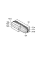
図9は、従来の駆動手段の一例である、コイルとマグネットを示す斜視図であり、図10は、従来の駆動手段を構成する、マグネットとコイルの関係を示す概略図である。
【0009】
これらの図において、101は第1のマグネットとであり、101aと101bに分極されていると共に中心に磁化されていない中立域101cを有し、不図示の地板に固定されている。102は第2のマグネットであり、第1のマグネット101と同様、102aと102bに分極されていると共に中心に磁化されていない中立域102cを有し、不図示の地板に固定されている。前記第1,第2のマグネット101,102は、それぞれ第1のヨーク103,第2のヨーク104に取り付けられており、矢印Bで示す様な磁束の流れをもつ閉磁路を構成している。105は前記第1,第2のマグネット101,102に対向するように挟まれる扁平型のコイルであり、補正光学系106を支持する支持枠107に一体的に取り付けられると共に、通電により矢印C方向に駆動される。
【0010】
なお、図10(a)は補正光学系106が駆動中心に位置する状態を、図10(b)は、補正光学系106が最大駆動量分矢印C方向に駆動され、駆動端に位置する状態を、それぞれ示している。なお、コイル105に加わる推力は、該コイル105を通る磁束密度と該コイル105に通電される電流及び磁束が通るコイルの有効長さの積となる。また、磁束が通るコイル106の有効長さは、該コイルとマグネットの対向する幅(補正光学系と一体的に構成されるコイルの駆動方向の)L0 に比例するので、該コイルに加わる推力は上記閉磁路における磁束の漏れを無視するならば、ほぼコイルとマグネットの対向する幅L0 に比例するといえる。
【0011】
【発明が解決しようとする課題】
上記従来の構成においては、コイルとマグネットの幅、及び、駆動量の関係についてあまり考慮されておらず、図10(a)の様に補正光学系106が駆動中心に位置する状態では、コイルとマグネットの対向する幅L0 が大きいものの、図10(b)の様に補正光学系106が駆動端に位置すると対向する幅L0 は極端に小さくなっている。このことは、振れ量が大きくなって、駆動端に近づくにしたがって磁束の通るコイル有効長が小さくなり、それにより、駆動力が小さくなる、或いは、それを補う分大きな電流を流さなければならない。
【0012】
上記駆動力が小さくなるという事は、大きく振れた場合の補正光学系の駆動性能を劣化させ、十分な補正ができないことであり、また、大きな電流を流すという事は、カメラのバッテリーを著しく消耗させてしまい、省電化の大きな妨げになってしまうことである。一方、やみくもにマグネット幅とコイルの巻線幅を大きくして対向する幅を増やそうとすると、駆動部が大型化するのみでなく、コイルの巻線幅を大きくすることは該コイルの重量を増やすことであり、駆動効率を劣化させる。また、コイルの巻線幅を広げることは、コイル有効長を増やす一方で、コイル全長が長くなり、コイル抵抗を増やすので、消費電力を増やすことになってしまう。つまり、駆動効率を上げるためには、磁束の通るコイル有効長を大きくするために、コイルとマグネットの対向幅は大きくする一方で、コイルの巻線幅を小さく抑えることが必要となる。
【0013】
(発明の目的)
本発明の目的は、補正光学系の駆動量が大きい場合でも、駆動手段の大型化を招くことなく、駆動効率の劣化を少なくすることのできる補正光学装置、像振れ補正装置、カメラ及び交換レンズを提供しようとするものである。
【0015】
上記目的を達成するために、本発明は、像振れを補正する為に移動可能な補正光学系と、コイルと該コイルに対向して配置されるマグネットを含み、前記コイルに通電することにより前記補正光学系を駆動する駆動手段とを有し、前記補正光学系と前記コイルとが一体的に構成された補正光学装置において、前記コイルは扁平型で中空部を有し、前記マグネットは分極された部分の中心に磁化されていない中立域を有し、前記コイルの駆動方向の幅と対向する前記マグネットの幅の関係を、前記コイルの幅に対し前記マグネットの幅を大きくすると共に、前記マグネットの幅を前記コイルの幅に前記補正光学系の最大駆動量を加えた長さ以下とし、前記コイルの前記中空部の幅と前記マグネットの前記中立域の幅と前記最大駆動量の範囲を同一に構成した補正光学装置とするものである。
【0016】
上記目的を達成するために、本発明は、振れを検出する振動検出手段と、本発明の上記補正光学装置と、前記振動検出手段の出力に基づいて前記補正光学装置内の駆動手段を制御し、前記振れに起因する像振れ補正を行う制御手段とを有する像振れ補正装置とするものである。
【0017】
上記目的を達成するために、本発明は、本発明の上記像振れ補正装置を搭載したカメラ、交換レンズとするものである。
【0018】
【発明の実施の形態】
以下、本発明を図示の実施の形態に基づいて詳細に説明する。
【0019】
図8は、手振れによる像振れを補正するシステムの図であり、図示矢印81方向のカメラ縦振れ81p及び横振れ81yに由来する像振れを補正するシステムの図である。
【0020】
同図中、82はレンズ鏡筒、83p,83yは各々カメラ縦振れ(ピッチ方向)振動、カメラ横振れ(ヨー方向)振動を検出する振動検出部であり、それぞれの振動検出方向を84p,84yで示してある。85は補正光学系(87p,87yは各々補正光学系85に推力を与えるコイル、86p,86yは補正光学系85の位置を検出する位置検手段)であり、該補正光学系85は前記検出部83p,83yの出力を目標値として駆動され、像面88での安定を確保する。
【0021】
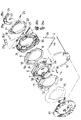
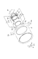
図1及び図2は本発明の実施の一形態に係る像振れ補正を行う為の補正光学装置を示す図であり、詳しくは、図1は補正光学装置の主要部の構成部品を分解して示す斜視図、図2はその作動を説明する為の断面図である。
【0022】
まず、図1を用いて簡単に本発明の実施の形態に係る補正光学装置の構成を説明する。1は像振れの補正を行うための補正光学系となる補正レンズである。2は前記補正レンズ1を保持するレンズ鏡筒であり、3は該補正光学装置全体を支持するユニット支持枠である。4はレンズ鏡筒2の光軸周りの回転を規制するL字形の支持軸であり、該レンズ鏡筒2に形成された軸受け部2aに摺動可能に係合するヨー方向に伸びる4a部と、ユニット支持枠3に形成された軸受け部3aに摺動可能に係合するピッチ方向に伸びる4b部を有する。5a,5bはレンズ鏡筒2に取り付けられるIRED(赤外発光ダイオード)であり、レンズ鏡筒2に設けられた穴部2bを通して、後述するPSD(半導体位置検出器)18a,18bに投光する。6,7は補正レンズ1をピッチ方向及びヨー方向に駆動する扁平型のコイルであり、レンズ鏡筒2に一体的に取り付けられる。8は第1のヨークであり、ユニット支持枠3に一体的に取り付けられる。9は第1のピッチ駆動マグネットであり、前記第1のヨーク8に一体的に取り付けられる。10は第1のヨー駆動マグネットであり、前記第1のヨーク8に一体的に取り付けられる。11は前述のレンズ鏡筒2を挟んでマグネット9に対向する第2のピッチ駆動マグネット、12は前述のレンズ鏡筒2を挟んでマグネット10に対向する第2のヨー駆動マグネットである。13は第2のピッチ及びヨー駆動マグネット11,12が取り付けられる第2のヨークであり、ユニット支持枠3に設けられ、レンズ鏡筒2を貫通する突起3cに一体的に取り付けられる。
【0023】
14はレンズ鏡筒2に形成された挿入穴2dに挿入されるガタ取りピンであり、ガタ取りバネ15により、前述の第2のヨーク13の端面に当接すると共に、レンズ鏡筒2に形成された不図示の突起が第1のヨーク8に当接するようにレンズ鏡筒2を付勢し、光軸方向のガタ取りを行う。16は前述のIRED5a,5bの端子及びコイル6,7の端子が半田付けされるフレキシブル基板であり、後述するハード基板17に電気的に接続される。17はユニット支持枠3に固定されるハード基板であり、PSD18a,18bが搭載されると共に前述のフレキシブル基板16とつながり、像振れ補正の電気的制御を司どる。
【0024】
19は第2のヨーク13とハード基板17間のショート防止用の板である。20は前述のユニット支持枠3に対し回転可能に係合するロックリングであり、ロックコイル21及び止めピン22を介して吸着板23が取り付けられている。24はロックヨークであり、25a,25b,25c,25dはロック用マグネットであり、これらロックヨーク24,ロック用マグネット25により、前述のロックコイル21を挟んで閉磁路を構成している。26は吸着コイルであり、吸着用ヨーク26aと吸着用ボビン26bで構成されている。27はそのバネ性により常にロックリング20を係止方向に付勢する復帰バネであり、一端がロックリング20に、他端がユニット支持枠3に、それぞれ接続される。
【0025】
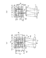
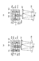
図2(a),(b)は、上記構成の補正光学装置において、像振れ補正の駆動に関して説明するために、マグネットとコイルの関係を示す断面図である。
【0026】
前述した第1のピッチ駆動マグネット9は、9aと9bに分極されていると共に中心に磁化されていない中立域9cを有し、前述したユニット支持枠3に固定されている。12は第2のピッチ駆動マグネットであり、前記第1のピッチ駆動マグネット9と同様、12aと12bに分極されていると共に中心に磁化されていない中立域12cを有し、前述したユニット支持枠3に固定されている。
【0027】
前記第1,第2のピッチ駆動マグネット9,12は、それぞれ第1のヨーク8,第2のヨーク13に一体的に取り付けられており、矢印Bに示す様な磁束の流れをもつ閉磁路を構成している。6は前記第1,第2のピッチ駆動マグネット9,12に対向するように挟まれるピッチ駆動用コイルであり、補正光学系であるところの補正レンズ1を支持する支持枠2に一体的に取り付けられると共に、通電により矢印C方向に駆動される。なお、図2(a)は、補正レンズ1が駆動中心に位置する状態を、図2(b)は補正レンズ1が最大駆動量分だけ矢印C方向に駆動され、駆動端に位置する状態を、それぞれ示している。
【0028】
上記構成において、駆動方向のコイル6の巻線幅とマグネット9,12の幅の関係は、以下に述べる理由から、コイル6の巻線幅に対しマグネット9,12の幅を大きくすると共に、前記マグネット9,12の幅を前記コイル6の巻線幅に最大駆動量を加えた長さ以下に設定している。
【0029】
ここで、図2〜図4を用いて上記のコイル6,マグネット9,12の幅の関係が最適であることを説明する。
【0030】
図2において、コイル6の巻線幅(以下、単にコイル幅とも記す)とマグネット9,12の幅(以下、単にマグネット幅)の差をaとして、その値が最大駆動量S以下である場合において、レンズ鏡筒2の外径から駆動部の最大径までのスペースをAとすると、以下の関係となる。コイル6は駆動時の最大径よりはみ出さないように、最大駆動量Sだけ外形より小さくなければならない。また、駆動時にコイル6に逆の磁束が加わらない様にコイル中空部6a及びマグネット中立域9cの各幅は最大駆動量Sだけ必要である(つまり、図2から明らかなように、コイル中空部6aの幅とマグネット中立域9cの幅と最大駆動量Sの範囲とは同一の寸法に構成されている)。さらに、駆動時にマグネット9,12とレンズ鏡筒2がぶつからないように該マグネット9,12とレンズ鏡筒2間に最大駆動量Sが必要である。以上の関係からコイルの巻線幅L1は、以下の式となる。
【0031】
L1 =(A−3S−a)/2 …………(1)
そして、図2(a)に示す様にコイル6が駆動中心に位置する場合のコイル対向幅Lu は、以下のようになる。
【0032】
Lu =Lu1+Lu2
=L1 ×2
=A−3S−a …………(2)
一方、図2(b)に示す様に最大駆動された時のコイル対向幅Lu は
Lu =Lu1+Lu2
=(A−3S−a)/2−S+(A−3S−a)−S+a
=A−5S …………(3)
である。よって、限られたスペース内にコイル6とマグネット9,12を配置する場合において、次のことがわかる。
【0033】
上記(3)式より、最大駆動時のマグネット9,12とコイル6の対向幅Lu はaに関係なく一定である。一方、コイル幅は上記(1)式で表せるので、aが大きくなるに従ってその幅は小さくなる。つまり、最大駆動端だけで評価するならば、コイル6に対しマグネット幅の差aが大きくなるにつれて、磁束の通るコイル有効長は変わらずに、コイル全長のみが小さくなるので、コイル抵抗が下がり、駆動効率が上がることとなる。但し、上記(2)式からわかるように、コイル6が駆動中心に位置する場合においては、aの増加に従ってコイル有効長は小さくなり、駆動効率が落ちるので、駆動中心,最大駆動端それぞれの駆動効率のバランスよりaの値を設定することが望ましい。例えば、防振駆動の制御上、コイル6が駆動中心近傍で駆動される確率が高いならば、aの値を小さくすれば良いし、また、駆動端まで一様の確率でコイル6が駆動されるならば、aの値を大きくすれば良い。
【0034】
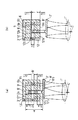
なお、aが最大駆動量Sより大きい場合は、図3に示す様に以下の関係となる。図3において、9’は第1のピッチ駆動マグネットであり、9’aと9’bに分極されていると共に中心に磁化されていない中立域9’cを有し、ユニット支持枠3に固定されている、12’は第2のピッチ駆動マグネットであり、第1のピッチ駆動マグネット9’と同様、12’aと12’bに分極されていると共に中心に磁化されていない中立域12’cを有し、ユニット支持枠3に固定されている。
【0035】
前記第1,第2のピッチ駆動マグネット9’,12’はそれぞれ第1のヨーク8’と第2のヨーク11’に取り付けられており、矢印B’に示す様な磁束の流れを持つ閉磁路を構成している。6’は前記第1,第2のピッチ駆動マグネット9’,12’に対向するように挟まれるピッチ駆動用コイルであり、補正レンズ1’を支持するユニット支持枠3’に一体的に取り付けられると共に、通電により矢印C’方向に駆動される。なお、図3(a)は補正レンズ1’が駆動中心に位置する状態を、図3(b)は補正レンズ1’が最大駆動量分だけ駆動され、駆動端に位置する状態を、それぞれ示している。
【0036】
前述と同様、コイル幅とマグネット幅の差をaとすると、レンズ鏡筒2’の外径から駆動部の最大径までのスペースをAとするならば、マグネット9’,12’が最大外形となり、コイル6’は最大外形よりはaだけ小さくなる。また、駆動時にコイル6’に逆の磁束が加わらないようにコイル中空部及びマグネット中立域の各幅は最大駆動量Sだけ必要である。さらに、駆動時にマグネット9’,12’とレンズ鏡筒2’がぶつからないようにマグネット9’,12’とレンズ鏡筒2’間に最大駆動量Sが必要である。以上の関係からコイル6’の巻線幅L2は、以下の式となる。
【0037】
L2 =(A−2S−2a)/2 …………(4)
そして、図3(a)に示す様にコイル6’が駆動中心に位置する場合のコイル対向幅Lu は、以下のようになる。
【0038】
Lu =Lu1+Lu2
=L2 ×2
=A−2S−2a …………(5)
一方、図3(b)に示す様に最大駆動された時のコイル対向幅Lu は
Lu =Lu1+Lu2
=(A−2S−2a)/2−S+(A−2S−2a)/2
=A−3S−2a …………(6)
となる。よって、上記(6)式より、aが大きくなるに従ってコイル対向幅Lu が小さくなることがわかる。また、上記(3)式と(6)式の比較から、(6)式のaはSより大きいことから、aが最大駆動量Sより大きいと、コイル対向幅Lu が小さくなり、駆動効率が不利になることがわかる。
【0039】
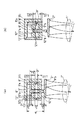
また、逆にコイル幅がマグネット幅に対しaだけ大きい場合は、図4に示すように以下の関係となる。
【0040】
図4において、9”は第1のピッチ駆動マグネットであり、9a”と9b”に分極されていると共に中心に磁化されていない中立域9c”を有し、ユニット支持枠3”に固定されている、12”は第2のピッチ駆動マグネットであり、第1のピッチ駆動マグネット9”と同様、12a”と12b”に分極されていると共に中心に磁化されていない中立域12c”を有し、ユニット支持枠3”に固定されている。
【0041】
前記第1,第2のピッチ駆動マグネット9”,12”は、それぞれ第1のヨーク8”と第2のヨーク11”に取り付けられており、矢印B”に示す様な磁束の流れをもつ閉磁路を構成している。6”は前記第1,第2のピッチ駆動マグネット9”,12”に対向するように挟まれるピッチ駆動用コイルであり、補正レンズ1”を支持するユニット支持枠2”に一体的に取り付けられると共に、通電により矢印C”方向に駆動される。なお、図4(a)は補正レンズ1”が駆動中心に位置する状態を、図4(b)は補正レンズ1”が最大駆動量分だけ駆動され、駆動端に位置する状態を、それぞれ示している。
【0042】
前述と同様、コイル幅とマグネット幅の差をaとすると、レンズ鏡筒2”の外径から駆動部の最大径までのスペースをAとするならば、コイル6”は最大外形よりはSだけ小さくなり、マグネット9”,12”はさらにaだけ小さい。また、駆動時にコイルに逆の磁束が加わらないようにコイル中空部及びマグネット中立域の各幅は最大駆動量Sだけ必要である。さらに、駆動時のマグネット9”,12”とレンズ鏡筒2”がぶつからないようにマグネット9”,12”とレンズ鏡筒2”間に最大駆動量Sが必要である。以上の関係からコイル6”の巻線幅L3は、以下の式となる。
【0043】
L3 =(A−3S−a)/2+a
=(A−3S+a)/2 …………(7)
そして、図4(a)に示す様にコイル6”が駆動中心に位置する場合のコイル対向幅Lu は、以下のようになる。
【0044】
Lu =Lu1+Lu2
=(L3 −a)×2
=A−3S−a …………(8)
一方、図4(b)に示す様に最大駆動された時のコイル対向幅Lu は
Lu =Lu1+Lu2
=(A−3S−a)/2−S+a+(A−3S−a)/2−S
=A−5S …………(9)
となる。よって、上記(9)式より、最大駆動時のマグネットとコイルの対向幅Lu はaに関係なく一定である。一方、コイル幅は上記(7)式で表せるのでaが大きくなるに従って巻線幅は大きくなる。つまり、最大駆動端だけで評価するならば、マグネット幅に対するコイル幅の差aが大きくなるにつれて、磁束の通るコイル有効長は変わらずに、コイル全長のみが大きくなるので、コイル抵抗が上がり、駆動効率が下がることとなる。さらに、上記(8)式からわかるように、コイルが駆動中心にいる場合においては、aの増加に従ってコイル有効長は小さくなり、駆動効率が落ちる。ゆえに、コイルがマグネットに対し大きくなるほど駆動効率が不利になることがわかる。
【0045】
以上より、コイルとマグネットの幅の設定が、マグネット幅がコイル幅より大きく、かつ、マグネット幅をコイル幅に最大駆動量を加えた長さ以下とすることがもっとも望ましいことがわかる。このことから、本実施の形態では、図2に示す様な関係にしている。
【0046】
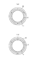
補正レンズ1の係止に関しては、ロックリング20を、図5に示すように回転させて、図5(a)の状態で係止し、図5(b)の状態で解除を行う。
【0047】
係止状態から解除状態への駆動は、ロック用ヨーク24,ロック用マグネット25により形成される閉磁路内に配置されたロックコイル21への通電により、ロックリング20を回転させて行う。ロックリング20の解除状態の保持は吸着コイル26に通電し、ロックリング20と一体の吸着板23を吸着することにより行う。解除状態から係止状態への駆動は、吸着コイル24の通電を切ることにより、ロックリング20は復帰バネ27の復帰力により係止方向へと回され、ロックリング20がストッパピン28に当接して回転が規制され係止状態が保持される。
【0048】
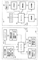
図6は、上記の補正光学装置を有する像振れ補正装置を搭載した一眼レフカメラの電気的構成を示すブロック図である。
【0049】
同図中、200はカメラ本体、300は交換レンズ本体を示している。201はマイクロコンピュータで構成されるカメラCPUで、後述の如くカメラ本体200内の種々の回路の動作を制御すると共に、レンズ本体300の装着時にはカメラ接点202を介してレンズCPU301との通信を行うものである。203は外部より操作可能な電源スイッチであり、カメラCPU201を立ち上げてシステム内の各アクチュエータやセンサ等への電源供給及びシステムの動作を可能な状態とするためのスイッチである。204は外部より操作可能な2段ストローク式のレリーズスイッチで、その信号はカメラCPU201に入力される。
【0050】
カメラCPU201はレリーズスイッチ204より入力された信号に従い、第1ストロークスイッチがON(SW1信号発生)であれば測光回路205による露光量の決定や合焦動作等を行い撮影準備状態に入り、第2ストロークスイッチがON(SW2信号発生)まで操作されたことを検知すると、レンズ本体300内のレンズCPU301(後述の如くレンズ本体300内の種々の装置の動作を制御すると共に、カメラ本体200に装着された時にはレンズ接点302を介してカメラCPU201との通信を行うもの)に後述の絞り動作命令を送信し、かつ、露光回路206に露光開始命令を送信して実際の露光動作を行わせ、露光終了信号を受信すると給送回路207に給送開始命令を送信してフィルムの巻き上げ動作を行わせる。208は測距回路であり、レリーズスイッチ204の第1ストロークスイッチがONされる(SW1信号が発生する)ことによりカメラCPU201から送信されてくる測距開始命令に従い測距エリア内に存在する被写体を測距し、これに焦点を合せるために必要な合焦レンズの移動量を決定しカメラCPU201に送信する。
【0051】
303は外部より操作可能な像振れ作動スイッチ(以下、ISスイッチと記す)であり、後述の像振れ補正動作(以下、IS動作とも記す)を行わせるかどうかを選択すること(ONでIS動作選択)が可能である。304は振動検出装置であり、レンズCPU301からの命令に従い、カメラの縦振れ及び横振れの加速度あるいは速度等を検出する振動検出部304aと、該振動検出部304aの出力信号を電気的あるいは機械的に積分した変位をレンズCPU301に出力する演算部304bとから構成されている。
【0052】
305は図1及び図2で詳述した補正光学装置であり、レンズCPU301によってそれぞれ制御される以下の四つの構成部品に大別される。第1は、主として補正レンズ1より成る補正光学系305a、第2は、前記補正光学系305aをピッチ方向やヨー方向に駆動するマグネット9,10,12,13、コイル6,7とから成る駆動手段305b、第3は、主としてIRED及びPSDより成る位置検出手段305c、第4は、前記補正光学系305aを係止状態に保持する為に、ロックリング20を回転させ、係止状態から解除状態へと駆動するロック用ヨーク24,ロック用マグネット25,ロックコイル21及び、ロックリング20の解除状態を保持する吸着コイル26を有する係止手段305dである。
【0053】
尚、前記補正光学装置305、ISスイッチ303、振動検出装置304、これらを制御するレンズCPU301が、像振れ補正装置を構成する。
【0054】
306は合焦装置であり、前述の如くカメラCPU201から送信された合焦レンズの移動量に従い、レンズCPU301によって制御される駆動回路306aと、該駆動回路306aによって駆動される合焦レンズ306bとから構成されている。307は絞り装置であり、前述の如くカメラCPU201から送信された絞り動作命令に従い、レンズCPU301によって制御される駆動回路307aと、該駆動回路307aによって駆動され開口面積を決定する絞り部材307bとから構成されている。
【0055】
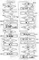
図7は、上記カメラの主要動作を示すフローチャートである。
【0056】
まず、カメラ本体200の電源スイッチ203がONされ、レンズ本体300に電源の供給が開始(又は、新しい電池を入れられた場合、カメラ本体200にレンズ本体300が装着された場合などカメラ本体200とレンズ本体300との間で通信が開始)されたことを判別すると(#5001のYES)、次にカメラCPU201がレリーズスイッチ204にSW1信号が発生しているか否かを判別する(#5002)。この結果、発生していればレンズCPU301がISスイッチ303がON(IS動作選択)になっているかを次に判別し(#5004)、IS動作が選択されていればステップ#5004へ、選択されていなければステップ#5018へ進む。ステップ#5004では、レンズCPU301が内部タイマをスタートさせ、次にカメラCPU201が測光,AF(測距動作)、レンズCPU301がAF(合焦動作)、振れ検出の開始、更には駆動手段305bによる振れ補正制御を可能にする為に、ロック用ヨーク24、ロック用マグネット25により形成される閉磁路内に配置されたロックコイル21への通電を行い、ロックリング20を回転させて解除を行う(つまり、係止手段305dの係止を解除する)と共に、吸着コイル26に通電してロックリング20と一体の吸着板23を吸着してロックリング20の解除状態の保持を行う(#5005)。
【0057】
次に、レンズCPU301が上記タイマでの計時内容が所定の時間t1 に達したか否かを調べ、達していなければ達するまでこのステップに留まる(#5006)。これは、振動検出装置304の出力が安定するまでの時間待機する為の処理である。その後、所定の時間t1 が経過すると、振動検出装置304の出力による目標値信号と位置検出手段305cの出力に基づいて駆動手段305bを介して補正光学系305aを駆動し、振れ補正制御を開始する(#5007)。
【0058】
次に、カメラCPU201がレリーズスイッチ204にSW2信号が発生しているか否かを調べ(#5008)、発生していなければ再びSW1信号が発生しているか否かの判別を行い(#5010)、もしSW1信号も発生していなければ、レンズCPU301が振れ補正制御を停止する(#5011)と共に、補正光学系305aを所定の位置(光軸中心位置)に係止手段305dにより係止する(#5012)。
【0059】
また、前記ステップ#5008でSW2信号は発生していないが、ステップ#5010でSW1信号が発生していると判別した場合はステップ#5008へ戻る。そして、このステップ#5008でレリーズスイッチ204のSW2信号が発生したことを判別すると、レンズCPU301が絞り装置307を制御し、同時にカメラCPU201が露光回路206を介してフィルムへの露光動作を行う(#5009)。次いで、カメラCPU201がSW1信号の状態を調べ(#5010)、該SW1信号が発生しなくなったらレンズCPU301が振れ補正制御を停止する(#5011)と共に、補正光学系305aを所定の位置(光軸中心位置)に係止手段305dにより係止する(#5012)。具体的には、解除状態から係止状態への駆動は、吸着コイル26の通電を切ることにより、ロックリング20は復帰バネ27の復帰力により係止方向へと回され、ロックリング20が、ストッパーピン28に当接して回転が規制され係止状態が保持されることにより行う。
【0060】
以上の動作を終了すると、次にレンズCPU301は上記タイマを一旦リセットして再度スタートさせ(#5013)、再びSW1信号が所定時間t2 内に発生するかどうかの判別を行う(#5014→#5015→#5014……)。もし振れ補正を停止してから所定時間t2 内に再度SW1信号が発生したならば、測光,AF(測距動作及び合焦動作)及び補正光学系305aの係止解除を行い(#5016)、振れ検出はそのまま継続されているので、直ちに目標値信号と位置検出手段305cの出力に基づいて補正光学系305aを駆動し、振れ補正制御を再び開始する(#5007)。
【0061】
以下前述と同様の動作を繰り返す。この様な処理をすることにより、前述した様に撮影者がレリーズ操作を停止した後に再度レリーズ操作をした際に、その度に振動検出装置304を起動してその出力安定まで待機するといった不都合を無くすことが可能になる。
【0062】
一方、振れ補正を停止してから所定時間t2 以内にSW1信号が発生しなかった場合は(#5015→#5014のYES)、振れ検出を停止(振動検出装置304の動作を停止)する(#5017)。その後はステップ#5002に戻り、SW1信号の発生待機の状態に入る。
【0063】
上記ステップ#5003でIS動作が選択されていなければステップ#5018へ進み、位置検出手段305cにて補正光学系305aの位置を検出し、補正光学系305aが係止位置有ると判別した場合にはステップ#5020へ進み、係止位置に無いと判別した場合にはステップ#5019へ進み、補正光学系305aを係止位置まで駆動する。つまり、ガタ取りピン10を第2ヨーク109に形成された係合溝109aに係合させて該補正光学系305aを係止する。
【0064】
次のステップ#5020では、カメラCPU201が測光,AF(測距動作)を、レンズCPU301がAF(合焦動作)を、それぞれ実行する。そして、次にカメラCPU201がレリーズスイッチ204のSW2信号が発生しているか否かを調べ(#5021)、発生していなければ再びSW1信号が発生しているか否かの判別を行い(#5023)、もしSW1信号も発生していなければステップ#5002に戻り、SW1信号の発生待機の状態に入る。また、ステップ#5023でSW2信号は発生していないがSW1信号は発生していれば、ステップ#5021へ戻る。そして、このステップ#5021でレリーズスイッチ204にSW2信号が発生したことを検知すると、レンズCPU301が絞り装置307を制御し、同時にカメラCPU201が露光回路206を介してフィルムへの露光動作を行う(#5022)。次いで、カメラCPU201がSW1信号の状態を調べ(#5023)、SW1信号が発生していなければステップ#5022からステップ#5002へ戻る。
【0065】
本実施の形態に係るレンズ交換式の一眼レフカメラでは、電源スイッチ203がOFFされるまで上記一連の動作を繰り返し、OFFされるとカメラCPU201とレンズCPU301との通信が終了しレンズ本体300への電源供給が終了する。なお、上記シーケンスにおいて、ISスイッチ303がOFF(像振れ補正OFF)と判断された場合、常に、補正光学系305aの位置検出を行うので(ステップ#5018)、不用意に係止状態が外れていた場合には、必ず係止状態へと駆動する(ステップ#5019)ようになっているので、衝撃時の係止はずれの対策が施されている。
【0066】
上記の実施の形態によれば、像振れを補正する為の補正レンズ1を駆動する、扁平型のコイル6,7とこれらに対向して配置されるマグネット9〜12から成る、像振れを補正する為の補正レンズ1を駆動する駆動手段を有する補正光学装置において、前記コイル6,7の駆動方向の幅とマグネット9〜12の幅の関係を、コイル6,7の幅に対しマグネット9〜12の幅を大きくすると共に、該マグネット9〜12の幅を前記コイル6,7の幅に補正レンズ1の最大駆動量を加えた長さ以下とするようにしているため、前記補正レンズの駆動量が大きい場合でも、前記コイルとマグネットの対向する幅が著しく小さくなることが無いので駆動効率の劣化が少なくでき、前記駆動手段の大型化を防止することが可能となり、該装置のスペース効率を良好なものにすることができる。
【0067】
上記の実施の形態と本発明の関係は、既に説明した通りであるが、本発明は、これら実施の形態の構成に限定されるものではなく、請求項で示した機能、又は実施の形態がもつ機能が達成できる構成であればどのようなものであってもよいことは言うまでもない。
【0068】
(変形例)本発明は、カメラに適用した例を述べているが、これに限定されるものではなく、補正光学装置を具備した装置やその他の防振を必要とする装置、更には移動部材を所定の方向に往復動させる駆動装置への適用も可能である。
【0069】
【発明の効果】
以上説明したように、本発明によれば、補正光学系の駆動量が大きい場合でも、駆動手段の大型化を招くことなく、駆動効率の劣化を少なくすることができる補正光学装置、像振れ補正装置、カメラ又は交換レンズを提供できるものである。
【図面の簡単な説明】
【図1】本発明の実施一形態に係る補正光学装置の主要構成部品を示す分解斜視図である。
【図2】本発明の実施一形態に係る駆動手段を成すコイルとマグネットの構造について説明する為の断面図である。
【図3】図2のコイルとマグネットの構造が理想であることを説明する為に、他のコイルとマグネットの構造について説明する為の断面図である。
【図4】同じく図2のコイルとマグネットの構造が理想であることを説明する為に、更に別のコイルとマグネットの構造について説明する為の断面図である。
【図5】本発明の実施一形態に係る係止手段について説明する為の正面図である。
【図6】本発明の実施一形態に係る補正光学装置を具備した像振れ補正補正装置を搭載したカメラの要部構成を示すブロック図である。
【図7】図6のカメラの一連の動作を示すフローチャートである。
【図8】一般的な像振れ補正を行うシステムの概略構成を示す斜視図である。
【図9】従来の補正光学系を駆動する駆動手段を成すコイルとマグネットの関係を示す斜視図である。
【図10】従来の駆動手段を構成するコイルとマグネットの構造を示す断面図である。
【符号の説明】
1 補正レンズ(補正光学系)
2 レンズ保持枠
3 ユニット支持枠
6,7 扁平型のコイル
9〜12 マグネット
301 レンズCPU
304 振動検出装置
305 補正光学装置
305a 補正光学系
305b 駆動手段[0001]
BACKGROUND OF THE INVENTION
The present invention relates to a correction optical device having a correction optical system, an image shake correction device having the correction optical device, a camera equipped with the image shake correction device, Improvement of interchangeable lens It is about.
[0002]
[Prior art]
Since the current camera automates all the important tasks for shooting such as determining the exposure and focusing, the possibility of shooting failure is very low even for those who are unskilled in camera operation.
[0003]
Recently, a system for correcting image blur due to camera shake applied to the camera has been studied, and the factor that causes the photographer to fail in shooting has almost disappeared.
[0004]
Here, a system for correcting image blur due to camera shake will be briefly described.
[0005]
The camera shake at the time of shooting is usually a vibration of 1 Hz to 12 Hz as a frequency. However, even if such a camera shake occurs at the shutter release time, it is possible to take a photograph without image shake. As described above, it is necessary to detect the vibration of the camera due to the camera shake and to displace the correction lens in accordance with the detected value. Therefore, in order to be able to take a photograph that does not cause image shake even if camera shake occurs, first, the camera vibration is detected accurately, and second, the optical axis change due to camera vibration is corrected lens. It is necessary to correct by displacing.
[0006]
In principle, this vibration (camera shake) is detected by a vibration detector that detects acceleration, speed, etc., and an operation that outputs displacement by electrically or mechanically integrating the output signal of the vibration detector. It can be performed by mounting a vibration detection device comprising a part on a camera. Then, based on this detection information, image blur correction can be performed by controlling the correction optical device in the image blur correction device mounted to change the photographing optical axis by displacing the correction optical system.
[0007]
As a conventional example of the driving means of the correction optical system, a driving unit that uses a coil and a magnet opposed to the coil, arranges the magnet in the fixed unit, arranges the coil in the correction optical system, and drives the coil by energizing the current. Is used to detect a shake in a vertical shake direction (hereinafter referred to as a pitch direction) when the camera is held in a normal position and a horizontal shake direction (hereinafter referred to as a yaw direction) perpendicular thereto. In order to correct the two directions of the pitch and yaw of the drive unit, there has been proposed a drive means for independently driving each of the two directions.
[0008]
FIG. 9 is a perspective view showing a coil and a magnet as an example of a conventional driving means, and FIG. 10 is a schematic diagram showing a relationship between the magnet and the coil constituting the conventional driving means.
[0009]
In these drawings,
[0010]
10A shows a state in which the correction
[0011]
[Problems to be solved by the invention]
In the above conventional configuration, the relationship between the coil and magnet width and the drive amount is not considered so much, and when the correction
[0012]
The fact that the driving force is small means that the driving performance of the correction optical system is deteriorated when it shakes greatly, and that sufficient correction cannot be performed. In addition, the flow of a large current significantly consumes the camera battery. This is a big hindrance to power saving. On the other hand, when trying to increase the opposing width by increasing the magnet width and the coil winding width, not only does the drive section increase in size, but increasing the coil winding width increases the weight of the coil. That is, the driving efficiency is deteriorated. Further, widening the winding width of the coil increases the effective coil length while increasing the overall coil length and increasing the coil resistance, resulting in an increase in power consumption. That is, in order to increase the driving efficiency, in order to increase the effective coil length through which the magnetic flux passes, it is necessary to increase the opposing width between the coil and the magnet while keeping the coil winding width small.
[0013]
(Object of invention)
SUMMARY OF THE INVENTION An object of the present invention is to provide a correction optical device, an image blur correction device, and a camera that can reduce the deterioration of drive efficiency without increasing the size of the drive means even when the drive amount of the correction optical system is large. And interchangeable lenses Is to provide.
[0015]
In order to achieve the above object, the present invention includes a correction optical system movable to correct image blur, a coil and a magnet disposed opposite to the coil, and the coil is energized to energize the coil. Driving means for driving the correction optical system, the correction optical system and the coil When In the correction optical device constructed integrally, the coil is flat and has a hollow portion, the magnet has a neutral region that is not magnetized at the center of the polarized portion, and is arranged in the driving direction of the coil. The relationship between the width of the magnet facing the width and the width of the coil is larger than the width of the coil, and the width of the magnet is the length of the coil plus the maximum drive amount of the correction optical system. The correction optical device is configured as follows, in which the width of the hollow portion of the coil, the width of the neutral region of the magnet, and the range of the maximum drive amount are configured to be the same.
[0016]
To achieve the above objective, The present invention Is Control for performing image blur correction due to the shake by controlling the vibration detection means for detecting shake, the correction optical apparatus of the present invention, and the drive means in the correction optical apparatus based on the output of the vibration detection means. And image blur correction apparatus It is what.
[0017]
In order to achieve the above object, the present invention provides a camera equipped with the image blur correction device of the present invention, interchangeable lens It is what.
[0018]
DETAILED DESCRIPTION OF THE INVENTION
Hereinafter, the present invention will be described in detail based on illustrated embodiments.
[0019]
FIG. 8 is a diagram of a system that corrects image blur due to camera shake, and is a diagram of a system that corrects image blur caused by the camera
[0020]
In the figure, 82 is a lens barrel, 83p and 83y are vibration detection units for detecting camera vertical shake (pitch direction) vibration and camera horizontal shake (yaw direction) vibration, respectively. The respective vibration detection directions are 84p and 84y. It is shown by. 85 is a correction optical system ( 87 p, 87 y is a coil for applying thrust to the correction
[0021]
1 and 2 are diagrams showing a correction optical apparatus for performing image blur correction according to an embodiment of the present invention. Specifically, FIG. 1 is an exploded view of components of a main part of the correction optical apparatus. FIG. 2 is a sectional view for explaining the operation.
[0022]
First, the configuration of a correction optical apparatus according to an embodiment of the present invention will be briefly described with reference to FIG.
[0023]
A
[0024]
[0025]
FIGS. 2A and 2B are cross-sectional views showing the relationship between a magnet and a coil in order to explain driving of image blur correction in the correction optical apparatus having the above configuration.
[0026]
The first
[0027]
The first and second
[0028]
In the above configuration, the relationship between the winding width of the
[0029]
Here, it will be described with reference to FIGS. 2 to 4 that the width relationship between the
[0030]
In FIG. 2, when the difference between the winding width of the coil 6 (hereinafter also simply referred to as the coil width) and the width of the
[0031]
L 1 = (A-3S-a) / 2 (1)
As shown in FIG. 2A, the coil facing width Lu when the
[0032]
Lu = Lu1 + Lu2
= L 1 × 2
= A-3S-a (2)
On the other hand, as shown in FIG.
Lu = Lu1 + Lu2
= (A-3S-a) / 2-S + (A-3S-a) -S + a
= A-5S (3)
It is. Therefore, in the case where the
[0033]
From the above equation (3), the facing width Lu between the
[0034]
When a is larger than the maximum drive amount S, the following relationship is established as shown in FIG. In FIG. 3, reference numeral 9 'denotes a first pitch drive magnet, which has a neutral region 9'c polarized at 9'a and 9'b and not magnetized at the center, and fixed to the
[0035]
The first and second pitch drive magnets 9 'and 12' are attached to the first yoke 8 'and the second yoke 11', respectively, and are closed magnetic paths having a magnetic flux flow as indicated by an arrow B '. Is configured.
[0036]
Similarly to the above, if the difference between the coil width and the magnet width is a, and the space from the outer diameter of the
[0037]
L 2 = (A-2S-2a) / 2 (4)
Then, as shown in FIG. 3A, the coil facing width Lu when the coil 6 'is located at the drive center is as follows.
[0038]
Lu = Lu1 + Lu2
= L 2 × 2
= A-2S-2a (5)
On the other hand, as shown in FIG.
Lu = Lu1 + Lu2
= (A-2S-2a) / 2-S + (A-2S-2a) / 2
= A-3S-2a (6)
It becomes. Therefore, from the above equation (6), it can be seen that the coil facing width Lu decreases as a increases. Also, from the comparison of the above formulas (3) and (6), a in formula (6) is larger than S, so that when a is larger than the maximum drive amount S, the coil facing width Lu becomes small and the drive efficiency is reduced. It turns out that it becomes disadvantageous.
[0039]
On the contrary, when the coil width is larger than the magnet width by a, the following relationship is obtained as shown in FIG.
[0040]
In FIG. 4, 9 ″ is a first pitch drive magnet, which has a
[0041]
The first and second
[0042]
Similarly to the above, if the difference between the coil width and the magnet width is a, if the space from the outer diameter of the
[0043]
L Three = (A-3S-a) / 2 + a
= (A-3S + a) / 2 (7)
As shown in FIG. 4A, the coil facing width Lu when the
[0044]
Lu = Lu1 + Lu2
= (L Three -A) x 2
= A-3S-a (8)
On the other hand, as shown in FIG. 4B, the coil facing width Lu when the maximum driving is performed is
Lu = Lu1 + Lu2
= (A-3S-a) / 2-S + a + (A-3S-a) / 2-S
= A-5S (9)
It becomes. Therefore, from the above equation (9), the facing width Lu between the magnet and the coil at the maximum drive is constant regardless of a. On the other hand, since the coil width can be expressed by the above equation (7), the winding width increases as a increases. In other words, if only the maximum drive end is evaluated, as the coil width difference a with respect to the magnet width increases, the effective coil length through which the magnetic flux passes does not change, and only the entire coil length increases. Efficiency will decrease. Further, as can be seen from the above equation (8), when the coil is at the driving center, the effective coil length decreases as a increases, and the driving efficiency decreases. Therefore, it turns out that drive efficiency becomes disadvantageous, so that a coil becomes large with respect to a magnet.
[0045]
From the above, it can be seen that it is most desirable to set the width of the coil and the magnet so that the magnet width is larger than the coil width and the magnet width is equal to or smaller than the coil width plus the maximum drive amount. Therefore, in this embodiment, the relationship is as shown in FIG.
[0046]
Regarding the locking of the
[0047]
Driving from the locked state to the released state is performed by rotating the
[0048]
FIG. 6 is a block diagram showing an electrical configuration of a single-lens reflex camera equipped with an image shake correction apparatus having the correction optical apparatus described above.
[0049]
In the figure,
[0050]
If the first stroke switch is ON (SW1 signal is generated), the
[0051]
[0052]
[0053]
The correction
[0054]
[0055]
FIG. These are flowcharts showing main operations of the camera.
[0056]
First, the
[0057]
Next, the
[0058]
Next, the
[0059]
In
[0060]
When the above operation is completed, the
[0061]
Thereafter, the same operation as described above is repeated. By performing such a process, as described above, when the photographer stops the release operation and then performs the release operation again, the
[0062]
On the other hand, a predetermined time t after the shake correction is stopped 2 If the SW1 signal is not generated within the range (YES in # 5015 → # 5014), the shake detection is stopped (the operation of the
[0063]
If the IS operation is not selected in
[0064]
In the
[0065]
In the interchangeable lens single-lens reflex camera according to the present embodiment, the above-described series of operations is repeated until the
[0066]
According to the above-described embodiment, the image blur is corrected, which includes the
[0067]
The relationship between the above embodiments and the present invention is as described above. However, the present invention is not limited to the configurations of these embodiments, and the functions shown in the claims or the embodiments are not limited thereto. It goes without saying that any configuration can be used as long as the functions it has can be achieved.
[0068]
(Modification) The present invention describes an example applied to a camera. However, the present invention is not limited to this. The present invention is not limited to this, and a device provided with a correction optical device, other devices requiring vibration isolation, and a moving member. The Predetermined Application to a drive device that reciprocates in the direction is also possible.
[0069]
【The invention's effect】
As described above, according to the present invention, even when the correction optical system has a large driving amount, the correction optical apparatus and the image blur correction that can reduce the deterioration of the driving efficiency without increasing the size of the driving unit. Equipment, camera Or interchangeable lens Can be provided.
[Brief description of the drawings]
FIG. 1 is an exploded perspective view showing main components of a correction optical apparatus according to an embodiment of the present invention.
FIG. 2 is a cross-sectional view for explaining the structure of a coil and a magnet constituting a driving unit according to an embodiment of the present invention.
FIG. 3 is a cross-sectional view for explaining the structure of another coil and magnet in order to explain that the structure of the coil and magnet of FIG. 2 is ideal;
4 is a cross-sectional view for explaining still another coil and magnet structure in order to explain that the coil and magnet structure of FIG. 2 is ideal. FIG.
FIG. 5 is a front view for explaining locking means according to the embodiment of the present invention.
FIG. 6 is a block diagram showing a main configuration of a camera equipped with an image blur correction device including the correction optical device according to the embodiment of the present invention.
7 is a flowchart showing a series of operations of the camera shown in FIG. 6;
FIG. 8 is a perspective view illustrating a schematic configuration of a system that performs general image blur correction.
FIG. 9 is a perspective view showing a relationship between a coil and a magnet constituting a driving means for driving a conventional correction optical system.
FIG. 10 is a cross-sectional view showing the structure of a coil and a magnet constituting conventional driving means.
[Explanation of symbols]
1 Correction lens (correction optical system)
2 Lens holding frame
3 Unit support frame
6,7 Flat coil
9-12 magnet
301 Lens CPU
304 Vibration detection device
305 Correction optical device
305a Correction optical system
305b Driving means
Claims (5)
前記コイルは扁平型で中空部を有し、
前記マグネットは分極された部分の中心に磁化されていない中立域を有し、
前記コイルの駆動方向の幅と対向する前記マグネットの幅の関係を、前記コイルの幅に対し前記マグネットの幅を大きくすると共に、前記マグネットの幅を前記コイルの幅に前記補正光学系の最大駆動量を加えた長さ以下とし、
前記コイルの前記中空部の幅と前記マグネットの前記中立域の幅と前記最大駆動量の範囲を同一に構成したことを特徴とする補正光学装置。A correction optical system movable to correct image blur; and a driving means for driving the correction optical system by energizing the coil, including a coil and a magnet disposed opposite to the coil. In the correction optical apparatus in which the correction optical system and the coil are integrally configured,
The coil is flat and has a hollow portion;
The magnet has a neutral region that is not magnetized at the center of the polarized portion;
The relationship between the width of the coil in the driving direction and the width of the magnet facing the coil is such that the width of the magnet is increased relative to the width of the coil, and the maximum width of the correction optical system is driven to the width of the coil. Less than the length plus the amount,
A correction optical apparatus, wherein a width of the hollow portion of the coil, a width of the neutral region of the magnet, and a range of the maximum drive amount are configured to be the same.
Priority Applications (2)
| Application Number | Priority Date | Filing Date | Title |
|---|---|---|---|
| JP19811698A JP4181663B2 (en) | 1998-06-30 | 1998-06-30 | Correction optical device, image shake correction device, camera, and interchangeable lens |
| US09/342,221 US6327433B1 (en) | 1998-06-30 | 1999-06-29 | Image blur correction apparatus |
Applications Claiming Priority (1)
| Application Number | Priority Date | Filing Date | Title |
|---|---|---|---|
| JP19811698A JP4181663B2 (en) | 1998-06-30 | 1998-06-30 | Correction optical device, image shake correction device, camera, and interchangeable lens |
Publications (3)
| Publication Number | Publication Date |
|---|---|
| JP2000019577A JP2000019577A (en) | 2000-01-21 |
| JP2000019577A5 JP2000019577A5 (en) | 2005-10-20 |
| JP4181663B2 true JP4181663B2 (en) | 2008-11-19 |
Family
ID=16385740
Family Applications (1)
| Application Number | Title | Priority Date | Filing Date |
|---|---|---|---|
| JP19811698A Expired - Fee Related JP4181663B2 (en) | 1998-06-30 | 1998-06-30 | Correction optical device, image shake correction device, camera, and interchangeable lens |
Country Status (2)
| Country | Link |
|---|---|
| US (1) | US6327433B1 (en) |
| JP (1) | JP4181663B2 (en) |
Cited By (1)
| Publication number | Priority date | Publication date | Assignee | Title |
|---|---|---|---|---|
| CN102292673A (en) * | 2009-01-23 | 2011-12-21 | 株式会社图丽 | Voice coil motor for driving correction lens, image shake correcting apparatus, interchangeable lens, and optical instrument |
Families Citing this family (24)
| Publication number | Priority date | Publication date | Assignee | Title |
|---|---|---|---|---|
| US6738570B2 (en) | 2002-01-04 | 2004-05-18 | Canon Kabushiki Kaisha | Lens apparatus having vapor-resistant ventilation and optical instrument using lens apparatus |
| JP2005345504A (en) * | 2004-05-31 | 2005-12-15 | Pentax Corp | Image blur correction device |
| US7684685B2 (en) * | 2005-06-07 | 2010-03-23 | Sony Corporation | Image stabilizer, lens barrel and imager apparatus |
| JP4792844B2 (en) * | 2005-07-11 | 2011-10-12 | ソニー株式会社 | Image blur correction device, lens device, and imaging device |
| JP2007156352A (en) * | 2005-12-08 | 2007-06-21 | Sony Corp | LENS DEVICE AND IMAGING DEVICE |
| US7782533B2 (en) * | 2006-02-10 | 2010-08-24 | Panasonic Corporation | Image stabilizing apparatus |
| JP4823934B2 (en) * | 2006-02-10 | 2011-11-24 | パナソニック株式会社 | Image blur correction device, lens barrel, and imaging device |
| JP5009036B2 (en) * | 2007-04-19 | 2012-08-22 | オリンパス株式会社 | Imaging device |
| JP2008310175A (en) * | 2007-06-15 | 2008-12-25 | Fujinon Corp | Image blur correction unit, image blur correction device, photographing device, and portable device |
| JP2008310172A (en) * | 2007-06-15 | 2008-12-25 | Fujinon Corp | Image blur correction unit, image blur correction device, photographing device, and portable device |
| JP5258309B2 (en) * | 2008-01-18 | 2013-08-07 | キヤノン株式会社 | Optical image stabilizer and optical apparatus |
| TWI377370B (en) * | 2008-06-03 | 2012-11-21 | Asia Optical Co Inc | Image blur correction device |
| CN101609246B (en) * | 2008-06-17 | 2011-05-04 | 亚洲光学股份有限公司 | Image shock suppression device |
| JP5348235B2 (en) * | 2009-08-21 | 2013-11-20 | ミツミ電機株式会社 | Lens holder driving device and camera equipped with the same |
| CN102130567A (en) * | 2011-01-21 | 2011-07-20 | 清华大学 | Voice coil motor |
| KR101500034B1 (en) * | 2012-06-29 | 2015-03-06 | 엘지이노텍 주식회사 | Camera module |
| KR102128937B1 (en) * | 2013-05-29 | 2020-07-01 | 엘지이노텍 주식회사 | Camera module |
| CN115061257B (en) | 2013-05-29 | 2024-04-26 | Lg伊诺特有限公司 | Lens driving device, camera module and mobile phone |
| JP6214316B2 (en) | 2013-10-09 | 2017-10-18 | キヤノン株式会社 | Image blur correction device, lens device, imaging device, image blur correction device control method, program, and storage medium |
| JP6659113B2 (en) | 2015-10-26 | 2020-03-04 | キヤノン株式会社 | Optical equipment |
| JP6716281B2 (en) | 2016-02-19 | 2020-07-01 | キヤノン株式会社 | Drive device, control method thereof, control program, and imaging device |
| KR102251859B1 (en) * | 2020-06-25 | 2021-05-14 | 엘지이노텍 주식회사 | Camera module |
| KR102164907B1 (en) * | 2020-06-25 | 2020-10-13 | 엘지이노텍 주식회사 | Camera module |
| KR102217569B1 (en) * | 2020-10-06 | 2021-02-18 | 엘지이노텍 주식회사 | Camera module |
Family Cites Families (8)
| Publication number | Priority date | Publication date | Assignee | Title |
|---|---|---|---|---|
| JPS63107431U (en) | 1986-12-26 | 1988-07-11 | ||
| US4963905A (en) | 1987-12-04 | 1990-10-16 | Canon Kabushiki Kaisha | Camera |
| JPH06118292A (en) | 1992-09-30 | 1994-04-28 | Canon Inc | Zoom lens and camera system capable of close-up photography |
| JPH08201676A (en) | 1995-01-31 | 1996-08-09 | Canon Inc | Optical barrel and optical equipment using the same |
| JP3858308B2 (en) * | 1996-09-10 | 2006-12-13 | 株式会社ニコン | Blur correction device, lens barrel having blur correction device, and camera having blur correction device |
| US5974269A (en) | 1996-11-07 | 1999-10-26 | Canon Kabushiki Kaisha | Image blur preventing apparatus |
| US5937212A (en) | 1996-11-15 | 1999-08-10 | Canon Kabushiki Kaisha | Image pickup apparatus |
| US5995762A (en) * | 1997-05-12 | 1999-11-30 | Asahi Kogaku Kogyo Kabushiki Kaisha | Lens driving mechanism |
-
1998
- 1998-06-30 JP JP19811698A patent/JP4181663B2/en not_active Expired - Fee Related
-
1999
- 1999-06-29 US US09/342,221 patent/US6327433B1/en not_active Expired - Lifetime
Cited By (2)
| Publication number | Priority date | Publication date | Assignee | Title |
|---|---|---|---|---|
| CN102292673A (en) * | 2009-01-23 | 2011-12-21 | 株式会社图丽 | Voice coil motor for driving correction lens, image shake correcting apparatus, interchangeable lens, and optical instrument |
| US8817375B2 (en) | 2009-01-23 | 2014-08-26 | Kenko Tokina Co., Ltd. | Correction-lens-moving voice coil motor, anti-vibration device, interchangeable lens unit and optical apparatus |
Also Published As
| Publication number | Publication date |
|---|---|
| JP2000019577A (en) | 2000-01-21 |
| US6327433B1 (en) | 2001-12-04 |
Similar Documents
| Publication | Publication Date | Title |
|---|---|---|
| JP4181663B2 (en) | Correction optical device, image shake correction device, camera, and interchangeable lens | |
| JP2000231129A (en) | Image stabilizer | |
| JP4886418B2 (en) | Optical device and camera system | |
| JP2000235206A (en) | Supporting state detection device, camera with image blur correction function, interchangeable lens with image blur correction function, and device for image blur correction | |
| JP3792845B2 (en) | Optical device | |
| US6819503B2 (en) | Lens barrel | |
| JPH10142647A (en) | Image blur prevention device | |
| JP2005173160A (en) | Image stabilization apparatus and optical apparatus | |
| JP2002196384A (en) | Optical device and photographing device | |
| JP3720404B2 (en) | Vibration correction means locking device | |
| JP2000122106A (en) | Optical equipment and camera | |
| JP2001228498A (en) | Image stabilizer | |
| JP3791057B2 (en) | Blur correction device, photographing optical system, and camera | |
| JP2002214660A (en) | Correction optics | |
| JP2002268108A (en) | Correction optics | |
| JP3869916B2 (en) | Image stabilization device, optical apparatus, and single-lens reflex camera | |
| JPH0961880A (en) | Lens barrel and optical equipment using the same | |
| JPH11316399A (en) | Image blur correction device and optical apparatus using the same | |
| JPH11119279A (en) | Image stabilization device | |
| JPH1039353A (en) | Image stabilizer | |
| JP3188739B2 (en) | Anti-sway device | |
| JP2002214661A (en) | Correction optics | |
| JP3800675B2 (en) | Blur correction device and camera | |
| JP2000330156A (en) | Optical equipment with image stabilization function | |
| JPH10293334A (en) | Position control device and correction optical device |
Legal Events
| Date | Code | Title | Description |
|---|---|---|---|
| A521 | Written amendment |
Free format text: JAPANESE INTERMEDIATE CODE: A523 Effective date: 20050616 |
|
| A621 | Written request for application examination |
Free format text: JAPANESE INTERMEDIATE CODE: A621 Effective date: 20050616 |
|
| A977 | Report on retrieval |
Free format text: JAPANESE INTERMEDIATE CODE: A971007 Effective date: 20070126 |
|
| A131 | Notification of reasons for refusal |
Free format text: JAPANESE INTERMEDIATE CODE: A131 Effective date: 20071127 |
|
| A521 | Written amendment |
Free format text: JAPANESE INTERMEDIATE CODE: A523 Effective date: 20080128 |
|
| A131 | Notification of reasons for refusal |
Free format text: JAPANESE INTERMEDIATE CODE: A131 Effective date: 20080520 |
|
| A521 | Written amendment |
Free format text: JAPANESE INTERMEDIATE CODE: A523 Effective date: 20080718 |
|
| TRDD | Decision of grant or rejection written | ||
| A01 | Written decision to grant a patent or to grant a registration (utility model) |
Free format text: JAPANESE INTERMEDIATE CODE: A01 Effective date: 20080812 |
|
| A01 | Written decision to grant a patent or to grant a registration (utility model) |
Free format text: JAPANESE INTERMEDIATE CODE: A01 |
|
| A61 | First payment of annual fees (during grant procedure) |
Free format text: JAPANESE INTERMEDIATE CODE: A61 Effective date: 20080901 |
|
| R150 | Certificate of patent or registration of utility model |
Free format text: JAPANESE INTERMEDIATE CODE: R150 |
|
| FPAY | Renewal fee payment (event date is renewal date of database) |
Free format text: PAYMENT UNTIL: 20110905 Year of fee payment: 3 |
|
| FPAY | Renewal fee payment (event date is renewal date of database) |
Free format text: PAYMENT UNTIL: 20110905 Year of fee payment: 3 |
|
| FPAY | Renewal fee payment (event date is renewal date of database) |
Free format text: PAYMENT UNTIL: 20120905 Year of fee payment: 4 |
|
| FPAY | Renewal fee payment (event date is renewal date of database) |
Free format text: PAYMENT UNTIL: 20120905 Year of fee payment: 4 |
|
| FPAY | Renewal fee payment (event date is renewal date of database) |
Free format text: PAYMENT UNTIL: 20130905 Year of fee payment: 5 |
|
| LAPS | Cancellation because of no payment of annual fees |