JP3780080B2 - Optical device - Google Patents
Optical device Download PDFInfo
- Publication number
- JP3780080B2 JP3780080B2 JP29965297A JP29965297A JP3780080B2 JP 3780080 B2 JP3780080 B2 JP 3780080B2 JP 29965297 A JP29965297 A JP 29965297A JP 29965297 A JP29965297 A JP 29965297A JP 3780080 B2 JP3780080 B2 JP 3780080B2
- Authority
- JP
- Japan
- Prior art keywords
- state
- lens
- camera
- stepping motor
- correction
- Prior art date
- Legal status (The legal status is an assumption and is not a legal conclusion. Google has not performed a legal analysis and makes no representation as to the accuracy of the status listed.)
- Expired - Fee Related
Links
Images


Description
【0001】
【発明の属する技術分野】
本発明は、ステッピングモータを駆動源として係止部材の位置を制御する光学装置の改良に関するものである。
【0002】
【従来の技術】
現在のカメラは露出決定やピント合せ等の撮影にとって重要な作業は全て自動化されているため、カメラの操作に未熟な人でも撮影失敗を起こす可能性は非常に少なくなっている。
【0003】
また最近では、カメラに加わる手振れによる像振れを補正するシステムも研究されており、撮影者の撮影失敗を誘発する要因は殆ど無くなってきている。
【0004】
ここで、手振れによる像振れを補正するシステムについて簡単に説明する。
【0005】
撮影時のカメラの手振れは、周波数として通常1Hz乃至12Hzの振動であるが、シャッタのレリーズ時点においてこのような手振れを起していても像振れの無い写真を撮影可能とするため、基本的な考えとして上記手振れによるカメラの振動を検出し、その検出値に応じて補正レンズを変位させてやらなければならない。従って、手振れが生じても像振れを生じない写真を撮影可能とするためには、第1に、カメラの振動を正確に検出すること、第2に、カメラの振動による光軸変化を補正レンズを変位させて補正することが必要となる。
【0006】
この振動(カメラ振れ)の検出は、原理的にいえば、加速度,速度等を検出する振動検出部と、該振動検出部の出力信号を電気的あるいは機械的に積分して変位を出力する積分器等を具備した演算部などにより成る振動検出装置等をカメラに搭載することによって行うことができる。そして、この検出情報に基づいて、撮影光軸を変化させるべく搭載された像振れ補正装置内の補正光学装置を制御する、つまり補正レンズを変位させることにより、像振れ補正が可能となる。
【0007】
また、多くの従来例(特開昭62−18875号,特開平7−98469号,特開平7−98469号等)では、上記補正光学装置内に前記補正レンズの変位を機械的に固定係止することのできる係止部材を有しており、像振れ補正動作の必要がない時(像振れ補正装置を搭載した交換レンズがカメラ本体から取り外された状態や像振れ作動スイッチがオフされた状態など)には、CPU等の制御手段によって制御される駆動手段が係止部材を移動させ、補正レンズの光軸と他のレンズの光軸とを一致させるように固定係止することで、補正レンズのガタ付きによる外乱振動(携帯時に加わる振動など)での破損及び補正光学装置による無駄な電力消費の防止を行っている。
【0008】
更には、前記係止部材の駆動部を為す駆動源として、ステッピングモータを用いた提案も本出願人によって種々なされている。これらは、ステッピングモータのディテントトルクによる安定位置での自己保持力の大きさを利用し前記係止部材を保持することが可能な構成となっているため、係止部材を係止状態及び非係止状態に保持するための電力を必要とせず、しかも安定して保持することが可能となっている。
【0009】
【発明が解決しようとする課題】
しかしながら、上記従来例における像振れ補正装置では以下のような問題点が解決されずに残っていた。
【0010】
第1に、像振れ補正動作を行なっている最中にパンニングなどの大きなカメラ姿勢の変更操作が行なわれると、その操作による光軸変化を打ち消そうとして補正レンズが可動範囲の機械的端まで急激に駆動され、激しく機械的端への衝突を繰り返すことで電力を浪費してしまうだけでなく、当接部に打痕ができてしまい、その後の係止部材の駆動の妨げ(引っ掛かり)の原因となる場合があった。
【0011】
第2に、例えば係止部材駆動装置の駆動源としてステッピングモータを用いた上記従来例においては、パンニングなどの大きなカメラ姿勢の変更操作が行なわれている最中に係止部材を駆動した場合、補正レンズにかかる慣性力に抗して係止部材を駆動しなければならず、通常のカメラ操作状態における駆動に比べて負荷トルクが大きく(不安定に)なるため、ステッピングモータが駆動パルス信号に追従できず、係止部材の係止及び非係止状態間の駆動が確実に行われない場合があった。あるいは、係止部材を自己保持力で係止状態や非係止状態に保持している場合でも、やはりパンニングなどの急激で大きなカメラ姿勢の変更操作が行なわれることで係止部材に働く慣性力によって、ステッピングモータが係止部材を保持し続けることができずにディテントトルクに抗して他の安定位置にずれてしまうことがあり、その後の制御における駆動パルス信号に追従できず、係止部材切換え不良の現象発生に至る場合があった。
【0012】
(発明の目的)本発明の目的は、係止部材を係止状態もしくは非係止状態に保持している最中に、急激かつ大きな姿勢変更が為されたとしても、係止部材の係止状態もしくは非係止状態を保持し続けることのできる光学装置を提供しようとするものである。
【0017】
【課題を解決するための手段】
上記目的を達成するために、本発明は、振れに起因する像振れを補正するために移動可能な補正光学系と、前記振れを検出する振動検出手段と、前記補正光学系を移動させないように係止する係止状態と移動可能な非係止状態とに設定する係止部材と、前記係止部材を前記係止状態から前記非係止状態へ、もしくは、前記非係止状態から前記係止状態へ変更するために、前記係止部材を移動させるステッピングモータと、前記係止部材を前記係止状態と前記非係止状態のうちの一方の状態から他方の状態へ移動させるよう前記ステッピングモータへの駆動信号を出力する駆動制御手段とを有し、前記駆動制御手段が、前記振動検出手段の出力に基づいて、前記振れが予め決められた値より小さい場合には、第1の駆動信号を前記ステッピングモータに出力し、前記振れが予め決められた値より大きい場合には、前記第 1 の駆動信号より通電時間の長い第2の駆動信号を前記ステッピングモータに出力する光学装置とするものである。
【0027】
【発明の実施の形態】
以下、本発明を図示の実施の形態に基づいて詳細に説明する。
【0028】
図1は本発明の実施の一形態に係る手振れによる像振れを補正するシステム(補正光学装置や振動検出装置等を具備した像振れ補正装置)の概略を示す構成図であり、図中の矢印81方向のカメラ縦振れ81p及び横振れ81yに由来する像振れを補正するシステムを示すものである。
【0029】
同図において、82はレンズ鏡筒、83p,83yは各々カメラ縦振れ振動、カメラ横振れ振動を検出する振動検出部で、それぞれの振動検出方向を84p,84yで示してある。85は補正光学装置(87p,87yは各々補正レンズに推力を与えるコイル、86p,86yは該補正レンズの位置を検出する位置検出素子)であり、該補正光学装置85は振動検出センサ83p,83yの出力を目標値として駆動され、像面88での安定を確保する。
【0030】
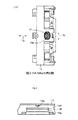
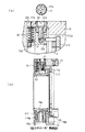
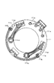
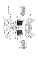
図2〜図15は本発明の実施の一形態に係る像振れ補正装置における補正光学装置の機械的構成やステッピングモータの働きについて説明する為の図であり、図2は補正光学装置の主要部の構成部品を分解して示す斜視図、図3は図2の左方向から見た補正光学装置を示す(説明の為、ハード基板111は取り外し、内部が見える様にしてある)図、図4(a)は図3の矢印A方向より見た図、図4(b)は補正レンズ11の位置検出に関する部分の構成を示す図、図5は図3のB−B’断面図(尚、図5(a)は図5(b)の一部を拡大して示す平面及び断面図)、図6はコイルユニットの平面,側面及び断面を示す図、図7は本実施の形態における振れ補正用の駆動手段の構成を従来構成との比較により説明する為の図、図8は図2等に示したハード基板111を示す図、図9は図2等に示した支持枠12や地板13を図3に示した面の裏面側より見て示す図、図10は図2等に示したロックリング113やローリング規制リング112を図3に示した面より見て示す図、図11はロックリング113による支持枠12の係止,係止時を説明する為の図、図12はステッピングモータ19の構成部品を分解して示す斜視図、図13はステッピングモータ19におけるマグネットロータ193とステータヨーク191,192の位置関係を示す図、図14はステッピングモータ19におけるコイル通電のタイミングチャート、図15はステッピングモータ19の停止位置とロックリング113の状態の関係を示した図である。
【0031】
まず、図2を用いて簡単に本発明の実施の一形態に係る像振れ補正装置における補正光学装置の構成を説明する。
【0032】
補正レンズ11は支持枠12に支持され、支持枠12が地板13に結合される。そして、後述する永久磁石やコイル等より成る駆動手段によって、前記補正レンズ11及び支持枠12より成る補正光学系がピッチ方向114p及びヨー方向114yに駆動され、像振れが補正される。113はロックリングであり、後述するステッピングモータ19の出力がラック113aに伝わることにより、前記支持枠12、つまり補正光学系を所定の位置に係止することになる。112はローリング規制リングであり、3本の軸部112a1〜112a3を地板13を介して前記支持枠12に嵌合することで、該支持枠12の光軸回りのローリングを規制する事になる。111は前述のステッピングモータやコイル、更には位置検出手段を成す後述のホール素子などの各種の端子が同一平面上に集中して配線されることになるハード基板(プリント基板)である。
【0033】
以下、詳細な構成について、図3以降の各図を用いて説明する。
【0034】
12は補正レンズ11を支持する支持枠(図3及び図9参照)であり、該支持枠12に図5等に示す永久磁石14p,14y(図3ではヨーク15p,15yに隠されて見えない)が吸着したヨーク15p,15yがカシメ或はネジ止めで固定されている。
【0035】
13は地板であり、該地板13の永久磁石14p,14yとの対向面に、コイル16p,16yが取り付けられている(図5(b)参照)。このコイル16p(16yも同様)は、図6に示す様に、樹脂材のコイル枠16aと一体成形されており、コイル枠16aに圧入された導電部材である端子ピン16bにコイル16pの両端子が接続されてユニット化されており、端子ピン16bが後述するハード基板111に貫通して半田付けされる。尚、図6(a)はコイルユニット16の平面図、図6(b)は側面図、図6(c)は図5(b)のC−C’断面図である。
【0036】
以上の様にして構成される、補正光学系の駆動手段を成すヨーク15p,15y、永久磁石14p,14y、コイル16p,16yの関係について、図7を用いて説明する。尚、図7(a)は本発明の実施の一形態を示し、図7(b)は適切でない例を示し、図7(c)は従来例を示したものである。
【0037】
図7(c)の従来例においては、コイル76p,76yは支持枠75に取り付けられていた。そして、永久磁石73は図示の様に第1のヨーク712と第2のヨーク72とにより破線73bで示す閉磁路を形成している。この様に閉磁路を形成するのは、それにより磁束の流れが整い、駆動効率が向上する為である。
【0038】
本発明の実施の形態において、支持枠12に永久磁石14p(14y)を取り付ける場合、閉磁路を形成する為には、図7(b)に示す様に、支持枠12上に永久磁石14p,14y及びこれに対向する位置に対向ヨーク15ap,15ayを設ければ良い。これにより、閉磁路14aが形成される。
【0039】
しかしながら、本発明の実施の形態においては、対向ヨーク15ap,15ayを設ける事による駆動効率の向上と、該対向ヨーク15ap,15ayを取り付ける事による重量増加がもたらす追従性の悪化のバランスの観点から、図7(a)に示す様に、対向ヨークを設けず、閉磁路使用を行っている。つまり、駆動効率を向上させる事よりも、重量を増加させない事により消費電力の絶対値が少なく出来る事に着目した構成にしている。
【0040】
支持枠12には、図3及び図9に示す様に、3方向に放射状に腕部12aが延出し、これら腕部12aにコロ17がネジ止めされ(詳しくは、図5(a)に示す様にネジ17aを介して)、このコロ17が次述のようにして地板13の案内溝13a(図2及び図4(a)参照)に嵌挿される。案内溝13aは図4(a)に示す様に矢印13b方向に延びる長穴となっている為、3点の各コロ17はこの方向に移動出来る。即ち、支持枠12は地板13を含む平面内に、総ての方向に自由に摺動可能となる(図4(a)の光軸方向13cにのみ位置規制される)。
【0041】
組立時には、前記支持枠12の腕部12aの3ケ所のうちの1ケ所或は2ケ所にコロ17をネジ止めし、ネジ止めした該コロ17を地板13の案内溝13aに嵌挿させて支持枠12を地板13上に乗せ、最後に残りの案内溝13aを通して同じく残りのコロ17を支持枠12の腕部12aにネジ止めする事で、地板13への支持枠12の組み込みが終了する。
【0042】
ここで、上記のコロ17を図5(a)に示す様な偏心コロにする事で、補正レンズ11の傾き調整が可能である(尚、図5(a)は前述した様に図5(b)の一部を拡大した平面及び断面図である)。つまり、コロ17を回転させる事で、腕部12aは光軸方向に前後するので、3つの腕部12aの光軸方向の位置を該コロ17によって調整する事で、補正レンズ11の傾きを調整でき、調整後にネジ17aを締め付ける事でコロ17を腕部12aに回転不能にできる。
【0043】
地板13には、図3に示した面の裏面側より、図10(a−1),(a−2)に示すロックリング113が回転可能に支持されており、同じくモータ地板198(図3参照)を介して地板13に取り付けられたステッピングモータ19(図3及び図12,図13参照、詳細については後述する)のロータ193に設けられたギヤ193aが地板13の穴13m(図9(b)参照)を貫通してくるラック113aと噛み合って、該ロックリング113を回転方向に駆動することができる。この時、ロックリング113の回転許容範囲は、地板13の穴13mにおける回転方向の端面13nとロックリング113におけるラック113aの端面113e(図10(a−1)参照)とがそれぞれ当接する間の範囲に限られている。このロックリング113に設けられた4箇所のカム部113bは、図9(a)に示す4点突起12bとの関係で、支持枠12の係止,非係止を行うことで、係止手段として機能している。
【0044】
つまり、図10(a−1)に示すロックリング113を反時計方向に回転させると、図11(a)に示す通り、該ロックリング113のカム部113bが支持枠12の突起12bと離れる為、支持枠12はロックリング113に対してフリー(非係止状態)になる。また、ロックリング113を時計方向に回転させると、図11(b)に示す通り、カム部113bの平坦部113cが突起12bと接触して、支持枠12とロックリング113が係合する。即ち、支持枠12を地板13に対してロックさせる。
【0045】
従って、振れ補正を行う時には、ステッピングモータ19によりロックリング113を反時計回りに駆動して支持枠12をロックリング113に対してフリーな状態(非係止状態)にし、一方、振れ補正終了時には、ロックリング113を時計回りに回転駆動して支持枠12を地板13に対しロックさせた状態(係止状態)にすることになる。
【0046】
上述した様に、支持枠12は地板13に対しコロ17と案内溝13aで結合し、光軸方向に位置規制されている。この支持方法は組立性に優れ、地板13に案内溝13aが一体成形されている事、及び、コロ17と案内溝13aの孔の間の嵌合管理は行い易い(一般に、レンズ鏡筒で多く使用されているコロとカムの関係を考えると理解し易い)。更にコロ17を公知の偏心コロにする事で、支持枠12と地板13間の傾きを、該コロ17の回転で調整出来るメリットが有る。
【0047】
しかしながら、上記支持方法の場合、支持枠12は図3に示すピッチ方向114p及びヨー方向114y(振れ補正方向)に自由に動くことが出来る他に、ローリング方向114rにも回転してしまう。この回転は振れ補正精度を悪化させてしまう。
【0048】
そこで、本実施の形態では、上記ローリングの影響を少なくする為に、以下の方法を採っている。
【0049】
図9(b)は図3の地板13のみを裏から見た図であり、114y方向に延びる長穴13d1 ,13d2 ,13d3 が設けられている。この長穴13d1 ,13d2 ,13d3 に、図10(b−1),(b−2)に示すローリング規制リング112から紙面裏方向に延出する軸部112a1 ,112a2 ,112a3 が各々貫通する。前記軸部112a1 と長穴13d1 、軸112a3 と長穴13d3 は各々嵌合関係にあり、この2点からローリング規制リング112は地板13に対し114y方向にのみ移動可能となる。
【0050】
前記長穴13d2 は長穴13d1 ,13d3 に比べて大きくなっており(図面ではほぼ同様に描いているが)、軸112a2 との嵌合ガタを大きくしている。これは、3つの軸部112a1 ,112a2 ,112a3 とも嵌合にすると重複嵌合になる為、ローリング規制リング112と地板13の間の動きが渋くなる為である。即ち、3つの長穴の中でいずれか1つを大きく開けておく方が好ましい。
【0051】
今、長穴13d1 を基準に考えると、114y方向のスパンは長穴13d2 より長穴13d3 の方が長い。よって、長穴13d1 と長穴13d3 を嵌合穴とすると、軸部112a1 ,112a3 との嵌合ガタが生じた場合でもローリング規制リング112と地板13間のローリングガタを少なく抑えられる。(長穴13d1 と長穴13d2 を嵌合穴とすると、両者の114y方向のスパンが短い為、ローリングガタは大きくなる)
ローリング規制リング112は地板13に設けられた爪13k(図5(b)及び図9(b)参照)で光軸方向に弾性的に係合規制される。該ローリング規制リングの軸部112a1 ,112a2 ,112a3 は地板13を貫いて支持枠12の裏面に設けられた114p方向に延びる長穴12c1 ,12c2 ,12c3 に入る(図9(a)の支持枠裏面図及び図5(b)参照)。ここでも長穴12c1 と軸部112a1 ,12c2 と軸部112a2 を嵌合関係にして、長穴12c3 を大きく設定する事で、重複嵌合を避けている。この時に長穴12c3 を大きく開ける理由も長穴13dの場合と同様である。よって、支持枠12はローリング規制リング112に対し114p方向にのみ移動可能である。
【0052】
以上の様な構成にする事で、支持枠12は地板13に対して114p,114y方向にのみ移動可能で、ローリング方向114rには規制されるが、実際には軸部112aと長穴13d,12b間の嵌合ガタ分による微少なローリングは未だ残るため、支持枠12上の腕部12aに設けられたフック12dと地板13の周囲に設けられたフック13eの間にはバネ18が設けられている(図3及び図5参照)。前記バネ18は、図3に示す様に、支持枠12の中心から放射状に3方向に延びており、支持枠12を八つ裂き状態に引っ張っている。フック12dは支持枠12の中心から径方向に大きく離れた位置に設けてある為、支持枠12にローリング方向の力が働いた場合、その力を八つ裂き方向に配置されたバネの弾性力で抑える事が出来る。即ち、弾性的にローリング規制を行っている為に微小なローリングガタが生じない様にできる。
【0053】
図8は図2,図4(b),図5(b)に示すハード基板111であり、図示のパターン111cp,111cyの裏面側に、後述する位置検出手段であるホール素子110p,110y(図3でもその位置関係のみ図示してある)がリフローで結合されている。尚、位置検出手段として、ホール素子を用いた例を示しているが、MR素子等の磁気検出手段であれば良い。又、フォトリフレクタ等の光学的検出手段を用いても良い。
【0054】
このハード基板111を地板13の位置決めピン13fと該ハード基板111の穴111dをガイドにして地板13に取り付け、ネジを穴111eに貫通させネジ穴13gにネジ止め(図3参照)する。この時、前述した様にユニット化されたコイルの端子ピン16bは図3の紙面上方向に延出しており、後述するステッピングモータ19のコイル194及び195(図12参照)の接続端子194a,194b,195a,195bもこの方向に延びているため、自然に端子ピン16bと接続端子194a,194b,195a,195bも各々穴111b,111a(図8参照)に貫通する。穴111a,111bはスルーホールになっており、ここで端子ピン16p,19aと半田付けして電気的接続を行う。
【0055】
ハード基板111に取り付けられる位置検出手段としては、前述の様にホール素子110p,110yを用いている(図4(b)や図7(a)参照)。
【0056】
以下、図7(a)を用いて、その動作を説明する。
【0057】
ホール素子110p(110y)は周囲の磁界の変化に対応して出力を変化させる。図7(a)において、ホール素子110p(110y)は両極着磁した永久磁石14p(14y)と対向しており、支持枠12の駆動(例えば、ピッチ方向114p)につれてホール素子110p(110y)と永久磁石14p(14y)の関係がズレてくる為、該ホール素子110p(110y)に加わる磁界強度が変化し、該ホール素子110p(110y)はそれに対応する出力を行う事で支持枠12の位置を検出する。
【0058】
図12は前述のステッピングモータ19の構成部品を分解して示す斜視図である。
【0059】
191は軟磁性体の板を複数枚(6枚)を積層して固着したステータヨークであり、軟磁性体の板はそれぞれ同形状の板を重ね合わせて積層してユニット化されている。
【0060】
192はステータヨーク191と同一部品であり、2相タイプのステッピングモータのもう片方のステータヨークになるものである。このステータヨーク192はステータヨーク191を裏返しにして使用している。
【0061】
193はステータヨーク191とステータヨーク192の励磁状態により回転可能となるプラスチックマグネット製のロータであり、その外周は分割的に且つ交互に複数着磁なされ、そのロータ193の回転力をロックリング113のラック113aに伝達する為のギヤ193aが一体的に設けられている。194,195はそれぞれステータヨーク191とステータヨーク192を励磁する為のコイルであり、コイル194とコイル195は同一部品で構成されている。コイル194とコイル195は接続端子194a,194b,195a,195bから通電されることによりそれぞれステータヨーク191,ステータヨーク192を励磁する構成である。
【0062】
196はステータヨーク191とステータヨーク192を位置決め支持すると共に、前記ロータ193の回転軸193bを回転軸支しているモータケースであって、前述のモータ地板198を介して地板13に取り付けられている。もちろんモータケース196を地板13に一体的に設けるように構成することも可能である。
【0063】
197はモータケース蓋であり、前記ロータ193の回転軸193cを回転軸支すると共に、爪部197a〜197dをモータケース196の溝部196c〜196fにそれぞれ引っ掛けることにより、電磁駆動装置としてのユニット化されたステッピングモータ19が構成されている。
【0064】
次に、以上の構成によるステッピングモータ19の動作を説明する。
【0065】
コイル194,195へ接続端子194a,194b,195a,195bを介して通電することにより、ステータヨーク191,192に磁界が発生し、ロータ193の磁界と作用し合い閉磁路を形成する。このときコイル195に通電されていなければ通電されたコイル194によって生じた磁路が支配的となり、ロータ193に回転トルクを発生させる(コイル195のみの通電時も同じ)。また、両コイル194,195に通電された場合も同様にステータヨーク192,193にそれぞれ磁路を形成され、ロータ193と作用し合い、ロータ193に回転トルクを与える。従って、両方のコイル194,195に順次電流方向を切り換えながら通電することにより、従来から周知であるステッピングモータの駆動を行う事ができ、ロータ193のギヤ部193aとロックリング113のラック113aとの噛み合いにより、ロックリング113を所定角度回転させることができる。
【0066】
図13(a)〜(h)はステッピングモータ19におけるロータ193とステータヨーク191,192との位置関係を示した図である。
【0067】
各図において、ロータ193の外周に着磁された極及びコイル194,195への通電によってステータヨーク191,192に発生する極については、N及びSの表記がされている。
【0068】
図13(a)は、ステータヨーク191に表記の極が発生する方向にコイル194に通電している状態(以下、この状態を“A相通電状態”とし、逆方向への通電状態を“/A相通電状態”とする)である。このような状態の時はロータ193の極がステータヨーク191に発生した極と引き付け合っているため、ステータヨーク191に対してロータ193の極が対向して停止しており、その際ステータヨーク192とロータ193の極は対向しないでロータ193の着磁ピッチPの1/2(=P/2)ずれて停止している。つまり、ステータヨーク191と192の配置は「nP+(P/2):(nは整数)」ずれるように配慮されている。また、この状態において通電をストップした場合でも、ロータ193の極がステータヨーク191と引き付け合っているため、ロータ193はそのまま停止していることができる。つまり、機械的安定位置にある。
【0069】
以下の説明では、この様に通電を切ってもロータ193が停止していることができる位置を、“安定位置”あるいは“1相通電位置”と称することとする。
【0070】
図13(b)は、コイル194にA相通電,ステータヨーク192に表記の極が発生する方向にコイル195に通電している状態(以下、この状態を“B相通電状態”とし、逆方向への通電状態を“/B相通電状態”とする)である。図13(a)の状態からA,B相通電を行うと、ロータ193の極と各ステータに発生した極とが反発あるいは引き付け合い、ロータ193は時計方向にP/4だけ回転してバランスを保って図13(b)の状態で停止する。また、この状態において通電をストップした場合は、ロータ193の極がステータヨーク191あるいは192のどちらかを引き付けようとするため、ロータ193はそのままの位置では停止していることができず、図13(a)の状態あるいは後述の図13(c)の状態に移動してしまう。
【0071】
以下の説明では、この様に通電を切るとロータ193が停止していることができない位置を、“不安定位置”あるいは“2相通電位置”と称する。
【0072】
図13(c)は、図13(b)の状態からコイル194への通電を切り、コイル195にB相通電を行った状態の図であり、この時ステータヨーク192には表記の極が発生するため、ロータ193の極と引き付け合い、図13(b)の状態に対してロータ193が更に時計方向にP/4回転することになる。また、この状態は(a)と同じく安定位置となっている。
【0073】
以下、図13(d)は/A・B相通電、図13(e)は/A相通電、図13(f)は/A・/B相通電、図13(g)は/B相通電、図13(h)はA・/B相通電を行った状態の図で、それぞれ前の図に対してロータ193は時計方向にP/4回転しているが、原理はそれぞれ図13(a)〜(c)と同様なので動作説明は省略する。
【0074】
以上説明した様な動作原理に基づいて、図14にコイル通電のタイミングチャートを示す。尚、図14の横軸はパルス数(又は時間)、縦軸には通電の状態を示してあり、下段には通電相及び図13(a)〜(h)の状態との対応を表記してある。
【0075】
この図より、通電相の状態は8通りの組合せができることがわかり、この時の1通りの組合せを1パルスとカウントする事とすると、9パルス目以降は再び1パルス目からの位相分を通電することによりロータ193を任意の角度まで回転させることができる。また、図13(a)〜(h)の状態を逆に辿ることによりロータ193を反時計方向にP/4ずつ回転させることも当然可能である。
【0076】
図15は、図12〜図14で説明した1,2相駆動によるステッピングモータ19のロータ193の停止位置と、図11に示したロックリング113の状態との関係を示した図である。
【0077】
図中、ロータ193が通電をしなくても止まれる位置(1相通電位置)を白丸、2つのコイルに同時通電して止まれる位置(2相通電位置)を黒丸で表すこととし、下段にはその位置での通電相を示してある。aは図11(b)に示した様にロックリング113が係止状態の位置、bは図11(a)に示した様にロックリング113が非係止状態の位置におけるロータ193の位置であって、本実施の形態ではともに機械的安定位置であるA相通電状態の位置としているため、駆動終了後に通電を切った場合でも停止位置が安定し、そのままの位置に停止していることができる。
【0078】
図16は、本発明に係る図2〜図15で説明した補正光学装置を含む像振れ補正装置を搭載した、レンズ交換式オートフォーカス(AF)一眼レフカメラシステムの電気的構成を示すブロック図である。
【0079】
図中、200はカメラ本体、300は交換レンズ本体を示している。201はマイクロコンピュータで構成されるカメラCPUで、後述の如くカメラ本体200内の種々の回路の動作を制御すると共に、レンズ本体300の装着時にはカメラ接点202を介してレンズCPU301との通信を行うものである。203は外部より操作可能な電源スイッチであり、カメラCPU201を立ち上げてシステム内の各アクチュエータやセンサ等への電源供給及びシステムの動作を可能な状態とするためのスイッチである。204は外部より操作可能な2段ストローク式のレリーズスイッチで、その信号はカメラCPU201に入力される。
【0080】
カメラCPU201はレリーズスイッチ204より入力された信号に従い、第1ストロークスイッチがON(SW1信号発生)であれば測光回路205による露光量の決定や合焦動作等を行い撮影準備状態に入り、第2ストロークスイッチがON(SW2信号発生)まで操作されたことを検知すると、レンズ本体300内のレンズCPU301(後述の如くレンズ本体300内の種々の装置の動作を制御すると共に、カメラ本体200に装着された時にはレンズ接点302を介してカメラCPU201との通信を行うもの)に後述の絞り動作命令を送信し、かつ、露光回路206に露光開始命令を送信して実際の露光動作を行わせ、露光終了信号を受信すると給送回路207に給送開始命令を送信してフィルムの巻き上げ動作を行わせる。208は測距回路であり、レリーズスイッチ204の第1ストロークスイッチがONされる(SW1信号が発生する)ことによりカメラCPU201から送信されてくる測距開始命令に従い測距エリア内に存在する被写体を測距し、これに焦点を合せるために必要な合焦レンズの移動量を決定しカメラCPU201に送信する。
【0081】
303は外部より操作可能な像振れ作動スイッチ(以下、ISスイッチと記す)であり、後述の像振れ補正動作(以下、IS動作とも記す)を行わせるかどうかを選択すること(ONでIS動作選択)が可能である。304は振動検出装置であり、レンズCPU301からの命令に従い、カメラの縦振れ及び横振れの加速度あるいは速度等を検出する振動検出部304aと、該振動検出部304aの出力信号を電気的あるいは機械的に積分した変位をレンズCPU301に出力する演算部304bとから構成されている。
【0082】
305は図2〜図15で詳述した補正光学装置であり、レンズCPU301によってそれぞれ制御される以下の五つの構成部品に大別される。第1は、主として補正レンズ11,支持枠12とから成る補正光学系305a、第2は、主として永久磁石14p,14y、コイル16p,16yとから成り、補正レンズ11を移動させるための駆動手段305b、第3は、主として永久磁石14p,14y、ホール素子110p,110yとから成り、移動した補正レンズ11の位置を検出するための位置検出手段305c、第4は、主としてステッピングモータ19、係止部材であるロックリング113、支持枠12の突起12bとから成り、必要に応じて補正レンズ11を所定位置(光軸中心位置)に係止することのできる係止手段305d、第5は、ステッピングモータ19から成り、前記ロックリング113を駆動する駆動手段305eである。
【0083】
尚、前記補正光学装置305、ISスイッチ303、振動検出装置304、これらを制御するレンズCPU301が、像振れ補正装置を構成する。
【0084】
306は合焦装置であり、前述の如くカメラCPU201から送信された合焦レンズの移動量に従い、レンズCPU301によって制御される駆動回路306aと、該駆動回路306aによって駆動される合焦レンズ306bとから構成されている。307は絞り装置であり、前述の如くカメラCPU201から送信された絞り動作命令に従い、レンズCPU301によって制御される駆動回路307aと、該駆動回路307aによって駆動され開口面積を決定する絞り部材307bとから構成されている。
【0085】
図17及び図18は、図16に示したカメラシステムにおける主要動作を示すフローチャートである。
【0086】
まず、ステップ#5001にて、カメラ本体200の電源スイッチ203がONされ、レンズ本体300に電源の供給が開始(または、新しい電池が入れられた場合、カメラ本体200にレンズ本体300が装着された場合など、カメラ本体200とレンズ本体300との間で通信が開始)されると、次のステップ#5002にて、カメラCPU201がレリーズスイッチ204にSW1信号が発生しているか否かを判別し、該SW1信号が発生していなければ発生するまでこのステップに留まる。その後、前記SW1信号が発生するとステップ#5003へ進み、ここではレンズCPU301がISスイッチ303がON(IS動作選択)になっているかを判別する。この結果、IS動作が選択されていればステップ#5004へ進み、選択されていなければステップ#5036へ進む。
【0087】
ステップ#5004では、レンズCPU301が内部タイマをスタートさせ、次のステップ#5005にて、カメラCPU201が測光,AF(測距動作)を、レンズCPU301がAF(合焦動作),振れ検出の開始を、ぞれぞれ行なう。続くステップ#5006では、レンズCPU301が上記タイマの計時内容が所定の時間t1に達したか否かを調べ、達していなければ達するまでこのステップに留まる。これは、振動検出装置304の出力が安定するまで時間待機する為の処理である。
【0088】
その後、所定の時間t1が経過すると、ステップ#5006からステップ#5007へ進み、レンズCPU301が振動検出装置304の出力から演算したカメラ振れの振幅を所定値a1と比較し、所定値a1より小さくなるまでこのステップに留まる。これにより、カメラ振れが大きすぎて振れ補正制御、あるいは、係止手段305dにかかる慣性力によって該係止手段305dの解除動作が不可能な時には、該係止手段305dの解除動作を行なわないように構成されている。ここでは判定の条件を「カメラ振れの振幅」としているが、振動数を条件として基準値を設定して同様の動作を行なわせることも可能である。
【0089】
その後、所定値a1より小さくなった時点でステップ#5008へ進み、今度はレンズCPU301は振動検出装置304の出力から演算したカメラ振れの振幅を所定値a2(<a1)と比較し、所定値a2より大きければステップ#5010へ進み、小さければステップ#5009へ進む。そして、両ステップでレンズCPU301は上記ステップ#5008での判定結果に基づき、それぞれ補正光学系305aによる振れ補正制御を可能にする為に係止手段305dの解除を行うよう、ステッピングモータ19に補正レンズ及び係止部材に加わる慣性力に合わせた通電(第1または第2の駆動パターン通電)を行なう。
【0090】
具体的な例を挙げると、慣性力がより大きく働くステップ#5010での通電相(図13で既述)切換え時間間隔を、あらかじめステップ#5009における間隔よりも長く設定して記憶させておき、上記ステップ#5008での判定結果に応じた駆動パターンの通電を選択して行なうようにしておくことで、通常状態ではより短時間での駆動が可能(タイムラグが短い)となり、通常の駆動に比べて負荷トルクが大きく(不安定に)なっている場合でも、ステッピングモータ19が駆動パルス信号に追従できない不都合が解消できる。
【0091】
上記の様な過程で、係止手段305dによる補正光学系305aの係止が解除されると、次のステップ#5011にて、レンズCPU301は振動検出装置304の出力による目標値信号と位置検出手段305bの出力に基づいて補正光学系305aを駆動し、振れ補正制御を開始する。
【0092】
次に、図18のステップ#5012へ進み、ここではカメラCPU201がレリーズスイッチ204にSW2信号が発生しているか否かを調べ、該SW2信号が発生していなければ直ちにステップ#5014へ進み、再びSW1信号が発生しているか否かの判別を行い、もしSW1信号も発生していなければステップ#5015へ進み、レンズCPU301は振れ補正制御を停止し、次のステップ#5016にて、再びレンズCPU301は振動検出装置304の出力から演算したカメラ振れの振幅を所定値a2と比較し、所定値a2より小さければステップ#5017へ進み、大きければステップ#5018へ進む。そして、両ステップにて、レンズCPU301は上記ステップ#5016での判定結果に基づき、それぞれ補正光学系305aを所定の位置(光軸中心位置)に係止手段305dにより係止するよう、ステッピングモータ19に通電(第4または第5の駆動パターン通電)を行なう。
【0093】
この時の考え方は、上記ステップ#5009,#5010と同様、慣性力がより大きく働くステップ#5018での通電相切換え時間間隔を、あらかじめステップ#5017における間隔よりも長く設定して記憶させておき、上記ステップ#5015での判定結果に応じた駆動パターン通電を選択して行なうようにしておけば良い。
【0094】
また、上記ステップ#5012にてレリーズスイッチ204にSW2信号が発生していることを判別するとステップ#5013へ進み、レンズCPU301が絞り装置307を制御し、同時にカメラCPU201がフィルムへの露光動作を行う。
【0095】
また、上記ステップ#5013にてSW2信号は発生していないが、ステップ#5014にてSW1信号が発生していることを判別した場合はステップ#5019へ進む。そして、このステップ#5019にて、レンズCPU301が振動検出装置304の出力から演算したカメラ振れの振幅を所定値a1と比較し、所定値a1より小さければステップ#5023へ進み、大きければステップ#5020へ進む。
【0096】
ステップ#5020では、レンズCPU301は振れ補正制御を停止し、次のステップ#5021にて、補正光学系305aを所定の位置(光軸中心位置)に係止手段305dにより係止するよう、ステッピングモータ19に通電(第3の駆動パターン通電)を行なう。当然この時の通電相切換え時間間隔は、既述の第1,2,4及び5の駆動パターン通電よりも長く設定しておく必要がある。
【0097】
これらステップ#5019→#5020→#5021の一連の動作によれば、振れ補正動作を行なっている最中に大きなカメラ振れが発生すると、係止手段305dにより補正光学系305aが所定の位置(光軸中心位置)に係止されることで、補正光学系305aの端衝突繰り返しによる電力の浪費及び当接部の打痕発生を防止できる。
【0098】
上記ステップ#5019にてカメラ振れの振幅が所定値a1より小さいと判別した場合は、前述した様にステップ#5023へ進み、ここでレンズCPU301が振動検出装置304の出力から演算したカメラ振れの振幅を所定値a3と比較し、所定値a3(<a1)より小さければステップ#5012へ戻り、一方、大きければ#5024へ進む。そして、このステップ#5024にて、レンズCPU301は係止解除状態におけるステッピングモータ19の通電相(A相)に通電を開始し、ディテントトルクによる自己保持力よりも比較的大きな力で係止手段305dを係止解除状態に保持する。これにより、振れ補正動作中に発生する大きなカメラ振れでの係止手段305dに働く慣性力によって、ステッピングモータ19が係止手段305dを保持し続けることができずにディテントトルクに抗して他の安定位置にずれてしまうことを防止できる。
【0099】
次のステップ#5025では、再度レンズCPU301が振動検出装置304の出力から演算したカメラ振れの振幅を所定値a3と比較し、所定値a3より小さければステップ#5026へ進み、上記ステップ#5024で開始した通電を終了する。一方、所定値a3よりカメラ振れの振幅が未だ大きければステップ#5027へ進み、ここでレンズCPU301が振動検出装置304の出力から演算したカメラ振れの振幅を所定値a1と比較し、所定値a1より大きければ前述のステップ#5020及び#5021へ進み、強制的に係止手段305dにより補正光学系305aを所定の位置に係止することになる。
【0100】
一方、カメラ振れの振幅が所定値a1より小さければステップ#5027からステップ#5028へ進み、カメラCPU201がレリーズスイッチ204にSW2信号が発生しているか否かを調べ、発生していなければ直ちにステップ#5030へ進み、再びSW1信号が発生しているか否かの判別を行い、もし該SW1信号も発生していなければ前述のステップ#5015以降の動作へと進み、発生していれば#5025へ進む。
【0101】
また、上記ステップ#5028でレリーズスイッチ204にSW2信号が発生したことを判別するとステップ#5029へ進み、レンズCPU301が絞り装置307を制御し、同時にカメラCPU201がフィルムへの露光動作を行う。
【0102】
上記ステップ#5021にて補正光学系305aを係止手段305dが所定の位置に係止した後はステップ#5022へ進み、ここでカメラCPU201がレリーズスイッチ204にSW1信号が発生しているか否かを調べ、発生していれば前述した図17のステップ#5007以降の動作を行う。一方、SW1信号が発生していなければ、ステップ#5022から図17のステップ#5031へ進み、レンズCPU301は上記タイマを一旦リセットして再度スタートさせ、次のステップ#5032及び#5033にて、再びSW1信号が所定時間t2内に発生するかどうかの判別を行う。
【0103】
もし振れ補正を停止してから所定時間t2内に再度SW1信号が発生したことを判別したならば、ステップ#5033からステップ#5034へ進み、振れ検出を継続したまま測光,AF(測距動作及び合焦動作)を行ない、前述したステップ#5007以降の動作を行う。この様な処理をすることにより、撮影者がレリーズ操作を停止した後に再度レリーズ操作をした際に、その度に振動検出装置304を起動してその出力安定迄待機するといった不都合を無くすことが可能になる。
【0104】
一方、振れ補正を停止してから所定時間t2以内にSW1信号が発生しなかった場合は、ステップ#5032からステップ#5035へ進み、振れ検出を停止(振動検出装置304の動作を停止)する。その後はステップ#5002に戻り、SW1信号の発生待機の状態に入る。
【0105】
上記ステップ#5003にてIS動作が選択されていなければ、ステップ#5036へ進み、カメラCPU201が測光,AF(測距動作)を、レンズCPU301がAF(合焦動作)を、それぞれ行なう。そして、次のステップ#5037にて、カメラCPU201がレリーズスイッチ204にSW2信号が発生しているか否かを調べ、発生していなければ直ちにステップ#5039へ進み、再びSW1信号が発生しているか否かの判別を行い、もしSW1信号も発生していなければステップ#5002に戻り、SW1信号の発生待機の状態に入る。
【0106】
また、上記ステップ#5037にてSW2信号は発生していないが、ステップ#5039にてSW1信号が発生していることを判別した場合には、上記ステップ#5037へ戻る。そして、このステップ#5037にて、レリーズスイッチ204にSW2信号が発生したことを判別すると、レンズCPU301が絞り装置307を制御し、同時にカメラCPU201がフィルムへの露光動作を行う。そして、次のステップ#5039にてカメラCPU201がSW1信号の状態を調べ、この結果に応じて、前述した様にステップ#5002、若しくはステップ#5037へ戻る。
【0107】
本実施の形態に係るレンズ交換式のAF一眼レフカメラシステムでは、電源スイッチ203がOFFされるまで上記一連の動作を繰り返し、OFFされるとカメラCPU201とレンズCPU301との通信が終了し、レンズ本体300への電源供給が終了する。
【0108】
上記実施の形態において、IS動作の選択がなされていない場合にも、振動検出装置304の出力に応じて、係止状態におけるステッピングモータ19の通電相をA相通電相とし、係止手段305dを係止状態に保持するようにしても良い。
【0109】
(発明と実施の形態の対応)上記実施の形態において、第1又は第4の駆動パターンが本発明の第1の駆動信号に、第2、第3又は第5の駆動パターンが本発明の第2の駆動信号に、それぞれ相当する。また、レンズCPU301の図17及び図18のステップ#5009,#5010,#5017,#5018において、第1〜第5の駆動パターンを選択する部分が本発明の駆動制御手段に相当する。その他の手段について既に説明した通りである。
【0110】
なお、本発明は、これら実施の形態の構成に限定されるものではなく、請求項で示した機能、又は実施の形態がもつ機能が達成できる構成であればどのようなものであってもよいことは言うまでもない。
【0111】
(変形例)
上記の実施の形態では、ロックリングの係止状態と非係止状態の切換えを例にしているが、これに限定されるものではなく、ステッピングモータと、第1の位置と第2の位置との間を前記ステッピングモータによって移動させられる移動部材とを有し、該移動部材は第1の位置もしくは第2の位置を初期位置として、他方の位置へ移動制御される構造を持つ装置であれば、本発明を適用可能である。
【0112】
また、上記実施の形態では、補正レンズを係止するロックリングを移動部材としているが、例えばズームレンズの位置を設定するために、該ズームレンズとステッピングモータとの間に介在する鏡筒(テレ端もしくはワイド端を初期位置として、駆動制御される構造のもの)を移動部材としても良い。
【0113】
また、第1,第4と第2,第3,第5の駆動パターンの違いとして、通電時間を変化、つまり駆動パルス間隔を変化させるようにしているが、ステッピングモータへ印加する電圧の大きさを変えるようにしても良い。
【0114】
また、駆動源としてステッピングモータを用いて例を示しているが、これに限定されるものではなく、DCモータを使用しても同様の効果を得ることができる事は当業者であれば容易であろう。
【0115】
更に、駆動源として、特願平8−309426号記載されている様な超音波モータを用いた構成にする事も可能である。この場合、振動検知手段の出力に応じて駆動電圧や駆動周波数を可変とすることで、慣性力にこうする駆動力を得る事が可能である。
【0116】
以上からも明らかな様に、本発明は、カメラに適用した例を述べているが、これに限定されるものではなく、補正光学装置を具備した装置やその他のぶれを必要とする装置などへの適用も可能である。
【0117】
【発明の効果】
以上説明したように、本発明によれば、係止部材を係止状態もしくは非係止状態に保持している最中に、急激かつ大きな姿勢変更が為されたとしても、係止部材の係止状態もしくは非係止状態を保持し続けることができる光学装置を提供できるものである。
【図面の簡単な説明】
【図1】本発明の実施の一形態に係る像振れを補正するシステムの概略を示す構成図である。
【図2】本発明の実施の一形態に係る補正光学装置の主要部の構成部品を分解して示す斜視図である。
【図3】図2の左方向から見た補正光学装置を示す図である。
【図4】図3の矢印A方向より及び補正レンズの位置検出に関する部分の構成を示す図である。
【図5】図3のB−B’断面図である。
【図6】本発明の実施の一形態に係るコイルユニットの平面,側面及び断面を示す図である。
【図7】本発明の実施の一形態に係る振れ補正用の駆動手段の構成を従来構成との比較により説明する為の図である。
【図8】図2等に示したハード基板を示す平面図である。
【図9】図2等に示した支持枠や地板を図3の裏面側より見て示す図である。
【図10】図2等に示したロックリングやローリング規制リングを図3の面より見て示す図である。
【図11】図2等に示したロックリングによる支持枠のロック機構を説明する為の図である。
【図12】本発明の実施の一形態に係るステッピングモータの構成部品を分解して示す斜視図である。
【図13】図12のステッピングモータにおけるマグネットロータと各ステータヨークとの位置関係を示した図である。
【図14】図12のステッピングモータにおけるコイル通電のタイミングチャートである。
【図15】図12のステッピングモータの停止位置とロックリングの状態との関係を示した図である。
【図16】本発明の実施の一形態に係る像振れ補正装置を搭載した交換レンズとカメラ本体の回路構成を示すブロック図である。
【図17】図18のカメラの一連の動作の一部を示すフローチャートである。
【図18】図16の動作の続きを示すフローチャートである。
【符号の説明】
11 補正レンズ
12 支持枠
12b カム部
13 地板
13b カム部
14p,14y 永久磁石
19 ステッピングモータ
113 ロックリング
113a ラック
191,192 ステータヨーク
193 ロータ
301 レンズCPU
305 補正光学装置
305a 補正光学系
305c 位置検出手段
305d 係止手段
305e 駆動手段[0001]
BACKGROUND OF THE INVENTION
The present inventionStepping motorAs a driving sourceLocking memberControl the position ofOptical deviceIt is about improvement.
[0002]
[Prior art]
Since the current camera automates all the important tasks for shooting such as determining exposure and focusing, the possibility of shooting failure is very low even for those who are unskilled in camera operation.
[0003]
Recently, a system for correcting image blur due to camera shake applied to the camera has been studied, and the factor that causes the photographer to fail in shooting has almost disappeared.
[0004]
Here, a system for correcting image blur due to camera shake will be briefly described.
[0005]
The camera shake at the time of shooting is usually a vibration of 1 Hz to 12 Hz as a frequency. However, in order to make it possible to take a picture without image shake even if such a camera shake occurs at the shutter release time, As an idea, it is necessary to detect the vibration of the camera due to the above-mentioned camera shake and displace the correction lens in accordance with the detected value. Accordingly, in order to be able to take a photograph that does not cause image shake even if camera shake occurs, first, the camera vibration is detected accurately, and second, the optical axis change due to the camera vibration is corrected lens. It is necessary to correct by displacing.
[0006]
In principle, this vibration (camera shake) is detected by a vibration detection unit that detects acceleration, speed, etc., and an integration that outputs displacement by electrically or mechanically integrating the output signal of the vibration detection unit. It can be performed by mounting a vibration detection device or the like comprising a calculation unit or the like equipped with a device on the camera. Based on this detection information, image blur correction can be performed by controlling the correction optical device in the image blur correction device mounted to change the photographing optical axis, that is, by displacing the correction lens.
[0007]
In many conventional examples (Japanese Patent Laid-Open Nos. 62-18875, 7-98469, 7-98469, etc.), the displacement of the correction lens is mechanically fixed and locked in the correction optical device. When there is no need for image blur correction operation (when the interchangeable lens equipped with the image blur correction device is removed from the camera body or the image blur switch is turned off) Etc.), a driving means controlled by a control means such as a CPU moves the locking member, and is fixed and locked so that the optical axis of the correction lens coincides with the optical axis of the other lens. It prevents damage due to disturbance vibration (such as vibration applied when carrying the lens) due to the rattling of the lens and wasteful power consumption by the correction optical device.
[0008]
Furthermore, various proposals using a stepping motor as a drive source for the drive portion of the locking member have been made by the present applicant. These are configured to be able to hold the locking member by utilizing the magnitude of the self-holding force at a stable position due to the detent torque of the stepping motor. Electric power for holding in a stopped state is not required, and it can be held stably.
[0009]
[Problems to be solved by the invention]
However, in the image blur correction apparatus in the above-described conventional example, the following problems remain unsolved.
[0010]
First, when a large camera posture change operation such as panning is performed during the image blur correction operation, the correction lens moves to the mechanical end of the movable range in an attempt to cancel the optical axis change caused by the operation. Not only is the power driven by abruptly driven and repeated collisions with the mechanical end, but also a dent is formed at the abutting portion, which prevents the subsequent locking member from being driven (hooked). There was a case.
[0011]
Second, for example, in the above-described conventional example using a stepping motor as a driving source of the locking member driving device, when the locking member is driven during a large camera posture changing operation such as panning, The locking member must be driven against the inertial force applied to the correction lens, and the load torque is larger (unstable) than in the normal camera operation state. In some cases, it is not possible to follow, and the drive between the locking member and the non-locking state of the locking member is not reliably performed. Alternatively, even when the locking member is held in a locked state or a non-locked state by a self-holding force, an inertial force that acts on the locking member by performing a sudden and large camera posture change operation such as panning. Due to this, the stepping motor may not continue to hold the locking member and may shift to another stable position against the detent torque, and cannot follow the drive pulse signal in the subsequent control, and the locking member In some cases, switching failure occurred.
[0012]
(Object of the invention)Purpose ofIsEven if the posture is suddenly changed greatly while the locking member is held in the locked state or the non-locked state, the locked state or the non-locked state of the locking member is kept. Optical deviceIs to provide.
[0017]
[Means for Solving the Problems]
the abovethe purposeTo achieveThe present inventionIsA correction optical system movable to correct image blur caused by shake, andShakedetectionVibrationdetectionMeans,A locking member configured to lock the correction optical system so as not to move and a movable unlocked state; and the locking member from the locked state to the unlocked state, or A stepping motor for moving the locking member to change from the unlocked state to the locked state, and the locking member from one state of the locked state and the non-locked state. Outputs a drive signal to the stepping motor to move to the other stateDrive control meansAnd the drive control means outputs a first drive signal to the stepping motor when the shake is smaller than a predetermined value based on the output of the vibration detection means. If it is greater than the determined value, 1 Device for outputting to the stepping motor a second drive signal having a longer energization time than the drive signal ofIt is what.
[0027]
DETAILED DESCRIPTION OF THE INVENTION
Hereinafter, the present invention will be described in detail based on illustrated embodiments.
[0028]
FIG. 1 is a configuration diagram showing an outline of a system for correcting image blur due to camera shake according to an embodiment of the present invention (an image blur correction apparatus including a correction optical apparatus, a vibration detection apparatus, and the like). 1 shows a system that corrects image blur caused by 81-direction camera
[0029]
In the same figure, 82 is a lens barrel, 83p and 83y are vibration detection units for detecting camera longitudinal vibration and camera lateral vibration, respectively, and the vibration detection directions are indicated by 84p and 84y, respectively. Reference numeral 85 denotes a correction optical device (87p and 87y are coils for applying thrust to the correction lens, and 86p and 86y are position detection elements for detecting the position of the correction lens). The correction optical device 85 is a
[0030]
2 to 15 are diagrams for explaining the mechanical configuration of the correction optical device and the operation of the stepping motor in the image shake correction device according to the embodiment of the present invention. FIG. 2 is a main portion of the correction optical device. 3 is an exploded perspective view showing the components of FIG. 3. FIG. 3 shows the correction optical device viewed from the left in FIG. 2 (for the sake of explanation, the
[0031]
First, the configuration of the correction optical apparatus in the image shake correction apparatus according to the embodiment of the present invention will be described briefly with reference to FIG.
[0032]
The
[0033]
Hereinafter, a detailed configuration will be described with reference to FIGS.
[0034]
[0035]
[0036]
The relationship between the
[0037]
In the conventional example of FIG. 7C, the
[0038]
In the embodiment of the present invention, when the
[0039]
However, in the embodiment of the present invention, from the viewpoint of the balance between the improvement in driving efficiency by providing the opposing yokes 15ap and 15ay and the deterioration in the followability caused by the weight increase by attaching the opposing yokes 15ap and 15ay, As shown in FIG. 7A, a closed magnetic circuit is used without providing a counter yoke. In other words, the configuration focuses on the fact that the absolute value of power consumption can be reduced by not increasing the weight, rather than improving the driving efficiency.
[0040]
As shown in FIGS. 3 and 9, the
[0041]
During assembly, the
[0042]
Here, it is possible to adjust the inclination of the
[0043]
A
[0044]
That is, when the
[0045]
Accordingly, when shake correction is performed, the
[0046]
As described above, the
[0047]
However, in the case of the above support method, the
[0048]
Therefore, in the present embodiment, the following method is adopted in order to reduce the influence of the rolling.
[0049]
FIG. 9B is a view of only the
[0050]
The
[0051]
Now, the
The rolling restricting
[0052]
With the configuration as described above, the
[0053]
FIG. 8 shows the
[0054]
The
[0055]
As the position detection means attached to the
[0056]
Hereinafter, the operation will be described with reference to FIG.
[0057]
The
[0058]
FIG. 12 is an exploded perspective view showing components of the stepping
[0059]
[0060]
192 is the same component as the
[0061]
[0062]
A
[0063]
[0064]
Next, the operation of the stepping
[0065]
When the
[0066]
FIGS. 13A to 13H are views showing the positional relationship between the
[0067]
In each figure, N and S are indicated for poles magnetized on the outer periphery of the
[0068]
FIG. 13A shows a state in which the
[0069]
In the following description, a position where the
[0070]
FIG. 13B shows a state in which the
[0071]
In the following description, a position where the
[0072]
FIG. 13C is a diagram showing a state in which the
[0073]
13 (d) is / A / B phase energization, FIG. 13 (e) is / A phase energization, FIG. 13 (f) is / A // B phase energization, and FIG. 13 (g) is / B phase energization. FIG. 13 (h) shows a state in which A / B phase energization is performed, and the
[0074]
Based on the operation principle as described above, FIG. 14 shows a timing chart of coil energization. Note that the horizontal axis of FIG. 14 indicates the number of pulses (or time), and the vertical axis indicates the state of energization, and the lower row indicates the correspondence between the energized phase and the states of FIGS. 13 (a) to 13 (h). It is.
[0075]
From this figure, it can be seen that there are 8 possible combinations of energized phases. If one combination at this time is counted as 1 pulse, the phase from the 1st pulse is energized again after the 9th pulse. By doing so, the
[0076]
FIG. 15 is a diagram showing the relationship between the stop position of the
[0077]
In the figure, the position where the
[0078]
FIG. 16 is a block diagram showing an electrical configuration of a lens interchangeable autofocus (AF) single-lens reflex camera system equipped with an image shake correction apparatus including the correction optical apparatus described in FIGS. 2 to 15 according to the present invention. is there.
[0079]
In the figure,
[0080]
If the first stroke switch is ON (SW1 signal is generated), the
[0081]
Reference numeral 303 denotes an image blur operation switch (hereinafter referred to as an IS switch) that can be operated from the outside, and selects whether or not an image blur correction operation (hereinafter also referred to as an IS operation) to be described later is to be performed (ON operation is an IS operation). Selection) is possible.
[0082]
[0083]
The correction
[0084]
[0085]
17 and 18 are flowcharts showing main operations in the camera system shown in FIG.
[0086]
First, in
[0087]
In step # 5004, the
[0088]
Thereafter, when the predetermined time t1 has elapsed, the process proceeds from step # 5006 to step # 5007, where the
[0089]
Thereafter, when the value becomes smaller than the predetermined value a1, the process proceeds to step # 5008, where the
[0090]
As a specific example, the energized phase (described above in FIG. 13) switching time interval at
[0091]
In the above-described process, when the locking of the correction optical system 305a by the
[0092]
Next, step # in FIG.5012Here, the
[0093]
The idea at this time is that the energized phase switching time interval at
[0094]
If it is determined in
[0095]
If the SW2 signal is not generated in
[0096]
In
[0097]
According to the series of operations from step # 5019 → # 5020 → # 5021, if a large camera shake occurs during the shake correction operation, the correction optical system 305a is moved to a predetermined position (light By being locked at the axial center position, it is possible to prevent waste of electric power and occurrence of dents in the contact portion due to repeated end collisions of the correction optical system 305a.
[0098]
If it is determined in
[0099]
In the
[0100]
On the other hand, if the camera shake amplitude is smaller than the predetermined value a1, the process proceeds from step # 5027 to step # 5028, where the
[0101]
If it is determined in
[0102]
After the correction optical system 305a is locked at a predetermined position in
[0103]
If it is determined that the SW1 signal is generated again within the predetermined time t2 after stopping the shake correction, the process proceeds from step # 5033 to step # 5034, and photometry, AF (ranging operation and Step # mentioned above5007Perform the following operations. By performing such processing, when the photographer stops the release operation and then performs the release operation again, it is possible to eliminate the inconvenience of starting the
[0104]
On the other hand, when the SW1 signal is not generated within the predetermined time t2 after the shake correction is stopped, the process proceeds from step # 5032 to step # 5035, and shake detection is stopped (operation of the
[0105]
If the IS operation is not selected in
[0106]
In
[0107]
In the interchangeable lens AF single-lens reflex camera system according to the present embodiment, the above-described series of operations is repeated until the
[0108]
In the above embodiment, even when the IS operation is not selected, the energized phase of the stepping
[0109]
(Correspondence between Invention and Embodiment) In the above embodiment,FirstAlternatively, the fourth drive pattern is the first drive signal of the present invention.2nd, 3rdOr5thThese drive patterns correspond to the second drive signal of the present invention. Further, in steps # 5009, # 5010, # 5017, and # 5018 of FIGS.5The portion for selecting the drive pattern corresponds to the drive control means of the present invention. Other means are as described above.
[0110]
Note that the present invention is not limited to the configurations of these embodiments, and may be any configuration as long as the functions indicated in the claims or the functions of the embodiments can be achieved. Needless to say.
[0111]
(Modification)
In the above embodiment, the switching state between the locking state and the non-locking state of the lock ring is taken as an example, but the present invention is not limited to this, and the stepping motor, the first position, and the second position And a moving member that is moved by the stepping motor between the first position and the second position as an initial position, and the movement member is a device that is controlled to move to the other position. The present invention can be applied.
[0112]
In the embodiment described above, the lock ring that locks the correction lens is used as the moving member. However, for example, in order to set the position of the zoom lens, a lens barrel (television) interposed between the zoom lens and the stepping motor is used. An end or a wide end may be used as the moving member.
[0113]
Also, the first4thAnd second3rd and 5thAs the difference in the drive pattern, the energization time is changed, that is, the drive pulse interval is changed, but the magnitude of the voltage applied to the stepping motor may be changed.
[0114]
Further, although an example using a stepping motor as a drive source is shown, the present invention is not limited to this, and it is easy for those skilled in the art to obtain the same effect even if a DC motor is used. I will.
[0115]
Furthermore, it is possible to use an ultrasonic motor as described in Japanese Patent Application No. 8-309426 as a drive source. In this case, by making the drive voltage and the drive frequency variable according to the output of the vibration detection means, it is possible to obtain the drive force in this manner as the inertia force.
[0116]
As is clear from the above, the present invention describes an example applied to a camera. However, the present invention is not limited to this, and the present invention is applied to a device equipped with a correction optical device or other devices that require blurring. Is also possible.
[0117]
【The invention's effect】
As explained above, according to the present invention,Even if the posture is suddenly changed greatly while the locking member is held in the locked state or the non-locked state, the locked state or the non-locked state of the locking member is kept. Optical deviceCan be provided.
[Brief description of the drawings]
FIG. 1 is a configuration diagram showing an outline of a system for correcting image blur according to an embodiment of the present invention.
FIG. 2 is an exploded perspective view showing components of a main part of a correction optical apparatus according to an embodiment of the present invention.
FIG. 3 is a diagram showing a correction optical device viewed from the left in FIG. 2;
4 is a diagram illustrating a configuration of a part related to the position detection of the correction lens from the direction of an arrow A in FIG. 3;
5 is a B-B ′ cross-sectional view of FIG. 3;
FIG. 6 is a diagram showing a plane, a side surface, and a cross section of a coil unit according to an embodiment of the present invention.
FIG. 7 is a diagram for explaining the configuration of a shake correction driving unit according to an embodiment of the present invention by comparison with a conventional configuration.
8 is a plan view showing the hard substrate shown in FIG. 2 and the like. FIG.
9 is a view showing the support frame and the base plate shown in FIG. 2 and the like when viewed from the back side of FIG. 3;
10 is a view showing the lock ring and the rolling restricting ring shown in FIG. 2 and the like when viewed from the plane of FIG. 3;
FIG. 11 is a view for explaining a support frame locking mechanism by the lock ring shown in FIG. 2 and the like.
FIG. 12 is an exploded perspective view showing components of the stepping motor according to the embodiment of the present invention.
13 is a diagram showing a positional relationship between a magnet rotor and each stator yoke in the stepping motor of FIG.
14 is a timing chart of coil energization in the stepping motor of FIG.
15 is a diagram showing the relationship between the stop position of the stepping motor of FIG. 12 and the state of the lock ring.
FIG. 16 is a block diagram illustrating a circuit configuration of an interchangeable lens equipped with an image shake correction apparatus according to an embodiment of the present invention and a camera body.
17 is a flowchart showing a part of a series of operations of the camera of FIG. 18;
18 is a flowchart showing a continuation of the operation of FIG.
[Explanation of symbols]
11 Correction lens
12 Support frame
12b Cam part
13 Ground plane
13b Cam part
14p, 14y permanent magnet
19 Stepping motor
113 Lock ring
113a rack
191, 192 Stator yoke
193 Rotor
301 Lens CPU
305 Correction optical device
305a Correction optical system
305c Position detection means
305d Locking means
305e Driving means
Claims (1)
前記振れを検出する振動検出手段と、
前記補正光学系を移動させないように係止する係止状態と移動可能な非係止状態とに設定する係止部材と、
前記係止部材を前記係止状態から前記非係止状態へ、もしくは、前記非係止状態から前記係止状態へ変更するために、前記係止部材を移動させるステッピングモータと、
前記係止部材を前記係止状態と前記非係止状態のうちの一方の状態から他方の状態へ移動させるよう前記ステッピングモータへの駆動信号を出力する駆動制御手段とを有し、
前記駆動制御手段は、前記振動検出手段の出力に基づいて、前記振れが予め決められた値より小さい場合には、第1の駆動信号を前記ステッピングモータに出力し、前記振れが予め決められた値より大きい場合には、前記第 1 の駆動信号より通電時間の長い第2の駆動信号を前記ステッピングモータに出力することを特徴とする光学装置。 A correction optical system movable to correct image blur caused by the shake, and
A vibration detecting means for detecting the deflection,
A locking member that is set to a locking state that locks the correction optical system so as not to move and a non-locking state that is movable;
A stepping motor that moves the locking member to change the locking member from the locked state to the non-locked state, or from the non-locked state to the locked state;
Drive control means for outputting a drive signal to the stepping motor so as to move the locking member from one state of the locked state and the non-locked state to the other state ;
The drive control means outputs a first drive signal to the stepping motor when the shake is smaller than a predetermined value based on the output of the vibration detection means, and the shake is predetermined. If the value is greater than the optical apparatus and outputting the long second driving signal energization time than the first drive signal to the stepping motor.
Priority Applications (1)
| Application Number | Priority Date | Filing Date | Title |
|---|---|---|---|
| JP29965297A JP3780080B2 (en) | 1997-10-17 | 1997-10-17 | Optical device |
Applications Claiming Priority (1)
| Application Number | Priority Date | Filing Date | Title |
|---|---|---|---|
| JP29965297A JP3780080B2 (en) | 1997-10-17 | 1997-10-17 | Optical device |
Publications (2)
| Publication Number | Publication Date |
|---|---|
| JPH11119281A JPH11119281A (en) | 1999-04-30 |
| JP3780080B2 true JP3780080B2 (en) | 2006-05-31 |
Family
ID=17875352
Family Applications (1)
| Application Number | Title | Priority Date | Filing Date |
|---|---|---|---|
| JP29965297A Expired - Fee Related JP3780080B2 (en) | 1997-10-17 | 1997-10-17 | Optical device |
Country Status (1)
| Country | Link |
|---|---|
| JP (1) | JP3780080B2 (en) |
Cited By (1)
| Publication number | Priority date | Publication date | Assignee | Title |
|---|---|---|---|---|
| US9106833B2 (en) | 2012-09-14 | 2015-08-11 | Ricoh Imaging Company, Ltd. | Blur correction apparatus |
Families Citing this family (5)
| Publication number | Priority date | Publication date | Assignee | Title |
|---|---|---|---|---|
| JP4481402B2 (en) * | 1999-11-10 | 2010-06-16 | キヤノン株式会社 | Vibration correction optical device |
| JP2001305434A (en) * | 2000-04-18 | 2001-10-31 | Asahi Optical Co Ltd | Image blur correcting device |
| JP4662787B2 (en) * | 2004-03-08 | 2011-03-30 | Hoya株式会社 | Image blur correction device |
| JP5159286B2 (en) * | 2007-12-14 | 2013-03-06 | キヤノン株式会社 | Image shake correction apparatus and imaging apparatus |
| JP5294896B2 (en) * | 2009-01-19 | 2013-09-18 | キヤノン株式会社 | Image shake correction device, imaging device |
-
1997
- 1997-10-17 JP JP29965297A patent/JP3780080B2/en not_active Expired - Fee Related
Cited By (1)
| Publication number | Priority date | Publication date | Assignee | Title |
|---|---|---|---|---|
| US9106833B2 (en) | 2012-09-14 | 2015-08-11 | Ricoh Imaging Company, Ltd. | Blur correction apparatus |
Also Published As
| Publication number | Publication date |
|---|---|
| JPH11119281A (en) | 1999-04-30 |
Similar Documents
| Publication | Publication Date | Title |
|---|---|---|
| US5974269A (en) | Image blur preventing apparatus | |
| JP4403609B2 (en) | Blur correction device and optical device | |
| JP4181663B2 (en) | Correction optical device, image shake correction device, camera, and interchangeable lens | |
| JP3792845B2 (en) | Optical device | |
| JPH10142647A (en) | Image blurring preventing device | |
| JP3780080B2 (en) | Optical device | |
| JP3720473B2 (en) | Vibration correction device | |
| JP2000330153A (en) | Image blurring correcting device | |
| JPH11316399A (en) | Image-blurring correction device and optical instrument using the same | |
| JPH0961873A (en) | Lens barrel and optical equipment using the same | |
| JP2000187260A (en) | Image blur correcting device and optical equipment with mounted image blur correcting device | |
| JP3720404B2 (en) | Vibration correction means locking device | |
| JPH10293334A (en) | Position control device and compensating optical device | |
| JPH11119280A (en) | Position controller and correction optical device | |
| JPH11109435A (en) | Correcting optical device and vibration proof device | |
| JP3854685B2 (en) | Optical equipment | |
| JPH10293335A (en) | Position control device and compensating optical device | |
| JP3869926B2 (en) | Optical equipment | |
| JP2006106531A (en) | Position control device, correcting optical apparatus and lens barrel having the correcting optical system | |
| JPH0961880A (en) | Lens barrel and optical equipment using the same | |
| JP3720474B2 (en) | Vibration correction device | |
| JP2002214660A (en) | Correcting optical device | |
| JP3792876B2 (en) | Vibration correction apparatus and optical apparatus provided with the same | |
| JP3450638B2 (en) | Image stabilizer | |
| JP2001305596A (en) | Shake correcting device |
Legal Events
| Date | Code | Title | Description |
|---|---|---|---|
| A977 | Report on retrieval |
Free format text: JAPANESE INTERMEDIATE CODE: A971007 Effective date: 20050810 |
|
| A131 | Notification of reasons for refusal |
Free format text: JAPANESE INTERMEDIATE CODE: A131 Effective date: 20050927 |
|
| A521 | Written amendment |
Free format text: JAPANESE INTERMEDIATE CODE: A523 Effective date: 20051128 |
|
| TRDD | Decision of grant or rejection written | ||
| A01 | Written decision to grant a patent or to grant a registration (utility model) |
Free format text: JAPANESE INTERMEDIATE CODE: A01 Effective date: 20060228 |
|
| A61 | First payment of annual fees (during grant procedure) |
Free format text: JAPANESE INTERMEDIATE CODE: A61 Effective date: 20060306 |
|
| R150 | Certificate of patent or registration of utility model |
Free format text: JAPANESE INTERMEDIATE CODE: R150 |
|
| FPAY | Renewal fee payment (event date is renewal date of database) |
Free format text: PAYMENT UNTIL: 20100310 Year of fee payment: 4 |
|
| FPAY | Renewal fee payment (event date is renewal date of database) |
Free format text: PAYMENT UNTIL: 20100310 Year of fee payment: 4 |
|
| FPAY | Renewal fee payment (event date is renewal date of database) |
Free format text: PAYMENT UNTIL: 20110310 Year of fee payment: 5 |
|
| FPAY | Renewal fee payment (event date is renewal date of database) |
Free format text: PAYMENT UNTIL: 20120310 Year of fee payment: 6 |
|
| FPAY | Renewal fee payment (event date is renewal date of database) |
Free format text: PAYMENT UNTIL: 20130310 Year of fee payment: 7 |
|
| FPAY | Renewal fee payment (event date is renewal date of database) |
Free format text: PAYMENT UNTIL: 20140310 Year of fee payment: 8 |
|
| LAPS | Cancellation because of no payment of annual fees |