JP4177559B2 - Anti-lock brake control method for motorcycles - Google Patents
Anti-lock brake control method for motorcycles Download PDFInfo
- Publication number
- JP4177559B2 JP4177559B2 JP2001067366A JP2001067366A JP4177559B2 JP 4177559 B2 JP4177559 B2 JP 4177559B2 JP 2001067366 A JP2001067366 A JP 2001067366A JP 2001067366 A JP2001067366 A JP 2001067366A JP 4177559 B2 JP4177559 B2 JP 4177559B2
- Authority
- JP
- Japan
- Prior art keywords
- front wheel
- deceleration
- acceleration
- positive
- acl
- Prior art date
- Legal status (The legal status is an assumption and is not a legal conclusion. Google has not performed a legal analysis and makes no representation as to the accuracy of the status listed.)
- Expired - Lifetime
Links
Images


Description
【0001】
【発明の属する技術分野】
本発明は、前輪用および後輪用車輪速度センサでそれぞれ検出した車輪速度に基づいて前輪および後輪の加・減速度を演算し、それらの演算加・減速度が正から負に転換したことを以って増圧制御を開始するようにして、前輪用および後輪用車輪ブレーキのアンチロック制御を相互に独立して実行し得る自動二輪車のアンチロックブレーキ制御方法に関する。
【0002】
【従来の技術】
このような自動二輪車のアンチロックブレーキ制御方法は、たとえば特開平9−328065号公報等で既に良く知られている。
【0003】
【発明が解決しようとする課題】
ところで、自動二輪車において前輪用車輪ブレーキをアンチロック制御するにあたっては、車体安定性の向上のために低摩擦係数の路面を考慮して、前輪用車輪ブレーキの減圧制御時の減圧量を多めに設定するのが一般的である。ところが、高摩擦係数の路面では過減圧状態となりがちであり、特に前輪の単独制動時には必要以上の減圧により、制動時の減速度に「抜け感」が生じ、制動フィーリングが悪化することがある。
【0004】
本発明は、かかる事情に鑑みてなされたものであり、前輪の単独制動時における制動フィーリングを向上した自動二輪車のアンチロックブレーキ制御方法を提供することを目的とする。
【0005】
【課題を解決するための手段】
上記目的を達成するために、請求項1記載の発明は、前輪用および後輪用車輪速度センサでそれぞれ検出した車輪速度に基づいて前輪および後輪の加・減速度を演算し、それらの演算加・減速度が正から負に転換したことを以って増圧制御を開始するようにして、前輪用および後輪用車輪ブレーキのアンチロック制御を相互に独立して実行し得る自動二輪車のアンチロックブレーキ制御方法において、前輪単独制動状態での前輪用車輪ブレーキのアンチロック制御を実行するにあたり、前輪の車輪速度の急激な回復過程を、前輪の演算加・減速度が正の値であって前輪の演算加・減速度の微分値が正の設定微分値以上の状態にある範囲として定め、その範囲内では、前輪の演算加・減速度が正から負に転換する前であっても前輪用車輪ブレーキの液圧を増圧制御することを特徴とする。
【0006】
このような請求項1記載の発明によれば、前輪の単独制動状態で前輪用車輪ブレーキのアンチロック制御を実行する際に、高摩擦係数の路面で前輪用車輪ブレーキが過減圧状態となるのを防止し、減速度に「抜け感」が生じることを回避して制動フィーリングを向上することができる。すなわち前輪の演算加・減速度の微分値は、前輪の演算加・減速度の変化傾向を示すものであり、高摩擦係数の路面では前輪用車輪ブレーキの減圧によって前輪の車輪速度が低摩擦係数の路面に比べて速やかに回復するはずである。而して前輪の加・減速度が正であって前輪の演算加・減速度の微分値が正の設定微分値以上である範囲を車輪速度の急激な回復過程として定めることができ、そのような前輪の車輪速度の急激な回復過程は高摩擦係数の路面では前輪の演算加・減速度が正から負に変化する前に生じるので、前輪用車輪ブレーキを早めに増圧状態とすることができるのである。
【0007】
また上記目的を達成するために、請求項2記載の発明は、前輪用および後輪用車輪速度センサでそれぞれ検出した車輪速度に基づいて前輪および後輪の加・減速度を演算し、それらの演算加・減速度が正から負に転換したことを以って増圧制御を開始するようにして、前輪用および後輪用車輪ブレーキのアンチロック制御を相互に独立して実行し得る自動二輪車のアンチロックブレーキ制御方法において、前輪単独制動状態での前輪用車輪ブレーキのアンチロック制御を実行するにあたり、前輪の車輪速度の急激な回復後に前輪の車輪速度の変化が緩やかになった状態を、前輪のスリップ率が設定スリップ率以下であって前輪の演算加・減速度が正の設定加・減速度以上であるとともに前輪の演算加・減速度の微分値が負である範囲として定め、その範囲内では、前輪の演算加・減速度が正から負に転換する前であっても前輪用車輪ブレーキの液圧を増圧制御することを特徴とする。
【0008】
このような請求項2記載の発明によれば、前輪の単独制動状態で前輪用車輪ブレーキのアンチロック制御を実行する際に、高摩擦係数の路面で前輪用車輪ブレーキが過減圧状態となるのを防止し、減速度に「抜け感」が生じることを回避して制動フィーリングを向上することができる。すなわち前輪の演算加・減速度の微分値は、前輪の演算加・減速度の変化傾向を示すものであり、高摩擦係数の路面では前輪用車輪ブレーキの減圧によって前輪の車輪速度が低摩擦係数の路面に比べて速やかに回復するはずである。而して急激な回復後に車輪速度の変化が緩やかになった状態を、前輪のスリップ率が設定スリップ率以下、前輪の演算加・減速度の微分値が負、前輪の演算加・減速度が正の設定加・減速度以上である範囲として定めることができ、その状態は、高摩擦係数の路面では前輪の演算加・減速度が正から負に転換する前に生じるので、前輪用車輪ブレーキを早めに増圧状態とすることができるのである。
【0009】
【発明の実施の形態】
以下、本発明の実施の形態を、添付の図面に示した本発明の実施例に基づいて説明する。
【0010】
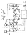
図1および図2は本発明の第1実施例を示すものであり、図1は自動二輪車用ブレーキ装置の液圧回路図、図2はタイミングチャートである。
【0011】
先ず図1において、スクータ型である自動二輪車には、乗員が右手で操作する右ブレーキレバー1の操作に応じて液圧を出力する第1マスタシリンダMAと、乗員が左手で操作する左ブレーキレバー2の操作に応じて液圧を出力する第2マスタシリンダMBとが搭載される。一方、自動二輪車の前輪には、一対のポッド3,4を有する前輪用車輪ブレーキBFが搭載されており、この前輪用車輪ブレーキBFには、第1マスタシリンダMAが制御弁手段6Aを介して接続されるとともに第2マスタシリンダMBが制御弁手段6B1および遅延弁5を介して接続される。また後輪に装着された後輪用車輪ブレーキBRには第2マスタシリンダMBが制御弁手段6B2を介して接続される。
【0012】
制御弁手段6Aは、前輪用車輪ブレーキBFのポッド3および第1マスタシリンダMA間に設けられる常開型電磁弁7と、該常開型電磁弁7に並列に接続されるチェック弁8と、前輪用車輪ブレーキBFのポッド3およびリザーバ10A間に設けられる常閉型電磁弁9とで構成されるものであり、第1マスタシリンダMAおよび前輪用車輪ブレーキBFのポッド3間の連通・遮断と、前輪用車輪ブレーキBFのポッド3およびリザーバ10A間の連通・遮断とを切換え可能である。
【0013】
リザーバ10Aには、該リザーバ10Aのブレーキ液を汲上げて第1マスタシリンダMA側に圧送する戻しポンプ11Aの吸入側が吸入弁12Aを介して接続されており、この戻しポンプ11Aの吐出側は、吐出弁13Aを介して第1マスタシリンダMAに接続される。
【0014】
制御弁手段6B1は、上記制御弁手段6Aと同様に常開型電磁弁7、チェック弁8および常閉型電磁弁9で構成されるものであり、前輪用車輪ブレーキBFのポッド4に接続される遅延弁5および第2マスタシリンダMB間の連通・遮断と、前記遅延弁5およびリザーバ10B間の連通・遮断とを切換え可能である。
【0015】
また制御弁手段6B2は、上記制御弁手段6A,6B1と同様に常開型電磁弁7、チェック弁8および常閉型電磁弁9で構成されるものであり、後輪用車輪ブレーキBRおよび第2マスタシリンダMB間の連通・遮断と、後輪用車輪ブレーキBRおよびリザーバ10B間の連通・遮断とを切換え可能である。
【0016】
リザーバ10Bには、該リザーバ10Bのブレーキ液を汲上げて第2マスタシリンダMB側に圧送する戻しポンプ11Bの吸入側が吸入弁12Bを介して接続されており、この戻しポンプ11Bの吐出側は、吐出弁13Bを介して第2マスタシリンダMBに接続される。
【0017】
前記両戻しポンプ11A,11Bには共通な単一のモータ16が連結されており、該モータ16により両戻しポンプ11A,11Bが駆動される。
【0018】
このような制御弁手段6A,6B1,6B2において、右および左ブレーキレバー1,2によるブレーキ操作時に車輪がロック状態に入りそうになったときのアンチロックブレーキ制御時には、常開型電磁弁7…のうちロック状態に入りそうである車輪に対応する常開型電磁弁を通電により閉弁するとともに常閉型電磁弁9…のうち上記車輪に対応する常閉型電磁弁を通電により開弁する。そうすると、ブレーキ液圧の一部がリザーバ10Aあるいは10Bに逃がされて減圧されることになる。またブレーキ液圧を保持する際には、常開型電磁弁7…を通電により閉弁するとともに常閉型電磁弁9…を非通電により閉弁状態に保持すればよく、ブレーキ液圧を増圧する際には、常開型電磁弁7…を非通電により開弁するとともに常閉型電磁弁9…を非通電により閉弁状態に保持すればよい。
【0019】
一対の戻しポンプ11A,11Bを共通に駆動するモータ16は、上記アンチロックブレーキ制御の開始に応じて作動を開始するものであり、リザーバ10A,10Bに逃がされたブレーキ液が戻しポンプ11A,11Bから第1および第2マスタシリンダMA,MB側に戻される。したがってリザーバ10A,10Bに逃がした分だけ第1および第2マスタシリンダMA,MBにおけるブレーキレバー1,2の操作量が増加することはない。
【0020】
各制御弁手段6A,6B1,6B2における常開型電磁弁7…および常閉型電磁弁9…の非通電・通電、ならびにモータ16の作動は、前輪および後輪の車輪速度を個別に検出する前輪用および後輪用車輪速度センサ19F,19Rの検出信号が入力される制御ユニット18により制御されるものであり、制御ユニット18は、前記車輪速度センサ19F,19Rの検出信号に基づいて車輪がロック状態に入りそうであると判断したときには、ブレーキ液圧の減・増圧サイクルを繰返すように各制御弁手段6A,6B1,6B2の作動を制御することで、前輪用および後輪用車輪ブレーキBF,BRのアンチロック制御を実行する。
【0021】
また制御ユニット18は、前記各制御弁手段6A,6B1,6B2のいずれか1つによるアンチロックブレーキ制御の開始に伴ってモータ16の作動を開始する。
【0022】
ところで、制御ユニット18は、前輪用および後輪用車輪速度センサ19F,19Rでそれぞれ検出した車輪速度に基づいて前輪および後輪の加・減速度を演算し、基本的には、前記演算加・減速度が正から負に転換したことを以って増圧制御を開始するのであるが、前輪単独制動状態での前輪用車輪ブレーキBFのアンチロック制御を実行するにあたり、前輪の演算加・減速度ACLが正の値であって前輪の演算加・減速度ACLの微分値WDDが正の設定微分値WDDO以上の状態にある範囲では、前輪の演算加・減速度ACLが正から負に転換する前であっても前輪用車輪ブレーキBFの液圧を増圧制御するようにしている。
【0023】
次にこの第1実施例の作用について説明すると、前輪の単独制動時に前輪がロック状態に陥ることを回避するために前輪用車輪ブレーキBFのアンチロック制御を実行する場合、前輪の車輪速度、前輪の演算加・減速度ACL、前輪の演算加・減速度ACLの微分値WDDが、図2で示すように変化するときに、基本的には、前輪の演算加・減速度ACLが正から負に転換する時刻t3で前輪用車輪ブレーキBFの増圧制御を開始するのであるが、その時刻t3前であっても、前輪の演算加・減速度ACLが正の値であって前輪の演算加・減速度ACLの微分値WDDが正の設定微分値WDDO以上の状態にある範囲(時刻t1〜t2の範囲)では、前輪用車輪ブレーキBFの液圧を増圧するように補正する。
【0024】
前輪の単独制動時における上述のようなアンチロック制御を実行すると、高摩擦係数の路面で前輪用車輪ブレーキBFが過減圧状態となるのを防止し、減速度に「抜け感」が生じることを回避して制動フィーリングを向上することができる。
【0025】
すなわち前輪の演算加・減速度ACLの微分値WDDは、前輪の演算加・減速度ACLの変化傾向を示すものであり、高摩擦係数の路面では前輪用車輪ブレーキBFの減圧によって前輪の車輪速度が低摩擦係数の路面に比べて速やかに回復するはずである。而して前輪の演算加・減速度ACLが正であって、その演算加・減速度ACLの微分値WDDが正の設定微分値WDDO以上となる範囲(時刻t1〜t2の範囲)を、前輪の車輪速度の急激な回復過程として定めることができ、そのような前輪の車輪速度の急激な回復過程は高摩擦係数の路面では前輪の演算加・減速度ACLが正から負に変化する時刻t3前に生じるはずであり、高摩擦係数の路面では前輪用車輪ブレーキBFを早めに増圧状態として、減速度に「抜け感」が生じることを回避し得るのである。
【0026】
一方、低摩擦係数の路面では、前輪用車輪ブレーキBFの減圧制御によって前輪の車輪速度が回復する速度は緩やかであり、前輪の演算加・減速度ACLの微分値WDDが正の設定微分値WDDO以上となることはなく、前輪の演算加・減速度ACLが正から負に変化するタイミングで増圧制御を開始するようにして、前輪用車輪ブレーキBFの減圧制御の状態を長くすることで減圧量を大きめにし、車体安定性を向上することが可能である。
【0027】
図3は本発明の第2実施例を示すものであり、制御ユニット18は、前輪の単独制動時における前輪用車輪ブレーキBFのアンチロック制御時において、前輪のスリップ率が設定スリップ率以下である状態すなわち前輪の車輪速度が設定スリップ率の基準車輪速度以上である状態であって、前輪の演算加・減速度ACLが正の設定加、減速度ACLO以上であるとともに前輪の演算加・減速度ACLの微分値WDDが負である範囲では、前輪の演算加・減速度ACLが正から負に転換する前であっても前輪用車輪ブレーキBFの液圧を増圧制御する。
【0028】
ここで、前輪の車輪速度、前輪の演算加・減速度ACL、前輪の演算加・減速度ACLの微分値WDDが、図3で示すように変化するときを想定すると、基本的には、前輪の演算加・減速度ACLが正から負に転換する時刻t3′で前輪用車輪ブレーキBFの増圧制御を開始するのであるが、その時刻t3′前であっても、前輪の演算加・減速度ACLが正の設定加、減速度ACLO以上であるとともに前輪の演算加・減速度ACLの微分値WDDが負である範囲(時刻t1′〜t2′)の範囲では、前輪用車輪ブレーキBFの液圧を増圧するように補正する。
【0029】
この第2実施例によっても、高摩擦係数の路面で前輪用車輪ブレーキBFが過減圧状態となるのを防止し、減速度に「抜け感」が生じることを回避して制動フィーリングを向上することができる。
【0030】
すなわち前輪の演算加・減速度ACLの微分値WDDは、前輪の演算加・減速度ACLの変化傾向を示すものであり、高摩擦係数の路面では前輪用車輪ブレーキBFの減圧によって前輪の車輪速度が低摩擦係数の路面に比べて速やかに回復するはずである。而して急激な回復後に車輪速度の変化が緩やかになった状態を、前輪のスリップ率が設定スリップ率以下、前輪の演算加・減速度ACLの微分値WDDが負、前輪の演算加・減速度ACLが正の設定加、減速度ACLO以上である範囲として定めることができ、その状態は、高摩擦係数の路面では前輪の演算加・減速度ACLが正から負に転換する前に生じるので、高摩擦係数の路面では前輪用車輪ブレーキBFを早めに増圧状態とし、減速度に「抜け感」が生じることを回避し得るのである。
【0031】
以上、本発明の実施例を説明したが、本発明は上記実施例に限定されるものではなく、特許請求の範囲に記載された本発明を逸脱することなく種々の設計変更を行うことが可能である。
【0032】
【発明の効果】
以上のように請求項1記載の発明によれば、高摩擦係数の路面では前輪用車輪ブレーキの減圧によって前輪の車輪速度が低摩擦係数の路面に比べて速やかに回復するので、車輪速度の急激な回復過程を検出するようにして前輪用車輪ブレーキを早めに増圧状態とし、減速度に「抜け感」が生じることを回避して制動フィーリングを向上することができる。
【0033】
また請求項2記載の発明によれば、高摩擦係数の路面では前輪用車輪ブレーキの減圧によって前輪の車輪速度が低摩擦係数の路面に比べて速やかに回復するので、急激な回復後に車輪速度の変化が緩やかになった状態を検出するようにして前輪用車輪ブレーキを早めに増圧状態とし、減速度に「抜け感」が生じることを回避して制動フィーリングを向上することができる。
【図面の簡単な説明】
【図1】第1実施例の自動二輪車用ブレーキ装置の液圧回路図である。
【図2】タイミングチャートである。
【図3】第2実施例のタイミングチャートである。
【符号の説明】
19F・・・前輪用車輪速度センサ
19R・・・後輪用車輪速度センサ
ACL・・・前輪の演算加・減速度
ACLO・・・正の設定加・減速度
BF・・・前輪用車輪ブレーキ
BR・・・後輪用車輪ブレーキ
WDD・・・前輪の演算加・減速度の微分値
WDDO・・・正の設定微分値[0001]
BACKGROUND OF THE INVENTION
The present invention calculates the acceleration / deceleration of front wheels and rear wheels based on the wheel speeds detected by the front wheel and rear wheel wheel speed sensors, respectively, and the calculated acceleration / deceleration has changed from positive to negative. Thus, the present invention relates to an antilock brake control method for a motorcycle that can execute antilock control of front and rear wheel brakes independently of each other by starting pressure increase control.
[0002]
[Prior art]
Such an antilock brake control method for a motorcycle is already well known, for example, in Japanese Patent Laid-Open No. 9-328065.
[0003]
[Problems to be solved by the invention]
By the way, when anti-locking control of front wheel brakes in motorcycles, considering the road surface with a low coefficient of friction in order to improve vehicle stability, set a large amount of pressure reduction during decompression control of front wheel brakes. It is common to do. However, the road surface with a high coefficient of friction tends to be over-depressurized, especially when the front wheels are individually braked. .
[0004]
The present invention has been made in view of such circumstances, and an object of the present invention is to provide an antilock brake control method for a motorcycle that improves the braking feeling at the time of independent braking of the front wheels.
[0005]
[Means for Solving the Problems]
In order to achieve the above object, the invention according to claim 1 calculates acceleration / deceleration of front wheels and rear wheels based on wheel speeds respectively detected by front wheel and rear wheel wheel speed sensors, and calculates them. A motorcycle that can perform anti-lock control of front and rear wheel brakes independently of each other by starting pressure increase control when the acceleration / deceleration changes from positive to negative. In the anti-lock brake control method, when performing anti-lock control of the front wheel brake in the front wheel single braking state, the front wheel calculation acceleration / deceleration has a positive value during the rapid recovery process of the front wheel speed. The front wheel calculation acceleration / deceleration differential value is defined as a range that is greater than or equal to the positive set differential value , and within that range, even before the front wheel calculation acceleration / deceleration changes from positive to negative Front wheel brake Characterized in that the Gosuru the pressure increase control of the hydraulic pressure.
[0006]
According to the first aspect of the present invention, when the anti-lock control of the front wheel brake is performed in the single brake state of the front wheel, the front wheel brake is over decompressed on the road surface having a high friction coefficient. The braking feeling can be improved by avoiding the occurrence of “missing feeling” in the deceleration. In other words, the differential value of the calculated acceleration / deceleration of the front wheels indicates the tendency of the calculated acceleration / deceleration of the front wheels to change, and on the road surface with a high friction coefficient, the front wheel speed is reduced by reducing the pressure of the front wheel brake. It should recover quickly compared to the road surface. Thus, the range in which the front wheel acceleration / deceleration is positive and the front wheel calculation acceleration / deceleration differential value is greater than or equal to the positive set differential value can be defined as a rapid recovery process of the wheel speed. Since the rapid recovery process of the front wheel speed occurs before the front wheel calculation acceleration / deceleration changes from positive to negative on the road surface with a high coefficient of friction, the front wheel brake may be in a pressure increasing state early. It can be done.
[0007]
In order to achieve the above object, the invention according to claim 2 calculates the acceleration / deceleration of the front wheels and the rear wheels based on the wheel speeds detected by the front wheel and rear wheel speed sensors, respectively. A motorcycle that can perform anti-lock control of front and rear wheel brakes independently of each other by starting pressure increase control when the computation acceleration / deceleration has changed from positive to negative. In the anti-lock brake control method, when executing anti-lock control of the front wheel brake in the front wheel single braking state, the state in which the change in the wheel speed of the front wheel becomes gentle after the rapid recovery of the front wheel speed, constant as the range differential value is a negative front wheel calculating acceleration and deceleration with the front wheel of the operational acceleration and deceleration front wheel slip ratio is equal to or less than the set slip ratio is positive setting acceleration and deceleration or , Within that range, wherein the Gosuru pressure increasing the fluid pressure in the front wheel brake even before the front wheels of the operational acceleration and deceleration is converted from positive to negative.
[0008]
According to the invention described in claim 2, when the anti-lock control of the front wheel brake is performed in the single brake state of the front wheel, the front wheel brake is over decompressed on the road surface having a high friction coefficient. The braking feeling can be improved by avoiding the occurrence of “missing feeling” in the deceleration. In other words, the differential value of the calculated acceleration / deceleration of the front wheels indicates the tendency of the calculated acceleration / deceleration of the front wheels to change, and on the road surface with a high friction coefficient, the front wheel speed is reduced by reducing the pressure of the front wheel brake. It should recover quickly compared to the road surface. Thus, after a rapid recovery, the front wheel slip rate is less than the set slip rate, the front wheel calculated acceleration / deceleration differential value is negative, and the front wheel calculated acceleration / deceleration is It can be defined as a range that is greater than or equal to the positive acceleration / deceleration, and this condition occurs before the calculated acceleration / deceleration of the front wheels changes from positive to negative on road surfaces with a high friction coefficient. The pressure can be increased as soon as possible.
[0009]
DETAILED DESCRIPTION OF THE INVENTION
DESCRIPTION OF THE PREFERRED EMBODIMENTS Embodiments of the present invention will be described below based on examples of the present invention shown in the accompanying drawings.
[0010]
1 and 2 show a first embodiment of the present invention. FIG. 1 is a hydraulic circuit diagram of a motorcycle brake device, and FIG. 2 is a timing chart.
[0011]
First, in FIG. 1, a scooter type motorcycle includes a first master cylinder MA that outputs a hydraulic pressure in response to an operation of a
[0012]
The control valve means 6A includes a normally open solenoid valve 7 provided between the
[0013]
A suction side of a
[0014]
The control valve means 6B1, like the control valve means 6A, is composed of a normally open solenoid valve 7, a
[0015]
Similarly to the control valve means 6A, 6B1, the control valve means 6B2 is composed of a normally open type electromagnetic valve 7, a
[0016]
A suction side of a
[0017]
A common
[0018]
In such control valve means 6A, 6B1, 6B2, during the anti-lock brake control when the wheel is about to enter the locked state when the right and left
[0019]
The
[0020]
The deenergization / energization of the normally open solenoid valve 7... And the normally closed
[0021]
The
[0022]
By the way, the
[0023]
Next, the operation of the first embodiment will be described. When the anti-lock control of the front wheel brake BF is executed in order to avoid the front wheel from being locked during the single braking of the front wheel, the front wheel speed, front wheel, When the calculated acceleration / deceleration ACL of the front wheel and the differential value WDD of the calculated acceleration / deceleration ACL of the front wheel change as shown in FIG. 2, basically, the calculated acceleration / deceleration ACL of the front wheel changes from positive to negative. The pressure increase control of the front wheel brake BF is started at a time t3 when the front wheel is switched to. Even before the time t3, the front wheel calculation acceleration / deceleration ACL is a positive value and the front wheel calculation acceleration is increased. In the range where the differential value WDD of the deceleration ACL is equal to or greater than the positive set differential value WDDO (range from time t1 to t2), the hydraulic pressure of the front wheel brake BF is corrected to be increased.
[0024]
When the anti-lock control as described above at the time of independent braking of the front wheel is executed, the front wheel brake BF is prevented from being over-depressurized on the road surface with a high coefficient of friction, and a “feeling of falling out” is generated in the deceleration. By avoiding the braking feeling, the braking feeling can be improved.
[0025]
In other words, the differential value WDD of the front wheel calculation acceleration / deceleration ACL indicates a change tendency of the front wheel calculation acceleration / deceleration ACL, and on the road surface with a high friction coefficient, the front wheel speed is reduced by reducing the pressure of the front wheel brake BF. Should recover quickly compared to a road surface with a low coefficient of friction. Thus, a range (a range from time t1 to t2) in which the calculated acceleration / deceleration ACL of the front wheel is positive and the differential value WDD of the calculated acceleration / deceleration ACL is greater than or equal to the positive set differential value WDDO is determined. The abrupt recovery process of the front wheel speed can be determined at a time t3 when the front wheel calculation acceleration / deceleration ACL changes from positive to negative on a road surface with a high friction coefficient. It should occur before, and on the road surface with a high coefficient of friction, the front wheel brake BF can be pre-pressurized early to avoid a “feeling of falling out” in the deceleration.
[0026]
On the other hand, on the road surface with a low friction coefficient, the speed at which the front wheel speed is recovered by the decompression control of the front wheel brake BF is moderate, and the differential value WDD of the front wheel calculation acceleration / deceleration ACL is a positive set differential value WDDO. The pressure increase control is started at the timing when the front wheel calculation acceleration / deceleration ACL changes from positive to negative, and the pressure reduction control of the front wheel brake BF is lengthened. It is possible to increase the amount and improve the vehicle stability.
[0027]
FIG. 3 shows a second embodiment of the present invention, in which the
[0028]
Here, assuming that the wheel speed of the front wheel, the calculated acceleration / deceleration ACL of the front wheel, and the differential value WDD of the calculated acceleration / deceleration ACL of the front wheel change as shown in FIG. The pressure increase control of the front wheel brake BF is started at time t3 ′ when the calculated acceleration / deceleration ACL changes from positive to negative. In the range where the speed ACL is greater than the positive setting acceleration / deceleration ACLO and the differential value WDD of the front wheel calculation acceleration / deceleration ACL is negative (time t1 'to t2'), the front wheel brake BF Correct the fluid pressure to increase.
[0029]
Also according to the second embodiment, the front wheel brake BF is prevented from being excessively depressurized on the road surface having a high friction coefficient, and the braking feeling is improved by avoiding the occurrence of a “feeling of falling out” in the deceleration. be able to.
[0030]
In other words, the differential value WDD of the front wheel calculation acceleration / deceleration ACL indicates a change tendency of the front wheel calculation acceleration / deceleration ACL, and on the road surface with a high friction coefficient, the front wheel speed is reduced by reducing the pressure of the front wheel brake BF. Should recover quickly compared to a road surface with a low coefficient of friction. Thus, after a sudden recovery, the change in the wheel speed has become gradual, the front wheel slip rate is less than the set slip rate, the front wheel operation acceleration / deceleration ACL differential value WDD is negative, and the front wheel operation addition / reduction. The speed ACL can be determined as a range where the positive acceleration / deceleration is greater than the deceleration ACLO. This condition occurs on the road surface with a high friction coefficient before the calculated acceleration / deceleration ACL of the front wheels changes from positive to negative. On the road surface with a high coefficient of friction, the front wheel brake BF is brought into a pressure increasing state early so as to avoid the occurrence of a “missing feeling” in the deceleration.
[0031]
Although the embodiments of the present invention have been described above, the present invention is not limited to the above-described embodiments, and various design changes can be made without departing from the present invention described in the claims. It is.
[0032]
【The invention's effect】
As described above, according to the first aspect of the present invention, on the road surface with a high friction coefficient, the wheel speed of the front wheel recovers more quickly than the road surface with a low friction coefficient by reducing the pressure of the front wheel brake. Therefore, the front wheel brake can be in a pressure-increasing state early so as to detect a recovery process, thereby avoiding a “feeling of falling out” in the deceleration and improving the braking feeling.
[0033]
According to the second aspect of the invention, on the road surface with a high friction coefficient, the wheel speed of the front wheel recovers more quickly than the road surface with a low friction coefficient by reducing the pressure of the front wheel brake. By detecting a state in which the change has become gradual, the front wheel brake can be brought into a pressure-increasing state early so as to avoid a “feeling of falling out” in the deceleration and improve the braking feeling.
[Brief description of the drawings]
FIG. 1 is a hydraulic circuit diagram of a motorcycle brake device according to a first embodiment.
FIG. 2 is a timing chart.
FIG. 3 is a timing chart of the second embodiment.
[Explanation of symbols]
19F: front
Claims (2)
Priority Applications (1)
| Application Number | Priority Date | Filing Date | Title |
|---|---|---|---|
| JP2001067366A JP4177559B2 (en) | 2001-03-09 | 2001-03-09 | Anti-lock brake control method for motorcycles |
Applications Claiming Priority (1)
| Application Number | Priority Date | Filing Date | Title |
|---|---|---|---|
| JP2001067366A JP4177559B2 (en) | 2001-03-09 | 2001-03-09 | Anti-lock brake control method for motorcycles |
Publications (2)
| Publication Number | Publication Date |
|---|---|
| JP2002264793A JP2002264793A (en) | 2002-09-18 |
| JP4177559B2 true JP4177559B2 (en) | 2008-11-05 |
Family
ID=18925729
Family Applications (1)
| Application Number | Title | Priority Date | Filing Date |
|---|---|---|---|
| JP2001067366A Expired - Lifetime JP4177559B2 (en) | 2001-03-09 | 2001-03-09 | Anti-lock brake control method for motorcycles |
Country Status (1)
| Country | Link |
|---|---|
| JP (1) | JP4177559B2 (en) |
Families Citing this family (1)
| Publication number | Priority date | Publication date | Assignee | Title |
|---|---|---|---|---|
| JP5335512B2 (en) * | 2009-03-26 | 2013-11-06 | 日信工業株式会社 | Brake hydraulic pressure control device for bar handle vehicle |
-
2001
- 2001-03-09 JP JP2001067366A patent/JP4177559B2/en not_active Expired - Lifetime
Also Published As
| Publication number | Publication date |
|---|---|
| JP2002264793A (en) | 2002-09-18 |
Similar Documents
| Publication | Publication Date | Title |
|---|---|---|
| JP4543484B2 (en) | Brake hydraulic pressure control device | |
| JP4177559B2 (en) | Anti-lock brake control method for motorcycles | |
| JP2844777B2 (en) | Anti-skid control device | |
| JP3913992B2 (en) | Anti-lock brake control method for motorcycles | |
| JP3914000B2 (en) | Anti-lock brake control method for motorcycles | |
| JP3620071B2 (en) | Anti-skid equipment for automobiles | |
| JP4364444B2 (en) | Method for judging friction coefficient of road surface for motorcycle | |
| JP3913993B2 (en) | Anti-lock brake control method for motorcycles | |
| JP3913994B2 (en) | Anti-lock brake control method for motorcycles | |
| JP4318973B2 (en) | Anti-lock brake control method for vehicle | |
| JP4453152B2 (en) | Starting method of braking force distribution control | |
| JP2639040B2 (en) | Brake pressure control device | |
| JP4422248B2 (en) | Anti-skid control device | |
| JP4419272B2 (en) | Anti-skid control device | |
| JP4233945B2 (en) | Anti-lock brake control device for vehicle and motorcycle | |
| JP4243011B2 (en) | Anti-lock brake control method for motorcycles | |
| JP4280586B2 (en) | Anti-lock brake control device for vehicle | |
| JP4560850B2 (en) | Brake hydraulic pressure control device | |
| JP4529229B2 (en) | Anti-skid control device | |
| JP4233959B2 (en) | Anti-lock brake control device for vehicle | |
| JP4138222B2 (en) | Front wheel brake fluid pressure control method for motorcycles | |
| JP3607318B2 (en) | Anti-skid control device for vehicle | |
| JP4586228B2 (en) | Ending method of braking force distribution control | |
| JP4421854B2 (en) | Anti-lock brake control device for vehicle | |
| KR100976223B1 (en) | A brake control method |
Legal Events
| Date | Code | Title | Description |
|---|---|---|---|
| A621 | Written request for application examination |
Free format text: JAPANESE INTERMEDIATE CODE: A621 Effective date: 20041102 |
|
| A131 | Notification of reasons for refusal |
Free format text: JAPANESE INTERMEDIATE CODE: A131 Effective date: 20060517 |
|
| A977 | Report on retrieval |
Free format text: JAPANESE INTERMEDIATE CODE: A971007 Effective date: 20060517 |
|
| A521 | Written amendment |
Free format text: JAPANESE INTERMEDIATE CODE: A523 Effective date: 20060713 |
|
| A02 | Decision of refusal |
Free format text: JAPANESE INTERMEDIATE CODE: A02 Effective date: 20070124 |
|
| A01 | Written decision to grant a patent or to grant a registration (utility model) |
Free format text: JAPANESE INTERMEDIATE CODE: A01 |
|
| A61 | First payment of annual fees (during grant procedure) |
Free format text: JAPANESE INTERMEDIATE CODE: A61 Effective date: 20080822 |
|
| FPAY | Renewal fee payment (event date is renewal date of database) |
Free format text: PAYMENT UNTIL: 20110829 Year of fee payment: 3 |
|
| R150 | Certificate of patent or registration of utility model |
Free format text: JAPANESE INTERMEDIATE CODE: R150 Ref document number: 4177559 Country of ref document: JP Free format text: JAPANESE INTERMEDIATE CODE: R150 |
|
| FPAY | Renewal fee payment (event date is renewal date of database) |
Free format text: PAYMENT UNTIL: 20120829 Year of fee payment: 4 |
|
| R250 | Receipt of annual fees |
Free format text: JAPANESE INTERMEDIATE CODE: R250 |
|
| FPAY | Renewal fee payment (event date is renewal date of database) |
Free format text: PAYMENT UNTIL: 20130829 Year of fee payment: 5 |
|
| R250 | Receipt of annual fees |
Free format text: JAPANESE INTERMEDIATE CODE: R250 |
|
| R250 | Receipt of annual fees |
Free format text: JAPANESE INTERMEDIATE CODE: R250 |
|
| R250 | Receipt of annual fees |
Free format text: JAPANESE INTERMEDIATE CODE: R250 |
|
| R250 | Receipt of annual fees |
Free format text: JAPANESE INTERMEDIATE CODE: R250 |
|
| R250 | Receipt of annual fees |
Free format text: JAPANESE INTERMEDIATE CODE: R250 |
|
| R250 | Receipt of annual fees |
Free format text: JAPANESE INTERMEDIATE CODE: R250 |
|
| R250 | Receipt of annual fees |
Free format text: JAPANESE INTERMEDIATE CODE: R250 |
|
| R250 | Receipt of annual fees |
Free format text: JAPANESE INTERMEDIATE CODE: R250 |
|
| R250 | Receipt of annual fees |
Free format text: JAPANESE INTERMEDIATE CODE: R250 |
|
| EXPY | Cancellation because of completion of term | ||
| S111 | Request for change of ownership or part of ownership |
Free format text: JAPANESE INTERMEDIATE CODE: R313111 |
|
| R370 | Written measure of declining of transfer procedure |
Free format text: JAPANESE INTERMEDIATE CODE: R370 |