JP4176408B2 - Welding method and cylindrical structure and gear pump using the welding method - Google Patents
Welding method and cylindrical structure and gear pump using the welding method Download PDFInfo
- Publication number
- JP4176408B2 JP4176408B2 JP2002217120A JP2002217120A JP4176408B2 JP 4176408 B2 JP4176408 B2 JP 4176408B2 JP 2002217120 A JP2002217120 A JP 2002217120A JP 2002217120 A JP2002217120 A JP 2002217120A JP 4176408 B2 JP4176408 B2 JP 4176408B2
- Authority
- JP
- Japan
- Prior art keywords
- welding
- deformation
- cylindrical body
- thin
- welding method
- Prior art date
- Legal status (The legal status is an assumption and is not a legal conclusion. Google has not performed a legal analysis and makes no representation as to the accuracy of the status listed.)
- Expired - Fee Related
Links
Images


Classifications
-
- F—MECHANICAL ENGINEERING; LIGHTING; HEATING; WEAPONS; BLASTING
- F04—POSITIVE - DISPLACEMENT MACHINES FOR LIQUIDS; PUMPS FOR LIQUIDS OR ELASTIC FLUIDS
- F04C—ROTARY-PISTON, OR OSCILLATING-PISTON, POSITIVE-DISPLACEMENT MACHINES FOR LIQUIDS; ROTARY-PISTON, OR OSCILLATING-PISTON, POSITIVE-DISPLACEMENT PUMPS
- F04C14/00—Control of, monitoring of, or safety arrangements for, machines, pumps or pumping installations
- F04C14/18—Control of, monitoring of, or safety arrangements for, machines, pumps or pumping installations characterised by varying the volume of the working chamber
- F04C14/22—Control of, monitoring of, or safety arrangements for, machines, pumps or pumping installations characterised by varying the volume of the working chamber by changing the eccentricity between cooperating members
-
- B—PERFORMING OPERATIONS; TRANSPORTING
- B23—MACHINE TOOLS; METAL-WORKING NOT OTHERWISE PROVIDED FOR
- B23K—SOLDERING OR UNSOLDERING; WELDING; CLADDING OR PLATING BY SOLDERING OR WELDING; CUTTING BY APPLYING HEAT LOCALLY, e.g. FLAME CUTTING; WORKING BY LASER BEAM
- B23K31/00—Processes relevant to this subclass, specially adapted for particular articles or purposes, but not covered by only one of the preceding main groups
- B23K31/02—Processes relevant to this subclass, specially adapted for particular articles or purposes, but not covered by only one of the preceding main groups relating to soldering or welding
-
- F—MECHANICAL ENGINEERING; LIGHTING; HEATING; WEAPONS; BLASTING
- F04—POSITIVE - DISPLACEMENT MACHINES FOR LIQUIDS; PUMPS FOR LIQUIDS OR ELASTIC FLUIDS
- F04C—ROTARY-PISTON, OR OSCILLATING-PISTON, POSITIVE-DISPLACEMENT MACHINES FOR LIQUIDS; ROTARY-PISTON, OR OSCILLATING-PISTON, POSITIVE-DISPLACEMENT PUMPS
- F04C15/00—Component parts, details or accessories of machines, pumps or pumping installations, not provided for in groups F04C2/00 - F04C14/00
- F04C15/0003—Sealing arrangements in rotary-piston machines or pumps
- F04C15/0007—Radial sealings for working fluid
- F04C15/0019—Radial sealing elements specially adapted for intermeshing-engagement type machines or pumps, e.g. gear machines or pumps
-
- F—MECHANICAL ENGINEERING; LIGHTING; HEATING; WEAPONS; BLASTING
- F04—POSITIVE - DISPLACEMENT MACHINES FOR LIQUIDS; PUMPS FOR LIQUIDS OR ELASTIC FLUIDS
- F04C—ROTARY-PISTON, OR OSCILLATING-PISTON, POSITIVE-DISPLACEMENT MACHINES FOR LIQUIDS; ROTARY-PISTON, OR OSCILLATING-PISTON, POSITIVE-DISPLACEMENT PUMPS
- F04C2/00—Rotary-piston machines or pumps
- F04C2/08—Rotary-piston machines or pumps of intermeshing-engagement type, i.e. with engagement of co-operating members similar to that of toothed gearing
- F04C2/10—Rotary-piston machines or pumps of intermeshing-engagement type, i.e. with engagement of co-operating members similar to that of toothed gearing of internal-axis type with the outer member having more teeth or tooth-equivalents, e.g. rollers, than the inner member
- F04C2/102—Rotary-piston machines or pumps of intermeshing-engagement type, i.e. with engagement of co-operating members similar to that of toothed gearing of internal-axis type with the outer member having more teeth or tooth-equivalents, e.g. rollers, than the inner member the two members rotating simultaneously around their respective axes
-
- B—PERFORMING OPERATIONS; TRANSPORTING
- B23—MACHINE TOOLS; METAL-WORKING NOT OTHERWISE PROVIDED FOR
- B23K—SOLDERING OR UNSOLDERING; WELDING; CLADDING OR PLATING BY SOLDERING OR WELDING; CUTTING BY APPLYING HEAT LOCALLY, e.g. FLAME CUTTING; WORKING BY LASER BEAM
- B23K2101/00—Articles made by soldering, welding or cutting
- B23K2101/04—Tubular or hollow articles
-
- Y—GENERAL TAGGING OF NEW TECHNOLOGICAL DEVELOPMENTS; GENERAL TAGGING OF CROSS-SECTIONAL TECHNOLOGIES SPANNING OVER SEVERAL SECTIONS OF THE IPC; TECHNICAL SUBJECTS COVERED BY FORMER USPC CROSS-REFERENCE ART COLLECTIONS [XRACs] AND DIGESTS
- Y10—TECHNICAL SUBJECTS COVERED BY FORMER USPC
- Y10T—TECHNICAL SUBJECTS COVERED BY FORMER US CLASSIFICATION
- Y10T29/00—Metal working
- Y10T29/49—Method of mechanical manufacture
- Y10T29/4935—Heat exchanger or boiler making
- Y10T29/49366—Sheet joined to sheet
- Y10T29/49368—Sheet joined to sheet with inserted tubes
Description
【0001】
【発明の属する技術分野】
この発明は、ギアポンプのケーシングなどを溶接する方法及びその溶接方法を使用した筒状構造体、主にギヤポンプに関するものである。
【0002】
【従来の技術】
例えば、ギアポンプPとして、特開2000−9058号公報、特開2001−80498号公報などに記載される図2乃至図4に示すものがあり、このギアポンプPは、各種機器のハウジングH内に組み込まれ、吸入ポート1からオイルaを吸引し、吐出ポート2からオイルaを吐出する。そのオイルaの吸入・吐出作用は、モータMにより回転する軸3に固定のインナーロータ4と、そのインナーロータ4に偏心してケーシング内に回転自在なアウターロータ5との噛み合いにより行い、そのインナーロータ4等から成るポンプ部を回転軸3の軸方向に複数設けている。
【0003】
そのポンプ部のケーシングは、アウターロータ5の外周面を被う周面ケーシング6と、各ポンプ部を区画するシリンダ部材7a及び両端シリンダ部材7bからなるその側面を被う側面ケーシングとから成る。その周面ケーシング6と側面ケーシング7a、7bは、ポンプ部のケーシングをなすため、密に結合する必要があり、一般には、周面ケーシング6の両側外周縁全周と側面ケーシング7a、7bの一側外周縁全周を溶接(t部分)している。
【0004】
【発明が解決しようとする課題】
上記両ケーシング6、7a、7bの全周溶接は、従来、その周囲の任意の点に溶接具Sを向け、その点から全周に亘って行うのが常である。
【0005】
しかしながら、上記ギアポンプPの周面ケーシング6には、吐出側が密になり、吸入側に十分な空隙が生じるように、アウターロータ5を一定方向に常に押圧する摺動シール(アペックスシール)8を設けており、そのシール8の装填用穴9が形成されている(図3、図4参照)。この周面ケーシング6のように、穴9などの薄肉部(切欠)が存在すると、その薄肉部は、溶接の凝縮力に対し、他の部分より抗力が弱く、変形する場合がある。
【0006】
例えば、図5に示すように、被溶接部材10(周面ケーシング6)に切欠11(穴9)が存在する場合、任意の点から溶接を全周に亘って行うと、切欠11の部分においては溶接による凝縮力bにより、曲げ応力Qが生じ、被溶接部材10は、その外形が鎖線のごとく切欠11を短軸上とする楕円形に変形する。
【0007】
一方、この種の全周溶接において、被溶接部材10は、その全周が拘束されていないため(変形可能のため)、溶接開始点cにおける溶接の凝縮力により、切欠11の存在と同様に、その溶接開始点を短軸上とする楕円形に変形する。すなわち、溶接開始点cを基準とすると、図6に示すように、周方向の各部位はサインカーブに類似した変形を行う。
【0008】
このように、被溶接部材10が変形すると、例えば、ギアポンプPの周面ケーシング6のように、アウターロータ5が装填されるものにあっては、嵌め合い精度が低下したり、嵌め合いができなくなる。
【0009】
この発明は、上記実情の下、被溶接部材10の変形を抑制することを課題とする。
【0010】
【課題を解決するための手段】
上記課題を解決するために、この発明は、上述のように薄肉部の溶接凝固と溶接開始点の溶接凝固が、同一の変形を生じさせることに着目し、その両溶接凝固による変形を相互に打ち消すようにしたのである。打ち消し合えば、筒体の原形は維持される。
【0011】
具体的には、肉厚が周囲の一部で薄肉部となっている筒体の周縁部全周をその一点から全周に亘って他の部材に溶接する際、前記薄肉部への溶接による筒体の変形を打ち消す力が発生するように、その薄肉部から周方向に離れた部位から溶接を開始することとしたのである。
【0012】
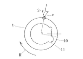
例えば、図6に示すような変形を示す被溶接部材にあっては、上記筒体の変形を打ち消す力が発生する周方向の部位を、上記薄肉部から周方向90度回った部位とする。具体的には、図1aに示すように、円筒状被溶接部材10に1つの切欠11がある場合、その切欠11から周方向90度回った( 周方向に90度離れた)部位cから溶接を開始する。なお、図中、矢印Rは被溶接部材10の回転方向を示す。また、90度回った部位とは、完全に90度回転した位置のみを意味するのではなく、溶接開始点cの溶接凝固力と切欠部の溶接凝固力が打ち消し合うことができる90度近傍の点を意味する。
【0013】
このようにすれば、溶接開始点cの溶接凝固力と切欠部の溶接凝固力が打ち消し合って、被溶接部材10は、溶接後においても、鎖線のごとくの外形を呈して原形(実線)とほぼ同一の形状を維持する。
このことから、筒体は、肉厚が周の一部で薄肉部となって、全周に亘って他の部材に溶接される筒体においては、溶接開始点での溶接凝固に伴って起きる筒体の変形によって前記薄肉部の変形を打ち消すように前記溶接開始点が周の一部に設定されているものを採用すれば、良いこととなる。このとき、図5に示すように、その溶接開始点での溶接凝固に伴って起きる筒体の変形は、通常、溶接開始点を短軸上とする楕円形への変形となる。
【0014】
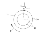
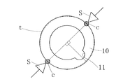
また、上記薄肉部が複数ある場合には、上記筒体の変形を打ち消す力が発生する周方向に離れた部位を、最も大きい薄肉部を基準として決定してもよいが、その各部の数や形状によって溶接開始点をずらすのが好ましい。例えば、図1bに示すように、同一大きさ(断面積)の切欠11が2つある場合には、両切欠11、11の中点部位から周方向90度回って切欠11から離れた部位cから溶接を開始し、図1cに示すように、同一大きさの切欠11が等間隔で3つある場合には、中央の切欠11から周方向90度回って切欠11から離れた部位cから溶接を開始する。
【0015】
これらは、切欠11が、同一大きさ及び等間隔の場合であったが、切欠11の大きさや切欠11の間隔が異なる場合には、溶接開始点cの溶接凝固力と切欠部の溶接凝固力のバランスを考えて溶接開始点cを調整することが好ましい。
【0016】
例えば、図1dに示すように、切欠の大きさが異なる場合、2つの切欠の中点よりも大きい切欠側の方に移動させた位置から90度回って切欠11と異なる部位cから溶接を開始し、図1eに示すように、3つの同一の大きさの切欠11、11、11の間隔が1:2の場合、両端にある切欠の中点よりも狭い間隔がある方に移動させた位置から90度回って切欠11と異なる部位cから溶接を開始する。
【0017】
被溶接部材10の筒状断面形状は、円筒に限らず、三角、四角、六角などの多角形、及びそれら多角形が正多角形の場合、楕円形なども採用できる。また、全周に亘って均一厚み(均一肉厚)のものに限らず、肉厚が切欠11から周方向に徐々に厚く又は薄くなるもの(徐々に肉薄又は肉厚となるもの)も採用し得る。この肉厚が変化するものにおいては、その肉厚を考慮して、溶接開始点cを決定する。例えば、切欠11から周方向に徐々に肉厚となる場合には、上記図1aなどの場合より、切欠11側に近づける。
【0018】
なお、上述の溶接方法において、溶接部全周等間隔にスポット溶接した後、この発明の溶接方法を採用することもできる。また、図1fに示すように、切欠11などの基準点の両側周囲二方向(周方向の正逆二方向)に回って切欠11と異なる部位から、溶接を開始することもできる。さらに、被溶接物の回転速度(溶接速度)、回転方向Rは、被溶接物の形状などを考慮し、実験などによって適宜に決定する。
【0019】
これらの溶接方法は、筒体と他の部材とを一体化する筒状構造体、例えば、上述のギアポンプPの周面ケーシング6の両側周側縁全周を両側面ケーシング7a、7bの周縁に溶接する場合などに使用する。
【0020】
【実施の形態】
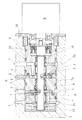
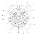
図2乃至図4に示すギアポンプPの周面ケーシング6と側面ケーシング(シリンダ部材)7a、7bの周縁溶接にこの発明の溶接方法を使用した。そのギアポンプPは、上述のように、ポンプ部を2つ有し、その両ポンプ部は位相が180度異なっている。すなわち、図3に示す態様が中心軸に対し相互に逆となっている。図3中、6aはケーシング6、シリンダ7a、7bに挿し通されてそれらを位置決めするピンである。
【0021】
そのポンプ部は、回転軸3に固定のインナーロータ4及びアウターロータ5と、その周りの周面ケーシング6及びシリンダ部材7a、7bとから成り、モータMにより回転軸3が回転し、それに伴って、前述と同様に、インナーロータ4とアウターロータ5が回転し、オイルaを、吸入ポート1から吸込み、吐出ポート2から吐出する。図中、15は板ばね、16はシールであり、詳細は上述の公開公報を参照。
【0022】
このギアポンプPにおいて、周面ケーシング6と側面ケーシング(シリンダ部材)7a、7bの側縁全周(t部分)を、図1bの態様に基づき、レーザ溶接したところ、周面ケーシング6の変形は殆んどなく、周面ケーシング6はアウターロータ5と高い嵌め合い精度を得ることができた。
【0023】
【発明の効果】
この発明は、以上のように、溶接開始点の選択により、被溶接部材の変形を抑制したので、精密圧入部品や嵌め合い部品、密封部品などの全周溶接に有効である。
【図面の簡単な説明】
【図1a】この発明の一実施形態の概念図
【図1b】同他の実施形態の概念図
【図1c】同他の実施形態の概念図
【図1d】同他の実施形態の概念図
【図1e】同他の実施形態の概念図
【図1f】同他の実施形態の概念図
【図2】この発明を採用したギアポンプの要部切断正面図
【図3】同要部切断側面図
【図4】図3のX−X線要部切断正面図
【図5】従来例の概念図
【図6】筒体全周溶接における周方向の部材と歪の関係図
【符号の説明】
P ギアポンプ
a オイル
t 溶接部
4 インナーロータ
5 アウターロータ
6 周面ケーシング
7a、7b 側面ケーシング(シリンダ部材)
10 被溶接部材(筒体)
11 切欠[0001]
BACKGROUND OF THE INVENTION
The present invention relates to a method for welding a casing of a gear pump and the like, a cylindrical structure using the welding method, and mainly a gear pump.
[0002]
[Prior art]
For example, there is a gear pump P shown in FIGS. 2 to 4 described in Japanese Patent Laid-Open No. 2000-9058 and Japanese Patent Laid-Open No. 2001-80498. The gear pump P is incorporated in a housing H of various devices. Then, the oil a is sucked from the
[0003]
The casing of the pump portion includes a
[0004]
[Problems to be solved by the invention]
Conventionally, all-around welding of the
[0005]
However, the
[0006]
For example, as shown in FIG. 5, when a notch 11 (hole 9) exists in the member to be welded 10 (circumferential casing 6), if welding is performed over an entire circumference from an arbitrary point, The bending force Q is generated by the condensing force b due to welding, and the
[0007]
On the other hand, in this kind of all-around welding, since the entire circumference of the
[0008]
In this way, when the member to be welded 10 is deformed, for example, in the case where the
[0009]
This invention makes it a subject to suppress the deformation | transformation of the to-be-welded
[0010]
[Means for Solving the Problems]
In order to solve the above-described problems, the present invention focuses on the fact that the weld solidification of the thin-walled portion and the weld solidification of the welding start point cause the same deformation as described above, and the deformation caused by the two weld solidifications is mutually performed. I tried to cancel it out. If they cancel each other, the original shape of the cylinder is maintained.
[0011]
Specifically, when the thickness is welded to another member over the entire circumference of the periphery entire circumference of the cylindrical body has a thin portion in part of the periphery from that single point, by welding to the thin portion In order to generate a force that cancels the deformation of the cylindrical body, welding is started from a portion away from the thin portion in the circumferential direction.
[0012]
For example, in a member to be welded that shows deformation as shown in FIG. 6, a circumferential portion where a force that cancels the deformation of the cylinder is generated is a portion rotated 90 degrees in the circumferential direction from the thin portion. Specifically, as shown in FIG. 1a, when there is one
[0013]
In this way, the weld solidification force at the welding start point c and the weld solidification force at the notch portion cancel each other, and the
Therefore, the tubular body is a thin portion wall thickness in part of the peripheral, in the cylindrical body to be welded to another member over the entire circumference, it occurs with the weld solidification at the welding start point If the welding start point is set to a part of the circumference so as to cancel the deformation of the thin wall portion by the deformation of the cylindrical body, it is good. At this time, as shown in FIG. 5, the deformation of the cylindrical body accompanying the welding solidification at the welding start point is usually an elliptical shape having the welding start point on the short axis.
[0014]
Further, when there are a plurality of the thin portions, the circumferentially separated portion where the force for canceling the deformation of the cylindrical body may be determined based on the largest thin portion. It is preferable to shift the welding start point depending on the shape. For example, as shown in FIG. 1b, when there are two
[0015]
These are cases where the
[0016]
For example, as shown in FIG. 1d, when the size of the notch is different, welding is started from a part c different from the
[0017]
The cylindrical cross-sectional shape of the member to be welded 10 is not limited to a cylinder, and a polygon such as a triangle, a square, or a hexagon, and an elliptical shape when the polygon is a regular polygon can also be employed. Further, not only those having a uniform thickness (uniform thickness) over the entire circumference, but also those whose thickness gradually increases or decreases in the circumferential direction from the notch 11 (those that gradually become thinner or thicker ) are adopted. obtain. In the case where the thickness changes, the welding start point c is determined in consideration of the thickness. For example, when the thickness gradually increases from the
[0018]
In the above-described welding method, after the spot welding is performed at equal intervals around the entire welded portion, the welding method of the present invention can be employed. Further, as shown in FIG. 1 f, welding can be started from a part different from the
[0019]
These methods of welding tubular structure integrating the cylindrical body and another member, for example, both side peripheral edges all around the
[0020]
Embodiment
The welding method of the present invention was used for the peripheral welding of the
[0021]
The pump part is composed of an
[0022]
In this gear pump P, when the
[0023]
【The invention's effect】
As described above, since the deformation of the member to be welded is suppressed by selecting the welding start point, the present invention is effective for all-around welding of precision press-fitting parts, fitting parts, sealing parts, and the like.
[Brief description of the drawings]
FIG. 1a is a conceptual diagram of an embodiment of the present invention. FIG. 1b is a conceptual diagram of another embodiment. FIG. 1c is a conceptual diagram of the other embodiment. FIG. 1d is a conceptual diagram of the other embodiment. FIG. 1e is a conceptual diagram of the other embodiment. FIG. 1f is a conceptual diagram of the other embodiment. FIG. 2 is a cutaway front view of the main part of the gear pump adopting the present invention. FIG. 4 is a cutaway front view of the main part of line XX in FIG. 3. FIG. 5 is a conceptual diagram of a conventional example. FIG.
P Gear pump a Oil t Welded
10 Welded member (cylinder)
11 Notch
Claims (10)
上記周面ケーシング(6)の両側周側縁(t)全周を、請求項1乃至5のいずれかに記載の溶接方法により、両側面ケーシング(7a、7b)の周縁(t)に溶接することを特徴とするギアポンプ(P)のケーシング溶接方法。An inner rotor (4) and an outer rotor (5) are housed inside the casing, and the casing covers the outer peripheral surface of the outer rotor (5), the outer casing (6), the outer rotor (5), and the inner rotor. In the gear pump (P) comprising the side casings (7a, 7b) covering both side surfaces of (4),
The entire circumference of both side peripheral edges (t) of the peripheral casing (6) is welded to the peripheral edges (t) of the double casings (7a, 7b) by the welding method according to any one of claims 1 to 5. A casing welding method for a gear pump (P), wherein:
Priority Applications (3)
| Application Number | Priority Date | Filing Date | Title |
|---|---|---|---|
| JP2002217120A JP4176408B2 (en) | 2002-07-25 | 2002-07-25 | Welding method and cylindrical structure and gear pump using the welding method |
| US10/625,541 US7124930B2 (en) | 2002-07-25 | 2003-07-24 | Welding method and tubular member and gear pump made using the welding method |
| DE10333815A DE10333815B4 (en) | 2002-07-25 | 2003-07-24 | Welding process for tubular element and gear pump, which is manufactured by the welding process |
Applications Claiming Priority (1)
| Application Number | Priority Date | Filing Date | Title |
|---|---|---|---|
| JP2002217120A JP4176408B2 (en) | 2002-07-25 | 2002-07-25 | Welding method and cylindrical structure and gear pump using the welding method |
Publications (3)
| Publication Number | Publication Date |
|---|---|
| JP2004058078A JP2004058078A (en) | 2004-02-26 |
| JP2004058078A5 JP2004058078A5 (en) | 2005-10-20 |
| JP4176408B2 true JP4176408B2 (en) | 2008-11-05 |
Family
ID=31938687
Family Applications (1)
| Application Number | Title | Priority Date | Filing Date |
|---|---|---|---|
| JP2002217120A Expired - Fee Related JP4176408B2 (en) | 2002-07-25 | 2002-07-25 | Welding method and cylindrical structure and gear pump using the welding method |
Country Status (3)
| Country | Link |
|---|---|
| US (1) | US7124930B2 (en) |
| JP (1) | JP4176408B2 (en) |
| DE (1) | DE10333815B4 (en) |
Families Citing this family (7)
| Publication number | Priority date | Publication date | Assignee | Title |
|---|---|---|---|---|
| US7530647B2 (en) * | 2005-11-01 | 2009-05-12 | Advics Co., Ltd. | Vehicular brake device |
| DE102009045227A1 (en) * | 2009-10-01 | 2011-04-21 | Robert Bosch Gmbh | Internal gear pump for a hydraulic vehicle brake system |
| JP5493758B2 (en) * | 2009-11-19 | 2014-05-14 | 株式会社アドヴィックス | Rotary pump device and vehicle brake device including the same |
| DE102012210938A1 (en) * | 2012-06-27 | 2014-05-15 | Robert Bosch Gmbh | Internal gear pump |
| JP5987524B2 (en) | 2012-07-24 | 2016-09-07 | 株式会社アドヴィックス | Gear pump device |
| JP2015105647A (en) * | 2013-12-02 | 2015-06-08 | 株式会社山田製作所 | Oil pump |
| JP6622860B1 (en) * | 2018-06-20 | 2019-12-18 | 本田技研工業株式会社 | Catalytic converter |
Family Cites Families (12)
| Publication number | Priority date | Publication date | Assignee | Title |
|---|---|---|---|---|
| US1846368A (en) * | 1929-05-13 | 1932-02-23 | Cecil R Smith | Method of making pipe |
| CH328680A (en) * | 1953-03-28 | 1958-03-31 | Pfistershammer Josef | Structure with hollow bars forming a framework |
| US4140204A (en) * | 1977-08-01 | 1979-02-20 | Gator Products, Inc. | Two-tube muffler and method of manufacture |
| US4202484A (en) * | 1978-11-20 | 1980-05-13 | Conoco, Inc. | Compression prestressed weld joints |
| US4477010A (en) * | 1981-05-27 | 1984-10-16 | Lucas Industries Limited | Method of producing a metal tube and flange assembly |
| US4590652A (en) * | 1983-10-14 | 1986-05-27 | Apx Group Inc. | Method for fabricating an air gap pipe |
| US5150520A (en) * | 1989-12-14 | 1992-09-29 | The Allen Group Inc. | Heat exchanger and method of assembly thereof |
| US5290974A (en) * | 1993-03-12 | 1994-03-01 | Arvin Industries, Inc. | Tab and notch locator for exhaust systems |
| US5464240A (en) * | 1994-01-31 | 1995-11-07 | Genesis Composites, L.C. | Hollow shell frames for bicycles and other human-powered vehicles and method for making same |
| JP2000009058A (en) | 1998-06-23 | 2000-01-11 | Denso Corp | Pump and brake device |
| JP3899785B2 (en) | 1999-07-09 | 2007-03-28 | 株式会社デンソー | Brake device for vehicle |
| JP3799599B2 (en) | 2001-02-26 | 2006-07-19 | 株式会社デンソー | Welding apparatus and welding method |
-
2002
- 2002-07-25 JP JP2002217120A patent/JP4176408B2/en not_active Expired - Fee Related
-
2003
- 2003-07-24 DE DE10333815A patent/DE10333815B4/en not_active Expired - Fee Related
- 2003-07-24 US US10/625,541 patent/US7124930B2/en not_active Expired - Fee Related
Also Published As
| Publication number | Publication date |
|---|---|
| US7124930B2 (en) | 2006-10-24 |
| DE10333815B4 (en) | 2008-01-10 |
| US20040238505A1 (en) | 2004-12-02 |
| JP2004058078A (en) | 2004-02-26 |
| DE10333815A1 (en) | 2004-03-25 |
Similar Documents
| Publication | Publication Date | Title |
|---|---|---|
| JP4176408B2 (en) | Welding method and cylindrical structure and gear pump using the welding method | |
| JP2022164746A (en) | Connection structure and hydraulic transmission | |
| JP5297756B2 (en) | Gear transmission | |
| JP2010133266A (en) | Bearing device for supercharger | |
| JP2004058078A5 (en) | ||
| JP5798882B2 (en) | Gear transmission | |
| JP6080300B2 (en) | Manufacturing method of gear pump and inner rotor | |
| JP4207974B2 (en) | Variable compression ratio internal combustion engine | |
| JP2008115820A (en) | Oil pump | |
| JP6723652B2 (en) | Gear device | |
| WO2017077948A1 (en) | Fuel pump | |
| JP6369274B2 (en) | Inscribed mesh planetary gear mechanism | |
| JP4494885B2 (en) | Scroll type fluid machine | |
| JPS614882A (en) | Gear pump | |
| WO2016117316A1 (en) | Fuel pump and manufacturing method thereof | |
| JP6951265B2 (en) | Gear device | |
| JP2017040253A (en) | Oil pump | |
| JP7360260B2 (en) | Decelerator | |
| JP2002089659A (en) | Epicyclic gear | |
| JP2007298004A (en) | Variable compression ratio internal combustion engine | |
| JP2018162676A (en) | Gear pump and tooth form creation method of outer rotor | |
| JP2009174547A (en) | Assembling method of rotating device, and tool | |
| KR101851537B1 (en) | Fuel pump | |
| JP6500455B2 (en) | Fuel pump | |
| JP2001263262A (en) | Internal gear pump |
Legal Events
| Date | Code | Title | Description |
|---|---|---|---|
| A521 | Request for written amendment filed |
Free format text: JAPANESE INTERMEDIATE CODE: A523 Effective date: 20050701 |
|
| A621 | Written request for application examination |
Free format text: JAPANESE INTERMEDIATE CODE: A621 Effective date: 20050701 |
|
| A977 | Report on retrieval |
Free format text: JAPANESE INTERMEDIATE CODE: A971007 Effective date: 20071107 |
|
| A131 | Notification of reasons for refusal |
Free format text: JAPANESE INTERMEDIATE CODE: A131 Effective date: 20071113 |
|
| A521 | Request for written amendment filed |
Free format text: JAPANESE INTERMEDIATE CODE: A523 Effective date: 20080115 |
|
| A131 | Notification of reasons for refusal |
Free format text: JAPANESE INTERMEDIATE CODE: A131 Effective date: 20080212 |
|
| A521 | Request for written amendment filed |
Free format text: JAPANESE INTERMEDIATE CODE: A523 Effective date: 20080411 |
|
| A131 | Notification of reasons for refusal |
Free format text: JAPANESE INTERMEDIATE CODE: A131 Effective date: 20080520 |
|
| A521 | Request for written amendment filed |
Free format text: JAPANESE INTERMEDIATE CODE: A523 Effective date: 20080707 |
|
| TRDD | Decision of grant or rejection written | ||
| A01 | Written decision to grant a patent or to grant a registration (utility model) |
Free format text: JAPANESE INTERMEDIATE CODE: A01 Effective date: 20080819 |
|
| A01 | Written decision to grant a patent or to grant a registration (utility model) |
Free format text: JAPANESE INTERMEDIATE CODE: A01 |
|
| A61 | First payment of annual fees (during grant procedure) |
Free format text: JAPANESE INTERMEDIATE CODE: A61 Effective date: 20080820 |
|
| FPAY | Renewal fee payment (event date is renewal date of database) |
Free format text: PAYMENT UNTIL: 20110829 Year of fee payment: 3 |
|
| R150 | Certificate of patent or registration of utility model |
Free format text: JAPANESE INTERMEDIATE CODE: R150 |
|
| FPAY | Renewal fee payment (event date is renewal date of database) |
Free format text: PAYMENT UNTIL: 20110829 Year of fee payment: 3 |
|
| FPAY | Renewal fee payment (event date is renewal date of database) |
Free format text: PAYMENT UNTIL: 20120829 Year of fee payment: 4 |
|
| FPAY | Renewal fee payment (event date is renewal date of database) |
Free format text: PAYMENT UNTIL: 20120829 Year of fee payment: 4 |
|
| FPAY | Renewal fee payment (event date is renewal date of database) |
Free format text: PAYMENT UNTIL: 20130829 Year of fee payment: 5 |
|
| R250 | Receipt of annual fees |
Free format text: JAPANESE INTERMEDIATE CODE: R250 |
|
| R250 | Receipt of annual fees |
Free format text: JAPANESE INTERMEDIATE CODE: R250 |
|
| S111 | Request for change of ownership or part of ownership |
Free format text: JAPANESE INTERMEDIATE CODE: R313117 |
|
| R350 | Written notification of registration of transfer |
Free format text: JAPANESE INTERMEDIATE CODE: R350 |
|
| LAPS | Cancellation because of no payment of annual fees |