JP4172967B2 - Inkjet recording device - Google Patents
Inkjet recording device Download PDFInfo
- Publication number
- JP4172967B2 JP4172967B2 JP2002237353A JP2002237353A JP4172967B2 JP 4172967 B2 JP4172967 B2 JP 4172967B2 JP 2002237353 A JP2002237353 A JP 2002237353A JP 2002237353 A JP2002237353 A JP 2002237353A JP 4172967 B2 JP4172967 B2 JP 4172967B2
- Authority
- JP
- Japan
- Prior art keywords
- waste ink
- receiving member
- absorber
- waste
- ink
- Prior art date
- Legal status (The legal status is an assumption and is not a legal conclusion. Google has not performed a legal analysis and makes no representation as to the accuracy of the status listed.)
- Expired - Fee Related
Links
Images


Description
【0001】
【発明の属する技術分野】
本発明は、インクジェットプリンタなどのインクジェット記録装置に係り、詳しくは廃インク吸収体を備えたインクジェット記録装置に関する。
【0002】
【従来の技術】
プリンタ等のインクジェット記録装置では、記録ヘッド上のインクが乾燥して固着したり、記録ヘッドの吐出口に異物が付着したりする場合がある。このようなことが原因となって、インクの吐出不良が生じる場合がある。そのため、固着インクや異物の除去を目的に記録ヘッドからインクを空吐出させたり、強制的に吸引したりする方法が採用されている。排出された廃インクは所定の場所に貯留される。
インクの強制排出を行う技術としては例えば、特開2000−85142公報や特開平8−332738号公報がある。特開2000−85142公報では、ヘッドのインク吐出状態を初期の吐出状態に回復させるため、インクを吐出するノズルからインクを強制的に吸引している。吸引したインクは複数の空間を有する廃インクタンクに貯留される。特開平8−332738号公報では、記録ヘッドから廃インクを吸引し、廃インク容器内に充填された充填材料により捕集する。
【0003】
【発明が解決しようとする課題】
ところで、特開2000−85142公報の廃インクタンクには複数の空間が構成されるので、タンクが大型化するのは否めない。このため、廃インクタンクを内蔵させる装置内のレイアウトを考えた場合には、設計の自由度の低さが問題になる。また、特開平8−332738号公報では、インクが満杯になったときは廃インク収納部を交換することが前提となっているため、一つのインク吸収体しか備えられていない。そのため、交換作業が頻繁になるという問題が生じる。
そこで、本発明は、上述の問題点を解決するためになされたもので、装置設計の自由度を向上させると共に廃インク吸収体の交換作業を行わずに多くの廃インクを空吐出できるインクジェット記録装置を提供することを目的とする。
【0004】
【課題を解決するための手段】
上記の課題を解決するため、本発明に係るインクジェット記録装置は、
インクを吐出するノズルを有する複数の記録ヘッドを搭載したキャリッジを走査して画像を形成するインクジェット記録装置において、
前記キャリッジの走査方向の一端部側には前記記録ヘッドから空吐出された廃インクを受ける第1廃インク受け部材を含む前記記録ヘッドの維持回復機構が配置され、前記キャリッジの走査方向の他端部側には前記記録ヘッドから空吐出された廃インクを受ける第2廃インク受け部材が配置され、
前記第1廃インク受け部材は前記複数の記録ヘッドのうちの一部の記録ヘッドのノズルが納まる大きさの開口を有し、前記第2廃インク受け部材は前記複数の記録ヘッドのノズルが納まる大きさの開口を有し、
更に、前記維持回復機構で生じる前記廃インクを吸収する第1廃インク吸収体と、前記第2廃インク受け部材で受ける廃インクを吸収する前記第1廃インク吸収体よりも容量の小さな第2廃インク吸収体とを有するとともに、前記第1、第2廃インク吸収体のそれぞれについて廃インク量が規定量に達したことを検出する検出手段を備え、
前記第2廃インク受け部材に対しては複数の記録ヘッドから空吐出を行い、前記第1廃インク受け部材に対しては複数の記録ヘッドから複数回に分けて空吐出を行い、
前記第1、第2廃インク吸収体のいずれもが規定量に達していないときには、前記第1、第2廃インク受け部材のいずれかに対して空吐出を行うとともに、前記第1、第2廃インク吸収体のいずれかが規定量に達したときには、他方の廃インク受け部材に対して空吐出を行う
構成とした。
【0005】
【発明の実施の形態】
以下、図面により本発明の実施の形態を詳細に説明する。図1〜図3は本発明の実施の形態を示すインクジェット記録装置100の正面断面図である。図4はインクジェット記録装置100の外観斜視図であり、図5は同装置の側部断面図である。なお、インクジェット記録装置の構成に関しては、まず、図1〜図3を用いて説明し、これに続いて図4及び図5によって残りの構成について説明する。
インクジェット記録装置100は記録ヘッド101、102によってインクを吐出して被記録材上に画像を形成する装置である。記録ヘッド101、102がそのインク滴吐出方向を下方に向けて装着されたキャリッジ13は本体左右の側板間に横架された主ガイドロッド11によってキャリッジ13の主走査方向(主ガイドロッド11の軸方向)に摺動自在に保持されている。記録ヘッド101、102はイエロー、マゼンタ、シアン、ブラックのインクを吐出する4個のノズル103、104、105、106を有している。
因みに、記録ヘッド101、102として用いるインクジェットヘッドは圧電素子などの電気機械変換素子で液室(インク流路)壁面を形成する振動板を介してインクを加圧するピエゾ型のもの、あるいは発熱抵抗体による膜沸騰でバブルを生じさせてインクを加圧するバブル型のもの、若しくはインク流路壁面を形成する振動板とこれに対向する電極との間の静電力で振動板を変位させてインクを加圧する静電型のものなどを使用することができるが、本実施の形態では静電型インクジェットヘッドを用いている。
【0006】
各ノズル103、104、105、106へは後述するサブタンク12から各色のインクが供給される。ノズル103、104、105、106に付着したインクは乾燥して固着することがあるので、装置本体には、ノズル103、104、105、106の保湿を目的としてキャップ107、108が取付固定されており、印字待機中においてはノズル103、104、105、106がキャップ107、108の正面に位置してノズル先端部を塞ぐようになっている。
また、インクジェット記録装置100では、記録ヘッド101、102からインクを空吐出することで記録ヘッドの吐出口に付着した乾燥インクや異物を強制的に除去する機能を有しており、空吐出された廃インクが貯留される2つの廃インク吸収部111a、115aを備えている。図1において、廃インク吸収部111aはその内部にこの例では、白色もしくはそれに近い淡い色のポリウレタンを主材料とした廃インク吸収体111を備え、上部には上方に伸びる筒状の廃インク受け部材110を有し、装置中央の下側に配設されている。
【0007】
廃インク吸収部115aは廃インク吸収部111aよりも小さく構成され、図中左端に配されている。内部には、廃インク吸収部111aと同様の材質の廃インク吸収体115を備え、上部には筒状の廃インク受け部材114を有している。廃インク受け部材114は廃インク受け部材110に比べて太く形成されており、図2のように記録ヘッド101、102に固定されたノズル103、104、105、106が納まる程度の口径となっている。廃インク受け部材110は図3のように2つのノズル103、104又はノズル105、106が納まる程度の太さである。廃インク吸収部(廃インク吸収体)の大きさ、配設位置、筒状部材の太さ、個数は本体の空きスペースに応じて決定されたものであり、特に大きさや配置場所はインクジェット記録装置100特有のものである。
空吐出された廃インクは廃インク吸収体111、115に吸収保持されるが、廃インク吸収体111、115の規定量を超えた場合には、廃インクが漏れ出してしまう。そのため、規定量、つまり、廃インクで満タンになったことを検出するために、後述する反射型フォトセンサを用いた検出手段112、113が本体内部に取付固定されている。
【0008】
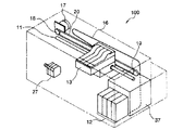
ここで、図4、図5によりインクジェット記録装置100の他の機構部について説明する。なお、図4、図5においては、廃インク吸収部111a、115aの図示は省略する。図4において、サブタンク12には交換可能な4種のインクカートリッジが装着され、そのインクがインク供給チューブ16によってノズル103、104、105、106(図1)に供給されるようになっている。また、キャップ107、108は上述したように、ノズル103、104、105、106のインクが乾燥するのを防ぐためのもので、これは、図4における信頼性維持回復機構37が有する機能の一つとなっている。この他に、信頼性維持回復機構37の信頼性維持回復動作としてはメニスカス振動を発生させる制御も行うことができる。
主ガイドロッド11上をスライドするキャリッジ13はステッピングモータからなる主走査モータ17で回転される駆動プーリ18と従動プーリ19との間に張装したタイミングベルト20に連結して、主走査モータ17を駆動制御することによってキャリッジ13、即ち記録ヘッド101、102が主走査方向に移動されるようにしている。
そして、ステッピングモータからなる副走査モータ27(図4)によって図5の給紙ローラ21と、静電搬送ベルト29が張架された搬送駆動ローラ24及び搬送従動ローラ24aを駆動する。図5において画像を形成するまでの工程を簡単に説明すると、給紙カセット4内の記録用紙3は給紙ローラ21によって搬送され、チャージャ30による静電搬送ベルト29の帯電によって記録用紙3を吸着したまま搬送し、画像形成位置まで運ばれる。そして、キャリッジ13に配設された記録ヘッド101、102(図1)によって記録用紙3上にインクのドットによる画像が形成される。その後、記録用紙3は排紙コロ33を経て排紙トレイ6に排出される。
【0009】
続いて、インクジェット記録装置100の制御回路について説明する。図6はインクジェット記録装置100の制御系のブロック図である。インクジェット記録装置100はCPU500を有し、検出手段112、113、主走査モータ動作指令回路506、空吐出指令回路503、不揮発性メモリ501、表示部502による信号の入出力を制御している。
CPU500は空吐出指令回路503に空吐出の指令を行い、これによって、空吐出指令回路503から記録ヘッド101、102に出力信号が与えられ、インクの吐出が行われる。また、CPU500は、主走査モータ動作指令回路506に対して、モータ回転の指令を行うことによって、主走査モータ動作指令回路506からの出力信号が主走査モータドライバ507を介して主走査モータ17に与えられ、主走査モータ17が回転し、キャリッジ13(図1)が主走査方向に移動される。
検出手段112、113の出力信号はCPU500に与えられ、CPU500はその出力信号から廃インク吸収体111、115による廃インクの吸収状況を判定する。不揮発性メモリ501には記録ヘッド101、102が空吐出を実行する位置、廃インク吸収体111、115の容量、廃インクの吸収状態などの情報を保持する記憶手段であり、装置の電源が遮断された場合であってもデータ内容は保持される。表示部502は図示しないLCDやLED等によって構成され、CPU500からの指令により装置の状態を、操作者に知らしめる役割を持つ。
【0010】
次に、インクジェット記録装置100の動作についてフローチャートを用いて説明する。図7はキャリッジ13が図3のように移動し、記録ヘッド101、102のノズル103〜106が廃インク吸収部111aに対して空吐出を行う場合の動作フローを示す。この場合、廃インク吸収部111aの廃インク受け部材110の太さは記録ヘッド一つ分(ノズル2つ分)にしか対応していないので、2つの記録ヘッド101、102の空吐出動作を2回に分けて実行する。
まず、最初に空吐出を行う記録ヘッド101のノズル105、106を廃インク受け部材110の開口部分に対向する位置まで移動させる(ステップS1)。次に、ステップS2で移動が完了したか否かを確認し、移動が完了していればステップS3に移り、完了していなければ再度移動完了の確認を行う。ステップS3では記録ヘッド101のノズル105、106の空吐出動作を行う。次に、ステップS4で空吐出動作が完了したか否かを確認し、完了していなければ再度空吐出動作の完了を確認する。空吐出動作が完了していることを確認した場合はステップS5に移る。
ステップS5では全ての記録ヘッド101、102(ノズル103〜106)の空吐出が完了したか否かを確認し、完了していなければステップS6に移って、次に(2番目に)空吐出を行う記録ヘッド102のノズル103、104を廃インク受け部材110の開口部分に対向する位置まで移動させてステップS2に移る。全ての記録ヘッド101、102の空吐出が完了していることを確認した場合は、ステップS7に移り、記録ヘッド101、102をキャップ107、108の位置まで戻してステップS8に移る。ステップS8では記録ヘッド101、102の移動が完了したか否かを確認して、完了していなければ再度移動完了確認を行う。移動が完了していることを確認した場合は、ステップS9で動作を終了する。
【0011】
次に、全ての記録ヘッド101、102の全てのノズル103〜106から一度に空吐出を行う場合の動作フローについて図8を用いて説明する。まず、図2のように、空吐出を行う記録ヘッド101、102のノズル103〜106を廃インク吸収体115aの廃インク受け部材114の開口部分に対向する位置まで移動させる(ステップS11)。次に、ステップS12で移動が完了したか否かを確認し、移動が完了していればステップS13に移り、完了していなければ再度移動完了の確認を行う。
ステップS13では記録ヘッド101、102のノズル103〜106の空吐出動作を行う。次に、ステップS14で空吐出動作が完了したか否かを確認し、完了していなければ再度空吐出動作の完了を確認する。空吐出動作が完了していることを確認した場合はステップS15に移る。ステップS15では記録ヘッド101、102をキャップ107、108の位置まで戻す。そして、ステップS16に移り、記録ヘッド101、102の移動が完了したか否かを確認して、完了していなければ再度移動完了確認を行う。移動が完了していることを確認した場合は、ステップS17で動作を終了する。
ここで、複数の廃インク吸収体111、115の中から使用する廃インク吸収体を選択するときの動作を説明するにあたり、まず、検出手段112、113の検出原理について図9及び図10を用いて簡単に説明する。図9及び図10は検出手段として検出手段112、廃インク吸収体として廃インク吸収体111を使用した例である。
【0012】
図9に示すように、検出手段112はそれぞれ発光部301と受光部302を備え、発光部301からは光を発光し、反射した光を受光部301が受光する。図9の例は、斜線で示した廃インクが廃インク吸収体111にまだ十分に吸収されず、廃インク吸収体111が白色もしくはそれに近い淡い色のままであるために、発光部301から照射された光が廃インク吸収体111の上面で反射し受光部302に入射される。これにより、検出手段112は未検出信号をCPU500(図6)へ出力する。
図10では、廃インク吸収体111に吸収された廃インクが検出手段112の発光部301の照射領域まで達しているため、照射された光は廃インク吸収体111の上面で反射されず受光部302に入射されない。これにより、検出手段112は廃インク検出信号をCPU500(図6)に出力し、廃インクが規定量に達したと判断する。この例のように、廃インク吸収体111の廃インクが規定量に達した場合は、インクが漏れ出すのを防ぐために、廃インク吸収体111に対する廃インクの空吐出動作を中止し、廃インク吸収体115に対してのみ空吐出動作を実行するようになっている。
【0013】
ところで、インクジェット記録装置100では、廃インクの量が規定量に達していない廃インク吸収体の内で容量の大きい廃インク吸収体から順に使用するモードと、被記録材への印字要求がない場合に廃インクの量が規定量に達していない廃インク吸収体の内で記録ヘッドからの廃インクの空吐出を記録ヘッドの印字動作における駆動領域に近い廃インク吸収体に対して行うモードと、廃インクの量が規定量に達していない廃インク吸収体の内でユーザの指定する廃インク吸収体から順に使用するモードを実行させる機能を有しており、ユーザによるモードの指定ができるようになっている。
これらのモードでは、条件に応じて、複数の廃インク吸収体111、115の中から使用する廃インク吸収体が選択される。各モードにおける動作について図11〜図13のフローチャートを用いて以下に説明する。図11は廃インクの量が規定量に達していない廃インク吸収体の内、容量の大きい廃インク吸収体から順に使用する場合のフローチャートを示している。まず、不揮発性メモリ501の情報に基づいて、最も容量の大きい廃インク吸収体を選択する(ステップS21)。次に、選択された廃インク吸収体の廃インクが規定量に達しているか否かを確認し、規定量に達していなければステップS24に移り、規定量に達していれば、ステップS23に移る。ステップS23では、次に容量の大きい廃インク吸収体を選択する。選択した廃インク吸収体をステップS24で使用した後は、ステップS25で動作を終了する。
【0014】
図12は、印字要求がある場合に、廃インクの量が規定量に達していない廃インク吸収体の内、記録ヘッドの印字駆動領域に近い廃インク吸収体に対して記録ヘッドからの空吐出を行うようにすることで、空吐出をしながらでも効率のよい印字動作ができるようにしたものである。図12に示すように、まず、最も印字効率がよくなる廃インク吸収体を選択する(ステップS31)。次に、選択された廃インク吸収体の廃インクが規定量に達しているか否かを確認し、規定量に達していなければステップS34に移り、規定量に達していれば、ステップS33に移る。ステップS33では、次に印字効率がよくなる廃インク吸収体を選択する。選択した廃インク吸収体をステップS34で使用した後は、ステップS35で動作を終了する。
図13は、廃インクの量が規定量に達していない廃インク吸収体の内、ユーザの指定する廃インク吸収体から順に使用する場合のフローチャートを示している。まず、ユーザが廃インク吸収体を選択する(ステップS41)。次に、選択された廃インク吸収体の廃インクが規定量に達しているか否かを確認し、規定量に達していなければステップS44に移り、規定量に達していれば、ステップS43に移る。ステップS43では、次に希望する廃インク吸収体を選択する。選択した廃インク吸収体をステップS44で使用した後は、ステップ45で動作を終了する。なお、インクジェット記録装置100では、全ての廃インク吸収体の廃インクが規定量に達している場合は、表示部502(図6)にその旨を表示し、廃インク吸収体の交換を促すメッセージを表示するようになっている。
【0015】
このように構成されたインクジェット記録装置100では、複数の廃インク吸収体全てが検出手段を備えているので、装置内の空きスペースに応じて廃インク吸収体を配設することが可能であり、また、廃インクが規定量に達していない廃インク吸収体だけを選択して使用することが可能である。したがって、装置設計の自由度を向上させるという効果と、廃インク吸収体の交換をしないまま多くの廃インクを空吐出できるという効果を同時に実現することができる。
また、最も大きい容量の廃インク吸収体から使用することができるので、たとえ、使用可能な廃インク吸収体が残っている状態で使用済みの廃インク吸収体を交換することがあっても、容量が大きい分だけ交換周期が長くなり、ユーザによる廃インク吸収体の交換作業を軽減することができる。
また、印字要求がある場合であっても、記録ヘッドからの空吐出を記録ヘッドの印字駆動領域に近い廃インク吸収体に対して行うことができるので、空吐出をしながらでも効率のよい印字動作が実現できる。また、ユーザの指定する廃インク吸収体から順に使用することができるので、ユーザ固有の使用環境や使用条件に合わせて使用することができる。
また、最大容量の廃インク吸収体から順に使用するか、印字要求がある場合に記録ヘッドの印字駆動領域に近い廃インク吸収体に対して記録ヘッドからの空吐出を行うか、ユーザの指定する廃インク吸収体から順に使用するかをユーザが指定することができるので、使用環境や使用条件に応じて適切な使用形態で廃インクの処理をすることができる。
なお、この例では、大きさ、形状、配設位置が異なる2個の廃インク吸収体を使用した場合を説明したが、廃インク吸収体の大きさ、配設位置、筒状部材の太さ、個数は本体の空きスペースに応じて自由に決定されるものであり、限定されるものではない。
【0016】
【発明の効果】
以上説明したように、本発明に係るインクジェット記録装置によれば、キャリッジの走査方向の一端部側には記録ヘッドから空吐出された廃インクを受ける第1廃インク受け部材を含む記録ヘッドの維持回復機構が配置され、キャリッジの走査方向の他端部側には記録ヘッドから空吐出された廃インクを受ける第2廃インク受け部材が配置され、第1廃インク受け部材は複数の記録ヘッドのうちの一部の記録ヘッドのノズルが納まる大きさの開口を有し、第2廃インク受け部材は複数の記録ヘッドのノズルが納まる大きさの開口を有し、更に、維持回復機構で生じる廃インクを吸収する第1廃インク吸収体と、第2廃インク受け部材で受ける廃インクを吸収する第1廃インク吸収体よりも容量の小さな第2廃インク吸収体とを有するとともに、第1、第2廃インク吸収体のそれぞれについて廃インク量が規定量に達したことを検出する検出手段を備え、第2廃インク受け部材に対しては複数の記録ヘッドから空吐出を行い、第1廃インク受け部材に対しては複数の記録ヘッドから複数回に分けて空吐出を行い、第1、第2廃インク吸収体のいずれもが規定量に達していないときには、第1、第2廃インク受け部材のいずれかに対して空吐出を行うとともに、第1、第2廃インク吸収体のいずれかが規定量に達したときには、他方の廃インク受け部材に対して空吐出を行う構成としたので、廃インク吸収体の交換作業をしないまま多くの廃インクを空吐出することができるとともに、空吐出しながらでも効率のよい印字動作が実現できる。
【図面の簡単な説明】
【図1】インクジェット記録装置100の正面図である。
【図2】廃インク吸収部115aに空吐出する場合のインクジェット記録装置100の正面図である。
【図3】廃インク吸収部111aに空吐出する場合のインクジェット記録装置100の正面図である。
【図4】インクジェット記録装置100の斜視図である。
【図5】インクジェット記録装置100の側面図である。
【図6】インクジェット記録装置100の制御回路を示すブロック図である。
【図7】廃インク吸収部111aに対して空吐出を行う場合のフローチャートである。
【図8】廃インク吸収部115aに対して空吐出を行う場合のフローチャートである。
【図9】検出手段112が廃インクを検出しない場合を示す図である。
【図10】検出手段112が廃インクを検出した場合を示す図である。
【図11】廃インクの量が規定量に達していない廃インク吸収体の内で容量の大きい廃インク吸収体から順に使用する場合を示すフローチャートである。
【図12】印字要求がある場合に、廃インクの量が規定量に達していない廃インク吸収体の内で記録ヘッドの印字駆動領域に近い廃インク吸収体に対して記録ヘッドからの空吐出を行う場合を示すフローチャートである。
【図13】廃インクの量が規定量に達していない廃インク吸収体の内でユーザの指定する廃インク吸収体から順に使用する場合を示すフローチャートである。
【符号の説明】
3 用紙、4 給紙カセット、6 排紙トレイ、11 主ガイドロッド、12サブタンク、13 キャリッジ、16 インク供給チューブ、17 主走査モータ、18 駆動プーリ、19 従動プーリ、20 タイミングベルト、21 給紙ローラ、24 搬送駆動ローラ、24a 搬送従動ローラ、27 副走査モータ、29 静電搬送ベルト、30 チャージャ、33 排紙コロ、37 信頼性維持回復機構、100 インクジェット記録装置、101、102 記録ヘッド、103、104、105、106 ノズル、107、108 キャップ、110、114 廃インク受け部材、111、115 廃インク吸収体、111a、115a 廃インク吸収部、112、113 検出手段、301 発光部、302 受光部、500 CPU、501 不揮発性メモリ、502 表示部、503 空吐出指令回路、506 主走査モータ動作指令回路、507 主走査モータドライバ[0001]
BACKGROUND OF THE INVENTION
The present invention relates to an ink jet recording apparatus such as an ink jet printer, and more particularly to an ink jet recording apparatus provided with a waste ink absorber.
[0002]
[Prior art]
In an ink jet recording apparatus such as a printer, the ink on the recording head may be dried and fixed, or a foreign substance may adhere to the ejection port of the recording head. This may cause ink ejection failure. For this reason, a method is employed in which ink is ejected from the recording head for the purpose of removing fixed ink or foreign matter or forcibly sucked. The discharged waste ink is stored in a predetermined place.
Examples of techniques for forcibly discharging ink include Japanese Patent Laid-Open No. 2000-85142 and Japanese Patent Laid-Open No. 8-332327. In Japanese Patent Laid-Open No. 2000-85142, in order to restore the ink ejection state of the head to the initial ejection state, ink is forcibly sucked from the nozzles that eject ink. The sucked ink is stored in a waste ink tank having a plurality of spaces. In JP-A-8-332738, waste ink is sucked from a recording head and collected by a filling material filled in a waste ink container.
[0003]
[Problems to be solved by the invention]
Incidentally, since a plurality of spaces are formed in the waste ink tank disclosed in Japanese Patent Laid-Open No. 2000-85142, it cannot be denied that the tank increases in size. For this reason, when considering the layout in the apparatus in which the waste ink tank is incorporated, the low degree of freedom in design becomes a problem. Japanese Patent Laid-Open No. 8-332738 is based on the premise that the waste ink storage section is replaced when the ink is full, and therefore, only one ink absorber is provided. Therefore, the problem that replacement work becomes frequent arises.
Accordingly, the present invention has been made to solve the above-described problems, and improves the degree of freedom in apparatus design and can perform ink jet recording that allows a large amount of waste ink to be discharged without replacing the waste ink absorber. An object is to provide an apparatus.
[0004]
[Means for Solving the Problems]
In order to solve the above problems, an ink jet recording apparatus according to the present invention includes:
In the ink jet recording apparatus which forms an image by scanning a carriage having a plurality of record heads having a nozzle that discharges ink,
A recording head maintenance / recovery mechanism including a first waste ink receiving member that receives waste ink ejected from the recording head is disposed on one end side in the scanning direction of the carriage, and the other end of the carriage in the scanning direction is disposed. A second waste ink receiving member that receives waste ink that is idly ejected from the recording head is disposed on the part side,
The first waste ink receiving member has an opening large enough to accommodate the nozzles of some of the plurality of recording heads, and the second waste ink receiving member accommodates the nozzles of the plurality of recording heads. Having an opening of a size,
Furthermore, a first waste ink absorber that absorbs the waste ink generated by the maintenance and recovery mechanism, and a second that has a smaller capacity than the first waste ink absorber that absorbs the waste ink received by the second waste ink receiving member. which has a waste ink absorber, comprising the first, detection hand stage waste ink amount for each of the second waste ink absorber is detected that has reached a prescribed amount,
For the second waste ink receiving member, idle ejection is performed from a plurality of recording heads, and for the first waste ink receiving member, idle ejection is performed in multiple times from a plurality of recording heads,
When neither of the first and second waste ink absorbers has reached the specified amount, the first and second waste ink receiving members are idled and the first and second waste ink absorbers are discharged. When any one of the waste ink absorbers reaches a specified amount, the other waste ink receiving member is ejected idle.
The configuration.
[0005]
DETAILED DESCRIPTION OF THE INVENTION
Hereinafter, embodiments of the present invention will be described in detail with reference to the drawings. 1 to 3 are front sectional views of an ink
The ink
Incidentally, the ink-jet head used as the
[0006]
Each
Further, the
[0007]
The waste
The waste ink discharged in an idle state is absorbed and held by the waste ink absorbers 111 and 115. However, if the specified amount of the waste ink absorbers 111 and 115 is exceeded, the waste ink leaks out. For this reason, detection means 112 and 113 using a reflection type photosensor, which will be described later, are attached and fixed inside the main body in order to detect that the prescribed amount, that is, the waste ink is full.
[0008]
Here, another mechanism part of the ink
A
5 is driven by the sub-scanning motor 27 (FIG. 4), which is a stepping motor, and the transport driving roller 24 and the transport driven roller 24a on which the electrostatic transport belt 29 is stretched. The process up to image formation in FIG. 5 will be described briefly. The recording paper 3 in the paper feeding cassette 4 is conveyed by the
[0009]
Next, the control circuit of the
The
The output signals of the detection means 112 and 113 are given to the
[0010]
Next, the operation of the
First, the
In step S5, it is confirmed whether or not the idle ejection of all the recording heads 101 and 102 (
[0011]
Next, an operation flow in the case where idle ejection is performed at once from all the
In step S13, the idle ejection operation of the
Here, in describing the operation when selecting the waste ink absorber to be used from among the plurality of
[0012]
As shown in FIG. 9, each of the detection means 112 includes a
In FIG. 10, since the waste ink absorbed by the
[0013]
By the way, in the ink
In these modes, a waste ink absorber to be used is selected from the plurality of
[0014]
FIG. 12 is a diagram showing an example in which, when there is a print request, among the waste ink absorbers for which the amount of waste ink has not reached the specified amount, idle discharge from the print head to the waste ink absorber near the print drive area of the print head By performing the above, it is possible to perform an efficient printing operation even during idle ejection. As shown in FIG. 12, first, a waste ink absorber that provides the best printing efficiency is selected (step S31). Next, it is confirmed whether or not the waste ink of the selected waste ink absorber has reached a specified amount. If the specified amount has not been reached, the process proceeds to step S34. If the specified amount has been reached, the process proceeds to step S33. . In step S33, a waste ink absorber that provides the next highest printing efficiency is selected. After the selected waste ink absorber is used in step S34, the operation is terminated in step S35.
FIG. 13 shows a flowchart in the case of using the waste ink absorbers designated by the user in order from the waste ink absorbers whose waste ink amount has not reached the specified amount. First, the user selects a waste ink absorber (step S41). Next, it is confirmed whether or not the waste ink of the selected waste ink absorber has reached a specified amount. If the specified amount has not been reached, the process proceeds to step S44. If the specified amount has been reached, the process proceeds to step S43. . In step S43, the desired waste ink absorber is selected next. After the selected waste ink absorber is used in step S44, the operation is terminated in step 45. In the
[0015]
In the ink
In addition, since it can be used from the waste ink absorber with the largest capacity, even if the used waste ink absorber is replaced while the usable waste ink absorber remains, the capacity Therefore, the replacement period becomes longer by the amount of the increase, and the replacement work of the waste ink absorber by the user can be reduced.
In addition, even when there is a print request, empty discharge from the recording head can be performed on the waste ink absorber close to the print drive area of the recording head, so efficient printing is possible even while empty discharge is performed. Operation can be realized. Moreover, since it can be used in order from the waste ink absorber designated by the user, it can be used in accordance with the usage environment and usage conditions unique to the user.
Also, the user designates whether the waste ink absorber is used in order from the maximum capacity waste ink, or when the print request is made, the waste ink absorber close to the print drive area of the print head is discharged from the print head. Since the user can specify whether to use the waste ink absorber in order, the waste ink can be processed in an appropriate usage form according to the use environment and use conditions.
In this example, the case where two waste ink absorbers having different sizes, shapes, and arrangement positions are used has been described. However, the size, arrangement position, and thickness of the cylindrical member of the waste ink absorber are described. The number is freely determined according to the free space of the main body and is not limited.
[0016]
【The invention's effect】
As described above, according to the ink jet recording apparatus according to the present invention, the maintenance of the recording head including the first waste ink receiving member that receives the waste ink ejected from the recording head at one end in the scanning direction of the carriage. A recovery mechanism is disposed, and a second waste ink receiving member that receives waste ink ejected from the recording head is disposed on the other end side in the scanning direction of the carriage. The first waste ink receiving member is a plurality of recording heads. The second waste ink receiving member has an opening large enough to accommodate the nozzles of a plurality of recording heads, and the waste generated by the maintenance / recovery mechanism. A first waste ink absorber that absorbs ink and a second waste ink absorber that has a smaller capacity than the first waste ink absorber that absorbs waste ink received by the second waste ink receiving member First, the waste ink amount for each of the second waste ink absorber comprising a detection means to detect that has reached a specified amount, performs idle discharge from a plurality of recording heads for the second waste ink receiving member The first waste ink receiving member is discharged in a plurality of times from a plurality of recording heads, and when neither of the first and second waste ink absorbers has reached the specified amount, the first, When either one of the first and second waste ink absorbers reaches a specified amount, the other waste ink receiving member is discharged idly. With this configuration, a large amount of waste ink can be discharged in an empty manner without replacing the waste ink absorber, and an efficient printing operation can be realized even during the empty discharge.
[Brief description of the drawings]
FIG. 1 is a front view of an ink jet recording apparatus.
FIG. 2 is a front view of the ink
FIG. 3 is a front view of the ink
4 is a perspective view of the
5 is a side view of the ink
6 is a block diagram showing a control circuit of the
FIG. 7 is a flowchart in a case where idle ejection is performed with respect to the waste
FIG. 8 is a flowchart in a case where idle ejection is performed with respect to the waste
FIG. 9 is a diagram illustrating a case where the
FIG. 10 is a diagram illustrating a case where the
FIG. 11 is a flowchart showing a case where waste ink absorbers that have not reached the specified amount are used in order from a waste ink absorber having a larger capacity.
FIG. 12 shows an empty discharge from the recording head to a waste ink absorber close to the print drive area of the recording head among the waste ink absorbers whose waste ink amount has not reached the specified amount when there is a print request. It is a flowchart which shows the case where it performs.
FIG. 13 is a flowchart illustrating a case where waste ink absorbers that have not reached a specified amount are used in order from a waste ink absorber designated by a user.
[Explanation of symbols]
3 paper, 4 paper cassette, 6 paper discharge tray, 11 main guide rod, 12 sub tank, 13 carriage, 16 ink supply tube, 17 main scanning motor, 18 driving pulley, 19 driven pulley, 20 timing belt, 21 paper feeding roller , 24 transport drive roller, 24a transport driven roller, 27 sub-scanning motor, 29 electrostatic transport belt, 30 charger, 33 paper discharge roller, 37 reliability maintenance recovery mechanism, 100 ink jet recording apparatus, 101, 102 recording head, 103, 104, 105, 106 Nozzle, 107, 108 Cap, 110, 114 Waste ink receiving member, 111, 115 Waste ink absorber, 111a, 115a Waste ink absorption part, 112, 113 detection means, 301 Light emitting part, 302 Light receiving part, 500 CPU, 501 nonvolatile memory, 502 table 503, empty discharge command circuit, 506 main scanning motor operation command circuit, 507 main scanning motor driver
Claims (1)
前記キャリッジの走査方向の一端部側には前記記録ヘッドから空吐出された廃インクを受ける第1廃インク受け部材を含む前記記録ヘッドの維持回復機構が配置され、前記キャリッジの走査方向の他端部側には前記記録ヘッドから空吐出された廃インクを受ける第2廃インク受け部材が配置され、
前記第1廃インク受け部材は前記複数の記録ヘッドのうちの一部の記録ヘッドのノズルが納まる大きさの開口を有し、前記第2廃インク受け部材は前記複数の記録ヘッドのノズルが納まる大きさの開口を有し、
更に、前記維持回復機構で生じる前記廃インクを吸収する第1廃インク吸収体と、前記第2廃インク受け部材で受ける廃インクを吸収する前記第1廃インク吸収体よりも容量の小さな第2廃インク吸収体とを有するとともに、前記第1、第2廃インク吸収体のそれぞれについて廃インク量が規定量に達したことを検出する検出手段を備え、
前記第2廃インク受け部材に対しては複数の記録ヘッドから空吐出を行い、前記第1廃インク受け部材に対しては複数の記録ヘッドから複数回に分けて空吐出を行い、
前記第1、第2廃インク吸収体のいずれもが規定量に達していないときには、前記第1、第2廃インク受け部材のいずれかに対して空吐出を行うとともに、前記第1、第2廃インク吸収体のいずれかが規定量に達したときには、他方の廃インク受け部材に対して空吐出を行う
ことを特徴とするインクジェット記録装置。 In the ink jet recording apparatus which forms an image by scanning a carriage having a plurality of record heads having a nozzle that discharges ink,
A recording head maintenance / recovery mechanism including a first waste ink receiving member that receives waste ink ejected from the recording head is disposed on one end side in the scanning direction of the carriage, and the other end of the carriage in the scanning direction. A second waste ink receiving member that receives waste ink ejected from the recording head is disposed on the side of the recording head,
The first waste ink receiving member has an opening large enough to accommodate the nozzles of some of the plurality of recording heads, and the second waste ink receiving member accommodates the nozzles of the plurality of recording heads. Having an opening of a size,
Further, a first waste ink absorber that absorbs the waste ink generated by the maintenance and recovery mechanism, and a second capacity that is smaller than the first waste ink absorber that absorbs the waste ink received by the second waste ink receiving member. which has a waste ink absorber, comprising the first, detection hand stage waste ink amount for each of the second waste ink absorber is detected that has reached a prescribed amount,
For the second waste ink receiving member, idle ejection is performed from a plurality of recording heads, and for the first waste ink receiving member, idle ejection is performed in multiple times from a plurality of recording heads,
When neither of the first and second waste ink absorbers has reached the specified amount, the first and second waste ink receiving members are idle-discharged and the first and second waste ink absorbers are discharged. The ink jet recording apparatus characterized in that when any one of the waste ink absorbers reaches a specified amount, the other waste ink receiving member is ejected idly.
Priority Applications (1)
| Application Number | Priority Date | Filing Date | Title |
|---|---|---|---|
| JP2002237353A JP4172967B2 (en) | 2002-08-16 | 2002-08-16 | Inkjet recording device |
Applications Claiming Priority (1)
| Application Number | Priority Date | Filing Date | Title |
|---|---|---|---|
| JP2002237353A JP4172967B2 (en) | 2002-08-16 | 2002-08-16 | Inkjet recording device |
Publications (2)
| Publication Number | Publication Date |
|---|---|
| JP2004074556A JP2004074556A (en) | 2004-03-11 |
| JP4172967B2 true JP4172967B2 (en) | 2008-10-29 |
Family
ID=32021135
Family Applications (1)
| Application Number | Title | Priority Date | Filing Date |
|---|---|---|---|
| JP2002237353A Expired - Fee Related JP4172967B2 (en) | 2002-08-16 | 2002-08-16 | Inkjet recording device |
Country Status (1)
| Country | Link |
|---|---|
| JP (1) | JP4172967B2 (en) |
Families Citing this family (4)
| Publication number | Priority date | Publication date | Assignee | Title |
|---|---|---|---|---|
| JP5510313B2 (en) * | 2010-12-28 | 2014-06-04 | ブラザー工業株式会社 | Inkjet recording device |
| JP6142615B2 (en) * | 2013-03-27 | 2017-06-07 | セイコーエプソン株式会社 | Printing device |
| JP6801221B2 (en) * | 2016-05-12 | 2020-12-16 | 株式会社リコー | Liquid discharge device |
| JP6904714B2 (en) * | 2017-01-16 | 2021-07-21 | 理想科学工業株式会社 | Inkjet printing equipment |
-
2002
- 2002-08-16 JP JP2002237353A patent/JP4172967B2/en not_active Expired - Fee Related
Also Published As
| Publication number | Publication date |
|---|---|
| JP2004074556A (en) | 2004-03-11 |
Similar Documents
| Publication | Publication Date | Title |
|---|---|---|
| US7562961B2 (en) | Droplet discharging apparatus, image forming apparatus and preliminary discharge method | |
| JP5171068B2 (en) | Inkjet recording device | |
| EP2460660B1 (en) | Image forming apparatus | |
| JP2007136807A (en) | Ink supplying mechanism and inkjet recorder comprising the same | |
| JP4245411B2 (en) | Image forming apparatus | |
| JP4762001B2 (en) | Apparatus for ejecting liquid droplets and image forming apparatus | |
| JP2010000671A (en) | Ink cartridge and image forming device | |
| JP4841217B2 (en) | Image forming apparatus | |
| JP3933660B2 (en) | Image forming apparatus | |
| JP4172967B2 (en) | Inkjet recording device | |
| JP2007313654A (en) | Inkjet printer | |
| JP5754621B2 (en) | Image forming apparatus | |
| JP2003019816A (en) | Printer | |
| JP5121583B2 (en) | Droplet ejection device, image forming apparatus | |
| JP3887985B2 (en) | Inkjet printer | |
| US6672703B2 (en) | Inkjet printing apparatus and printing system | |
| JP2001026123A (en) | Ink jet recorder | |
| JP4163464B2 (en) | Inkjet recording device | |
| JP2004066553A (en) | Inkjet recorder | |
| JP5440147B2 (en) | Image forming apparatus, pump control method, and program | |
| JP2004066554A (en) | Inkjet recorder | |
| JP4651081B2 (en) | Recording apparatus and control method of recording apparatus | |
| JP2007098914A (en) | Image forming device | |
| JP2004330517A (en) | Image formation device | |
| JP2011104820A (en) | Ink jet recording device |
Legal Events
| Date | Code | Title | Description |
|---|---|---|---|
| A621 | Written request for application examination |
Free format text: JAPANESE INTERMEDIATE CODE: A621 Effective date: 20050811 |
|
| RD02 | Notification of acceptance of power of attorney |
Free format text: JAPANESE INTERMEDIATE CODE: A7422 Effective date: 20050916 |
|
| A977 | Report on retrieval |
Free format text: JAPANESE INTERMEDIATE CODE: A971007 Effective date: 20080228 |
|
| A131 | Notification of reasons for refusal |
Free format text: JAPANESE INTERMEDIATE CODE: A131 Effective date: 20080304 |
|
| A521 | Written amendment |
Free format text: JAPANESE INTERMEDIATE CODE: A523 Effective date: 20080428 |
|
| TRDD | Decision of grant or rejection written | ||
| A01 | Written decision to grant a patent or to grant a registration (utility model) |
Free format text: JAPANESE INTERMEDIATE CODE: A01 Effective date: 20080812 |
|
| A01 | Written decision to grant a patent or to grant a registration (utility model) |
Free format text: JAPANESE INTERMEDIATE CODE: A01 |
|
| A61 | First payment of annual fees (during grant procedure) |
Free format text: JAPANESE INTERMEDIATE CODE: A61 Effective date: 20080812 |
|
| R150 | Certificate of patent or registration of utility model |
Free format text: JAPANESE INTERMEDIATE CODE: R150 |
|
| FPAY | Renewal fee payment (event date is renewal date of database) |
Free format text: PAYMENT UNTIL: 20110822 Year of fee payment: 3 |
|
| FPAY | Renewal fee payment (event date is renewal date of database) |
Free format text: PAYMENT UNTIL: 20110822 Year of fee payment: 3 |
|
| FPAY | Renewal fee payment (event date is renewal date of database) |
Free format text: PAYMENT UNTIL: 20120822 Year of fee payment: 4 |
|
| FPAY | Renewal fee payment (event date is renewal date of database) |
Free format text: PAYMENT UNTIL: 20120822 Year of fee payment: 4 |
|
| FPAY | Renewal fee payment (event date is renewal date of database) |
Free format text: PAYMENT UNTIL: 20130822 Year of fee payment: 5 |
|
| LAPS | Cancellation because of no payment of annual fees |