JP4170262B2 - Biological information measuring device and standard element - Google Patents
Biological information measuring device and standard element Download PDFInfo
- Publication number
- JP4170262B2 JP4170262B2 JP2004172101A JP2004172101A JP4170262B2 JP 4170262 B2 JP4170262 B2 JP 4170262B2 JP 2004172101 A JP2004172101 A JP 2004172101A JP 2004172101 A JP2004172101 A JP 2004172101A JP 4170262 B2 JP4170262 B2 JP 4170262B2
- Authority
- JP
- Japan
- Prior art keywords
- light
- optical element
- light guide
- living body
- biometric
- Prior art date
- Legal status (The legal status is an assumption and is not a legal conclusion. Google has not performed a legal analysis and makes no representation as to the accuracy of the status listed.)
- Expired - Fee Related
Links
Images


Classifications
-
- A—HUMAN NECESSITIES
- A61—MEDICAL OR VETERINARY SCIENCE; HYGIENE
- A61B—DIAGNOSIS; SURGERY; IDENTIFICATION
- A61B5/00—Measuring for diagnostic purposes; Identification of persons
- A61B5/145—Measuring characteristics of blood in vivo, e.g. gas concentration, pH value; Measuring characteristics of body fluids or tissues, e.g. interstitial fluid, cerebral tissue
- A61B5/1495—Calibrating or testing of in-vivo probes
-
- A—HUMAN NECESSITIES
- A61—MEDICAL OR VETERINARY SCIENCE; HYGIENE
- A61B—DIAGNOSIS; SURGERY; IDENTIFICATION
- A61B5/00—Measuring for diagnostic purposes; Identification of persons
- A61B5/145—Measuring characteristics of blood in vivo, e.g. gas concentration, pH value; Measuring characteristics of body fluids or tissues, e.g. interstitial fluid, cerebral tissue
- A61B5/14532—Measuring characteristics of blood in vivo, e.g. gas concentration, pH value; Measuring characteristics of body fluids or tissues, e.g. interstitial fluid, cerebral tissue for measuring glucose, e.g. by tissue impedance measurement
-
- A—HUMAN NECESSITIES
- A61—MEDICAL OR VETERINARY SCIENCE; HYGIENE
- A61B—DIAGNOSIS; SURGERY; IDENTIFICATION
- A61B5/00—Measuring for diagnostic purposes; Identification of persons
- A61B5/145—Measuring characteristics of blood in vivo, e.g. gas concentration, pH value; Measuring characteristics of body fluids or tissues, e.g. interstitial fluid, cerebral tissue
- A61B5/1455—Measuring characteristics of blood in vivo, e.g. gas concentration, pH value; Measuring characteristics of body fluids or tissues, e.g. interstitial fluid, cerebral tissue using optical sensors, e.g. spectral photometrical oximeters
-
- A—HUMAN NECESSITIES
- A61—MEDICAL OR VETERINARY SCIENCE; HYGIENE
- A61B—DIAGNOSIS; SURGERY; IDENTIFICATION
- A61B2560/00—Constructional details of operational features of apparatus; Accessories for medical measuring apparatus
- A61B2560/02—Operational features
- A61B2560/0223—Operational features of calibration, e.g. protocols for calibrating sensors
- A61B2560/0228—Operational features of calibration, e.g. protocols for calibrating sensors using calibration standards
- A61B2560/0233—Optical standards
Description
本発明は、生体組織を光学的に測定することによって体液中のグルコース、コレステロール、尿素、トリグリセリド等を非侵襲的に測定するために使用する生体情報測定装置及び標準素子に関する。 The present invention relates to biological tissue glucose in body fluid by measuring optically, cholesterol, urea, the biological information measuring device and a standard element is used to measure the triglyceride or the like non-invasively.
従来から、生体や溶液中の特定成分を測定する際に、種々の生体情報測定装置やキャリブレーション方法が提案されている。 Conventionally, when measuring a specific component in a living body or a solution, various biological information measuring devices and calibration methods have been proposed.
例えば、特許文献1によると、近赤外光を用いて、生体表面に配置された光源から生体内部に入射した光のうち、生体内部で散乱、吸収されながら伝播して再び生体表面に現れた光を受光することで生体内部の情報を計測している。
For example, according to
この場合、光源や検出器の性能が経年的に変化した場合、測定値が変化し測定精度が悪くなるという課題を有していた。 In this case, when the performance of the light source or the detector changes with time, there is a problem that the measurement value changes and the measurement accuracy deteriorates.
そこで、光源から出射した光を対向する保護カバーに設けられた反射体に照射させ、反射した光を、光源と同一面上にある受光部で受光して、光の光量を計測し、校正値として、測定値を補正していた。
しかしながら、上記のような従来の光学測定方法および光学測定装置では、以下のような問題点を有していた。 However, the conventional optical measurement method and optical measurement apparatus as described above have the following problems.
従来の方法では、保護カバーにつけた反射板に、光源から出射した光を照射して、反射板から反射した光を、光源と同一平面内に設けた受光部より検出するものである。 In the conventional method, light emitted from a light source is irradiated onto a reflection plate attached to a protective cover, and light reflected from the reflection plate is detected by a light receiving unit provided in the same plane as the light source.
したがって、光源と受光部が同一平面にあって、しかもそれらと対向する位置に反射板が設定する場合には有効であるが、生体に向けて光を出射する出射部と生体からの光が入射する入射部とが同一面にない場合には、反射板に光を照射するとともに、反射板からの反射光を受光することは非常に困難であった。 Therefore, it is effective when the light source and the light receiving unit are in the same plane and the reflector is set at a position facing them, but the light emitting unit that emits light toward the living body and the light from the living body enter. When the incident part is not on the same plane, it is very difficult to irradiate the reflecting plate with light and receive the reflected light from the reflecting plate.
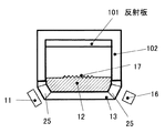
図4に、光学測定装置に反射板を適用した場合の図を示す。すなわち、図4の光学測定装置は、光源11、生体測定用光学素子12、保持台13、光検出器16から構成されている。また、カバー102の開口部とは反対側に反射板101が設けられている。
FIG. 4 shows a diagram when a reflector is applied to the optical measuring device. That is, the optical measurement apparatus of FIG. 4 includes a
保持台13は、生体測定用光学素子12を保持する保持台であり、光源11から出射した光を生体測定用光学素子12に入射させ、生体測定用光学素子12から出射する光を光検出器16に出射する穴部25が設けられている。生体測定用光学素子12に設けられた溝部17は、生体に向けて光を出射する出射部と生体からの光が入射する入射部とを含んでおり、それらの同一面に配置されておらず、出射部から出射した光は直接入射部に入射するような溝形状となっている。従って、出射部から出射した光を反射板101に照射し、その反射光を溝部17の入射部に入射させることは困難であり、光源11から出射した光を再度生体測定用光学素子12を通り、光検出器16で検出することが出来ない。
The holding table 13 is a holding table for holding the biological measurement
本発明は、上記課題を考慮し、生体に向けて光を出射する出射部と生体からの光が入射する入射部とが同一面にない場合であっても、異常検知または校正を行うことが出来る生体情報測定装置及び標準素子を提供することを目的とするものである。 In consideration of the above problems, the present invention can perform abnormality detection or calibration even when the emitting unit that emits light toward the living body and the incident unit that receives light from the living body are not on the same plane. it is an object to provide a can biological information measurement device and a standard element.
上述した課題を解決するために、第1の本発明は、光源と、
前記光源から出射した光を生体に照射し、前記生体から帰還した光を受光する生体測定用光学素子と、
前記生体測定用光学素子で受光した前記光を検出する光検出器と、
前記生体測定用光学素子に接触して配置された状態で、前記生体測定用光学素子から照射された光が前記生体測定用光学素子に帰還するように前記光を導くことが出来る導光体とを備え、
前記導光体は、空気より屈折率が高く前記生体測定用光学素子の屈折率よりも屈折率が低い材料で形成されている、生体情報測定装置である。
In order to solve the above-described problem, the first aspect of the present invention includes a light source,
A living body measuring optical element for irradiating a living body with light emitted from the light source and receiving light returned from the living body;
A photodetector for detecting the light received by the biometric optical element;
Wherein in a state of being disposed in contact with the optical element biodata measurement, the biometric optical element wherein the optical light guide Ru can direct the body so that the irradiated light returns to the optical element for the biometric from It equipped with a door,
The light guide is a biological information measuring device formed of a material having a higher refractive index than air and a lower refractive index than the refractive index of the biological measurement optical element .
また、第2の本発明は、前記光検出器により検出された、前記生体から帰還した光に基づき、前記生体の生体情報を算出する演算部をさらに備え、
前記導光体を前記生体測定用光学素子に接触するように配置させた状態で前記光検出器により検出された光に基づき、前記演算部が、前記光源、前記生体測定用光学素子及び前記光検出器の少なくともいずれかが異常であることを検出する、第1の本発明の生体情報測定装置である。
The second aspect of the present invention further includes a calculation unit that calculates biological information of the living body based on light detected by the photodetector and returned from the living body.
Based on the light detected by the photodetector in a state where the light guide is placed in contact with the biometric optical element, the calculation unit includes the light source, the biometric optical element, and the light. It is a biological information measuring device of the 1st present invention which detects that at least one of detectors is abnormal.
また、第3の本発明は、前記光検出器により検出された、前記生体から帰還した光に基づき、前記生体の生体情報を算出する演算部をさらに備え、
前記導光体を前記生体測定用光学素子に接触するように配置させた状態で前記光検出器により検出された光に基づき、前記演算部が前記生体情報を校正する、第1の本発明の生体情報測定装置である。
The third aspect of the present invention further includes a calculation unit that calculates biological information of the living body based on light detected by the photodetector and returned from the living body.
The arithmetic unit calibrates the biological information based on light detected by the photodetector in a state where the light guide is disposed so as to contact the optical element for biological measurement. It is a biological information measuring device.
また、第4の本発明は、前記生体測定用光学素子の表面の一部は、凹凸が形成され、
前記導光体の前記生体測定用光学素子に接触する部分は変形可能である、第1の本発明の生体情報測定装置である。
Moreover, as for 4th this invention, unevenness | corrugation is formed in a part of surface of the said optical element for biological measurements,
In the biological information measuring device according to the first aspect of the present invention, the portion of the light guide that contacts the optical element for biological measurement is deformable.
また、第5の本発明は、前記導光体は、散乱体である、第1の本発明の生体情報測定装置である。 The fifth aspect of the present invention is the biological information measuring apparatus according to the first aspect of the present invention, wherein the light guide is a scatterer.
また、第6の本発明は、前記導光体は、弾性物質である、第4の本発明の生体情報測定装置である。 The sixth aspect of the present invention is the biological information measuring apparatus according to the fourth aspect of the present invention, wherein the light guide is an elastic substance.
また、第7の本発明は、前記導光体の弾性率は、1〜10MPaである、第6の本発明の生体情報測定装置である。 The seventh aspect of the present invention is the biological information measuring apparatus according to the sixth aspect of the present invention, wherein the light guide has an elastic modulus of 1 to 10 MPa.
また、第8の本発明は、光源と、
前記光源から出射した光を生体に照射し、前記生体から帰還した光を受光する生体測定用光学素子と、
前記生体測定用光学素子で受光した前記光を検出する光検出器とを備えた生体情報測定装置のための標準素子であって、
前記生体測定用光学素子に接触して配置された状態で、前記生体測定用光学素子から照射された光が前記生体測定用光学素子に帰還するように前記光を導くことが出来る導光体を備え、
前記導光体は、空気より屈折率が高く前記生体測定用光学素子の屈折率よりも屈折率が低い材料で形成されている、標準素子である。
The eighth aspect of the present invention includes a light source,
A living body measuring optical element for irradiating a living body with light emitted from the light source and receiving light returned from the living body;
A standard element for a biological information measuring device comprising a photodetector for detecting the light received by the optical element for biological measurement,
A light guide capable of guiding the light so that light emitted from the biometric optical element returns to the biometric optical element in a state of being placed in contact with the biometric optical element; Prepared ,
The light guide is a standard element made of a material having a refractive index higher than that of air and lower than that of the biometric optical element .
また、第9の本発明は、前記導光体の前記生体測定用光学素子に接触する部分以外の部分を覆うカバーをさらに備えた、第8の本発明の標準素子である。 The ninth aspect of the present invention is the standard element according to the eighth aspect of the present invention, further comprising a cover that covers a portion of the light guide other than the portion in contact with the biometric optical element.
また、第10の本発明は、前記導光体の前記生体測定用光学素子に接触する部分は変形可能である、第8の本発明の標準素子である。 The tenth aspect of the present invention is the standard element according to the eighth aspect of the present invention, wherein a portion of the light guide that contacts the optical element for biological measurement is deformable.
また、第11の本発明は、前記導光体は、散乱体である、第8の本発明の標準素子である。 The eleventh aspect of the present invention is the standard element according to the eighth aspect of the present invention, wherein the light guide is a scatterer.
また、第12の本発明は、前記導光体は、弾性物質である、第10の本発明の標準素子である。 The twelfth aspect of the present invention is the standard element according to the tenth aspect of the present invention, wherein the light guide is an elastic material.
また、第13の本発明は、前記導光体の弾性率は、1〜10MPaである、第12の本発明の標準素子である。 The thirteenth aspect of the present invention is the standard element according to the twelfth aspect of the present invention, wherein the light guide has an elastic modulus of 1 to 10 MPa.
本発明は、生体測定用光学素子に接触して配置された状態で、その生体測定用光学素子から照射された光が生体測定用光学素子に帰還するようにその光を導くことが出来る導光体を備えた標準素子、及びその導光体を備えた生体情報測定装置を用いることで、光源、生体測定用光学素子、及び光検出器の感度チェックを行うことができ、温度変化、経年変化による測定誤差を補正することができる。 The present invention is a light guide that can guide light so that light emitted from the biometric optical element returns to the biometric optical element in a state of being placed in contact with the biometric optical element. By using a standard element equipped with a body and a biological information measuring device equipped with the light guide, it is possible to check the sensitivity of the light source, the optical element for biological measurement, and the photodetector. The measurement error due to can be corrected.
以下に、本発明の実施の形態を図面を参照して説明する。なお、本実施の形態は、一例であり、本明細書に記載の例に限定するものではない。 Embodiments of the present invention will be described below with reference to the drawings. Note that this embodiment is merely an example, and is not limited to the examples described in this specification.
図1は、本発明の生体情報測定装置の概略図である。 FIG. 1 is a schematic view of a biological information measuring apparatus according to the present invention.
図1に示すように、本実施の形態の生体情報測定装置は、光源11、生体測定用光学素子12、保持台13、導光体14、カバー部15、光検出器16、演算部21、記憶手段22、及び表示部23から構成されている。なお、導光体14、及びカバー部15でキャリブレーション素子を構成している。また、本実施の形態のキャリブレーション素子は本発明の標準素子の例である。
As shown in FIG. 1, the biological information measuring apparatus of the present embodiment includes a
本実施の形態の生体情報測定装置は、生体の表面近くの組織に関する情報を計測するための装置である。すなわち、本実施の形態の生体情報測定装置は、生体の表面近くの組織の透過光を計測するために、生体測定用光学素子12の表面の生体表面と接触する部分には溝部17が設けられており、本実施の形態の生体情報測定装置は、生体測定用光学素子12の表面を生体表面に接触させることにより、溝部17の中に入り込んだ生体表面部分の透過光を計測する装置である。
The biological information measuring device according to the present embodiment is a device for measuring information related to a tissue near the surface of a living body. That is, in the biological information measuring apparatus of the present embodiment, the
光源11としては、測定対象である測定成分の吸収波長の光を含むものであれば用いることができる。
As the
例えば、中赤外領域の光であれば、SiCを棒状に焼結したグローバ光源、CO2レーザ、タングステン灯、赤外パルス光源、QCL光源等を用いることができる。 For example, in the case of light in the mid-infrared region, a global light source obtained by sintering SiC in a rod shape, a CO 2 laser, a tungsten lamp, an infrared pulse light source, a QCL light source, or the like can be used.
グルコースのように、波数1033、1080cm−1付近などの中赤外域に強い吸収ピークがあるような物質を測定する場合には、特に限定するものではないが、グローバ光源や赤外パルス光源、QCL光源が好ましいといえる。 In the case of measuring a substance having a strong absorption peak in the mid-infrared region such as near wave numbers 1033 and 1080 cm −1 such as glucose, it is not particularly limited, but a global light source, an infrared pulse light source, QCL A light source is preferred.
また、近赤外領域に吸収がある物質を測定するような場合には、例えば、ハロゲン光源、半導体レーザ、LED等を用いる。 Further, when measuring a substance having absorption in the near infrared region, for example, a halogen light source, a semiconductor laser, an LED, or the like is used.
グルコースは、中赤外領域だけでなく、近赤外領域にも吸収ピークがあることが知られており、LEDを用いることは特に好ましいと言える。 It is known that glucose has an absorption peak not only in the mid-infrared region but also in the near-infrared region, and it can be said that it is particularly preferable to use an LED.
生体測定用光学素子12の材料としては、当該分野で公知のものを用いることができる。
As a material of the
例えば、中赤外に吸収がある物質を測定する場合は、シリコン、ゲルマニウム、SiC、ダイアモンド、ZnSe、ZnSおよびKrS等を用いる。 For example, when measuring a substance having absorption in the mid-infrared, silicon, germanium, SiC, diamond, ZnSe, ZnS, KrS, or the like is used.
ここで、グルコースのように、波数1033cm−1、あるいは1080cm−1の中赤外領域に吸収ピークがあるような物質を計測する場合には、約9〜10ミクロンの赤外波長で透過率が高く、加工性や機械的強度も高いという観点から、シリコンまたはゲルマニウムが特に好ましい。 Here, as glucose, in the case of measuring the substance, such as an absorption peak in the mid-infrared region of the wavenumber 1033cm -1 or 1080 cm -1, the transmittance in the infrared wavelength of about 9 to 10 microns Silicon or germanium is particularly preferable from the viewpoints of high processability and mechanical strength.
また、近赤外領域に吸収がある物質を測定する場合は、溶融石英、単結晶シリコン、光学ガラス、プラスティック、透明樹脂を用いる。 Further, when measuring a substance having absorption in the near infrared region, fused quartz, single crystal silicon, optical glass, plastic, or transparent resin is used.
生体測定用光学素子12に形成する溝部17の形状は、例えば、図に示したようなV字型溝を用いる。形状はこれに限定するものではなく、U字形状や、階段形状の溝を用いても構わない。
For example, a V-shaped groove as shown in the figure is used as the shape of the
13は、生体測定用光学素子12を保持する保持台であり、光源11から出射した光を生体測定用光学素子12に入射させ、生体測定用光学素子12から出射する光を光検出器16に出射する穴部25が設けられている。
14は光検出器16で検出する、光の光量の検出信号を校正するための導光体であり、15は導光体14を保持するカバー部である。なお、導光体14とカバー部15とが生体測定用光学素子12を有する本体側と脱着自在になっていても構わないし、導光体14とカバー部15とが、生体測定用光学素子12を有する本体側に取り付けられていても構わない。
導光体14としては、変形が可能であり、屈折率が空気よりも高く、生体測定用光学素子より小さいものを用いる。
As the
導光体14の材料としては、例えば、アクリルゴム、ウレタンゴム、シリコーンゴム、フッ素ゴム等のゴム状弾性物質であるのが好ましい。導光体14の材料としてこのような弾性物質を用いた場合、導光体14を繰り返し用いて校正を行うことが出来るという利点がある。
The material of the
また、その弾性率が1〜10MPaであれば更に好ましく、生体測定用光学素子に容易に接触できる。 Further, it is more preferable that the elastic modulus is 1 to 10 MPa, and it can be easily brought into contact with the optical element for biological measurement.
また、スチレンブタジエンゴム、ブタジエンゴム、イソプレンゴム等の汎用ゴムやニトリルゴム、クロロプレンゴム、ブチルゴムでもかまわない。 Further, general-purpose rubber such as styrene-butadiene rubber, butadiene rubber, and isoprene rubber, nitrile rubber, chloroprene rubber, and butyl rubber may be used.
特に、シリコーンゴムは、人工乳房、人工耳、人工鼻などの人工補填材として利用されており、生体に対してほとんど不活性であるために、有用と言える。 In particular, silicone rubber is useful as an artificial filler such as an artificial breast, an artificial ear, and an artificial nose, and is almost inert to a living body.
また、ポリエチレングリコール、ポリプロピレングリコール、ポリテトラメチレングリコールなどの医用エラストマーも好ましいと言える。 Moreover, it can be said that medical elastomers such as polyethylene glycol, polypropylene glycol, and polytetramethylene glycol are also preferable.
また、水溶性高分子に架橋構造、疎水性基あるいは結晶構造などを導入することにより不溶化し、これを水で膨潤させたハイドロゲルも好ましいと言える。ハイドロゲルは、柔らかくて組織に損傷を与えないだけでなく、物質透過性に富んでいるため、好ましいと言え、例えば、ポリヒドロキシエチルメタクリレート、ポリアクリルアミド、ポリビニルピロリドンが好ましい。 Moreover, it can be said that a hydrogel in which a water-soluble polymer is insolubilized by introducing a crosslinked structure, a hydrophobic group, a crystal structure, or the like and swollen with water is also preferable. Hydrogels are preferable because they are soft and do not damage tissues, and are rich in material permeability. For example, polyhydroxyethyl methacrylate, polyacrylamide, and polyvinylpyrrolidone are preferable.
前記導光体の吸収係数については特に限定するものではないが、使用する波長で小さいものを選定すれば良い。 The absorption coefficient of the light guide is not particularly limited, but a light having a small wavelength may be selected.
また、導光体14として、散乱体を用いることも出来る。散乱体としては、例えば、高密度ポリエチレンやポリカーボネート等の樹脂が好ましい。特に、光拡散グレードのポリカーボネートは、拡散光線の透過率が高いため、有用である。
Further, a scatterer can be used as the
光検出器16としては、当該分野で公知のものを用いることができる。例えば、中赤外領域では、焦電センサやサーモパイル、サーミスタ、MCT検出器(量子型検出器の一種であるHgCdTe検出器)が挙げられる。また、近赤外領域では、InGaAs検出器、フォトダイオード、PbS検出器、InSb検出器、InAs検出器等が挙げられる。図示はしていないが、光検出器16で検出した信号に基づいて、演算部21が、例えば、グルコース濃度などの生体組織のパラメータを算出する。表示部23は、演算部21が算出した結果を表示する。表示部23としては、液晶表示装置やEL表示装置などを用いることが出来る。また、表示部23で音声を出力する場合にはスピーカを用いることが出来る。また、演算部21は、CPUとメモリなどから構成される。
As the
次に、本実施形態の生体情報測定装置を用いてキャリブレーションする方法を図1、図2を用いて説明する。 Next, a calibration method using the biological information measuring apparatus according to the present embodiment will be described with reference to FIGS.
図1に示すように、まず、導光体14を有したカバー部15を持って、導光体14を生体測定用光学素子12に押し付ける。これにより、図2に示すように導光体14を生体測定用光学素子12の溝部17に接触させることができる。
As shown in FIG. 1, first, the
光源11から出射され、生体測定用光学素子12に到達した光は、生体測定用光学素子12に設けられた溝部17に到達し、溝部17より導光体14に出射する。出射した光は、導光体により屈折または散乱して再び生体測定用光学素子12に入射する。
The light emitted from the
溝部17に入射する光の入射角度は、溝部17の形状や生体測定用光学素子12や導光体の屈折率、吸収係数で決めることができる。
The incident angle of light incident to the
本発明の生体情報測定装置は、生体組織を測定するときに最も、光が光検出器16に到達させることが好ましいので、生体組織の屈折率にあわせて上記形状、入射角度や、導光体の屈折率、吸収係数を設定するのが好ましい。
Since the biological information measuring device of the present invention is most preferably made to allow light to reach the
従って、導光体の屈折率も空気よりも大きく、生体測定用光学素子12より低くければ、上述のキャリブレーションの効果があるが、好ましくは生体の屈折率に近い方が好ましく、約1.2〜1.4が特に好ましいと言える。
Therefore, if the refractive index of the light guide is larger than that of air and lower than that of the biometric
生体測定用光学素子12に達した光はこの状態で、溝部17内に接触した導光体14の内部を透過し、再び生体測定用光学素子12に帰還し、光検出器16に到達する。
In this state, the light that has reached the biological measurement
このとき検出した信号を校正信号として、記憶手段22に記憶する。 The signal detected at this time is stored in the storage means 22 as a calibration signal.
光源11、光検出器16が正常な場合の校正信号値を基準値とする。このような基準値は予め記憶手段22に格納されている。そして、演算部21により記憶手段22に記憶された校正信号値を基準値と比較する。記憶手段22に記憶された校正信号値が、基準値の範囲にない場合は、光源11、もしくは光検出器16や生体測定用光学素子12に異常があると考えられる。従って、このような場合には、表示部23は、光源11、もしくは光検出器16や生体測定光学素子に異常があるというメッセージを表示するか音声で通知する。表示部23でこのような表示または音声による通知が行われた場合、光源11、もしくは光検出器16や生体測定光学素
The calibration signal value when the
校正信号値に特に異常がない場合は、導光体14を生体測定用光学素子12から取り外し、図には示していないが生体組織を接触させ生体情報を測定する。
生体組織としては、特に限定するものではないが、口唇、前腕、指、耳が好ましい。
When there is no abnormality in the calibration signal value, the
The biological tissue is not particularly limited, but lips, forearms, fingers, and ears are preferable.
光源から出射した光は、生体測定用光学素子12に到達した後、溝部17に接触した生体組織を通過した後、光検出器に到達する。
The light emitted from the light source reaches the
この信号は、導光体14の場合と違い、生体組織を通過してきた光なので生体情報を含んでいる。
Unlike the
一般に、この計測値は、光源11の光強度や、光検出器16の感度が経年的に変化した場合、大きく影響を受ける。
In general, this measured value is greatly affected when the light intensity of the
そこで、この影響を補正するために、前述に計測した校正信号値を用いる。 Therefore, in order to correct this influence, the calibration signal value measured above is used.
例えば、演算部21は、生体情報を含んだ計測値を校正信号値で除する。そして、除した値で生体情報を算出する。
For example, the
演算部21が生体情報を含んだ計測値を校正信号値で除すことで、光源や光検出器の経年変化や温度変化量を抑制することができるため、光源の強度や光検出器の感度が変化した場合でも、良好な測定を実現することができる。
Since the
このように、本実施の形態によれば、生体測定用光学素子に接触して配置された状態で、その生体測定用光学素子から照射された光が生体測定用光学素子に帰還するようにその光を導くことが出来る導光体を備えた標準素子、及びその導光体を備えた生体情報測定装置を用いることで、光源、生体測定用光学素子、光検出器の感度チェックを行うことができ、温度変化、経年変化による測定誤差を補正することができる。 As described above, according to the present embodiment, the light emitted from the biological measurement optical element is returned to the biological measurement optical element in a state of being placed in contact with the biological measurement optical element. By using a standard element including a light guide capable of guiding light and a biological information measuring device including the light guide, sensitivity checks of the light source, the optical element for biological measurement, and the photodetector can be performed. Measurement errors due to temperature changes and secular changes can be corrected.
なお、導光体14を生体測定用光学素子12に接触させて計測する動作と生体表面を生体測定用光学素子12に接触させて計測する動作とはいずれの動作を先に行っても構わない。
Note that either the operation of measuring the
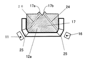
なお、本実施の形態では生体測定用光学素子12は、図1に示すようなものであるとして説明したが、これに限らず、図3に示すような生体測定用光学素子12aを用いることも出来る。生体測定用光学素子12aには、光出射面17a及び光入射面17bとを有する溝部17が設けられており、光源11から出射された光を光出射面17aに導く光ファイバ26が設けられている。また、光入射面17bから入射した光を光検出器16に導く光ファイバ24が設けられている。生体測定用光学素子12aは、生体測定用光学素子12aの溝部17の部分を生体表面に押し当て、生体表面のうち溝部17に入り込んだ部分を透過する光を検出することによって生体情報の測定を行うのに用いられる。このような構成の生体測定用光学素子12aを生体測定用光学素子12の代わりに用いても本実施の形態と同様の効果を得ることが出来る。
The
本発明に係る生体情報測定装置及び標準素子は、光源、生体測定用光学素子、及び光検出器の感度チェックを行うことができ、温度変化、経年変化による測定誤差を補正することができという効果を有し、生体組織を光学的に測定することによって体液中のグルコース、コレステロール、尿素、トリグリセリド等を非侵襲的に測定するために使用する生体情報測定装置及び標準素子等に有用である。すなわち、本発明は、医療用途での体液成分の測定に有用である。 The biological information measuring device and a standard element of the present invention, a light source, a biometric optical element, and can be performed a sensitivity check of the photodetector, temperature change, that it is possible to correct the measurement errors due to aging has an effect, is useful in the biological information measuring device and a standard element child like used to measure glucose in body fluids, cholesterol, urea, triglycerides, etc. noninvasively by measuring the biological tissue optically . That is, the present invention is useful for measuring body fluid components in medical applications.
11 光源
12 生体測定用光学素子
13 保持台
14 導光体
15 カバー部
16 光検出器
17 溝部
21 演算部
22 記憶手段
23 表示部
DESCRIPTION OF
Claims (13)
前記光源から出射した光を生体に照射し、前記生体から帰還した光を受光する生体測定用光学素子と、
前記生体測定用光学素子で受光した前記光を検出する光検出器と、
前記生体測定用光学素子に接触して配置された状態で、前記生体測定用光学素子から照射された光が前記生体測定用光学素子に帰還するように前記光を導くことが出来る導光体とを備え、
前記導光体は、空気より屈折率が高く前記生体測定用光学素子の屈折率よりも屈折率が低い材料で形成されている、生体情報測定装置。 A light source;
A living body measuring optical element for irradiating a living body with light emitted from the light source and receiving light returned from the living body;
A photodetector for detecting the light received by the biometric optical element;
Wherein in a state of being disposed in contact with the optical element biodata measurement, the biometric optical element wherein the optical light guide Ru can direct the body so that the irradiated light returns to the optical element for the biometric from It equipped with a door,
The biological information measuring device, wherein the light guide is formed of a material having a refractive index higher than air and a refractive index lower than that of the biological optical element .
前記導光体を前記生体測定用光学素子に接触するように配置させた状態で前記光検出器により検出された光に基づき、前記演算部が、前記光源、前記生体測定用光学素子及び前記光検出器の少なくともいずれかが異常であることを検出する、請求項1記載の生体情報測定装置。 Based on the light detected by the photodetector and returned from the living body, further comprising a calculation unit that calculates biological information of the living body,
Based on the light detected by the photodetector in a state where the light guide is placed in contact with the biometric optical element, the calculation unit includes the light source, the biometric optical element, and the light. The living body information measuring device according to claim 1 which detects that at least one of detectors is abnormal.
前記導光体を前記生体測定用光学素子に接触するように配置させた状態で前記光検出器により検出された光に基づき、前記演算部が前記生体情報を校正する、請求項1記載の生体情報測定装置。 Based on the light detected by the photodetector and returned from the living body, further comprising a calculation unit that calculates biological information of the living body,
The living body according to claim 1, wherein the calculation unit calibrates the biological information based on light detected by the photodetector in a state where the light guide is arranged so as to contact the optical element for biological measurement. Information measuring device.
前記導光体の前記生体測定用光学素子に接触する部分は変形可能である、請求項1記載の生体情報測定装置。 A part of the surface of the biometric optical element is formed with irregularities,
The biological information measuring apparatus according to claim 1, wherein a portion of the light guide that contacts the optical element for biological measurement is deformable.
前記光源から出射した光を生体に照射し、前記生体から帰還した光を受光する生体測定用光学素子と、
前記生体測定用光学素子で受光した前記光を検出する光検出器とを備えた生体情報測定装置のための標準素子であって、
前記生体測定用光学素子に接触して配置された状態で、前記生体測定用光学素子から照射された光が前記生体測定用光学素子に帰還するように前記光を導くことが出来る導光体を備え、
前記導光体は、空気より屈折率が高く前記生体測定用光学素子の屈折率よりも屈折率が低い材料で形成されている、標準素子。 A light source;
A living body measuring optical element for irradiating a living body with light emitted from the light source and receiving light returned from the living body;
A standard element for a biological information measuring device comprising a photodetector for detecting the light received by the optical element for biological measurement,
A light guide capable of guiding the light so that light emitted from the biometric optical element returns to the biometric optical element in a state of being placed in contact with the biometric optical element; Prepared ,
The light guide is a standard element made of a material having a higher refractive index than air and a lower refractive index than the refractive index of the biometric optical element.
Priority Applications (5)
| Application Number | Priority Date | Filing Date | Title |
|---|---|---|---|
| JP2004172101A JP4170262B2 (en) | 2004-06-10 | 2004-06-10 | Biological information measuring device and standard element |
| PCT/JP2004/008520 WO2005120361A1 (en) | 2004-06-10 | 2004-06-10 | Living body information measuring instrument, standard element, and method of using living body information measuring instrument |
| CNA2004800007503A CN1771010A (en) | 2004-06-10 | 2004-06-10 | Biological information measuring apparatus, reference device, and usage of biological information measuring apparatus |
| EP04746035A EP1754443A4 (en) | 2004-06-10 | 2004-06-10 | Living body information measuring instrument, standard element, and method of using living body information measuring instrument |
| US10/527,353 US20060173353A1 (en) | 2004-06-10 | 2004-06-10 | Biological information measuring apparatus,reference element, and method of using the biological information measuring apparatus |
Applications Claiming Priority (1)
| Application Number | Priority Date | Filing Date | Title |
|---|---|---|---|
| JP2004172101A JP4170262B2 (en) | 2004-06-10 | 2004-06-10 | Biological information measuring device and standard element |
Publications (3)
| Publication Number | Publication Date |
|---|---|
| JP2005348912A JP2005348912A (en) | 2005-12-22 |
| JP2005348912A5 JP2005348912A5 (en) | 2007-06-28 |
| JP4170262B2 true JP4170262B2 (en) | 2008-10-22 |
Family
ID=35502783
Family Applications (1)
| Application Number | Title | Priority Date | Filing Date |
|---|---|---|---|
| JP2004172101A Expired - Fee Related JP4170262B2 (en) | 2004-06-10 | 2004-06-10 | Biological information measuring device and standard element |
Country Status (5)
| Country | Link |
|---|---|
| US (1) | US20060173353A1 (en) |
| EP (1) | EP1754443A4 (en) |
| JP (1) | JP4170262B2 (en) |
| CN (1) | CN1771010A (en) |
| WO (1) | WO2005120361A1 (en) |
Families Citing this family (14)
| Publication number | Priority date | Publication date | Assignee | Title |
|---|---|---|---|---|
| JP5060268B2 (en) * | 2007-12-18 | 2012-10-31 | 浜松ホトニクス株式会社 | Biological measuring device and calibration jig |
| WO2015019392A1 (en) * | 2013-08-05 | 2015-02-12 | パイオニア株式会社 | Information detector and information measurement device, and information detection method |
| WO2016056477A1 (en) * | 2014-10-10 | 2016-04-14 | オリンパス株式会社 | Light source device |
| JP6415606B2 (en) | 2015-01-21 | 2018-10-31 | 国立研究開発法人量子科学技術研究開発機構 | Blood substance concentration measuring device and blood substance concentration measuring method |
| JP2016150130A (en) * | 2015-02-18 | 2016-08-22 | セイコーエプソン株式会社 | Information acquisition device and information acquisition method |
| JP2016154648A (en) * | 2015-02-24 | 2016-09-01 | セイコーエプソン株式会社 | Information acquisition device |
| WO2016187847A1 (en) * | 2015-05-27 | 2016-12-01 | 深圳市长桑技术有限公司 | Signal acquisition method and system |
| EP3111842A1 (en) * | 2015-06-30 | 2017-01-04 | Nokia Technologies Oy | An apparatus comprising a light detector, a light source and optics |
| JP2017213040A (en) * | 2016-05-30 | 2017-12-07 | セイコーエプソン株式会社 | Biological information acquisition device and biological information acquisition method |
| JP2018102849A (en) * | 2016-12-28 | 2018-07-05 | オムロンヘルスケア株式会社 | Biological sound measurement device |
| CN107969905B (en) * | 2017-12-22 | 2020-05-05 | 浙江浩鑫家庭用品有限公司 | Intelligent stewpan |
| CN107981706B (en) * | 2017-12-22 | 2020-06-26 | 福州盛世凌云环保科技有限公司 | Stewpan |
| CN108041972B (en) * | 2017-12-22 | 2020-06-26 | 福州盛世凌云环保科技有限公司 | Stewpan helpful for blood fat health care |
| CN108185796B (en) * | 2017-12-22 | 2020-06-30 | 福州盛世凌云环保科技有限公司 | Intelligent stewpan based on biological detection |
Family Cites Families (16)
| Publication number | Priority date | Publication date | Assignee | Title |
|---|---|---|---|---|
| GB8813307D0 (en) * | 1988-06-06 | 1988-07-13 | Amersham Int Plc | Biological sensors |
| JPH0614922B2 (en) * | 1991-02-15 | 1994-03-02 | 日本光電工業株式会社 | Calibration test equipment for pulse oximeter |
| IL107602A0 (en) * | 1992-12-21 | 1994-02-27 | Johnson & Johnson Vision Prod | Method of inspecting ophthalmic lenses |
| US5919712A (en) * | 1993-05-18 | 1999-07-06 | University Of Utah Research Foundation | Apparatus and methods for multi-analyte homogeneous fluoro-immunoassays |
| US5677196A (en) * | 1993-05-18 | 1997-10-14 | University Of Utah Research Foundation | Apparatus and methods for multi-analyte homogeneous fluoro-immunoassays |
| US5512492A (en) * | 1993-05-18 | 1996-04-30 | University Of Utah Research Foundation | Waveguide immunosensor with coating chemistry providing enhanced sensitivity |
| US6226541B1 (en) * | 1996-01-17 | 2001-05-01 | Spectrx, Inc. | Apparatus and method for calibrating measurement systems |
| US6002482A (en) * | 1996-01-17 | 1999-12-14 | Spectrx, Inc. | Disposable calibration device |
| JP3770707B2 (en) * | 1997-08-26 | 2006-04-26 | 松下電器産業株式会社 | Attenuated total reflection measuring apparatus and method for measuring specific components using the same |
| JPH11155844A (en) * | 1997-11-27 | 1999-06-15 | Horiba Ltd | Living body measuring device with constant living body contact area |
| US6241663B1 (en) * | 1998-05-18 | 2001-06-05 | Abbott Laboratories | Method for improving non-invasive determination of the concentration of analytes in a biological sample |
| AU5140900A (en) * | 1999-05-18 | 2000-12-05 | Scimed Life Systems, Inc. | Optical biopsy system |
| US6667803B1 (en) * | 1999-06-03 | 2003-12-23 | Hutchinson Technology, Inc. | Calibration mode recognition and calibration algorithm for spectrophotometric instrument |
| EP1254631B1 (en) * | 2000-02-07 | 2010-10-13 | Panasonic Corporation | Biological information measuring instrument comprising a biological information collecting probe |
| JP3905764B2 (en) * | 2002-01-24 | 2007-04-18 | 株式会社東芝 | Small inspection equipment and quality control chip |
| US7110112B2 (en) * | 2002-03-06 | 2006-09-19 | Matsushita Electric Industrial Co., Ltd. | Concentration measuring instrument, concentration measuring contact apparatus, concentration measuring calculating apparatus, and concentration measuring method |
-
2004
- 2004-06-10 EP EP04746035A patent/EP1754443A4/en not_active Withdrawn
- 2004-06-10 WO PCT/JP2004/008520 patent/WO2005120361A1/en not_active Application Discontinuation
- 2004-06-10 JP JP2004172101A patent/JP4170262B2/en not_active Expired - Fee Related
- 2004-06-10 CN CNA2004800007503A patent/CN1771010A/en active Pending
- 2004-06-10 US US10/527,353 patent/US20060173353A1/en not_active Abandoned
Also Published As
| Publication number | Publication date |
|---|---|
| US20060173353A1 (en) | 2006-08-03 |
| EP1754443A1 (en) | 2007-02-21 |
| CN1771010A (en) | 2006-05-10 |
| WO2005120361A1 (en) | 2005-12-22 |
| EP1754443A4 (en) | 2008-10-22 |
| JP2005348912A (en) | 2005-12-22 |
Similar Documents
| Publication | Publication Date | Title |
|---|---|---|
| JP4170262B2 (en) | Biological information measuring device and standard element | |
| US10631763B2 (en) | Method for glucose monitoring | |
| JP4701468B2 (en) | Biological information measuring device | |
| US6045502A (en) | Analyzing system with disposable calibration device | |
| JP4494779B2 (en) | Non-invasive glucose meter | |
| US7236814B2 (en) | Optical member for biological information measurement, biological information calculation apparatus, biological information calculation method, computer-executable program, and recording medium | |
| JP4792540B1 (en) | Pulse oximeter | |
| US20080218696A1 (en) | Non-Invasive Monitoring System | |
| US6882873B2 (en) | Method and system for determining bilirubin concentration | |
| JP2004089546A (en) | Blood analyzer | |
| US20220386875A1 (en) | Measuring apparatus and biological information measuring apparatus | |
| JP4466562B2 (en) | Optical fat measuring device | |
| JP4216272B2 (en) | Biological information measuring optical member and biological information calculating apparatus | |
| JPH08503767A (en) | Device for qualitative and / or quantitative analysis of samples | |
| JP2004527753A (en) | Portable automatic refractometer | |
| US20040242978A1 (en) | Apparatus for measuring biological information and method for measuring biological information | |
| JP2008154873A (en) | Optical measuring instrument | |
| KR100781968B1 (en) | Variable light-path gas density sensor | |
| EP3502666B1 (en) | Device for measuring backscattered radiation by a sample and measuring method using such a device | |
| JP2008154687A (en) | Optical measurement unit and optical measurement method using it | |
| TWI503546B (en) | Apparatus and method for estimating bilirubin concentration using refractometry | |
| JP2007178325A (en) | Chip for inspecting optical measuring instrument, inspection method of the optical measuring instrument, manufacturing method of the optical measuring instrument and usage method of the optical measuring instrument | |
| JP2019007824A (en) | Optical acoustic measurement probe | |
| JPWO2005115244A1 (en) | Biological information measuring optical element and biological information measuring apparatus using the same | |
| EP3919891A1 (en) | Device and method for measuring blood sugar level |
Legal Events
| Date | Code | Title | Description |
|---|---|---|---|
| A521 | Written amendment |
Free format text: JAPANESE INTERMEDIATE CODE: A523 Effective date: 20070515 |
|
| A621 | Written request for application examination |
Free format text: JAPANESE INTERMEDIATE CODE: A621 Effective date: 20070515 |
|
| A871 | Explanation of circumstances concerning accelerated examination |
Free format text: JAPANESE INTERMEDIATE CODE: A871 Effective date: 20080618 |
|
| TRDD | Decision of grant or rejection written | ||
| A975 | Report on accelerated examination |
Free format text: JAPANESE INTERMEDIATE CODE: A971005 Effective date: 20080704 |
|
| A01 | Written decision to grant a patent or to grant a registration (utility model) |
Free format text: JAPANESE INTERMEDIATE CODE: A01 Effective date: 20080715 |
|
| A01 | Written decision to grant a patent or to grant a registration (utility model) |
Free format text: JAPANESE INTERMEDIATE CODE: A01 |
|
| A61 | First payment of annual fees (during grant procedure) |
Free format text: JAPANESE INTERMEDIATE CODE: A61 Effective date: 20080806 |
|
| FPAY | Renewal fee payment (event date is renewal date of database) |
Free format text: PAYMENT UNTIL: 20110815 Year of fee payment: 3 |
|
| R150 | Certificate of patent or registration of utility model |
Free format text: JAPANESE INTERMEDIATE CODE: R150 |
|
| LAPS | Cancellation because of no payment of annual fees |