JP4216272B2 - Biological information measuring optical member and biological information calculating apparatus - Google Patents
Biological information measuring optical member and biological information calculating apparatus Download PDFInfo
- Publication number
- JP4216272B2 JP4216272B2 JP2005216435A JP2005216435A JP4216272B2 JP 4216272 B2 JP4216272 B2 JP 4216272B2 JP 2005216435 A JP2005216435 A JP 2005216435A JP 2005216435 A JP2005216435 A JP 2005216435A JP 4216272 B2 JP4216272 B2 JP 4216272B2
- Authority
- JP
- Japan
- Prior art keywords
- biological information
- light
- living tissue
- optical member
- cover
- Prior art date
- Legal status (The legal status is an assumption and is not a legal conclusion. Google has not performed a legal analysis and makes no representation as to the accuracy of the status listed.)
- Expired - Fee Related
Links
- 230000003287 optical effect Effects 0.000 title claims description 97
- 238000004364 calculation method Methods 0.000 claims description 22
- 238000001514 detection method Methods 0.000 claims description 10
- 230000006837 decompression Effects 0.000 claims description 5
- 239000006096 absorbing agent Substances 0.000 claims description 4
- 239000000126 substance Substances 0.000 claims description 3
- 210000001519 tissue Anatomy 0.000 description 171
- 238000005259 measurement Methods 0.000 description 77
- 238000003860 storage Methods 0.000 description 33
- 235000004522 Pentaglottis sempervirens Nutrition 0.000 description 23
- 240000004050 Pentaglottis sempervirens Species 0.000 description 19
- 239000013307 optical fiber Substances 0.000 description 14
- 239000000463 material Substances 0.000 description 12
- WQZGKKKJIJFFOK-GASJEMHNSA-N Glucose Natural products OC[C@H]1OC(O)[C@H](O)[C@@H](O)[C@@H]1O WQZGKKKJIJFFOK-GASJEMHNSA-N 0.000 description 8
- 239000008103 glucose Substances 0.000 description 8
- XUIMIQQOPSSXEZ-UHFFFAOYSA-N Silicon Chemical compound [Si] XUIMIQQOPSSXEZ-UHFFFAOYSA-N 0.000 description 6
- HVYWMOMLDIMFJA-DPAQBDIFSA-N cholesterol Chemical compound C1C=C2C[C@@H](O)CC[C@]2(C)[C@@H]2[C@@H]1[C@@H]1CC[C@H]([C@H](C)CCCC(C)C)[C@@]1(C)CC2 HVYWMOMLDIMFJA-DPAQBDIFSA-N 0.000 description 6
- 229910052710 silicon Inorganic materials 0.000 description 6
- 239000010703 silicon Substances 0.000 description 6
- 230000002411 adverse Effects 0.000 description 5
- 238000010586 diagram Methods 0.000 description 5
- 230000002093 peripheral effect Effects 0.000 description 5
- 239000010409 thin film Substances 0.000 description 5
- 238000010521 absorption reaction Methods 0.000 description 4
- 239000008280 blood Substances 0.000 description 4
- 210000004369 blood Anatomy 0.000 description 4
- 210000001124 body fluid Anatomy 0.000 description 4
- 239000010839 body fluid Substances 0.000 description 4
- 238000007796 conventional method Methods 0.000 description 4
- 230000000694 effects Effects 0.000 description 4
- 229910052732 germanium Inorganic materials 0.000 description 4
- GNPVGFCGXDBREM-UHFFFAOYSA-N germanium atom Chemical compound [Ge] GNPVGFCGXDBREM-UHFFFAOYSA-N 0.000 description 4
- XSQUKJJJFZCRTK-UHFFFAOYSA-N Urea Chemical compound NC(N)=O XSQUKJJJFZCRTK-UHFFFAOYSA-N 0.000 description 3
- 230000005540 biological transmission Effects 0.000 description 3
- 235000012000 cholesterol Nutrition 0.000 description 3
- 239000013078 crystal Substances 0.000 description 3
- 239000000428 dust Substances 0.000 description 3
- 239000010408 film Substances 0.000 description 3
- 238000000034 method Methods 0.000 description 3
- SBIBMFFZSBJNJF-UHFFFAOYSA-N selenium;zinc Chemical compound [Se]=[Zn] SBIBMFFZSBJNJF-UHFFFAOYSA-N 0.000 description 3
- ZOXJGFHDIHLPTG-UHFFFAOYSA-N Boron Chemical compound [B] ZOXJGFHDIHLPTG-UHFFFAOYSA-N 0.000 description 2
- LFQSCWFLJHTTHZ-UHFFFAOYSA-N Ethanol Chemical compound CCO LFQSCWFLJHTTHZ-UHFFFAOYSA-N 0.000 description 2
- OAICVXFJPJFONN-UHFFFAOYSA-N Phosphorus Chemical compound [P] OAICVXFJPJFONN-UHFFFAOYSA-N 0.000 description 2
- VYPSYNLAJGMNEJ-UHFFFAOYSA-N Silicium dioxide Chemical compound O=[Si]=O VYPSYNLAJGMNEJ-UHFFFAOYSA-N 0.000 description 2
- 230000002238 attenuated effect Effects 0.000 description 2
- 238000005102 attenuated total reflection Methods 0.000 description 2
- WQZGKKKJIJFFOK-VFUOTHLCSA-N beta-D-glucose Chemical compound OC[C@H]1O[C@@H](O)[C@H](O)[C@@H](O)[C@@H]1O WQZGKKKJIJFFOK-VFUOTHLCSA-N 0.000 description 2
- 229910052796 boron Inorganic materials 0.000 description 2
- WUKWITHWXAAZEY-UHFFFAOYSA-L calcium difluoride Chemical compound [F-].[F-].[Ca+2] WUKWITHWXAAZEY-UHFFFAOYSA-L 0.000 description 2
- 229910001634 calcium fluoride Inorganic materials 0.000 description 2
- 239000004202 carbamide Substances 0.000 description 2
- 230000007423 decrease Effects 0.000 description 2
- 238000013461 design Methods 0.000 description 2
- 229920001971 elastomer Polymers 0.000 description 2
- 239000005350 fused silica glass Substances 0.000 description 2
- 229910052736 halogen Inorganic materials 0.000 description 2
- 150000002367 halogens Chemical class 0.000 description 2
- 239000012535 impurity Substances 0.000 description 2
- 229910003465 moissanite Inorganic materials 0.000 description 2
- 229910052698 phosphorus Inorganic materials 0.000 description 2
- 239000011574 phosphorus Substances 0.000 description 2
- 239000004033 plastic Substances 0.000 description 2
- 108090000623 proteins and genes Proteins 0.000 description 2
- 102000004169 proteins and genes Human genes 0.000 description 2
- 230000005855 radiation Effects 0.000 description 2
- 229910010271 silicon carbide Inorganic materials 0.000 description 2
- 238000002834 transmittance Methods 0.000 description 2
- UFTFJSFQGQCHQW-UHFFFAOYSA-N triformin Chemical compound O=COCC(OC=O)COC=O UFTFJSFQGQCHQW-UHFFFAOYSA-N 0.000 description 2
- YBNMDCCMCLUHBL-UHFFFAOYSA-N (2,5-dioxopyrrolidin-1-yl) 4-pyren-1-ylbutanoate Chemical compound C=1C=C(C2=C34)C=CC3=CC=CC4=CC=C2C=1CCCC(=O)ON1C(=O)CCC1=O YBNMDCCMCLUHBL-UHFFFAOYSA-N 0.000 description 1
- PFNQVRZLDWYSCW-UHFFFAOYSA-N (fluoren-9-ylideneamino) n-naphthalen-1-ylcarbamate Chemical compound C12=CC=CC=C2C2=CC=CC=C2C1=NOC(=O)NC1=CC=CC2=CC=CC=C12 PFNQVRZLDWYSCW-UHFFFAOYSA-N 0.000 description 1
- 229910018072 Al 2 O 3 Inorganic materials 0.000 description 1
- 101100457849 Caenorhabditis elegans mon-2 gene Proteins 0.000 description 1
- 229910019912 CrN Inorganic materials 0.000 description 1
- 229910019974 CrSi Inorganic materials 0.000 description 1
- 229910005329 FeSi 2 Inorganic materials 0.000 description 1
- 229910000530 Gallium indium arsenide Inorganic materials 0.000 description 1
- 244000043261 Hevea brasiliensis Species 0.000 description 1
- 229910016006 MoSi Inorganic materials 0.000 description 1
- 229910005881 NiSi 2 Inorganic materials 0.000 description 1
- 229910004298 SiO 2 Inorganic materials 0.000 description 1
- 229910000577 Silicon-germanium Inorganic materials 0.000 description 1
- 229910010413 TiO 2 Inorganic materials 0.000 description 1
- 229910008484 TiSi Inorganic materials 0.000 description 1
- ATJFFYVFTNAWJD-UHFFFAOYSA-N Tin Chemical compound [Sn] ATJFFYVFTNAWJD-UHFFFAOYSA-N 0.000 description 1
- XAGFODPZIPBFFR-UHFFFAOYSA-N aluminium Chemical compound [Al] XAGFODPZIPBFFR-UHFFFAOYSA-N 0.000 description 1
- 229910052782 aluminium Inorganic materials 0.000 description 1
- 229910021417 amorphous silicon Inorganic materials 0.000 description 1
- 238000005422 blasting Methods 0.000 description 1
- 229910052793 cadmium Inorganic materials 0.000 description 1
- BDOSMKKIYDKNTQ-UHFFFAOYSA-N cadmium atom Chemical compound [Cd] BDOSMKKIYDKNTQ-UHFFFAOYSA-N 0.000 description 1
- 238000005229 chemical vapour deposition Methods 0.000 description 1
- 229910052804 chromium Inorganic materials 0.000 description 1
- 229910052802 copper Inorganic materials 0.000 description 1
- 238000011161 development Methods 0.000 description 1
- 229910003460 diamond Inorganic materials 0.000 description 1
- 239000010432 diamond Substances 0.000 description 1
- 230000005684 electric field Effects 0.000 description 1
- 239000000835 fiber Substances 0.000 description 1
- 238000005286 illumination Methods 0.000 description 1
- WPYVAWXEWQSOGY-UHFFFAOYSA-N indium antimonide Chemical compound [Sb]#[In] WPYVAWXEWQSOGY-UHFFFAOYSA-N 0.000 description 1
- 229910052742 iron Inorganic materials 0.000 description 1
- 238000000608 laser ablation Methods 0.000 description 1
- 238000004943 liquid phase epitaxy Methods 0.000 description 1
- 238000000691 measurement method Methods 0.000 description 1
- QSHDDOUJBYECFT-UHFFFAOYSA-N mercury Chemical compound [Hg] QSHDDOUJBYECFT-UHFFFAOYSA-N 0.000 description 1
- 229910052753 mercury Inorganic materials 0.000 description 1
- 229910052750 molybdenum Inorganic materials 0.000 description 1
- 210000004400 mucous membrane Anatomy 0.000 description 1
- 229920003052 natural elastomer Polymers 0.000 description 1
- 229920001194 natural rubber Polymers 0.000 description 1
- 229910052759 nickel Inorganic materials 0.000 description 1
- 230000003647 oxidation Effects 0.000 description 1
- 238000007254 oxidation reaction Methods 0.000 description 1
- 230000033116 oxidation-reduction process Effects 0.000 description 1
- 230000035515 penetration Effects 0.000 description 1
- 238000003825 pressing Methods 0.000 description 1
- 230000002265 prevention Effects 0.000 description 1
- 238000004445 quantitative analysis Methods 0.000 description 1
- 238000007788 roughening Methods 0.000 description 1
- 239000004065 semiconductor Substances 0.000 description 1
- HBMJWWWQQXIZIP-UHFFFAOYSA-N silicon carbide Chemical compound [Si+]#[C-] HBMJWWWQQXIZIP-UHFFFAOYSA-N 0.000 description 1
- 229920002379 silicone rubber Polymers 0.000 description 1
- 239000002356 single layer Substances 0.000 description 1
- 238000005245 sintering Methods 0.000 description 1
- 238000001228 spectrum Methods 0.000 description 1
- 229910052714 tellurium Inorganic materials 0.000 description 1
- PORWMNRCUJJQNO-UHFFFAOYSA-N tellurium atom Chemical compound [Te] PORWMNRCUJJQNO-UHFFFAOYSA-N 0.000 description 1
- 238000012360 testing method Methods 0.000 description 1
- WFKWXMTUELFFGS-UHFFFAOYSA-N tungsten Chemical compound [W] WFKWXMTUELFFGS-UHFFFAOYSA-N 0.000 description 1
- 229910052721 tungsten Inorganic materials 0.000 description 1
- 239000010937 tungsten Substances 0.000 description 1
- 238000001771 vacuum deposition Methods 0.000 description 1
- 238000007740 vapor deposition Methods 0.000 description 1
Images


Classifications
-
- A—HUMAN NECESSITIES
- A61—MEDICAL OR VETERINARY SCIENCE; HYGIENE
- A61B—DIAGNOSIS; SURGERY; IDENTIFICATION
- A61B5/00—Measuring for diagnostic purposes; Identification of persons
- A61B5/145—Measuring characteristics of blood in vivo, e.g. gas concentration, pH value; Measuring characteristics of body fluids or tissues, e.g. interstitial fluid, cerebral tissue
- A61B5/14532—Measuring characteristics of blood in vivo, e.g. gas concentration, pH value; Measuring characteristics of body fluids or tissues, e.g. interstitial fluid, cerebral tissue for measuring glucose, e.g. by tissue impedance measurement
-
- A—HUMAN NECESSITIES
- A61—MEDICAL OR VETERINARY SCIENCE; HYGIENE
- A61B—DIAGNOSIS; SURGERY; IDENTIFICATION
- A61B5/00—Measuring for diagnostic purposes; Identification of persons
- A61B5/68—Arrangements of detecting, measuring or recording means, e.g. sensors, in relation to patient
- A61B5/6801—Arrangements of detecting, measuring or recording means, e.g. sensors, in relation to patient specially adapted to be attached to or worn on the body surface
- A61B5/6813—Specially adapted to be attached to a specific body part
- A61B5/6814—Head
- A61B5/682—Mouth, e.g., oral cavity; tongue; Lips; Teeth
-
- G—PHYSICS
- G01—MEASURING; TESTING
- G01N—INVESTIGATING OR ANALYSING MATERIALS BY DETERMINING THEIR CHEMICAL OR PHYSICAL PROPERTIES
- G01N21/00—Investigating or analysing materials by the use of optical means, i.e. using sub-millimetre waves, infrared, visible or ultraviolet light
- G01N21/17—Systems in which incident light is modified in accordance with the properties of the material investigated
- G01N21/55—Specular reflectivity
- G01N21/552—Attenuated total reflection
-
- G—PHYSICS
- G01—MEASURING; TESTING
- G01N—INVESTIGATING OR ANALYSING MATERIALS BY DETERMINING THEIR CHEMICAL OR PHYSICAL PROPERTIES
- G01N21/00—Investigating or analysing materials by the use of optical means, i.e. using sub-millimetre waves, infrared, visible or ultraviolet light
- G01N21/17—Systems in which incident light is modified in accordance with the properties of the material investigated
- G01N21/25—Colour; Spectral properties, i.e. comparison of effect of material on the light at two or more different wavelengths or wavelength bands
- G01N21/31—Investigating relative effect of material at wavelengths characteristic of specific elements or molecules, e.g. atomic absorption spectrometry
- G01N21/35—Investigating relative effect of material at wavelengths characteristic of specific elements or molecules, e.g. atomic absorption spectrometry using infrared light
Description
本発明は、生体組織を光学的に測定することによって、体液中のグルコース、コレステロール、尿素、トリグリセリド、タンパク質等を非侵襲的に算出するための、生体情報測定用光学部材、および生体情報算出装置に関する。 The present invention relates to an optical member for biological information measurement and a biological information calculation device for noninvasively calculating glucose, cholesterol, urea, triglyceride, protein and the like in a body fluid by optically measuring biological tissue. about the.
生体や溶液中の特定成分を測定するための従来の光学測定装置について説明する。 A conventional optical measurement apparatus for measuring a specific component in a living body or a solution will be described.
平行に向かい合った一対の反射面を備える透明な減衰全反射素子(以下、ATRプリズムと称する)に上下の口唇を密着させて、血糖値を測定するための光学測定装置がある
(たとえば、特許文献1参照)。この従来の光学測定装置を第1の従来技術と呼ぶ。
There is an optical measurement device for measuring blood glucose level by bringing the upper and lower lips into close contact with a transparent attenuated total reflection element (hereinafter referred to as an ATR prism) having a pair of reflecting surfaces facing in parallel (for example, Patent Documents). 1). This conventional optical measuring apparatus is referred to as a first prior art.
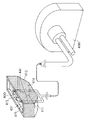
より具体的に述べると、従来の生体情報測定用光学部材の鳥瞰図である図12に示されているように、セレン化亜鉛、シリコンまたはゲルマニウム等からなるATRプリズム1201を口にくわえて、口唇1203によりATRプリズム1201を押さえつけた状態で、ATRプリズム1201に光ファイバ1202より光を入射させる。
More specifically, as shown in FIG. 12 which is a bird's eye view of a conventional optical member for measuring biological information, an
そして、ATRプリズム1201の反射面と口唇1203との境界でわずかに口唇1203に浸入しつつ全反射する(すなわち、減衰全反射する)ことを繰り返し、ATRプリズム1201の外部に出射した光を、光ファイバ1204を利用して取り出し、分析する。つまり、出射した光の光スペクトルを解析し、測定対象である特定成分が吸収しやすい波長の光の光量を算出することによって、その波長の光が特定成分によってどれくらい吸収されたのかを知ることができる。かくして、生体中の特定成分を定量的に測定することができるわけである。
Then, it repeatedly repeats total reflection (that is, attenuated total reflection) while slightly entering the
また、ZnSe結晶等からなるATRプリズムを口唇の粘膜に密着させた後、このATRプリズムに波長9〜11μmのレーザ光を入射させ、ATRプリズムの内部で多重反射させ、その減衰全反射光、散乱反射光等を分析することによって、血糖値や血中エタノール濃度を測定するための光学測定装置がある(たとえば、非特許文献1参照)。この従来の光学測定装置を第2の従来技術と呼ぶ。 Further, after an ATR prism made of ZnSe crystal or the like is brought into close contact with the mucous membrane of the lip, a laser beam having a wavelength of 9 to 11 μm is incident on the ATR prism, and multiple reflections are made inside the ATR prism, and the attenuated total reflected light and scattered light. There is an optical measurement device for measuring a blood glucose level and a blood ethanol concentration by analyzing reflected light or the like (see, for example, Non-Patent Document 1). This conventional optical measuring device is referred to as a second prior art.
ATRプリズム中を進行する光は、わずかに口唇に浸入した後に反射する。 The light traveling through the ATR prism reflects slightly after entering the lips.
反射した光は、口唇中に存在する体液中の各成分の影響をうけ、口唇に侵入する前よりも減衰している。 The reflected light is affected by each component in the body fluid present in the lips, and is attenuated more than before entering the lips.
そこで、反射光の光量を測定することにより、体液中の各成分の情報を得ることができる。 Therefore, by measuring the amount of reflected light, information on each component in the body fluid can be obtained.
第1および第2の従来技術は、エバネッセント波(いわゆる染み出し光)を定量分析に応用したものである。 The first and second conventional techniques apply evanescent waves (so-called oozing light) to quantitative analysis.
また、生体組織に当接される凹部を有する当接手段と、凹部内の一部より検出光を出射する検出光出射手段と、凹部内の他の一部に設けられ、検出光が入射される検出光入射手段を備え、当接手段は、生体組織の屈折率よりも高い屈折率を有する材料から構成され、当接手段と生体組織とが当接した状態で、検出光は凹部にはまり込んだ生体組織を通過した後に検出光入射手段に入射する生体情報検出用接触子がある(たとえば、特許文献2参照)。この従来の生体情報検出用接触子を第3の従来技術と呼ぶ。 In addition, a contact means having a recess that comes into contact with the living tissue, a detection light emitting means for emitting detection light from a part of the recess, and another part of the recess, the detection light is incident. And the contact means is made of a material having a refractive index higher than the refractive index of the biological tissue, and the detection light fits in the recess when the contact means and the biological tissue are in contact with each other. There is a contact for detecting living body information that enters a detection light incident means after passing through a living body tissue (see, for example, Patent Document 2). This conventional contact for detecting biological information is referred to as a third prior art.
生体組織へのダメージが少なく、容易かつ高精度に生体情報の測定が可能となる。
しかしながら、第1から第3の従来技術の何れにおいても、太陽光、照明からの光等の、測定用光源以外からの光は、外乱光となってしまうことが多い。 However, in any of the first to third conventional techniques, light from other than the measurement light source, such as sunlight and light from illumination, often becomes disturbance light.
このため、上述した従来の技術には、外乱光による生体情報測定への悪影響が発生することがあるという課題があった。 For this reason, the above-described conventional technique has a problem that adverse effects on measurement of biological information due to ambient light may occur.
なお、第1および第2の従来技術では、エバネッセント波の生体へ浸入する染み出し深さdは、およそ In the first and second prior arts, the penetration depth d that penetrates the living body of the evanescent wave is approximately

で求められる。 Is required.
ATRプリズムとしてZnSe結晶(n1=2.0)を用い、λ0=10ミクロン、θ1=45°とした場合について計算すると、生体の屈折率は約1.3〜1.5程度であるから、n2=1.41のときd=29ミクロンとなり、数十ミクロン程度の表面とその近傍の状態に関する情報が得られることが分かる。 When a ZnSe crystal (n 1 = 2.0) is used as an ATR prism and λ 0 = 10 microns and θ 1 = 45 ° is calculated, the refractive index of the living body is about 1.3 to 1.5. From this, it can be seen that when n 2 = 1.41, d = 29 microns, and information on the surface of about several tens of microns and the state in the vicinity thereof can be obtained.
ここに、エバネッセント波の電場は深さに応じて指数関数的に減衰していく。 Here, the electric field of the evanescent wave attenuates exponentially according to the depth.
したがって、生体組織をATRプリズムの生体組織測定部に密着させることが非常に重要である。 Therefore, it is very important that the living tissue is brought into close contact with the living tissue measurement unit of the ATR prism.
ところが、第1および第2の従来技術は、ともに、ATRプリズムを口唇にくわえたのみまたは押圧したのみである。 However, in both the first and second prior arts, the ATR prism is only added or pressed to the lips.
そのため、口唇とATRプリズムとを密着させることが困難である。 For this reason, it is difficult to bring the lips into close contact with the ATR prism.
このために、第1および第2の従来技術では、正確な生体情報の測定が困難になることがあった。 For this reason, in the first and second prior arts, accurate measurement of biological information may be difficult.
また、第3の従来技術では、形成された凹部に生体組織を隆起させ、隆起させた部位を選択的に測定することが可能になるが、やはり前述の第1、第2の従来技術と同様に生体組織と生体組織測定部との密着が非常に重要である。 Further, in the third prior art, it is possible to raise the living tissue in the formed concave portion and selectively measure the raised portion, which is also the same as the first and second conventional techniques described above. In addition, the close contact between the living tissue and the living tissue measurement unit is very important.
しかしながら、生体組織と生体組織測定部の密着が困難であるために、生体組織と生体組織測定部の密着が不十分である場合には光路長が変化してしまい、正確な生体情報の測定が困難になることがあった。 However, since the close contact between the living tissue and the living tissue measuring unit is difficult, the optical path length changes when the close contact between the living tissue and the living tissue measuring unit is insufficient, and accurate biological information measurement is possible. It could be difficult.
本発明は、上記従来のこのような課題を考慮し、外乱光による生体情報測定への悪影響を抑制することができる、生体情報測定用光学部材、および生体情報算出装置を提供することを目的とする。 An object of the present invention is to provide a biological information measuring optical member and a biological information calculating apparatus that can suppress adverse effects on biological information measurement due to ambient light in consideration of the above-described conventional problems. To do.
上記課題を解決する本発明は、
発光された光を入射する入射面、生体組織が接触する接触面、および前記生体組織が接触した前記接触面で反射された光、または前記生体組織が接触した前記接触面を介して前記生体組織を通過してきた光を出射する出射面を有する光学素子と、
前記接触面を露出させ、前記光学素子の外周部を包囲するように設けられた光学素子カバーとを備え、
前記生体組織の一部が入り込める空間が、前記光学素子と前記光学素子カバーとの間に形成されており、
前記接触面は、前記空間の外側に突出している、生体情報測定用光学部材である。
前記空間を覆うように設けられた、移動可能な空間カバーをさらに備え、
前記空間カバーは、前記接触面に接触した前記生体組織によって押圧されたときには、前記空間に沈み込むことが好ましい。
前記空間カバーは、弾性体によって保持されていることが好ましい。
前記生体組織が前記接触面に接触しているときに、前記空間を減圧する減圧手段をさらに備えたことが好ましい。
前記空間を覆うように設けられた、窓をもつ移動可能な空間カバーをさらに備え、
前記空間カバーは、前記接触面に接触した前記生体組織によって押圧されたときには、前記空間に沈み込み、
前記減圧手段は、前記窓を通じて排気を行うことによって、前記空間を減圧することが好ましい。
前記光学素子カバーの外面の全部または一部に設けられた減光手段をさらに備えていることが好ましい。
前記減光手段は、光を反射する光反射体、光を吸収する光吸収体、および光を散乱する光散乱体の内の少なくとも一つであることが好ましい。
前記接触面は、溝をもつことが好ましい。
前記光学素子は、屈折率が1.55以上であることが好ましい。
前記接触面は、曲面をもつことが好ましい。
前記光学素子カバーの端面の、前記生体組織に接触する部分は、曲面をもつことが好ましい。
本発明に係る生体情報測定用光学部材と、
前記光を発光する光源と、
前記出射面から出射された前記光を検出する光検出器と、
前記検出の結果に基づいて、前記生体組織を有する生体に関する生体情報を演算する演算部とを備えた、生体情報算出装置もまた、本発明の趣旨に含まれる。
演算される前記生体情報は、前記生体組織に含まれる物質の濃度に関する情報であることが好ましい。 The present invention for solving the above problems
The incident surface on which the emitted light is incident, the contact surface in contact with the living tissue, and the light reflected by the contact surface in contact with the living tissue, or the living tissue through the contact surface in contact with the living tissue An optical element having an exit surface that emits light that has passed through
An optical element cover provided so as to expose the contact surface and surround an outer periphery of the optical element;
A space into which a part of the living tissue can enter is formed between the optical element and the optical element cover ;
The contact surface is a biological information measuring optical member that protrudes outside the space .
A movable space cover provided to cover the space;
It is preferable that the space cover sinks into the space when pressed by the living tissue in contact with the contact surface.
The space cover is preferably held by an elastic body.
It is preferable that the apparatus further includes decompression means for decompressing the space when the living tissue is in contact with the contact surface.
A movable space cover having a window provided to cover the space;
When the space cover is pressed by the living tissue in contact with the contact surface, the space cover sinks into the space,
The decompression means preferably decompresses the space by exhausting through the window.
Preferably, the optical element cover further includes dimming means provided on all or part of the outer surface.
The dimming means is preferably at least one of a light reflector that reflects light, a light absorber that absorbs light, and a light scatterer that scatters light.
The contact surface preferably has a groove.
The optical element preferably has a refractive index of 1.55 or more.
The contact surface preferably has a curved surface.
The portion of the end face of the optical element cover that contacts the living tissue preferably has a curved surface.
An optical member for measuring biological information according to the present invention;
A light source that emits the light;
A photodetector for detecting the light emitted from the emission surface;
A biological information calculation apparatus including a calculation unit that calculates biological information related to a living body having the biological tissue based on the detection result is also included in the spirit of the present invention.
It is preferable that the biological information to be calculated is information regarding the concentration of a substance contained in the biological tissue.
本発明は、外乱光による生体情報測定への悪影響を抑制することができるという長所を有する。 The present invention has an advantage that adverse effects on biological information measurement due to ambient light can be suppressed.
以下、本発明の実施の形態について図面を参照しながら説明する。 Hereinafter, embodiments of the present invention will be described with reference to the drawings.
(実施の形態1)
はじめに、図1(a)〜(c)を主として参照しながら、本実施の形態の生体情報測定用光学部材の構成について説明する。
(Embodiment 1)
First, the configuration of the optical member for measuring biological information according to the present embodiment will be described with reference mainly to FIGS.
ここに、図1(a)は、本発明の実施の形態1の生体情報測定用光学部材の上面図であり、図1(b)は、本発明の実施の形態1の生体情報測定用光学部材の側面図であり、図1(c)は、本発明の実施の形態1の生体情報測定用光学部材の鳥瞰図である。
1A is a top view of the optical member for measuring biological information according to
図1(b)に示すように、本実施の形態の生体情報測定用光学部材は、光入射面11、光出射面12、生体組織測定部13、プリズムカバー14、生体組織格納部15から構成されている。
As shown in FIG. 1B, the biological information measuring optical member of the present embodiment includes a
つまり、本実施の形態の生体情報測定用光学部材は、発光された光を入射する光入射面11、口唇等の生体組織(図示せず)が接触する接触面に当たる生体組織測定部13、および生体組織が接触した生体組織測定部13で反射された光を出射する光出射面12を有するプリズム100と、生体組織測定部13を露出させ、プリズム100の外周部を包囲するように設けられたプリズムカバー14とを備えている。
That is, the optical member for measuring biological information according to the present embodiment includes a
プリズム100の材料は、測定に利用する光の波長に応じたものを用いることができる。
As the material of the
なお、プリズム100の材料の具体例としては、シリコン、ゲルマニウム、SiC、ダイアモンド、ZnSe、ZnS、溶融石英、フッ化カルシウム、プラスチックおよびKrS等が挙げられる。
Specific examples of the material of the
ここで、グルコースのように、波数1033cm−1、1080cm−1等の中赤外域と波長1〜2.5マイクロメートルの近赤外域に吸収ピークがあるような物質を測定する場合には、中赤外域では約1000〜1100cm−1の波数領域で透過率が高い材料が好ましい。
Here, as glucose, in the case wavenumber 1033cm -1, a material such as an absorption peak in the near infrared region in the infrared region and the
このような観点から、プリズム100の材料は、前述の透過率の低下の原因となるホウ素やリン等の不純物の含有量が小さい、シリコンやゲルマニウムであることが好ましい。なお、ホウ素やリン等の不純物の含有量が小さいほど、シリコンやゲルマニウムの抵抗率は高くなる。このため、その抵抗率が100Ωcm以上であれば好ましく、その抵抗率が1500Ωcm以上であればさらに好ましい。
From such a viewpoint, it is preferable that the material of the
近赤外域の場合には、プリズム100の材料は、シリコン、もしくは高屈折率プラスチックであって、シリコンの場合には、同様の理由により、抵抗率が100Ωcm以上のものが好ましく、抵抗率が1500Ωcm以上のものがさらに好ましい。なお、プリズム100の材料は、フッ化カルシウム、溶融石英等であっても良い。
In the near-infrared region, the material of the
図1(b)に示されているように、生体組織測定部13は、生体組織の一部が入り込む側のプリズムカバー14の端面よりも、生体組織格納部15の外側に突出している。
As shown in FIG. 1B, the biological
これは測定対象である生体組織を測定時に生体組織測定部13に接触させるが、生体組織測定部13をプリズムカバー14より突出させることにより、生体組織と生体組織測定部13の接触圧力を向上させることで、密着性を向上させるためである。
In this method, the living tissue to be measured is brought into contact with the living
図1(c)に示されているように、生体組織測定部13の外周部に生体組織測定部13を取り囲むように、プリズムカバー14が設けられている。
As shown in FIG. 1C, a
そして、このプリズムカバー14には、減光手段16が設けられている。
The
減光手段16は、光検出器に光の入射する確率を減らすためのものであればよく、光吸収体、光散乱体、光反射体の何れで構成してもよい。 The light reduction means 16 may be any means for reducing the probability of light entering the photodetector, and may be composed of a light absorber, light scatterer, or light reflector.
光吸収体の具体例としては、外乱光として考えられる各種波長の光を吸収する光学薄膜等が挙げられる。 Specific examples of the light absorber include an optical thin film that absorbs light of various wavelengths considered as disturbance light.
より具体的には、そのような光学薄膜を、膜内で光を多重干渉し効率よく不要な光を吸収できるように、適切な厚さの単層膜または多層膜で形成することが好ましい。 More specifically, it is preferable that such an optical thin film is formed of a single layer film or a multilayer film having an appropriate thickness so that multiple interference of light within the film and efficient absorption of unnecessary light can be achieved.
なお、このような光学薄膜の材料の具体例としては、Cu、Cr、Mo、Fe、Ni、アモルファスSi、SiC、Ge、WSi2、Ti、TiN、Ta、TiW、Co、SiGe、TiSi2、CrSi2、MoSi2、FeSi2、NiSi2、CrN、MoN2、SiO2、Al2O3およびTiO2等が挙げられる。
Specific examples of such an optical thin film material include Cu, Cr, Mo, Fe, Ni, amorphous Si, SiC, Ge, WSi 2 , Ti, TiN, Ta, TiW, Co, SiGe, TiSi 2 , CrSi 2, MoSi 2, FeSi 2 , NiSi 2, CrN, MoN 2, SiO 2, Al 2
また、このような光学薄膜の形成方法の具体例としては、化学気相成長法、プラズマ気相成長法、光CVD法、真空蒸着法、液相エピキタシー法、ゾル−ゲル法、陽極酸化反応法、酸化還元法、レーザアブレーション法等が挙げられる。 Specific examples of the method for forming such an optical thin film include chemical vapor deposition, plasma vapor deposition, photo CVD, vacuum deposition, liquid phase epitaxy, sol-gel, anodic oxidation. , Oxidation-reduction method, laser ablation method and the like.
光散乱体の具体例としては、光を散乱させるように、プリズムカバー14の表面をブラスト加工等で荒らしたもの等が挙げられる。
As a specific example of the light scatterer, a material obtained by roughening the surface of the
光反射体の具体例としては、アルミニウム等で形成された光学薄膜等が挙げられる。 Specific examples of the light reflector include an optical thin film formed of aluminum or the like.
また、図1(b)に示されているように、生体組織格納部15は、生体組織接触部13とプリズムカバー14の間に設けられ、凹部になっている。
Further, as shown in FIG. 1B, the living
なお、プリズム100は本発明の光学素子に対応し、プリズムカバー14は本発明の光学素子カバーに対応し、減光手段16は本発明の減光手段に対応する。
The
つぎに、本実施の形態の生体情報測定用光学部材の動作について説明する。 Next, the operation of the optical member for measuring biological information according to the present embodiment will be described.
まず、生体組織測定部13に生体組織を接触させる。
First, the living tissue is brought into contact with the living
その後、さらに押圧していくと、生体組織は、生体組織格納部15の凹部に入り込んでいく。
Thereafter, when the pressure is further pressed, the living tissue enters the concave portion of the living
このように生体組織を生体組織格納部15に入り込ませることで、生体組織と生体組織測定部13との密着性を向上させる。
In this way, the living tissue is allowed to enter the living
プリズムカバー14は、生体組織測定部13の外周部に設けることにより、生体組織格納部15を形成し、部屋の照明光、太陽光、人体からの輻射、その他測定に悪影響を及ぼす外乱光が生体組織測定部13に入射することを防ぐ。
The
なお、生体情報測定用光学部材を一体的に形成した場合の例を示したが、本発明の実施の形態の、生体組織測定部213とプリズムカバー214とが別体となった生体情報測定用光学部材の鳥瞰図である図2に示すように、プリズムカバー214に減光手段216を設けた部分を別途作成し、その後、光入射面211、生体組織測定部213等を有する部分を組み込んでもよい。なお、光入射面211、生体組織測定部213等を有する部分の外側面の内、組み込みが行われた後にも外部に露出する部分(光入射面211や光出射面を除く、なお、図2においては斜線が施されている)には、外乱光が生体組織測定部213に入射することを防ぐための減光手段が設けられていてもよい。
In addition, although the example at the time of integrally forming the optical member for biological information measurement was shown, the biological
(実施の形態2)
はじめに、図3(a)〜(c)を主として参照しながら、本実施の形態の生体情報測定用光学部材の構成について説明する。
(Embodiment 2)
First, the configuration of the optical member for measuring biological information according to the present embodiment will be described with reference mainly to FIGS.
ここに、図3(a)は、本発明の実施の形態2の、動作前における生体情報測定用光学部材の鳥瞰図であり、図3(b)は、本発明の実施の形態2の、動作後における、すなわち生体組織を生体組織測定部313に接触させた状態における生体情報測定用光学部材の鳥瞰図であり、図3(c)は、本発明の実施の形態2の、動作前における生体情報測定用光学部材のA−A′線における断面図である。
Here, FIG. 3A is a bird's-eye view of the biological information measuring optical member before the operation according to the second embodiment of the present invention, and FIG. 3B is an operation according to the second embodiment of the present invention. FIG. 3C is a bird's-eye view of the optical member for biological information measurement later, that is, in a state where the biological tissue is brought into contact with the biological
本実施の形態の生体情報測定用光学部材の構成は前述した実施の形態1の生体情報測定用光学部材の構成と類似しているが、生体組織格納部カバー331が備えられている。この生体組織格納部カバー331には、生体組織測定部313と実質的に等しい大きさ及び形状を有する切り欠き部334と、切り欠き部334の四隅からA−A′線に平行な方向に設けられた切り込み332(図3(a)においては点線で示されている)とが設けられている。
The configuration of the optical member for measuring biological information according to the present embodiment is similar to the configuration of the optical member for measuring biological information according to
切り欠き部334及び切り込み332が設けられているために、生体組織格納部カバー331は、図3(b)に示されているようにプリズム300に接触しながら沈み込むことができる。
Since the
このような観点から、生体組織格納部カバー331の材料は、シリコンゴムや天然ゴムなどの適度な弾性を有するゴムであることが好ましい。
From such a viewpoint, it is preferable that the material of the biological tissue
図3(c)に示されているように、バネ333が設けられているために、生体組織格納部カバー331は、生体組織を生体組織測定部313へ押圧した場合に沈み込み、生体組織を生体組織測定部313から外した場合に元の状態に復帰する。
As shown in FIG. 3C, since the
また、バネ333を設けることによって、生体組織格納部カバー331を沈みこませるために必要な力を、バネ333のバネ定数を適切に選んで設計することができるので、密着性向上のための最適設計ができる。
Further, by providing the
なお、生体組織格納部カバー331は、本発明の空間カバーに対応する。
The living tissue
つぎに、本実施の形態の生体情報測定用光学部材の動作について説明する。 Next, the operation of the optical member for measuring biological information according to the present embodiment will be described.
図3(a)に示すように、生体組織を生体組織測定部313に接触させる前段階では、生体組織格納部315は、生体組織格納部カバー331によって閉ざされている。
As shown in FIG. 3A, the biological
このため、生体情報測定用光学部材を保管する場合等にも、生体組織格納部315にチリ、ホコリ等のごみが入り込み難い。
For this reason, even when the optical member for measuring biological information is stored, dust such as dust and dust does not easily enter the biological
生体組織が生体組織測定部313に押圧された場合に、生体組織格納部カバー331が、生体組織を生体組織測定部313に押し当てる圧力により、図3(b)に示されているように沈み込む。
When the biological tissue is pressed by the biological
生体組織格納部カバー331には図3(a)に示されているような切り欠き部334及び切り込み332が設けられているので、図3(b)に示されているように生体組織格納部カバー331が沈み込むことができる。
Since the biological tissue
図3(c)に示されているように、バネ333が設けられているために、生体組織格納部カバー331は、生体組織を生体組織測定部313へ押圧すると沈み込み、生体組織を生体組織測定部313から外すと元の状態に復帰する。
As shown in FIG. 3C, since the
なお、バネ333の変わりにゴム等の弾性体を用いても良い。
Instead of the
また、生体組織格納部カバー331には、プリズムカバー314に設けられた減光手段316のような減光手段を必ずしも設ける必要はないが、生体組織からの輻射を防げるためにそのような減光手段を設けてもよい。
Further, the biological tissue
(実施の形態3)
はじめに、図4を主として参照しながら、本実施の形態の生体情報測定用光学部材の構成について説明する。
(Embodiment 3)
First, the configuration of the optical member for measuring biological information according to the present embodiment will be described with reference mainly to FIG.
ここに、図4は、本発明の実施の形態3の生体情報測定用光学部材の鳥瞰図である。
FIG. 4 is a bird's eye view of the biological information measuring optical member according to
本実施の形態の生体情報測定用光学部材の構成は前述した実施の形態2の生体情報測定用光学部材の構成と類似しているが、プリズム400、およびプリズムカバー414の底面部を貫通する吸引孔441が設けられている。
The configuration of the biological information measuring optical member of the present embodiment is similar to the configuration of the biological information measuring optical member of the second embodiment described above, but suction that penetrates the bottom surface of the
もちろん、生体組織格納部カバー431にも吸引孔441と重なる位置に丸い窓が設けられている。
Of course, the biological tissue
そのため、ポンプ499は、生体組織格納部カバー431がプリズム400に接触した生体組織によって押圧されて生体組織格納部415の内部に沈み込んだ際には、そのような窓を通じて排気を行うことによって、生体組織格納部415の内部を減圧することができるわけである。
Therefore, when the biological tissue
なお、ポンプ499は、本発明の減圧手段に対応する。
The
つぎに、本実施の形態の生体情報測定用光学部材の動作について説明する。 Next, the operation of the optical member for measuring biological information according to the present embodiment will be described.
生体組織を生体組織測定部413に接触させた後、ポンプ499を用いて吸引孔441より吸引を行って排気する。
After the living tissue is brought into contact with the living
そして、生体組織格納部415内を負圧にすることで、密着性を向上させる。
And the adhesiveness is improved by making the inside of the biological
なお、吸引を行うための孔は、プリズムカバー414の側面部を貫通するように設けられていてもよい。もちろん、このような場合には、吸引を行うための孔の位置によっては生体組織格納部カバー431に窓が設けられていなくてもよい。
Note that the hole for performing suction may be provided so as to penetrate the side surface of the
また、ポンプ499を用いる例を示したが、本発明の実施の形態の、吸引孔441に一方向バルブ911が設けられた生体情報測定用光学部材の鳥瞰図である図9に示すように、吸引孔441に逆流防止弁をもつ一方向バルブ911を設けてもよい。より具体的には、生体組織が生体組織測定部413に押圧された際に、生体組織が生体組織格納部415を満たすと、生体組織格納部415内の空気が吸引孔441から一方向バルブ911を通じて排気され、生体組織が生体組織測定部413に密着するような吸盤の構成を利用してもよい。
Moreover, although the example using the
以上においては、実施の形態1〜3について詳細に説明を行った。 In the above, Embodiment 1-3 was demonstrated in detail.
(A)なお、生体組織測定部が略平面状である場合について説明したが、本発明の実施の形態の、生体組織測定部513が溝551を有する生体情報測定用光学部材の鳥瞰図である図5(a)、および本発明の実施の形態の、溝551に生体組織599が密着し、密着した生体組織599の中を光552が透過しているときの模式図である図5(b)に示すように、生体組織測定部513が溝551を有するプリズム500を利用してもよい。
(A) In addition, although the case where the biological tissue measurement unit has a substantially planar shape has been described, the biological
図5(b)に示すように、生体組織測定部513に設けられた複数の溝551に生体組織599を密着させ、密着させた生体組織599に光552を透過させて測定を行う。
As shown in FIG. 5B, the
このようにすることによって、生体組織599が接触した生体組織測定部513を介して生体組織599を通過してきた光552の光路長が、複数の溝551の1つ分の寸法で決定される。このため、
In this way, the optical path length of the light 552 that has passed through the
に示されているランベルト−ベールの法則から分かるように、光路長が溝551の寸法によって機械的に決定され、精度よく測定を行うことができる。複数の溝551の内の一つの溝を形成する一方の面から出射した光552が、一方の面と生体組織599との界面で屈折し、その溝を形成する他方の面と生体組織599との界面まで生体組織599内を直進し、その界面で再び屈折して他方の面に帰還するように(図5(b)参照)、プリズム500の屈折率は生体の屈折率1.3〜1.5よりも高い1.55以上であることが好ましい。
As can be seen from the Lambert-Beer law, the optical path length is mechanically determined by the dimensions of the
もちろん、複数の溝551が設けられている場合について説明したが、本発明の実施の形態の、生体組織測定部1013が溝1051を有する生体情報測定用光学部材の鳥瞰図である図10(a)、本発明の実施の形態の、溝1051に生体組織1099が密着し、密着した生体組織1099の中を光1052が透過しているときの模式図である図10(b)に示すように、生体組織測定部1013が一つの溝1051を有するプリズム1000を利用してもよい。
Of course, the case where the plurality of
(B)また、本発明の実施の形態の、生体組織と接触する部分が丸くなった生体組織測定部613を備えた生体情報測定用光学部材の鳥瞰図である図6に示すように、生体組織測定部613の外周部を曲面にしてもよい。
(B) Moreover, as shown in FIG. 6 which is a bird's-eye view of the optical member for biological information measurement provided with the biological
このようにすることによって、生体組織をプリズム600の生体組織測定部613に押し付ける際、痛みを軽減できる。
By doing so, pain can be reduced when the biological tissue is pressed against the biological
なお、生体組織測定部613の外周部の曲面は、何れの方向に関しても丸みを帯びており、痛みを確実に軽減することができる。
In addition, the curved surface of the outer peripheral part of the biological
また、生体組織が生体組織格納部615により導入されやすくなり、生体組織測定部613の外周部が曲面でない場合と比較して、生体組織の変形がより緩やかになり、生体組織と生体組織測定部613の密着性を向上させることが可能である。
In addition, the living tissue is easily introduced by the living
もちろん、生体組織測定部613の外周部を曲面にするとともに、生体組織測定部613に溝551のような溝を設けてもよい。
Of course, the outer peripheral portion of the biological
(C)また、本発明の実施の形態の、生体組織と接触する部分が丸くなったプリズムカバー714を備えた生体情報測定用光学部材の鳥瞰図である図7に示すように、プリズムカバー714の端面の、生体組織に接触する部分を曲面にしてもよい。
(C) Moreover, as shown in FIG. 7 which is a bird's-eye view of the optical member for biological information measurement provided with the
このようにすると、生体組織を生体組織測定部713に押し当てる際、痛みを軽減でき、また、生体組織が生体組織格納部715により導入されやすくなるため好ましい。
This is preferable because pain can be reduced when the living tissue is pressed against the living
(D)また、プリズムを利用する場合について説明したが、本発明の実施の形態の、光ファイバの端部として生体組織測定部1113をもつ光ファイバ束1100、1101を有する生体情報測定用光学部材の鳥瞰図である図11(a)、および本発明の実施の形態の、隙間1151に生体組織1199が密着し、密着した生体組織1199の中を光1152が透過しているときの模式図である図11(b)に示すように、光ファイバ束1100、1101を利用してもよい。
(D) Moreover, although the case where a prism was utilized was demonstrated, the optical member for biological information measurement which has the
光1152は、光入射面1111から光ファイバ束1100に入射し、光ファイバ束1100を通過して、隙間1151側の光ファイバの端部から生体組織1199に入射する。そして、光1152は、生体組織1199から出射して、光ファイバ束1101の隙間1151側の光ファイバの端部から光ファイバ束1101に入射し、光ファイバ束1101を通過して、光出射面1112から出射する。
The light 1152 enters the
このようにすると、生体情報測定用光学部材の軽量化が実現できるため好ましい。 This is preferable because the biological information measuring optical member can be reduced in weight.
(実施の形態4)
はじめに、図8を主として参照しながら、本実施の形態の生体情報算出装置の構成について説明する。
(Embodiment 4)
First, the configuration of the biological information calculation apparatus of the present embodiment will be described with reference mainly to FIG.
ここに、図8は、本発明の実施の形態4の生体情報算出装置の概略図である。 FIG. 8 is a schematic diagram of the biological information calculation apparatus according to the fourth embodiment of the present invention.
本実施の形態の生体情報算出装置は、光を発光する光源881と、上述した実施の形態1で説明された生体情報測定用光学部材1と、プリズム100から出射された光を検出する光検出器882と、検出の結果に基づいて、生体組織を有する生体に関する生体情報を演算する演算部883とから構成されている。
The biological information calculation apparatus according to the present embodiment includes a
もちろん、光源881と生体情報測定用光学部材1との間には、グレーティングを用いた分光装置、フーリェ変換分光装置等の分光器(図示せず)が設けられていてもよい。
Of course, a spectroscope (not shown) such as a spectroscopic device using a grating or a Fourier transform spectroscopic device may be provided between the
光源881は、LD、LED、ハロゲン光源、半導体レーザ、SiCを棒状に焼結したグローバ光源、CO2レーザ、タングステン灯等のような、測定対象である測定成分の吸収波長の光を発する手段である。なお、光源881がLDである場合について図示を行っている。
The
光源881は、グルコースのように、波数1033cm−1、1080cm−1等の中赤外域と1〜2.5マイクロメートルの近赤外域に吸収ピークがあるような物質を測定する場合、中赤外光で測定する際には、比較的広い波長範囲をカバーすることができ、10マイクロメートル程度の長波長領域でも良好に発光するという観点から、グローバ光源が好ましい。また、光源881は、1000nmから2500nmの近赤外光を測定する場合は、ハロゲン光源が好ましい。
このように、発光される光は、波長が1000nmと10000nmとの間にある光を含んでいることが望ましい。 Thus, it is desirable that the emitted light includes light having a wavelength between 1000 nm and 10000 nm.
光検出器882は、中赤外域の場合は、水銀、テルル、カドミウムの混晶を利用するMCT検出器、焦電センサ、DTGS検出器、サーミスタ、サーモパイル、ゴーレイセル等、近赤外域の場合は、PbS検出器、InSb検出器、PbSe検出器、InGaAs検出器、Si検出器等の手段である。
In the case of the mid-infrared region, the
演算部883は、コンピュータである。
The
演算される生体情報の具体例としては、グルコース、トリグリセライド、尿素、コレステロール(総コレステロール)、およびタンパク質等の濃度に関する情報等が挙げられる。 Specific examples of the biological information to be calculated include information related to concentrations of glucose, triglyceride, urea, cholesterol (total cholesterol), and proteins.
なお、光源881は本発明の光源に対応し、光検出器882は本発明の光検出器に対応し、演算部883は本発明の演算部に対応する。
Note that the
つぎに、本実施の形態の生体情報算出装置の動作について説明する。 Next, the operation of the biological information calculation apparatus of this embodiment will be described.
なお、本実施の形態の生体情報算出装置の動作について説明しながら、本発明に関連する発明の生体情報算出方法の一実施の形態についても説明する。 While describing the operation of the biological information calculation apparatus of the present embodiment , an embodiment of the biological information calculation method of the invention related to the present invention will also be described.
光源881より発光された光852は、生体情報測定用光学部材1に入射する。
The light 852 emitted from the
生体情報測定用光学部材1に入射された光852は、生体組織測定部13に接触している生体組織で透過・散乱・吸収され、生体情報測定用光学部材1の光出射面12より出射される。
The light 852 incident on the biological information measuring
生体情報測定用光学部材1より出射された光852は、光検出器882によって検出される。
演算部883は、光検出器882による検出の結果を利用して、生体情報を演算する。
The
本実施の形態によれば、上述した実施の形態1で説明された生体情報測定用光学部材1が利用されるため、生体組織測定部以外の面から入射する迷光の影響を軽減し、生体組織と光学素子との密着性を向上させ、被検試料中の標的成分の濃度を安定かつ容易に演算することができ、たとえば医療用途での体液成分の測定に有用である。
According to the present embodiment, since the biological information measuring
なお、本発明に関連する発明のプログラムは、上述した本発明に関連する発明の生体情報算出方法の全部または一部のステップの動作をコンピュータにより実行させるためのプログラムであって、コンピュータと協働して動作するプログラムである。 The program of the invention relating to the present invention is a program for executing all or operation of some of the steps of the biological information calculation method of the invention related to the present invention described above by a computer, the computer in cooperation It is a program that operates as
また、本発明に関連する発明の記録媒体は、上述した本発明に関連する発明の生体情報算出方法の全部または一部のステップの全部または一部の動作をコンピュータにより実行させるためのプログラムを担持した記録媒体であり、コンピュータにより読み取り可能かつ、読み取られた前記プログラムが前記コンピュータと協動して前記動作を実行する記録媒体である。 The recording medium of the invention related to the present invention, carrying a program for executing all or a part of operations of all or part of the steps of the biological information calculation method of the invention related to the present invention described above by a computer The recording medium can be read by a computer, and the read program executes the operation in cooperation with the computer.
なお、上記「一部のステップ」とは、それらの複数のステップの内の、一つまたは幾つかのステップを意味する。 Incidentally, the upper SL as "some of the steps" is of those several steps, it means one or several steps.
また、上記「ステップの動作」とは、前記ステップの全部または一部の動作を意味する。 The upper SL and "step operation" means all or part of the operation of the step.
また、本発明に関連する発明のプログラムの一利用形態は、コンピュータにより読み取り可能な記録媒体に記録され、コンピュータと協働して動作する態様であっても良い。 Further, one use form of the program of the invention related to the present invention may be an aspect in which the program is recorded on a computer-readable recording medium and operates in cooperation with the computer.
また、本発明に関連する発明のプログラムの一利用形態は、伝送媒体中を伝送し、コンピュータにより読みとられ、コンピュータと協働して動作する態様であっても良い。 Further, one use form of the program of the invention related to the present invention may be an aspect in which the program is transmitted through a transmission medium, read by a computer, and operated in cooperation with the computer.
また、記録媒体としては、ROM等が含まれ、伝送媒体としては、インターネット等の伝送媒体、光・電波・音波等が含まれる。 Further, the recording medium includes a ROM and the like, and the transmission medium includes a transmission medium such as the Internet, light, radio waves, sound waves, and the like.
また、上述したコンピュータは、CPU等の純然たるハードウェアに限らず、ファームウェアや、OS、更に周辺機器を含むものであっても良い。 Moreover, computer described above is not limited to pure hardware such as a CPU, firmware or, OS, may be one further comprising a peripheral device.
なお、以上説明した様に、本発明または本発明に関連する発明の構成は、ソフトウェア的に実現しても良いし、ハードウェア的に実現しても良い。 As described above, the configuration of the present invention or the invention related to the present invention may be realized by software or may be realized by hardware.
本発明にかかる生体情報測定用光学部材、および生体情報算出装置は、外乱光による生体情報測定への悪影響を抑制することができ、有用である。 Biological information measuring optical member according to the present invention, and the biological information calculation apparatus, it is possible to suppress the adverse effect on the biological information measurement according to the disturbance light, it is useful.
11 光入射面
12 光出射面
13 生体組織測定部
14 プリズムカバー
15 生体組織格納部
16 減光手段
100 プリズム
331 生体組織格納部カバー
332 切り込み
333 バネ
334 切り欠き部
441 吸引孔
499 ポンプ
551 溝
552 光
881 光源
882 光検出器
883 演算部
DESCRIPTION OF
Claims (13)
前記接触面を露出させ、前記光学素子の外周部を包囲するように設けられた光学素子カバーとを備え、
前記生体組織の一部が入り込める空間が、前記光学素子と前記光学素子カバーとの間に形成されており、
前記接触面は、前記空間の外側に突出している、生体情報測定用光学部材。 The incident surface on which the emitted light is incident, the contact surface in contact with the living tissue, and the light reflected by the contact surface in contact with the living tissue, or the living tissue through the contact surface in contact with the living tissue An optical element having an exit surface that emits light that has passed through
An optical element cover provided so as to expose the contact surface and surround an outer periphery of the optical element;
A space into which a part of the living tissue can enter is formed between the optical element and the optical element cover ;
The contact surface is an optical member for measuring biological information that protrudes outside the space .
前記空間カバーは、前記接触面に接触した前記生体組織によって押圧されたときには、前記空間に沈み込む請求項1記載の、生体情報測定用光学部材。 A movable space cover provided to cover the space;
2. The optical member for measuring biological information according to claim 1, wherein the space cover sinks into the space when pressed by the living tissue in contact with the contact surface.
前記空間カバーは、前記接触面に接触した前記生体組織によって押圧されたときには、前記空間に沈み込み、
前記減圧手段は、前記窓を通じて排気を行うことによって、前記空間を減圧する請求項4記載の、生体情報測定用光学部材。 A movable space cover having a window provided to cover the space;
When the space cover is pressed by the living tissue in contact with the contact surface, the space cover sinks into the space,
The biological information measuring optical member according to claim 4 , wherein the decompression unit decompresses the space by exhausting air through the window.
前記光を発光する光源と、
前記出射面から出射された前記光を検出する光検出器と、
前記検出の結果に基づいて、前記生体組織を有する生体に関する生体情報を演算する演算部とを備えた、生体情報算出装置。 An optical member for measuring biological information according to claim 1,
A light source that emits the light;
A photodetector for detecting the light emitted from the emission surface;
A biological information calculation apparatus comprising: a calculation unit that calculates biological information related to a living body having the living tissue based on the detection result.
Priority Applications (1)
| Application Number | Priority Date | Filing Date | Title |
|---|---|---|---|
| JP2005216435A JP4216272B2 (en) | 2004-08-20 | 2005-07-26 | Biological information measuring optical member and biological information calculating apparatus |
Applications Claiming Priority (2)
| Application Number | Priority Date | Filing Date | Title |
|---|---|---|---|
| JP2004241496 | 2004-08-20 | ||
| JP2005216435A JP4216272B2 (en) | 2004-08-20 | 2005-07-26 | Biological information measuring optical member and biological information calculating apparatus |
Publications (3)
| Publication Number | Publication Date |
|---|---|
| JP2006081893A JP2006081893A (en) | 2006-03-30 |
| JP2006081893A5 JP2006081893A5 (en) | 2008-08-07 |
| JP4216272B2 true JP4216272B2 (en) | 2009-01-28 |
Family
ID=36160840
Family Applications (1)
| Application Number | Title | Priority Date | Filing Date |
|---|---|---|---|
| JP2005216435A Expired - Fee Related JP4216272B2 (en) | 2004-08-20 | 2005-07-26 | Biological information measuring optical member and biological information calculating apparatus |
Country Status (1)
| Country | Link |
|---|---|
| JP (1) | JP4216272B2 (en) |
Families Citing this family (7)
| Publication number | Priority date | Publication date | Assignee | Title |
|---|---|---|---|---|
| JP4699291B2 (en) * | 2006-06-05 | 2011-06-08 | 日本電信電話株式会社 | Component concentration measuring device |
| RU2497100C2 (en) * | 2007-10-29 | 2013-10-27 | Конинклейке Филипс Электроникс Н.В. | Frustrated total internal reflection biosensor container |
| JP2009183636A (en) * | 2008-02-08 | 2009-08-20 | Gifu Univ | Biological data measuring device |
| JP5627116B2 (en) * | 2010-09-21 | 2014-11-19 | 日本電信電話株式会社 | Biological information detection device |
| JP6763399B2 (en) * | 2015-12-07 | 2020-09-30 | ソニー株式会社 | Pulse measuring element, pulse measuring device, and electronic device |
| JP6863053B2 (en) * | 2017-04-28 | 2021-04-21 | 株式会社村田製作所 | Measuring instrument |
| WO2022091403A1 (en) * | 2020-11-02 | 2022-05-05 | 日本たばこ産業株式会社 | Measurement device for living tissue, suction device, measurement method for living tissue, and program |
-
2005
- 2005-07-26 JP JP2005216435A patent/JP4216272B2/en not_active Expired - Fee Related
Also Published As
| Publication number | Publication date |
|---|---|
| JP2006081893A (en) | 2006-03-30 |
Similar Documents
| Publication | Publication Date | Title |
|---|---|---|
| US7236814B2 (en) | Optical member for biological information measurement, biological information calculation apparatus, biological information calculation method, computer-executable program, and recording medium | |
| JP4047903B2 (en) | Biological information measuring optical element and biological information measuring apparatus using the same | |
| JP4216272B2 (en) | Biological information measuring optical member and biological information calculating apparatus | |
| EP1254631B1 (en) | Biological information measuring instrument comprising a biological information collecting probe | |
| US20040233433A1 (en) | Concentration measurement device | |
| JP4177871B2 (en) | Optical element and optical measurement apparatus using the same | |
| JPH1164216A (en) | Apparatus for measuring attenuated total reflection and method for measuring specific component with using the same | |
| WO2003078981A1 (en) | Concentration measuring instrument | |
| US8970843B2 (en) | Optical assembly and method for determining analyte concentration | |
| JP4047907B2 (en) | Biological information measuring optical element and biological information measuring apparatus using the same | |
| JP4170262B2 (en) | Biological information measuring device and standard element | |
| CN1300569C (en) | Apparatus for measuring biological information and method for measuring biological information | |
| EP3502666B1 (en) | Device for measuring backscattered radiation by a sample and measuring method using such a device | |
| JP4440704B2 (en) | Waveguide type optical sensor | |
| JP4047904B2 (en) | Biological information measuring optical element and biological information measuring apparatus using the same | |
| JP2004329888A (en) | Method and apparatus for measuring concentration of specific component | |
| US20040121358A1 (en) | Information measuring apparatus | |
| JP2003240709A (en) | Concentration measuring method for specified component and contact for concentration measurement used in the method | |
| JP2006296660A (en) | Biological information measuring method, biological information measuring optical element and biological information measuring apparatus | |
| JP7447433B2 (en) | Optical members, biological information measuring devices, and measuring devices | |
| JPWO2020158348A1 (en) | Blood glucose measuring device and blood glucose measuring method |
Legal Events
| Date | Code | Title | Description |
|---|---|---|---|
| A521 | Request for written amendment filed |
Free format text: JAPANESE INTERMEDIATE CODE: A523 Effective date: 20080616 |
|
| A621 | Written request for application examination |
Free format text: JAPANESE INTERMEDIATE CODE: A621 Effective date: 20080616 |
|
| A871 | Explanation of circumstances concerning accelerated examination |
Free format text: JAPANESE INTERMEDIATE CODE: A871 Effective date: 20080709 |
|
| A975 | Report on accelerated examination |
Free format text: JAPANESE INTERMEDIATE CODE: A971005 Effective date: 20080729 |
|
| A131 | Notification of reasons for refusal |
Free format text: JAPANESE INTERMEDIATE CODE: A131 Effective date: 20080805 |
|
| A521 | Request for written amendment filed |
Free format text: JAPANESE INTERMEDIATE CODE: A523 Effective date: 20080910 |
|
| TRDD | Decision of grant or rejection written | ||
| A01 | Written decision to grant a patent or to grant a registration (utility model) |
Free format text: JAPANESE INTERMEDIATE CODE: A01 Effective date: 20081014 |
|
| A01 | Written decision to grant a patent or to grant a registration (utility model) |
Free format text: JAPANESE INTERMEDIATE CODE: A01 |
|
| A61 | First payment of annual fees (during grant procedure) |
Free format text: JAPANESE INTERMEDIATE CODE: A61 Effective date: 20081105 |
|
| R150 | Certificate of patent or registration of utility model |
Ref document number: 4216272 Country of ref document: JP Free format text: JAPANESE INTERMEDIATE CODE: R150 Free format text: JAPANESE INTERMEDIATE CODE: R150 |
|
| FPAY | Renewal fee payment (event date is renewal date of database) |
Free format text: PAYMENT UNTIL: 20111114 Year of fee payment: 3 |
|
| FPAY | Renewal fee payment (event date is renewal date of database) |
Free format text: PAYMENT UNTIL: 20111114 Year of fee payment: 3 |
|
| FPAY | Renewal fee payment (event date is renewal date of database) |
Free format text: PAYMENT UNTIL: 20121114 Year of fee payment: 4 |
|
| FPAY | Renewal fee payment (event date is renewal date of database) |
Free format text: PAYMENT UNTIL: 20121114 Year of fee payment: 4 |
|
| FPAY | Renewal fee payment (event date is renewal date of database) |
Free format text: PAYMENT UNTIL: 20131114 Year of fee payment: 5 |
|
| LAPS | Cancellation because of no payment of annual fees |