JP4168954B2 - Control device for vehicle drive device - Google Patents
Control device for vehicle drive device Download PDFInfo
- Publication number
- JP4168954B2 JP4168954B2 JP2004052212A JP2004052212A JP4168954B2 JP 4168954 B2 JP4168954 B2 JP 4168954B2 JP 2004052212 A JP2004052212 A JP 2004052212A JP 2004052212 A JP2004052212 A JP 2004052212A JP 4168954 B2 JP4168954 B2 JP 4168954B2
- Authority
- JP
- Japan
- Prior art keywords
- state
- switching
- transmission
- shift
- control
- Prior art date
- Legal status (The legal status is an assumption and is not a legal conclusion. Google has not performed a legal analysis and makes no representation as to the accuracy of the status listed.)
- Expired - Fee Related
Links
Images


Classifications
-
- B—PERFORMING OPERATIONS; TRANSPORTING
- B60—VEHICLES IN GENERAL
- B60K—ARRANGEMENT OR MOUNTING OF PROPULSION UNITS OR OF TRANSMISSIONS IN VEHICLES; ARRANGEMENT OR MOUNTING OF PLURAL DIVERSE PRIME-MOVERS IN VEHICLES; AUXILIARY DRIVES FOR VEHICLES; INSTRUMENTATION OR DASHBOARDS FOR VEHICLES; ARRANGEMENTS IN CONNECTION WITH COOLING, AIR INTAKE, GAS EXHAUST OR FUEL SUPPLY OF PROPULSION UNITS IN VEHICLES
- B60K6/00—Arrangement or mounting of plural diverse prime-movers for mutual or common propulsion, e.g. hybrid propulsion systems comprising electric motors and internal combustion engines ; Control systems therefor, i.e. systems controlling two or more prime movers, or controlling one of these prime movers and any of the transmission, drive or drive units Informative references: mechanical gearings with secondary electric drive F16H3/72; arrangements for handling mechanical energy structurally associated with the dynamo-electric machine H02K7/00; machines comprising structurally interrelated motor and generator parts H02K51/00; dynamo-electric machines not otherwise provided for in H02K see H02K99/00
- B60K6/20—Arrangement or mounting of plural diverse prime-movers for mutual or common propulsion, e.g. hybrid propulsion systems comprising electric motors and internal combustion engines ; Control systems therefor, i.e. systems controlling two or more prime movers, or controlling one of these prime movers and any of the transmission, drive or drive units Informative references: mechanical gearings with secondary electric drive F16H3/72; arrangements for handling mechanical energy structurally associated with the dynamo-electric machine H02K7/00; machines comprising structurally interrelated motor and generator parts H02K51/00; dynamo-electric machines not otherwise provided for in H02K see H02K99/00 the prime-movers consisting of electric motors and internal combustion engines, e.g. HEVs
- B60K6/22—Arrangement or mounting of plural diverse prime-movers for mutual or common propulsion, e.g. hybrid propulsion systems comprising electric motors and internal combustion engines ; Control systems therefor, i.e. systems controlling two or more prime movers, or controlling one of these prime movers and any of the transmission, drive or drive units Informative references: mechanical gearings with secondary electric drive F16H3/72; arrangements for handling mechanical energy structurally associated with the dynamo-electric machine H02K7/00; machines comprising structurally interrelated motor and generator parts H02K51/00; dynamo-electric machines not otherwise provided for in H02K see H02K99/00 the prime-movers consisting of electric motors and internal combustion engines, e.g. HEVs characterised by apparatus, components or means specially adapted for HEVs
- B60K6/36—Arrangement or mounting of plural diverse prime-movers for mutual or common propulsion, e.g. hybrid propulsion systems comprising electric motors and internal combustion engines ; Control systems therefor, i.e. systems controlling two or more prime movers, or controlling one of these prime movers and any of the transmission, drive or drive units Informative references: mechanical gearings with secondary electric drive F16H3/72; arrangements for handling mechanical energy structurally associated with the dynamo-electric machine H02K7/00; machines comprising structurally interrelated motor and generator parts H02K51/00; dynamo-electric machines not otherwise provided for in H02K see H02K99/00 the prime-movers consisting of electric motors and internal combustion engines, e.g. HEVs characterised by apparatus, components or means specially adapted for HEVs characterised by the transmission gearings
- B60K6/365—Arrangement or mounting of plural diverse prime-movers for mutual or common propulsion, e.g. hybrid propulsion systems comprising electric motors and internal combustion engines ; Control systems therefor, i.e. systems controlling two or more prime movers, or controlling one of these prime movers and any of the transmission, drive or drive units Informative references: mechanical gearings with secondary electric drive F16H3/72; arrangements for handling mechanical energy structurally associated with the dynamo-electric machine H02K7/00; machines comprising structurally interrelated motor and generator parts H02K51/00; dynamo-electric machines not otherwise provided for in H02K see H02K99/00 the prime-movers consisting of electric motors and internal combustion engines, e.g. HEVs characterised by apparatus, components or means specially adapted for HEVs characterised by the transmission gearings with the gears having orbital motion
-
- B—PERFORMING OPERATIONS; TRANSPORTING
- B60—VEHICLES IN GENERAL
- B60W—CONJOINT CONTROL OF VEHICLE SUB-UNITS OF DIFFERENT TYPE OR DIFFERENT FUNCTION; CONTROL SYSTEMS SPECIALLY ADAPTED FOR HYBRID VEHICLES; ROAD VEHICLE DRIVE CONTROL SYSTEMS FOR PURPOSES NOT RELATED TO THE CONTROL OF A PARTICULAR SUB-UNIT
- B60W20/00—Control systems specially adapted for hybrid vehicles
- B60W20/10—Controlling the power contribution of each of the prime movers to meet required power demand
- B60W20/15—Control strategies specially adapted for achieving a particular effect
-
- B—PERFORMING OPERATIONS; TRANSPORTING
- B60—VEHICLES IN GENERAL
- B60K—ARRANGEMENT OR MOUNTING OF PROPULSION UNITS OR OF TRANSMISSIONS IN VEHICLES; ARRANGEMENT OR MOUNTING OF PLURAL DIVERSE PRIME-MOVERS IN VEHICLES; AUXILIARY DRIVES FOR VEHICLES; INSTRUMENTATION OR DASHBOARDS FOR VEHICLES; ARRANGEMENTS IN CONNECTION WITH COOLING, AIR INTAKE, GAS EXHAUST OR FUEL SUPPLY OF PROPULSION UNITS IN VEHICLES
- B60K6/00—Arrangement or mounting of plural diverse prime-movers for mutual or common propulsion, e.g. hybrid propulsion systems comprising electric motors and internal combustion engines ; Control systems therefor, i.e. systems controlling two or more prime movers, or controlling one of these prime movers and any of the transmission, drive or drive units Informative references: mechanical gearings with secondary electric drive F16H3/72; arrangements for handling mechanical energy structurally associated with the dynamo-electric machine H02K7/00; machines comprising structurally interrelated motor and generator parts H02K51/00; dynamo-electric machines not otherwise provided for in H02K see H02K99/00
- B60K6/20—Arrangement or mounting of plural diverse prime-movers for mutual or common propulsion, e.g. hybrid propulsion systems comprising electric motors and internal combustion engines ; Control systems therefor, i.e. systems controlling two or more prime movers, or controlling one of these prime movers and any of the transmission, drive or drive units Informative references: mechanical gearings with secondary electric drive F16H3/72; arrangements for handling mechanical energy structurally associated with the dynamo-electric machine H02K7/00; machines comprising structurally interrelated motor and generator parts H02K51/00; dynamo-electric machines not otherwise provided for in H02K see H02K99/00 the prime-movers consisting of electric motors and internal combustion engines, e.g. HEVs
- B60K6/22—Arrangement or mounting of plural diverse prime-movers for mutual or common propulsion, e.g. hybrid propulsion systems comprising electric motors and internal combustion engines ; Control systems therefor, i.e. systems controlling two or more prime movers, or controlling one of these prime movers and any of the transmission, drive or drive units Informative references: mechanical gearings with secondary electric drive F16H3/72; arrangements for handling mechanical energy structurally associated with the dynamo-electric machine H02K7/00; machines comprising structurally interrelated motor and generator parts H02K51/00; dynamo-electric machines not otherwise provided for in H02K see H02K99/00 the prime-movers consisting of electric motors and internal combustion engines, e.g. HEVs characterised by apparatus, components or means specially adapted for HEVs
- B60K6/40—Arrangement or mounting of plural diverse prime-movers for mutual or common propulsion, e.g. hybrid propulsion systems comprising electric motors and internal combustion engines ; Control systems therefor, i.e. systems controlling two or more prime movers, or controlling one of these prime movers and any of the transmission, drive or drive units Informative references: mechanical gearings with secondary electric drive F16H3/72; arrangements for handling mechanical energy structurally associated with the dynamo-electric machine H02K7/00; machines comprising structurally interrelated motor and generator parts H02K51/00; dynamo-electric machines not otherwise provided for in H02K see H02K99/00 the prime-movers consisting of electric motors and internal combustion engines, e.g. HEVs characterised by apparatus, components or means specially adapted for HEVs characterised by the assembly or relative disposition of components
-
- B—PERFORMING OPERATIONS; TRANSPORTING
- B60—VEHICLES IN GENERAL
- B60K—ARRANGEMENT OR MOUNTING OF PROPULSION UNITS OR OF TRANSMISSIONS IN VEHICLES; ARRANGEMENT OR MOUNTING OF PLURAL DIVERSE PRIME-MOVERS IN VEHICLES; AUXILIARY DRIVES FOR VEHICLES; INSTRUMENTATION OR DASHBOARDS FOR VEHICLES; ARRANGEMENTS IN CONNECTION WITH COOLING, AIR INTAKE, GAS EXHAUST OR FUEL SUPPLY OF PROPULSION UNITS IN VEHICLES
- B60K6/00—Arrangement or mounting of plural diverse prime-movers for mutual or common propulsion, e.g. hybrid propulsion systems comprising electric motors and internal combustion engines ; Control systems therefor, i.e. systems controlling two or more prime movers, or controlling one of these prime movers and any of the transmission, drive or drive units Informative references: mechanical gearings with secondary electric drive F16H3/72; arrangements for handling mechanical energy structurally associated with the dynamo-electric machine H02K7/00; machines comprising structurally interrelated motor and generator parts H02K51/00; dynamo-electric machines not otherwise provided for in H02K see H02K99/00
- B60K6/20—Arrangement or mounting of plural diverse prime-movers for mutual or common propulsion, e.g. hybrid propulsion systems comprising electric motors and internal combustion engines ; Control systems therefor, i.e. systems controlling two or more prime movers, or controlling one of these prime movers and any of the transmission, drive or drive units Informative references: mechanical gearings with secondary electric drive F16H3/72; arrangements for handling mechanical energy structurally associated with the dynamo-electric machine H02K7/00; machines comprising structurally interrelated motor and generator parts H02K51/00; dynamo-electric machines not otherwise provided for in H02K see H02K99/00 the prime-movers consisting of electric motors and internal combustion engines, e.g. HEVs
- B60K6/42—Arrangement or mounting of plural diverse prime-movers for mutual or common propulsion, e.g. hybrid propulsion systems comprising electric motors and internal combustion engines ; Control systems therefor, i.e. systems controlling two or more prime movers, or controlling one of these prime movers and any of the transmission, drive or drive units Informative references: mechanical gearings with secondary electric drive F16H3/72; arrangements for handling mechanical energy structurally associated with the dynamo-electric machine H02K7/00; machines comprising structurally interrelated motor and generator parts H02K51/00; dynamo-electric machines not otherwise provided for in H02K see H02K99/00 the prime-movers consisting of electric motors and internal combustion engines, e.g. HEVs characterised by the architecture of the hybrid electric vehicle
- B60K6/44—Series-parallel type
- B60K6/445—Differential gearing distribution type
-
- B—PERFORMING OPERATIONS; TRANSPORTING
- B60—VEHICLES IN GENERAL
- B60K—ARRANGEMENT OR MOUNTING OF PROPULSION UNITS OR OF TRANSMISSIONS IN VEHICLES; ARRANGEMENT OR MOUNTING OF PLURAL DIVERSE PRIME-MOVERS IN VEHICLES; AUXILIARY DRIVES FOR VEHICLES; INSTRUMENTATION OR DASHBOARDS FOR VEHICLES; ARRANGEMENTS IN CONNECTION WITH COOLING, AIR INTAKE, GAS EXHAUST OR FUEL SUPPLY OF PROPULSION UNITS IN VEHICLES
- B60K6/00—Arrangement or mounting of plural diverse prime-movers for mutual or common propulsion, e.g. hybrid propulsion systems comprising electric motors and internal combustion engines ; Control systems therefor, i.e. systems controlling two or more prime movers, or controlling one of these prime movers and any of the transmission, drive or drive units Informative references: mechanical gearings with secondary electric drive F16H3/72; arrangements for handling mechanical energy structurally associated with the dynamo-electric machine H02K7/00; machines comprising structurally interrelated motor and generator parts H02K51/00; dynamo-electric machines not otherwise provided for in H02K see H02K99/00
- B60K6/20—Arrangement or mounting of plural diverse prime-movers for mutual or common propulsion, e.g. hybrid propulsion systems comprising electric motors and internal combustion engines ; Control systems therefor, i.e. systems controlling two or more prime movers, or controlling one of these prime movers and any of the transmission, drive or drive units Informative references: mechanical gearings with secondary electric drive F16H3/72; arrangements for handling mechanical energy structurally associated with the dynamo-electric machine H02K7/00; machines comprising structurally interrelated motor and generator parts H02K51/00; dynamo-electric machines not otherwise provided for in H02K see H02K99/00 the prime-movers consisting of electric motors and internal combustion engines, e.g. HEVs
- B60K6/50—Architecture of the driveline characterised by arrangement or kind of transmission units
- B60K6/54—Transmission for changing ratio
- B60K6/547—Transmission for changing ratio the transmission being a stepped gearing
-
- B—PERFORMING OPERATIONS; TRANSPORTING
- B60—VEHICLES IN GENERAL
- B60W—CONJOINT CONTROL OF VEHICLE SUB-UNITS OF DIFFERENT TYPE OR DIFFERENT FUNCTION; CONTROL SYSTEMS SPECIALLY ADAPTED FOR HYBRID VEHICLES; ROAD VEHICLE DRIVE CONTROL SYSTEMS FOR PURPOSES NOT RELATED TO THE CONTROL OF A PARTICULAR SUB-UNIT
- B60W10/00—Conjoint control of vehicle sub-units of different type or different function
- B60W10/04—Conjoint control of vehicle sub-units of different type or different function including control of propulsion units
- B60W10/08—Conjoint control of vehicle sub-units of different type or different function including control of propulsion units including control of electric propulsion units, e.g. motors or generators
-
- B—PERFORMING OPERATIONS; TRANSPORTING
- B60—VEHICLES IN GENERAL
- B60W—CONJOINT CONTROL OF VEHICLE SUB-UNITS OF DIFFERENT TYPE OR DIFFERENT FUNCTION; CONTROL SYSTEMS SPECIALLY ADAPTED FOR HYBRID VEHICLES; ROAD VEHICLE DRIVE CONTROL SYSTEMS FOR PURPOSES NOT RELATED TO THE CONTROL OF A PARTICULAR SUB-UNIT
- B60W10/00—Conjoint control of vehicle sub-units of different type or different function
- B60W10/10—Conjoint control of vehicle sub-units of different type or different function including control of change-speed gearings
- B60W10/101—Infinitely variable gearings
-
- B—PERFORMING OPERATIONS; TRANSPORTING
- B60—VEHICLES IN GENERAL
- B60W—CONJOINT CONTROL OF VEHICLE SUB-UNITS OF DIFFERENT TYPE OR DIFFERENT FUNCTION; CONTROL SYSTEMS SPECIALLY ADAPTED FOR HYBRID VEHICLES; ROAD VEHICLE DRIVE CONTROL SYSTEMS FOR PURPOSES NOT RELATED TO THE CONTROL OF A PARTICULAR SUB-UNIT
- B60W10/00—Conjoint control of vehicle sub-units of different type or different function
- B60W10/10—Conjoint control of vehicle sub-units of different type or different function including control of change-speed gearings
- B60W10/11—Stepped gearings
- B60W10/115—Stepped gearings with planetary gears
-
- F—MECHANICAL ENGINEERING; LIGHTING; HEATING; WEAPONS; BLASTING
- F16—ENGINEERING ELEMENTS AND UNITS; GENERAL MEASURES FOR PRODUCING AND MAINTAINING EFFECTIVE FUNCTIONING OF MACHINES OR INSTALLATIONS; THERMAL INSULATION IN GENERAL
- F16H—GEARING
- F16H3/00—Toothed gearings for conveying rotary motion with variable gear ratio or for reversing rotary motion
- F16H3/44—Toothed gearings for conveying rotary motion with variable gear ratio or for reversing rotary motion using gears having orbital motion
- F16H3/72—Toothed gearings for conveying rotary motion with variable gear ratio or for reversing rotary motion using gears having orbital motion with a secondary drive, e.g. regulating motor, in order to vary speed continuously
- F16H3/727—Toothed gearings for conveying rotary motion with variable gear ratio or for reversing rotary motion using gears having orbital motion with a secondary drive, e.g. regulating motor, in order to vary speed continuously with at least two dynamo electric machines for creating an electric power path inside the gearing, e.g. using generator and motor for a variable power torque path
- F16H3/728—Toothed gearings for conveying rotary motion with variable gear ratio or for reversing rotary motion using gears having orbital motion with a secondary drive, e.g. regulating motor, in order to vary speed continuously with at least two dynamo electric machines for creating an electric power path inside the gearing, e.g. using generator and motor for a variable power torque path with means to change ratio in the mechanical gearing
-
- F—MECHANICAL ENGINEERING; LIGHTING; HEATING; WEAPONS; BLASTING
- F16—ENGINEERING ELEMENTS AND UNITS; GENERAL MEASURES FOR PRODUCING AND MAINTAINING EFFECTIVE FUNCTIONING OF MACHINES OR INSTALLATIONS; THERMAL INSULATION IN GENERAL
- F16H—GEARING
- F16H61/00—Control functions within control units of change-speed- or reversing-gearings for conveying rotary motion ; Control of exclusively fluid gearing, friction gearing, gearings with endless flexible members or other particular types of gearing
- F16H61/04—Smoothing ratio shift
- F16H61/0437—Smoothing ratio shift by using electrical signals
-
- B—PERFORMING OPERATIONS; TRANSPORTING
- B60—VEHICLES IN GENERAL
- B60K—ARRANGEMENT OR MOUNTING OF PROPULSION UNITS OR OF TRANSMISSIONS IN VEHICLES; ARRANGEMENT OR MOUNTING OF PLURAL DIVERSE PRIME-MOVERS IN VEHICLES; AUXILIARY DRIVES FOR VEHICLES; INSTRUMENTATION OR DASHBOARDS FOR VEHICLES; ARRANGEMENTS IN CONNECTION WITH COOLING, AIR INTAKE, GAS EXHAUST OR FUEL SUPPLY OF PROPULSION UNITS IN VEHICLES
- B60K1/00—Arrangement or mounting of electrical propulsion units
- B60K1/02—Arrangement or mounting of electrical propulsion units comprising more than one electric motor
-
- B—PERFORMING OPERATIONS; TRANSPORTING
- B60—VEHICLES IN GENERAL
- B60W—CONJOINT CONTROL OF VEHICLE SUB-UNITS OF DIFFERENT TYPE OR DIFFERENT FUNCTION; CONTROL SYSTEMS SPECIALLY ADAPTED FOR HYBRID VEHICLES; ROAD VEHICLE DRIVE CONTROL SYSTEMS FOR PURPOSES NOT RELATED TO THE CONTROL OF A PARTICULAR SUB-UNIT
- B60W20/00—Control systems specially adapted for hybrid vehicles
-
- F—MECHANICAL ENGINEERING; LIGHTING; HEATING; WEAPONS; BLASTING
- F16—ENGINEERING ELEMENTS AND UNITS; GENERAL MEASURES FOR PRODUCING AND MAINTAINING EFFECTIVE FUNCTIONING OF MACHINES OR INSTALLATIONS; THERMAL INSULATION IN GENERAL
- F16H—GEARING
- F16H2200/00—Transmissions for multiple ratios
- F16H2200/003—Transmissions for multiple ratios characterised by the number of forward speeds
- F16H2200/0047—Transmissions for multiple ratios characterised by the number of forward speeds the gear ratios comprising five forward speeds
-
- F—MECHANICAL ENGINEERING; LIGHTING; HEATING; WEAPONS; BLASTING
- F16—ENGINEERING ELEMENTS AND UNITS; GENERAL MEASURES FOR PRODUCING AND MAINTAINING EFFECTIVE FUNCTIONING OF MACHINES OR INSTALLATIONS; THERMAL INSULATION IN GENERAL
- F16H—GEARING
- F16H2200/00—Transmissions for multiple ratios
- F16H2200/20—Transmissions using gears with orbital motion
- F16H2200/2002—Transmissions using gears with orbital motion characterised by the number of sets of orbital gears
- F16H2200/201—Transmissions using gears with orbital motion characterised by the number of sets of orbital gears with three sets of orbital gears
-
- F—MECHANICAL ENGINEERING; LIGHTING; HEATING; WEAPONS; BLASTING
- F16—ENGINEERING ELEMENTS AND UNITS; GENERAL MEASURES FOR PRODUCING AND MAINTAINING EFFECTIVE FUNCTIONING OF MACHINES OR INSTALLATIONS; THERMAL INSULATION IN GENERAL
- F16H—GEARING
- F16H2200/00—Transmissions for multiple ratios
- F16H2200/20—Transmissions using gears with orbital motion
- F16H2200/203—Transmissions using gears with orbital motion characterised by the engaging friction means not of the freewheel type, e.g. friction clutches or brakes
- F16H2200/2048—Transmissions using gears with orbital motion characterised by the engaging friction means not of the freewheel type, e.g. friction clutches or brakes with seven engaging means
-
- F—MECHANICAL ENGINEERING; LIGHTING; HEATING; WEAPONS; BLASTING
- F16—ENGINEERING ELEMENTS AND UNITS; GENERAL MEASURES FOR PRODUCING AND MAINTAINING EFFECTIVE FUNCTIONING OF MACHINES OR INSTALLATIONS; THERMAL INSULATION IN GENERAL
- F16H—GEARING
- F16H61/00—Control functions within control units of change-speed- or reversing-gearings for conveying rotary motion ; Control of exclusively fluid gearing, friction gearing, gearings with endless flexible members or other particular types of gearing
- F16H61/68—Control functions within control units of change-speed- or reversing-gearings for conveying rotary motion ; Control of exclusively fluid gearing, friction gearing, gearings with endless flexible members or other particular types of gearing specially adapted for stepped gearings
- F16H61/684—Control functions within control units of change-speed- or reversing-gearings for conveying rotary motion ; Control of exclusively fluid gearing, friction gearing, gearings with endless flexible members or other particular types of gearing specially adapted for stepped gearings without interruption of drive
- F16H61/686—Control functions within control units of change-speed- or reversing-gearings for conveying rotary motion ; Control of exclusively fluid gearing, friction gearing, gearings with endless flexible members or other particular types of gearing specially adapted for stepped gearings without interruption of drive with orbital gears
-
- Y—GENERAL TAGGING OF NEW TECHNOLOGICAL DEVELOPMENTS; GENERAL TAGGING OF CROSS-SECTIONAL TECHNOLOGIES SPANNING OVER SEVERAL SECTIONS OF THE IPC; TECHNICAL SUBJECTS COVERED BY FORMER USPC CROSS-REFERENCE ART COLLECTIONS [XRACs] AND DIGESTS
- Y02—TECHNOLOGIES OR APPLICATIONS FOR MITIGATION OR ADAPTATION AGAINST CLIMATE CHANGE
- Y02T—CLIMATE CHANGE MITIGATION TECHNOLOGIES RELATED TO TRANSPORTATION
- Y02T10/00—Road transport of goods or passengers
- Y02T10/60—Other road transportation technologies with climate change mitigation effect
- Y02T10/62—Hybrid vehicles
Landscapes
- Engineering & Computer Science (AREA)
- Mechanical Engineering (AREA)
- Chemical & Material Sciences (AREA)
- Combustion & Propulsion (AREA)
- Transportation (AREA)
- General Engineering & Computer Science (AREA)
- Automation & Control Theory (AREA)
- Control Of Transmission Device (AREA)
- Hybrid Electric Vehicles (AREA)
- Structure Of Transmissions (AREA)
Description
本発明は、車両用駆動装置の制御装置に係り、特に、その駆動装置が電気的な無段変速状態と有段変速状態とに切換制御される構成とされる場合においてその切換制御に関するものである。 The present invention relates to a control device for a vehicle drive device, and more particularly to the switch control in the case where the drive device is configured to be switched between an electric continuously variable transmission state and a stepped transmission state. is there.
エンジンの出力を第1電動機および出力軸へ分配する動力分配機構と、その動力分配機構の出力軸と駆動輪との間に設けられた第2電動機とを備えた駆動装置を制御する制御装置を備えた車両が知られている。例えば、特許文献1に記載されたハイブリッド車両の制御装置がそれである。このようなハイブリッド車両の駆動装置では、エンジンからの動力の主部を駆動輪へ直接機械的に伝達し、そのエンジンからの動力の残部を第1電動機から第2電動機への電気パスを用いて電気的に伝達することにより、エンジンを最適な作動状態に維持しつつ車両を走行させるように制御され、燃費が向上させられる。
A control device that controls a drive device including a power distribution mechanism that distributes engine output to the first electric motor and the output shaft, and a second electric motor provided between the output shaft of the power distribution mechanism and the drive wheels. Vehicles equipped are known. For example, the control apparatus of the hybrid vehicle described in
一般に、無段変速機は車両の燃費を良くする装置として知られている一方、有段式自動変速機のような歯車式伝動装置は伝達効率が良い装置として知られている。しかし、それ等の長所を兼ね備えた動力伝達機構は未だ存在しなかった。例えば、上記のような従来の車両用駆動装置の制御装置では、第1電動機から第2電動機への電気エネルギの電気パスすなわち車両の駆動力の一部を電気エネルギで伝送する伝送路を含むため、エンジンの高出力化に伴ってその第1電動機を大型化させねばならないとともに、その第1電動機から出力される電気エネルギにより駆動される第2電動機も大型化させねばならないので、駆動装置が大きくなるという問題があった。或いは、エンジンの出力の一部が一旦電気エネルギに変換されて駆動輪に伝達されるように制御されるので、高速走行などのような車両の走行条件によってはかえって燃費が悪化する可能性があった。 In general, a continuously variable transmission is known as a device for improving the fuel efficiency of a vehicle, while a gear transmission such as a stepped automatic transmission is known as a device having good transmission efficiency. However, there has not yet been a power transmission mechanism that combines these advantages. For example, the conventional control device for a vehicle driving device as described above includes a transmission path for transmitting a part of the driving force of the vehicle by electric energy, that is, an electric path of electric energy from the first electric motor to the second electric motor. Since the first electric motor must be increased in size with the increase in engine output, the second electric motor driven by the electric energy output from the first electric motor must also be increased in size, so that the drive device is large. There was a problem of becoming. Alternatively, since part of the engine output is once converted into electric energy and transmitted to the drive wheels, the fuel consumption may be deteriorated depending on the vehicle driving conditions such as high-speed driving. It was.
そこで、本発明者等は、以上の課題を解決するために種々検討を重ねた結果、第1電動機および第2電動機は、エンジン出力が比較的小さい常用出力域ではそれほどの大きさを要しないが、高出力走行時のようにエンジンの高出力域例えば最大出力域であるときにはそれに見合う容量或いは出力を備えるために大きなものが必要となることから、そのようなエンジンの出力が大きい領域であるときには、専ら機械的な動力伝達経路でエンジンの出力を駆動輪へ伝達するような状態とすると、第1電動機および第2電動機が小型となって車両の駆動装置がコンパクトとなるという点を見いだした。また、同様に専ら機械的な動力伝達経路でエンジンの出力を駆動輪へ伝達するような状態とすると、高速走行時には、エンジンの出力の一部が第1電動機により一旦電気エネルギに変換されて第2電動機により駆動輪に動力伝達するための電気パスが無くなって動力と電気との間の変換損失が抑制されるので燃費が一層向上するという点を見いだした。そして、このような知見に基づいて為された電気的な無段変速機として作動可能な無段変速状態と有段変速機として作動可能な有段変速状態とに切り換え可能に構成される駆動装置を、車両の所定条件に基づいて切換制御することで駆動装置を小型化できたり、燃費を向上できることが考えられる。 Accordingly, as a result of various studies conducted by the present inventors to solve the above-described problems, the first motor and the second motor do not require a large size in the normal output range where the engine output is relatively small. When the engine is in a high output range, for example, when it is in the maximum output range, a large capacity is required to provide a capacity or output suitable for it. It has been found that when the engine output is transmitted to the drive wheels exclusively through a mechanical power transmission path, the first motor and the second motor become smaller and the vehicle drive device becomes compact. Similarly, assuming that the engine output is transmitted to the drive wheels exclusively through a mechanical power transmission path, part of the engine output is temporarily converted into electrical energy by the first motor during high speed traveling. It has been found that the fuel consumption is further improved because there is no electric path for transmitting power to the drive wheels by the two motors, and the conversion loss between power and electricity is suppressed. A drive device configured to be switchable between a continuously variable transmission state operable as an electric continuously variable transmission and a stepped transmission state operable as a stepped transmission made based on such knowledge. It is conceivable that the drive device can be miniaturized and the fuel consumption can be improved by switching control based on predetermined conditions of the vehicle.
しかしながら、前記無段変速状態と前記有段変速状態とに切り換え可能に構成される動力分配機構を主体とする駆動装置が、上述した特許文献1に示されるように動力分配機構とその動力分配機構の出力軸と駆動輪との間に設けられる有段式自動変速機とで全体が構成される場合には、その駆動装置の前記無段変速状態と前記有段変速状態との切換制御と、その有段式自動変速機の変速制御とが重なって実行される可能性が生じる。この変速制御は単に有段式自動変速機の変速を実行するだけでなく、変速に際して発生する変速ショックを可及的に抑制するために、例えば変速の進行状況を検出しながら予め設定された最適回転速度になるように有段式自動変速機内の係合装置の係合力を逐次制御している。その一方で変速制御による有段式自動変速機の入力回転速度の回転変化とは別に駆動装置の切換制御すなわち動力分配機構の切換制御が実行されるとその切換制御に伴って前記入力回転速度にあたる動力分配機構の出力軸回転速度が変化する、すなわち変速制御に対して単独で(勝手に)入力回転速度が変化する可能性がある。このため、入力回転速度の変化に対応することができず有段式自動変速機の変速ショックを抑制するための変速制御が複雑化して変速ショックが悪化してしまう可能性があった。
However, a drive device mainly composed of a power distribution mechanism configured to be switchable between the continuously variable transmission state and the stepped transmission state includes a power distribution mechanism and its power distribution mechanism as disclosed in
本発明は、以上の事情を背景として為されたものであり、その目的とするところは、電気的な無段変速機として機能する無段変速状態と有段変速機として機能する有段変速状態とに切り換えられる車両用駆動装置を提供するとともに、駆動装置における無段変速状態と有段変速状態との切換制御とその駆動装置に含まれる自動変速機の変速制御とが重なる場合において、その多重制御に伴う変速ショックを抑制する車両用駆動装置の制御装置を提供することにある。 The present invention has been made against the background of the above circumstances, and its purpose is to provide a continuously variable transmission state that functions as an electric continuously variable transmission and a stepped transmission state that functions as a stepped transmission. When the switching control between the continuously variable transmission state and the stepped transmission state in the driving device and the shift control of the automatic transmission included in the driving device overlap, An object of the present invention is to provide a control device for a vehicle drive device that suppresses a shift shock associated with control.
すなわち、請求項1にかかる発明の要旨とするところは、エンジンの出力を駆動輪へ伝達する車両用駆動装置の制御装置であって、(a) 電気的な無段変速機として作動可能な無段変速状態と有段の変速機として作動可能な有段変速状態とに切り換え可能な変速状態切換型変速機構と、(b) 車両の所定条件に基づいて前記変速状態切換型変速機構を前記無段変速状態と前記有段変速状態とのいずれかに選択的に切り換える切換制御手段と、(c) 車両状態に基づいて前記変速状態切換型変速機構に含まれる有段式自動変速機の変速を制御する変速制御手段と、(d) 前記切換制御手段による切換制御と前記変速制御手段による変速制御とが重なる場合には、その切換制御手段による切換制御を先に実行させる実行タイミング制御手段とを、含み、(e) 前記変速状態切換型変速機構は、前記エンジンに連結された第1要素と、第1電動機に連結された第2要素と、伝達部材に連結された第3要素とを有する動力分配機構を備えるとともに、その動力分配機構は、前記変速状態切換型変速機構を前記無段変速状態および前記有段変速状態のいずれかの状態に切換可能とするための作動状態切換装置を有し、(f)前記切換制御手段は、その作動状態切換装置を制御することで前記無段変速状態と前記有段変速状態とを選択的に切り換えるものであり、(g) 前記有段式自動変速機は前記伝達部材と前記駆動輪との間に前記動力分配機構と直列に設けられており、(h) 前記実行タイミング制御手段による制御は、アクセル開度が増加方向に変化した際に実行されるものである。
That is, the gist of the invention according to
このようにすれば、電気的な無段変速機として作動可能な無段変速状態と有段の変速機として作動可能な有段変速状態とに切り換え可能な変速状態切換型変速機構における切換制御手段による切換制御と、その変速状態切換型変速機構に含まれる有段式自動変速機における変速制御手段による変速制御とが重なって実行される場合には、実行タイミング制御手段によってその切換制御手段による切換制御が先に実行させられるので、前記切換制御と前記変速制御とが重なって実行されることが回避されそれぞれの制御が速やか実行される。例えば、切換制御手段による変速状態切換型変速機構の無段変速状態から有段変速状態への切換制御が実行させられた後に前記変速制御手段による自動変速機の変速制御が実行させられた場合は、自動変速機への入力回転速度が安定した状態で自動変速機の変速制御が実行されることになり変速制御の複雑化が回避され変速制御が速やかに実行されて変速ショックが抑制される。また、切換制御手段による変速状態切換型変速機構の有段変速状態から無段変速状態への切換制御が実行させられた後に変速制御手段による自動変速機の変速制御が実行させられた場合は、自動変速機への入力回転速度が無段変速状態となった変速状態切換型変速機構によって速やかに変化させられて自動変速機の変速制御が速やかに実行されて変速ショックの悪化が抑制される。また、変速制御手段による有段式自動変速機の変速制御中には切換制御手段による変速状態切換型変速機構の変速状態の切換えが実行されないので、例えば有段式自動変速機へ入力される回転速度が変速制御に伴う回転速度変化とは別に変化してしまうことによる変速制御の複雑化が回避されて変速ショックの悪化が抑制される。また、前記変速状態切換型変速機構は、前記エンジンに連結された第1要素と、第1電動機に連結された第2要素と、伝達部材に連結された第3要素とを有する動力分配機構を備えるとともに、その動力分配機構は、前記変速状態切換型変速機構を前記無段変速状態および前記有段変速状態のいずれかの状態に切換可能とするための作動状態切換装置を有し、前記切換制御手段は、その作動状態切換装置を制御することで前記無段変速状態と前記有段変速状態とを選択的に切り換えるものである。そのため、切換制御手段により作動状態切換装置が制御されることにより、車両の駆動装置内の変速状態切換型変速機構が無段変速機として作動可能な無段変速状態と有段変速機として作動可能な有段変速状態とに簡単に切り換えられる。また、前記有段式自動変速機は前記伝達部材と前記駆動輪との間に前記動力分配機構と直列に設けられているものであるため、有段式自動変速機の変速比を利用することによって駆動力が幅広く得られるようになる。また、前記実行タイミング制御手段による制御は、アクセル開度が増加方向に変化した際に実行されるものであるため、アクセル開度の増加に伴って変速状態切換型変速機構の無段変速状態から有段変速状態への切換えが実行される場合において、切換制御手段による切換制御を優先することで、自動変速機への入力回転速度が安定した状態で自動変速機の変速制御が実行されることになり変速制御の複雑化が回避され変速制御が速やかに実行されて変速ショックが抑制される。
In this way, the switching control means in the transmission state switching type transmission mechanism capable of switching between a continuously variable transmission state operable as an electric continuously variable transmission and a stepped transmission state operable as a stepped transmission. When the shift control by the shift control unit in the stepped automatic transmission included in the shift state switching type transmission mechanism is executed in an overlapping manner, the switching by the switch control unit is performed by the execution timing control unit. Since the control is executed first, it is avoided that the switching control and the shift control are executed in an overlapping manner, and each control is executed promptly. For example, when shift control of the automatic transmission is performed by the shift control means after the shift control from the continuously variable shift state to the stepped shift state is performed by the shift control means Thus, the shift control of the automatic transmission is executed in a state where the input rotational speed to the automatic transmission is stable, so that the shift control is prevented from being complicated, and the shift control is quickly executed to suppress the shift shock. When the shift control of the automatic transmission is executed by the shift control means after the change control from the stepped shift state to the continuously variable shift state of the step change speed change mechanism by the switch control means is executed, The input rotational speed to the automatic transmission is quickly changed by the shift state change-type transmission mechanism that is in a continuously variable transmission state, and the shift control of the automatic transmission is promptly executed to suppress the deterioration of the shift shock. In addition, during the shift control of the stepped automatic transmission by the shift control means, the shift state of the shift state switching type transmission mechanism is not executed by the switch control means, and therefore, for example, the rotation input to the stepped automatic transmission Complicating the speed change control due to the speed changing separately from the rotational speed change accompanying the speed change control is avoided, and the deterioration of the speed change shock is suppressed. The shift state switching type transmission mechanism includes a power distribution mechanism having a first element coupled to the engine, a second element coupled to the first electric motor, and a third element coupled to the transmission member. The power distribution mechanism includes an operation state switching device for enabling the shift state switching type transmission mechanism to be switched between the continuously variable transmission state and the stepped transmission state. The control means selectively switches between the continuously variable transmission state and the stepped transmission state by controlling the operating state switching device. Therefore, when the operation state switching device is controlled by the switching control means, the transmission state switching type transmission mechanism in the vehicle drive device can operate as a continuously variable transmission state where it can operate as a continuously variable transmission and as a stepped transmission. It can be easily switched to a stepped speed change state. Further, since the stepped automatic transmission is provided in series with the power distribution mechanism between the transmission member and the drive wheel, the gear ratio of the stepped automatic transmission should be used. As a result, a wide driving force can be obtained. In addition, since the control by the execution timing control means is executed when the accelerator opening changes in the increasing direction, the continuously changing state of the transmission state switching type transmission mechanism is increased as the accelerator opening increases. When switching to the stepped shift state is executed, the shift control of the automatic transmission is executed in a state where the input rotational speed to the automatic transmission is stable by giving priority to the switching control by the switching control means. Therefore, complication of the shift control is avoided, the shift control is executed promptly, and the shift shock is suppressed.
ここで、好適には、請求項2にかかる発明では、電気的な無段変速機として作動可能な無段変速状態と有段の変速機として作動可能な有段変速状態とに切り換え可能な変速状態切換型変速機構における切換制御手段による切換制御と、その変速状態切換型変速機構に含まれる有段式自動変速機における変速制御手段による変速制御とが重なって実行される場合には、実行タイミング制御手段によってその変速制御手段による変速制御が先に実行させられるので、前記切換制御と前記変速制御とが重なって実行されることが回避されそれぞれの制御が速やか実行される。例えば、変速状態切換型変速機構の有段変速状態で変速制御手段による自動変速機の変速制御が実行させられた後に前記切換制御手段による変速状態切換型変速機構の有段変速状態から無段変速状態への切換制御が実行させられた場合は、自動変速機への入力回転速度が安定している状態で自動変速機の変速制御が実行されることになり変速制御の複雑化が回避され変速制御が速やかに実行されて変速ショックが抑制される。また、変速状態切換型変速機構の無段変速状態で変速制御手段による自動変速機の変速制御が実行させられた後に前記切換制御手段による変速状態切換型変速機構の無段変速状態から有段変速状態への切換制御が実行させられた場合は、自動変速機への入力回転速度が無段変速状態となっている変速状態切換型変速機構によって速やかに変化させられて自動変速機の変速制御が速やかに実行されて変速ショックの悪化が抑制される。また、変速制御手段による有段式自動変速機の変速制御中には切換制御手段による変速状態切換型変速機構の変速状態の切換えが実行されないので、例えば有段式自動変速機へ入力される回転速度が変速制御に伴う回転速度変化とは別に変化してしまうことによる変速制御の複雑化が回避されて変速ショックの悪化が抑制される。また、前記変速状態切換型変速機構は、前記エンジンに連結された第1要素と、第1電動機に連結された第2要素と、伝達部材に連結された第3要素とを有する動力分配機構を備えるとともに、その動力分配機構は、前記変速状態切換型変速機構を前記無段変速状態および前記有段変速状態のいずれかの状態に切換可能とするための作動状態切換装置を有し、前記切換制御手段は、その作動状態切換装置を制御することで前記無段変速状態と前記有段変速状態とを選択的に切り換えるものである。そのため、切換制御手段により作動状態切換装置が制御されることにより、車両の駆動装置内の変速状態切換型変速機構が無段変速機として作動可能な無段変速状態と有段変速機として作動可能な有段変速状態とに簡単に切り換えられる。また、前記有段式自動変速機は前記伝達部材と前記駆動輪との間に前記動力分配機構と直列に設けられているものであるため、有段式自動変速機の変速比を利用することによって駆動力が幅広く得られるようになる。また、前記実行タイミング制御手段による制御は、アクセル開度が減少方向に変化した際に実行されるものであるため、アクセル開度の減少に伴って変速状態切換型変速機構の有段変速状態から無段変速状態への切換えが実行される場合において、変速制御手段による変速制御を優先することで、自動変速機への入力回転速度が安定している状態で自動変速機の変速制御が実行されることになり変速制御の複雑化が回避され変速制御が速やかに実行されて変速ショックが抑制される。
Here , preferably, in the invention according to
また、好適には、請求項3にかかる発明では、前記実行タイミング制御手段は、車両状態に基づいて前記切換制御手段による切換制御と前記変速制御手段による変速制御との何れを先に実行させるかを変更するものである。このようにすれば、前記切換制御と前記変速制御とが重なって実行されることが車両状態に合わせて適切に回避される。
Preferably, in the invention according to
また、好適には、請求項4にかかる発明では、前記実行タイミング制御手段は、前記変速状態切換型変速機構が前記無段変速状態と前記有段変速状態とのいずれの変速状態であるかに基づいて前記切換制御手段による切換制御と前記変速制御手段による変速制御との何れを先に実行させるかを判断するものである。このようにすれば、前記切換制御と前記変速制御とが重なって実行されることが回避される。
Preferably, in the invention according to claim 4 , the execution timing control means determines whether the shift state switching type transmission mechanism is in a shift state between the continuously variable shift state or the stepped shift state. Based on this, it is determined which of the switching control by the switching control means and the shift control by the shift control means is to be executed first. In this way, it is possible to avoid the switching control and the shift control from being executed in an overlapping manner.
また、好適には、請求項5にかかる発明では、前記実行タイミング制御手段は、前記変速状態切換型変速機構が前記無段変速状態と前記有段変速状態とのいずれの変速状態に切り換えられるかに基づいて前記切換制御手段による切換制御と前記変速制御手段による変速制御との何れを先に実行させるかを判断するものである。このようにすれば、前記切換制御と前記変速制御とが重なって実行されることが回避される。
Preferably, in the invention according to claim 5 , the execution timing control means is configured to switch between the continuously variable transmission state and the stepped transmission state of the transmission state switching type transmission mechanism. On the basis of this, it is determined which of the switching control by the switching control means and the shift control by the shift control means is to be executed first. In this way, it is possible to avoid the switching control and the shift control from being executed in an overlapping manner.
また、好適には、請求項6にかかる発明では、前記車両の所定条件は、予め設定された高速走行判定値に基づいて定められたものであり、前記切換制御手段は、実際の車速が前記高速走行判定値を越えたときに前記変速状態切換型変速機構を前記有段変速状態とするものである。このようにすれば、例えば実際の車速が高車速側に設定された高速走行判定値を越えると、専ら機械的な動力伝達経路でエンジンの出力が駆動輪へ伝達されて、電気的な無段変速機として作動させる場合に発生する動力と電気との間の変換損失が抑制されるので燃費が向上させられる。また、上記高速走行判定値は、車両の高速走行を判定するために予め設定された値である。
Preferably, in the invention according to
また、好適には、前記車両の所定条件は、予め設定された高速走行判定値に基づいて定められたものであり、前記切換制御手段は、実際の車速が前記高速走行判定値を越えたときに前記変速状態切換型変速機構の無段変速状態を禁止するものである。このようにすれば、例えば実際の車速が高車速側に設定された高速走行判定値を越えると、変速状態切換型変速機構の無段変速状態が禁止されて、電気的な無段変速機として作動させる場合に発生する動力と電気との間の変換損失が抑制されるので、専ら機械的な動力伝達経路でエンジンの出力が駆動輪へ伝達されて、車両の燃費が向上させられる。 Preferably, the predetermined condition of the vehicle is determined on the basis of a preset high-speed traveling determination value, and the switching control means is configured such that the actual vehicle speed exceeds the high-speed traveling determination value. Further, the continuously variable transmission state of the transmission state switching type transmission mechanism is prohibited. In this way, for example, if the actual vehicle speed exceeds the high-speed traveling determination value set on the high vehicle speed side, the continuously variable transmission state of the transmission state switching type transmission mechanism is prohibited, and an electric continuously variable transmission is obtained. Since the conversion loss between the power and electricity generated when operating is suppressed, the engine output is transmitted to the drive wheels exclusively through the mechanical power transmission path, and the fuel efficiency of the vehicle is improved.
また、好適には、請求項7にかかる発明では、前記車両の所定条件は、予め設定された高出力走行判定値に基づいて定められたものであり、前記切換制御手段は、車両の駆動力関連値が前記高出力走行判定値を越えたときに前記変速状態切換型変速機構を前記有段変速状態とするものである。このようにすれば、例えば要求駆動力或いは実際の駆動力などの駆動力関連値が比較的高出力側に設定された高出力走行判定値を越えると、専ら機械的な動力伝達経路でエンジンの出力が駆動輪へ伝達されて電気的な無段変速機として作動させる場合の電動機が伝える電気的エネルギの最大値を小さくできてその電動機或いはそれを含む車両の駆動装置が一層小型化される。ここで、上記駆動力関連値は、エンジンの出力トルク、変速機の出力トルク、駆動輪の駆動トルク等の動力伝達経路における伝達トルクや回転力、それを要求するスロットル開度など、車両の駆動力に直接或いは間接的に関連するパラメータである。また、上記高出力走行判定値は、車両の高出力走行を判定するために予め設定された値である。
Preferably, in the invention according to
また、好適には、前記車両の所定条件は、予め設定された高出力走行判定値に基づいて定められたものであり、前記切換制御手段は、車両の駆動力関連値が前記高出力走行判定値を越えたときに前記変速状態切換型変速機構の無段変速状態を禁止するものである。このようにすれば、例えば要求駆動力或いは実際の駆動力などの駆動力関連値が比較的高出力側に設定された高出力走行判定値を越えると、変速状態切換型変速機構の無段変速状態が禁止されて、電気的な無段変速機として作動させる場合の電動機が伝える電気的エネルギの最大値が小さくされるので、専ら機械的な動力伝達経路でエンジンの出力が駆動輪へ伝達されて、その電動機或いはそれを含む車両の駆動装置が一層小型化される。 Preferably, the predetermined condition of the vehicle is determined based on a preset high output travel determination value, and the switching control means determines that the vehicle driving force related value is the high output travel determination value. When the value is exceeded, the continuously variable transmission state of the transmission state switching type transmission mechanism is prohibited. In this way, for example, when the driving force-related value such as the required driving force or the actual driving force exceeds the high output traveling determination value set on the relatively high output side, the continuously variable transmission of the shift state switching transmission mechanism is performed. Since the state is prohibited and the maximum electric energy transmitted by the motor when operating as an electric continuously variable transmission is reduced, the engine output is transmitted to the drive wheels exclusively through a mechanical power transmission path. Thus, the electric motor or the drive device for the vehicle including the electric motor is further reduced in size.
また、好適には、請求項8にかかる発明では、前記車両の所定条件は、高速走行判定線および高出力走行判定線を含む、車速と車両の駆動力とをパラメータとする予め記憶された切換線図から実際の車速と車両の駆動力関連値とに基づいて定められるものである。このようにすれば、高車速判定または高トルク判定が簡単に判定される。
Preferably, in the invention according to
また、好適には、請求項9にかかる発明では、前記車両の所定条件は、前記変速状態切換型変速機構を前記電気的な無段変速状態とするための制御機器の機能低下を判定する故障判定条件であり、前記切換制御手段は前記故障判定条件が成立した場合に前記変速状態切換型変速機構を前記有段変速状態とするものである。このようにすれば、前記変速状態切換型変速機構が通常は無段変速状態とされる場合であっても優先的に有段変速状態とされることで、有段走行ではあるが無段走行と略同様の車両走行が確保される。
Preferably, in the invention according to
また、好適には、前記車両の所定条件は、予め設定された前記故障判定条件に基づいて定められたものであり、前記切換制御手段は、前記故障判定条件が成立した場合に前記変速状態切換型変速機構の無段変速状態を禁止するものである。このようにすれば、例えば電気的な無駄変速状態するための制御機器の機能低下が判定されると、変速状態切換型変速機構の無段変速状態が禁止されるので、前記変速状態切換型変速機構が無段変速状態とされない場合でも有段変速状態とされることで、有段走行ではあるが無段走行と略同様の車両走行が確保される。 Preferably, the predetermined condition of the vehicle is determined based on the failure determination condition set in advance, and the switching control means switches the shift state when the failure determination condition is satisfied. The continuously variable transmission state of the mold transmission mechanism is prohibited. In this case, for example, if it is determined that the function of the control device is deteriorated in order to enter the electrical wasteful shift state, the continuously variable state of the shift state switching type transmission mechanism is prohibited. Even when the mechanism is not in a continuously variable transmission state, the stepped variable speed state is ensured, so that the vehicle traveling substantially the same as the continuously variable traveling is ensured.
また、好適には、請求項10にかかる発明では、前記動力分配機構は、前記エンジンに連結された第1要素と前記第1電動機に連結された第2要素と前記伝達部材に連結された第3要素とを有するものであり、前記作動状態切換装置は、前記第1要素乃至第3要素のうちのいずれか2つを相互におよび/またはその第2要素を非回転部材に連結する係合装置例えば摩擦係合装置であり、前記切換制御手段は、前記係合装置を解放してその第1要素、第2要素、および第3要素を相互に相対回転可能とすることにより前記無段変速状態とし、前記係合装置を係合してその第1要素、第2要素、および第3要素のうちの少なくとも2つを相互に連結するか或いはその第2要素を非回転状態とすることにより前記有段変速状態とするものである。このようにすれば、動力分配機構が簡単に構成されるとともに切換制御手段により無段変速状態と有段変速状態とが簡単に制御される。
Preferably, in the invention according to
また、好適には、請求項11にかかる発明では、前記動力分配機構は遊星歯車装置であり、前記第1要素はその遊星歯車装置のキャリヤであり、前記第2要素はその遊星歯車装置のサンギヤであり、前記第3要素はその遊星歯車装置のリングギヤであり、前記係合装置は、前記キャリヤ、サンギヤ、リングギヤのうちのいずれか2つを相互に連結するクラッチおよび/またはそのサンギヤを非回転部材に連結するブレーキを備えたものである。このようにすれば、動力分配機構の軸方向寸法が小さくなるとともに、1つの遊星歯車装置によって簡単に構成される。
Preferably, in the invention according to
また、好適には、請求項12にかかる発明では、前記遊星歯車装置はシングルピニオン型遊星歯車装置である。このようにすれば、動力分配機構の軸方向寸法が小さくなるとともに、動力分配機構が1つのシングルピニオン型遊星歯車装置によって簡単に構成される。
Preferably, in the invention according to
また、好適には、請求項13にかかる発明では、前記切換制御手段は、前記シングルピニオン型遊星歯車装置を変速比が1である変速機とするために前記キャリヤとサンギヤを相互に連結するか、或いは前記シングルピニオン型遊星歯車装置を変速比が1より小さい増速変速機とするために前記サンギヤを非回転状態とするように前記係合装置を制御するものである。このようにすれば、動力分配機構が1つのシングルピニオン型遊星歯車装置による単段または複数段の定変速比を有する変速機として前記切換制御手段によって簡単に制御される。
Preferably, in the invention according to
また、好適には、請求項14にかかる発明では、前記動力分配機構の変速比と前記有段式自動変速機の変速比とに基づいて前記変速状態切換型変速機構の総合変速比が形成されるものである。このようにすれば、有段式自動変速機の変速比を利用することによって駆動力が幅広く得られるようになるので、動力分配機構における無段変速制御の効率が一層高められる。また、前記変速状態切換型変速機構において動力分配機構と有段式自動変速機とで無段変速状態としての無段変速機が構成され、動力分配機構と有段式自動変速機とで有段変速状態としての有段式自動変速機が構成される。
Preferably, in the invention according to
また、好適には、請求項15にかかる発明では、前記有段式自動変速機の変速は、予め記憶された変速線図に基づいて実行されるものである。このようにすれば、有段式自動変速機の変速が容易に実行される。 Preferably, in the invention according to claim 15 , the gear shift of the stepped automatic transmission is executed based on a shift diagram stored in advance. In this way, the shift of the stepped automatic transmission is easily performed.
また、好適には、前記切換制御手段は、車両の所定条件に基づいて前記変速状態切換型変速機構を前記無段変速状態と前記有段変速状態とのいずれかに選択的に切り換えるものである。このようにすれば、切換型変速機構が切換制御手段により無段変速状態と有段変速状態とのいずれかに車両の所定条件に基づいて選択的に切り換えられることから、電気的な無段変速機の燃費改善効果と機械的に動力を伝達する有段変速機の高い伝達効率との両長所を兼ね備えた駆動装置が得られる。例えば、車両の低中速走行および低中出力走行では、上記変速状態切換型変速機構が無段変速状態とされて車両の燃費性能が確保されるが、高速走行では変速状態切換型変速機構が有段の変速機として作動可能な有段変速状態とされ専ら機械的な動力伝達経路でエンジンの出力が駆動輪へ伝達されて電気的な無段変速機として作動させる場合に発生する動力と電気エネルギとの間の変換損失が抑制されるので、燃費が向上させられる。また、高出力走行では上記変速状態切換型変速機構が有段変速状態とされるので、電気的な無段変速機として作動させる領域が車両の低中速走行および低中出力走行となって、電動機が発生すべき電気的エネルギ換言すれば電動機が伝える電気的エネルギの最大値を小さくできてその電動機或いはそれを含む車両の駆動装置が一層小型化される。 Preferably, the switching control means selectively switches the shift state switching type transmission mechanism between the continuously variable transmission state and the stepped transmission state based on a predetermined condition of the vehicle. . In this way, the switching type speed change mechanism can be selectively switched between the stepless speed change state and the stepped speed change state based on a predetermined condition of the vehicle by the switch control means. A drive device having both the advantages of improving the fuel efficiency of the machine and the high transmission efficiency of the stepped transmission that mechanically transmits power can be obtained. For example, when the vehicle is traveling at low to medium speeds and at low to medium power, the above-mentioned shift state switching type transmission mechanism is set to a continuously variable transmission state to ensure the fuel efficiency of the vehicle. The power and electric power generated when a stepped transmission state that can be operated as a stepped transmission is made and the output of the engine is transmitted to the drive wheels exclusively through a mechanical power transmission path to operate as an electric continuously variable transmission. Since conversion loss between energy is suppressed, fuel efficiency is improved. In addition, since the above-described shift state change-type transmission mechanism is set to a stepped shift state in high output travel, the region to be operated as an electric continuously variable transmission is low and medium output travel of the vehicle, The electric energy to be generated by the electric motor, in other words, the maximum value of the electric energy transmitted by the electric motor can be reduced, and the electric motor or the drive device of the vehicle including the electric motor can be further downsized.
また、好適には、前記変速状態切換型変速機構において、第2電動機が前記伝達部材に直接に連結される。このようにすれば、前記自動変速機の出力軸に対して低トルクの出力でよいので、第2電動機が一層小型化される。 Preferably, in the shift state switching type transmission mechanism, the second electric motor is directly connected to the transmission member. In this way, since the output of the low torque is sufficient for the output shaft of the automatic transmission, the second electric motor can be further downsized.
以下、本発明の実施例を図面を参照しつつ詳細に説明する。 Hereinafter, embodiments of the present invention will be described in detail with reference to the drawings.
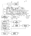
図1は、本発明の一実施例である制御装置が適用されるハイブリッド車両の駆動装置としての変速状態切換型変速機構10(以下、変速機構10という)を説明する骨子図である。図1において、変速機構10は車体に取り付けられる非回転部材としてのトランスミッションケース12(以下、ケース12という)内において共通の軸心上に配設された入力回転部材としての入力軸14と、この入力軸14に直接に或いは図示しない脈動吸収ダンパー(振動減衰装置)などを介して間接に連結された切換型変速部11と、その切換型変速部11と出力軸22との間で伝達部材(伝動軸)18を介して直列に連結されている自動変速機として機能する有段式自動変速部20(以下、自動変速部20という)と、この自動変速部20に連結されている出力回転部材としての出力軸22とを直列に備えている。この変速機構10は、車両において縦置きされるFR(フロントエンジン・リヤドライブ)型車両に好適に用いられるものであり、走行用の駆動力源としてのエンジン8と一対の駆動輪との間に設けられて、図5に示すように動力を差動歯車装置(終減速機)36および一対の車軸等を順次介して一対の駆動輪38へ伝達する。なお、変速機構10はその軸心に対して対称的に構成されているため、図1の変速機構10を表す部分においてはその下側が省略されている。以下の各実施例についても同様である。
FIG. 1 is a skeleton diagram illustrating a shift state switching type transmission mechanism 10 (hereinafter referred to as a transmission mechanism 10) as a drive device for a hybrid vehicle to which a control apparatus according to an embodiment of the present invention is applied. In FIG. 1, a
切換型変速部11は、第1電動機M1と、入力軸14に入力されたエンジン8の出力を機械的に合成し或いは分配する機械的機構であって、エンジン8の出力を第1電動機M1および伝達部材18に分配し、或いはエンジン8の出力とその第1電動機M1の出力とを合成して伝達部材18へ出力させる動力分配機構16と、伝達部材18と一体的に回転するように設けられている第2電動機M2とを備えている。なお、この第2電動機M2は伝達部材18から出力軸22までの間のいずれの部分に設けられてもよい。本実施例の第1電動機M1および第2電動機M2は発電機能をも有する所謂モータジェネレータであるが、第1電動機M1は反力を発生させるためのジェネレータ(発電)機能を少なくとも備え、第2電動機M2は駆動力を出力するためのモータ(電動機)機能を少なくとも備える。
The switching-
動力分配機構16は、例えば「0.418」程度の所定のギヤ比ρ1を有するシングルピニオン型の第1遊星歯車装置24と、切換クラッチC0および切換ブレーキB0とを主体的に備えている。この第1遊星歯車装置24は、第1サンギヤS1、第1遊星歯車P1、その第1遊星歯車P1を自転および公転可能に支持する第1キャリヤCA1、第1遊星歯車P1を介して第1サンギヤS1と噛み合う第1リングギヤR1を回転要素(要素)として備えている。第1サンギヤS1の歯数をZS1、第1リングギヤR1の歯数をZR1とすると、上記ギヤ比ρ1はZS1/ZR1である。
The
この動力分配機構16においては、第1キャリヤCA1は入力軸14すなわちエンジン8に連結され、第1サンギヤS1は第1電動機M1に連結され、第1リングギヤR1は伝達部材18に連結されている。また、切換ブレーキB0は第1サンギヤS1とトランスミッションケース12との間に設けられ、切換クラッチC0は第1サンギヤS1と第1キャリヤCA1との間に設けられている。それら切換クラッチC0および切換ブレーキB0が解放されると、第1サンギヤS1、第1キャリヤCA1、第1リングギヤR1がそれぞれ相互に相対回転可能な状態とされることから、エンジン8の出力が第1電動機M1と伝達部材18とに分配されるとともに、分配されたエンジン8の出力の一部で第1電動機M1から発生させられた電気エネルギで蓄電されたり第2電動機M2が回転駆動されるので、所謂無段変速状態(電気的CVT状態)とされて、エンジン8の所定回転に拘わらず伝達部材18の回転が連続的に変化させられる。すなわち、切換型変速部11がその変速比γ0(入力軸14の回転速度/伝達部材18の回転速度)が最小値γ0min から最大値γ0max まで連続的に変化させられる電気的な無段変速機として機能する無段変速状態とされる。
In the
この状態で、エンジン8の出力で車両走行中に上記切換クラッチC0が係合させられて第1サンギヤS1と第1キャリヤCA1とが一体的に係合させられると、第1遊星歯車装置24の3要素S1、CA1、R1が一体回転することから、エンジン8の回転と伝達部材18の回転速度とが一致する状態となるので、切換型変速部11は変速比γ0が「1」に固定された変速機として機能する定変速状態とされる。次いで、上記切換クラッチC0に替えて切換ブレーキB0が係合させられて第1サンギヤS1が非回転状態とされると、第1リングギヤR1は第1キャリヤCA1よりも増速回転されるので、切換型変速部11は変速比γ0が「1」より小さい値例えば0.7程度に固定された増速変速機として機能する定変速状態とされる。このように、本実施例では、上記切換クラッチC0および切換ブレーキB0は、切換型変速部11を、変速比が連続的変化可能な無段変速機として作動可能な無段変速状態と、無段変速機として作動させず無段変速作動を非作動として変速比変化を一定にロックするロック状態すなわち1または2種類以上の変速比の単段または複数段の変速機として作動可能な定変速状態、換言すれば変速比が一定の1段または複数段の変速機として作動可能な定変速状態とに選択的に切換える作動状態切換装置として機能している。
In this state, when the switching clutch C0 is engaged and the first sun gear S1 and the first carrier CA1 are integrally engaged during traveling of the vehicle with the output of the
自動変速部20は、シングルピニオン型の第2遊星歯車装置26、シングルピニオン型の第3遊星歯車装置28、およびシングルピニオン型の第4遊星歯車装置30を備えている。第2遊星歯車装置26は、第2サンギヤS2、第2遊星歯車P2、その第2遊星歯車P2を自転および公転可能に支持する第2キャリヤCA2、第2遊星歯車P2を介して第2サンギヤS2と噛み合う第2リングギヤR2を備えており、例えば「0.562」程度の所定のギヤ比ρ2を有している。第3遊星歯車装置28は、第3サンギヤS3、第3遊星歯車P3、その第3遊星歯車P3を自転および公転可能に支持する第3キャリヤCA3、第3遊星歯車P3を介して第3サンギヤS3と噛み合う第3リングギヤR3を備えており、例えば「0.425」程度の所定のギヤ比ρ3を有している。第4遊星歯車装置30は、第4サンギヤS4、第4遊星歯車P4、その第4遊星歯車P4を自転および公転可能に支持する第4キャリヤCA4、第4遊星歯車P4を介して第4サンギヤS4と噛み合う第4リングギヤR4を備えており、例えば「0.421」程度の所定のギヤ比ρ4を有している。第2サンギヤS2の歯数をZS2、第2リングギヤR2の歯数をZR2、第3サンギヤS3の歯数をZS3、第3リングギヤR3の歯数をZR3、第4サンギヤS4の歯数をZS4、第4リングギヤR4の歯数をZR4とすると、上記ギヤ比ρ2はZS2/ZR2、上記ギヤ比ρ3はZS3/ZR3、上記ギヤ比ρ4はZS4/ZR4である。
The
自動変速部20では、第2サンギヤS2と第3サンギヤS3とが一体的に連結されて第2クラッチC2を介して伝達部材18に選択的に連結されるとともに第1ブレーキB1を介してケース12に選択的に連結され、第2キャリヤCA2は第2ブレーキB2を介してケース12に選択的に連結され、第4リングギヤR4は第3ブレーキB3を介してケース12に選択的に連結され、第2リングギヤR2と第3キャリヤCA3と第4キャリヤCA4とが一体的に連結されて出力軸22に連結され、第3リングギヤR3と第4サンギヤS4とが一体的に連結されて第1クラッチC1を介して伝達部材18に選択的に連結されている。
In the
前記切換クラッチC0、第1クラッチC1、第2クラッチC2、切換ブレーキB0、第1ブレーキB1、第2ブレーキB2、および第3ブレーキB3は従来の車両用自動変速機においてよく用いられている油圧式摩擦係合装置であって、互いに重ねられた複数枚の摩擦板が油圧アクチュエータにより押圧される湿式多板型や、回転するドラムの外周面に巻き付けられた1本または2本のバンドの一端が油圧アクチュエータによって引き締められるバンドブレーキなどにより構成され、それが介装されている両側の部材を選択的に連結するためのものである。 The switching clutch C0, the first clutch C1, the second clutch C2, the switching brake B0, the first brake B1, the second brake B2, and the third brake B3 are hydraulic types that are often used in conventional automatic transmissions for vehicles. It is a friction engagement device, and a wet multi-plate type in which a plurality of friction plates stacked on each other are pressed by a hydraulic actuator, or one end of one or two bands wound around the outer peripheral surface of a rotating drum It is configured by a band brake or the like tightened by a hydraulic actuator, and is for selectively connecting members on both sides on which the brake is interposed.
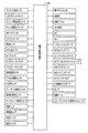
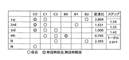
以上のように構成された変速機構10では、例えば、図2の係合作動表に示されるように、前記切換クラッチC0、第1クラッチC1、第2クラッチC2、切換ブレーキB0、第1ブレーキB1、第2ブレーキB2、および第3ブレーキB3が選択的に係合作動させられることにより、第1速ギヤ段(第1変速段)乃至第5速ギヤ段(第5変速段)のいずれか或いは後進ギヤ段(後進変速段)或いはニュートラルが選択的に成立させられ、略等比的に変化する変速比γ(=入力軸回転速度NIN/出力歯車回転速度NOUT )が各ギヤ段毎に得られるようになっている。特に、本実施例では動力分配機構16に切換クラッチC0および切換ブレーキB0が備えられており、切換クラッチC0および切換ブレーキB0の何れかが係合作動させられることによって、切換型変速部11は前述した無段変速機として作動可能な無段変速状態に加え、変速比が一定の変速機として作動可能な定変速状態を構成することが可能とされている。したがって、変速機構10では、切換クラッチC0および切換ブレーキB0の何れかを係合作動させることで定変速状態とされた切換型変速部11と自動変速部20とで有段変速機として作動可能な有段変速状態が構成され、切換クラッチC0および切換ブレーキB0の何れも係合作動させないことで無段変速状態とされた切換型変速部11と自動変速部20とで電気的な無段変速機として作動可能な無段変速状態が構成される。言い換えれば、変速機構10は、切換クラッチC0および切換ブレーキB0の何れかを係合作動させることで有段変速状態に切り換えられ、切換クラッチC0および切換ブレーキB0の何れも係合作動させないことで無段変速状態に切り換えられる。また、切換型変速部11も有段変速状態と無段変速状態とに切り換え可能な変速機であると言える。
In the
例えば、変速機構10が有段変速機として機能する場合には、図2に示すように、切換クラッチC0、第1クラッチC1および第3ブレーキB3の係合により、変速比γ1が最大値例えば「3.357」程度である第1速ギヤ段が成立させられ、切換クラッチC0、第1クラッチC1および第2ブレーキB2の係合により、変速比γ2が第1速ギヤ段よりも小さい値例えば「2.180」程度である第2速ギヤ段が成立させられ、切換クラッチC0、第1クラッチC1および第1ブレーキB1の係合により、変速比γ3が第2速ギヤ段よりも小さい値例えば「1.424」程度である第3速ギヤ段が成立させられ、切換クラッチC0、第1クラッチC1および第2クラッチC2の係合により、変速比γ4が第3速ギヤ段よりも小さい値例えば「1.000」程度である第4速ギヤ段が成立させられ、第1クラッチC1、第2クラッチC2、および切換ブレーキB0の係合により、変速比γ5が第4速ギヤ段よりも小さい値例えば「0.705」程度である第5速ギヤ段が成立させられる。また、第2クラッチC2および第3ブレーキB3の係合により、変速比γRが第1速ギヤ段と第2速ギヤ段との間の値例えば「3.209」程度である後進ギヤ段が成立させられる。なお、ニュートラル「N」状態とする場合には、例えば切換クラッチC0のみが係合される。
For example, when the
しかし、変速機構10が無段変速機として機能する場合には、図2に示される係合表の切換クラッチC0および切換ブレーキB0が共に解放される。これにより、切換型変速部11が無段変速機として機能し、それに直列の自動変速部20が有段変速機として機能することにより、自動変速部20の第1速、第2速、第3速、第4速の各ギヤ段に対しその自動変速部20に入力される回転速度すなわち伝達部材18の回転速度が無段的に変化させられて各ギヤ段は無段的な変速比幅が得られる。したがって、その各ギヤ段の間が無段的に連続変化可能な変速比となって変速機構10全体としてのトータル変速比γTが無段階に得られるようになる。
However, when the
図3は、無段変速部或いは第1変速部として機能する切換型変速部11と有段変速部或いは第2変速部として機能する自動変速部20とから構成される変速機構10において、ギヤ段毎に連結状態が異なる各回転要素の回転速度の相対関係を直線上で表すことができる共線図を示している。この図3の共線図は、横軸方向において各遊星歯車装置24、26、28、30のギヤ比ρの相対関係を示し、縦軸方向において相対的回転速度を示す二次元座標であり、3本の横軸のうちの下側の横線X1が回転速度零を示し、上側の横線X2が回転速度「1.0」すなわち入力軸14に連結されたエンジン8の回転速度NEを示し、横軸XGが伝達部材18の回転速度を示している。また、切換型変速部11を構成する動力分配機構16の3つの要素に対応する3本の縦線Y1、Y2、Y3は、左側から順に第2回転要素(第2要素)RE2に対応する第1サンギヤS1、第1回転要素(第1要素)RE1に対応する第1キャリヤCA1、第3回転要素(第3要素)RE3に対応する第1リングギヤR1の相対回転速度を示すものであり、それらの間隔は第1遊星歯車装置24のギヤ比ρ1に応じて定められている。すなわち、縦線Y1とY2との間隔を1に対応するとすると、縦線Y2とY3との間隔はギヤ比ρ1に対応するものとされる。さらに、自動変速部20の5本の縦線Y4、Y5、Y6、Y7、Y8は、左から順に、第4回転要素(第4要素)RE4に対応し且つ相互に連結された第2サンギヤS2および第3サンギヤS3を、第5回転要素(第5要素)RE5に対応する第2キャリヤCA2を、第6回転要素(第6要素)RE6に対応する第4リングギヤR4を、第7回転要素(第7要素)RE7に対応し且つ相互に連結された第2リングギヤR2、第3キャリヤCA3、第4キャリヤCA4を、第8回転要素(第8要素)RE8に対応し且つ相互に連結された第3リングギヤR3、第4サンギヤS4をそれぞれ表し、それらの間隔は第2、第3、第4遊星歯車装置26、28、30のギヤ比ρ2、ρ3、ρ4に応じてそれぞれ定められている。すなわち、図3に示すように、各第2、第3、第4遊星歯車装置26、28、30毎にそのサンギヤとキャリヤとの間が1に対応するものとされ、キャリヤとリングギヤとの間がρに対応するものとされる。
FIG. 3 shows a gear stage in a
上記図3の共線図を用いて表現すれば、本実施例の変速機構10は、動力分配機構(無段変速部)16において、第1遊星歯車装置24の3回転要素(要素)の1つである第1キャリヤCA1が入力軸14に連結されるとともに切換クラッチC0を介して他の回転要素の1つである第1サンギヤS1と選択的に連結され、その他の回転要素の1つである第1サンギヤS1が第1電動機M1に連結されるとともに切換ブレーキB0を介してトランスミッションケース12に選択的に連結され、残りの回転要素である第1リングギヤR1が伝達部材18および第2電動機M2に連結されて、入力軸14の回転を前記伝達部材18を介して自動変速部(有段変速部)20へ伝達する(入力させる)ように構成されている。このとき、Y2とX2の交点を通る斜めの直線L0により第1サンギヤS1の回転速度と第1リングギヤR1の回転速度との関係が示される。例えば、上記切換クラッチC0および切換ブレーキB0の解放により無段変速状態に切換えられたときは、第1電動機M1の発電による反力を制御することによって直線L0と縦線Y1との交点で示される第1サンギヤS1の回転が上昇或いは下降させられると、直線L0と縦線Y3との交点で示される第1リングギヤR1の回転速度が下降或いは上昇させられる。また、切換クラッチC0の係合により第1サンギヤS1と第1キャリヤCA1とが連結されると、上記3回転要素が一体回転するので、直線L0は横線X2と一致させられ、エンジン回転速度NEと同じ回転で伝達部材18が回転させられる。また、切換ブレーキB0の係合によって第1サンギヤS1の回転が停止させられると、直線L0は図3に示す状態となり、その直線L0と縦線Y3との交点で示される第1リングギヤR1すなわち伝達部材18の回転速度は、エンジン回転速度NEよりも増速された回転で自動変速部20へ入力される。
If expressed using the collinear diagram of FIG. 3 described above, the
自動変速部20では、図3に示すように、第1クラッチC1と第3ブレーキB3とが係合させられることにより、第8回転要素RE8の回転速度を示す縦線Y8と横線X2との交点と第6回転要素RE6の回転速度を示す縦線Y6と横線X1との交点とを通る斜めの直線L1と、出力軸22と連結された第7回転要素RE7の回転速度を示す縦線Y7との交点で第1速の出力軸22の回転速度が示される。同様に、第1クラッチC1と第2ブレーキB2とが係合させられることにより決まる斜めの直線L2と出力軸22と連結された第7回転要素RE7の回転速度を示す縦線Y7との交点で第2速の出力軸22の回転速度が示され、第1クラッチC1と第1ブレーキB1とが係合させられることにより決まる斜めの直線L3と出力軸22と連結された第7回転要素RE7の回転速度を示す縦線Y7との交点で第3速の出力軸22の回転速度が示され、第1クラッチC1と第2クラッチC2とが係合させられることにより決まる水平な直線L4と出力軸22と連結された第7回転要素RE7の回転速度を示す縦線Y7との交点で第4速の出力軸22の回転速度が示される。上記第1速乃至第4速では、切換クラッチC0が係合させられている結果、エンジン回転速度NEと同じ回転速度で第8回転要素RE8に切換型変速部11すなわち動力分配機構16からの動力が入力される。しかし、切換クラッチC0に替えて切換ブレーキB0が係合させられると、切換型変速部11からの動力がエンジン回転速度NEよりも高い回転速度で入力されることから、第1クラッチC1、第2クラッチC2、および切換ブレーキB0が係合させられることにより決まる水平な直線L5と出力軸22と連結された第7回転要素RE7の回転速度を示す縦線Y7との交点で第5速の出力軸22の回転速度が示される。
In the
図4は、本実施例の変速機構10を制御するための電子制御装置40に入力される信号及びその電子制御装置40から出力される信号を例示している。この電子制御装置40は、CPU、ROM、RAM、及び入出力インターフェースなどから成る所謂マイクロコンピュータを含んで構成されており、RAMの一時記憶機能を利用しつつROMに予め記憶されたプログラムに従って信号処理を行うことによりエンジン8、電動機M1、M2に関するハイブリッド駆動制御、前記自動変速部20の変速制御等の駆動制御を実行するものである。
FIG. 4 illustrates a signal input to the
上記電子制御装置40には、図4に示す各センサやスイッチから、エンジン水温を示す信号、シフトポジションを表す信号、エンジン8の回転速度であるエンジン回転速度NE を表す信号、ギヤ比列設定値を示す信号、M(モータ走行)モードを指令する信号、エアコンの作動を示すエアコン信号、出力軸22の回転速度に対応する車速信号、自動変速部20の作動油温を示す油温信号、サイドブレーキ操作を示す信号、フットブレーキ操作を示す信号、触媒温度を示す触媒温度信号、アクセルペダルの操作量を示すアクセル開度信号、カム角信号、スノーモード設定を示すスノーモード設定信号、車両の前後加速度を示す加速度信号、オートクルーズ走行を示すオートクルーズ信号、車両の重量を示す車重信号、各駆動輪の車輪速を示す車輪速信号、変速機構10を有段変速機として機能させるために切換型変速部11を定変速状態に切り換えるための有段スイッチ操作の有無を示す信号、変速機構10を無段変速機として機能させるために切換型変速部11を無段変速状態に切り換えるための無段スイッチ操作の有無を示す信号などが、それぞれ供給される。また、上記電子制御装置40からは、スロットル弁の開度を操作するスロットルアクチュエータへの駆動信号、過給圧を調整するための過給圧調整信号、電動エアコンを作動させるための電動エアコン駆動信号、エンジン8の点火時期を指令する点火信号、電動機M1およびM2の作動を指令する指令信号、シフトインジケータを作動させるためのシフト位置表示信号、ギヤ比を表示させるためのギヤ比表示信号、スノーモードであることを表示させるためのスノーモード表示信号、制動時の車輪のスリップを防止するABSアクチュエータを作動させるためのABS作動信号、Mモードが選択されていることを表示させるMモード表示信号、動力分配機構16や自動変速部20の油圧式摩擦係合装置の油圧アクチュエータを制御するために油圧制御回路42に含まれる電磁弁を作動させるバルブ指令信号、上記油圧制御回路42の油圧源である電動油圧ポンプを作動させるための駆動指令信号、電動ヒータを駆動するための信号、クルーズコントロール制御用コンピュータへの信号等が、それぞれ出力される。
The
図5は、電子制御装置40による制御機能の要部を説明する機能ブロック線図である。図5において、切換制御手段50は、高車速判定手段62、高出力走行判定手段64、および電気パス機能判定手段66を備えており、車両の所定条件に基づいて変速機構10を前記無段変速状態と前記有段変速状態とのいずれかに選択的に切り換える。また、ハイブリッド制御手段52は、変速機構10の前記無段変速状態すなわち切換型変速部11の無段変速状態においてエンジン8を効率のよい作動域で作動させる一方で、エンジン8と第1電動機M1および/または第2電動機M2との駆動力の配分を最適になるように変化させて切換型変速部11の電気的な無段変速機としての変速比γ0を制御する。また、有段変速制御手段54は、例えば変速線図記憶手段56に予め記憶された図6に示す変速線図から車速Vおよび出力トルクTout で示される車両状態に基づいて自動変速部20の変速すべき変速段を判断して自動変速部20の自動変速制御を実行する。
FIG. 5 is a functional block diagram for explaining a main part of the control function by the
高車速判定手段62は、ハイブリッド車両の実際の車速Vが高速走行を判定するための予め設定された高速走行判定値である判定車速V1以上の高車速となったか否かを判定する。高出力走行判定手段64は、ハイブリッド車両の駆動力に関連する駆動力関連値例えば自動変速部20の出力トルクTout が高出力走行を判定するための予め設定された高出力走行判定値である判定出力トルクT1以上の高トルク(高駆動力)走行となったか否かを判定する。電気パス機能判定手段66は、変速機構10を無段変速状態とするための制御機器の機能低下が判定される故障判定条件の判定を、例えば第1電動機M1における電気エネルギの発生からその電気エネルギが機械的エネルギに変換されるまでの電気パスに関連する機器の機能低下すなわち第1電動機M1、第2電動機M2、インバータ58、蓄電装置60、それらを接続する伝送路などの故障や、故障(フェイル)とか低温による機能低下或いは機能不全の発生に基づいて判定する。
The high vehicle speed determination means 62 determines whether or not the actual vehicle speed V of the hybrid vehicle has reached a high vehicle speed equal to or higher than a determination vehicle speed V1 that is a preset high-speed travel determination value for determining high-speed travel. The high output travel determination means 64 determines that the driving force related value related to the driving force of the hybrid vehicle, for example, the output torque Tout of the
上記駆動力関連値とは、車両の駆動力に1対1に対応するパラメータであって、駆動輪38での駆動トルク或いは駆動力のみならず、例えば自動変速部20の出力トルクTout 、エンジントルクTe 、車両加速度や、例えばアクセル開度或いはスロットル開度(或いは吸入空気量、空燃比、燃料噴射量)とエンジン回転速度NEとによって算出されるエンジントルクTe などの実際値や、運転者のアクセルペダル操作量或いはスロットル開度に基づいて算出される要求駆動力等の推定値であってもよい。また、上記駆動トルクは出力トルクTout 等からデフ比、駆動輪38の半径等を考慮して算出されてもよいし、例えばトルクセンサ等によって直接検出されてもよい。上記他の各トルク等も同様である。つまり、高出力走行判定手段64では車両の駆動力を直接或いは間接的に示す駆動力関連パラメータに基づいて車両の高出力走行が判定される。
The driving force-related value is a parameter corresponding to the driving force of the vehicle on a one-to-one basis, and includes not only the driving torque or driving force at the driving
増速側ギヤ段判定手段68は、変速機構10を有段変速状態とする際に切換クラッチC0および切換ブレーキB0のいずれを係合させるかを判定するために、例えば車両状態に基づいて変速線図記憶手段56に予め記憶された図6に示す変速線図に従って変速機構10の変速されるべき変速段が増速側ギヤ段例えば第5速ギヤ段であるか否かを判定する。これは、変速機構10全体が有段式自動変速機として機能させられる場合に、第1速乃至第4速では切換クラッチC0が係合させられ、或いは第5速では切換ブレーキB0が係合させられるようにするためである。
The speed-increasing-side gear
切換制御手段50は、所定条件としての上記高車速判定手段62による高車速判定、高出力走行判定手段64による高出力走行判定すなわち高トルク判定、電気パス機能判定手段66による電気パス機能不全の判定の少なくとも1つが発生した場合は、変速機構10を有段変速状態に切り換える有段変速制御領域であると判定して、ハイブリッド制御手段52に対してハイブリッド制御或いは無段変速制御を不許可すなわち禁止とする信号を出力するとともに、有段変速制御手段54に対しては、予め設定された有段変速時の変速制御を許可する。このときの有段変速制御手段54は、変速線図記憶手段56に予め記憶された例えば図6に示す変速線図に従って自動変速部20の自動変速制御を実行する。図2は、このときの変速制御において選択される油圧式摩擦係合装置すなわちC0、C1、C2、B0、B1、B2、B3の作動の組み合わせを示している。すなわち、変速機構10全体すなわち切換型変速部11および自動変速部20が所謂有段式自動変速機として機能し、図2に示す係合表に従って変速段が達成される。
The switching
例えば、高車速判定手段62による高車速判定、増速側ギヤ段判定手段68による第5速ギヤ段判定、或いは高出力走行判定手段64による高出力走行判定であっても増速側ギヤ段判定手段68により第5速ギヤ段が判定される場合には、変速機構10全体として変速比が1.0より小さな増速側ギヤ段所謂オーバードライブギヤ段が得られるために切換制御手段50は切換型変速部11が固定の変速比γ0例えば変速比γ0が0.7の副変速機として機能させられるように切換クラッチC0を解放させ且つ切換ブレーキB0を係合させる指令を油圧制御回路42へ出力する。また、高出力走行判定手段64による高出力走行判定或いは増速側ギヤ段判定手段68により第5速ギヤ段でないと判定される場合には、変速機構10全体として変速比が1.0以上の減速側ギヤ段が得られるために切換制御手段50は切換型変速部11が固定の変速比γ0例えば変速比γ0が1の副変速機として機能させられるように切換クラッチC0を係合させ且つ切換ブレーキB0を解放させる指令を油圧制御回路42へ出力する。このように、切換制御手段50によって所定条件に基づいて変速機構10が有段変速状態に切り換えられるとともに、その有段変速状態における2種類の変速段のいずれかとなるように選択的に切り換えられて、切換型変速部11が副変速機として機能させられ、それに直列の自動変速部20が有段変速機として機能することにより、変速機構10全体が所謂有段式自動変速機として機能させられる。
For example, even if the high vehicle speed determination by the high vehicle speed determination means 62, the fifth speed gear determination by the acceleration side gear determination means 68, or the high output travel determination by the high output travel determination means 64, the speed increase side gear determination. When the fifth speed gear stage is determined by the
例えば、判定車速V1は、高速走行において変速機構10が無段変速状態とされるとかえって燃費が悪化するのを抑制するように、その高速走行において変速機構10が有段変速状態とされるように設定されている。また、判定トルクT1は、車両の高出力走行において第1電動機M1の反力トルクをエンジンの高出力域まで対応させないで第1電動機M1を小型化するために、例えば第1電動機M1からの電気エネルギの最大出力を小さくして配設可能とされた第1電動機M1の特性に応じて設定されることになる。また、他の考え方として、この高出力走行においては燃費に対する要求より運転者の駆動力に対する要求が重視されるので、無段変速状態より有段変速状態(定変速状態)を選択するのである。これによって、高出力走行では例えば図11に示すような有段自動変速走行におけるアップシフトに伴うエンジン回転速度NEの変化すなわち変速に伴うリズミカルなエンジン回転速度NEの変化が発生する。
For example, the determination vehicle speed V1 is set so that the
しかし、切換制御手段50は、上記高車速判定手段62による高車速判定、高出力走行判定手段64による高出力走行判定、電気パス機能判定手段66による電気パス機能不全の判定のいずれも発生しないときは、変速機構10を無段変速状態に切り換える無段変速制御領域であると判定して、変速機構10全体として無段変速状態が得られるために前記切換型変速部11を無段変速状態として無段変速可能とするように切換クラッチC0および切換ブレーキB0を解放させる指令を油圧制御回路42へ出力する。同時に、ハイブリッド制御手段52に対してハイブリッド制御を許可する信号を出力するとともに、有段変速制御手段54には、予め設定された無段変速時の変速段に固定する信号を出力するか、或いは変速線図記憶手段56に予め記憶された例えば図6に示す変速線図に従って自動変速部20を自動変速することを許可する信号を出力する。この場合、有段変速制御手段54により、図2の係合表内において切換クラッチC0および切換ブレーキB0の係合を除いた作動により自動変速が行われる。このように、切換制御手段50により所定条件に基づいて無段変速状態に切り換えられた切換型変速部11が無段変速機として機能し、それに直列の自動変速部20が有段変速機として機能することにより、適切な大きさの駆動力が得られると同時に、自動変速部20の第1速、第2速、第3速、第4速の各ギヤ段に対しその自動変速部20に入力される回転速度すなわち伝達部材18の回転速度が無段的に変化させられて各ギヤ段は無段的な変速比幅が得られる。したがって、その各ギヤ段の間が無段的に連続変化可能な変速比となって変速機構10全体として無段変速状態となりトータル変速比γTが無段階に得られるようになる。
However, the switching control means 50 does not generate any of the high vehicle speed determination by the high vehicle speed determination means 62, the high output travel determination by the high output travel determination means 64, and the determination of electric path malfunction by the electric path function determination means 66. Is determined to be a continuously variable transmission control region in which the
上記ハイブリッド制御手段52は、エンジン8を効率のよい作動域で作動させる一方で、エンジン8と第1電動機M1および/または第2電動機M2との駆動力の配分を最適になるように変化させる。例えば、そのときの走行車速において、アクセルペダル操作量や車速から運転者の要求出力を算出し、運転者の要求出力と充電要求値から必要な駆動力を算出し、エンジンの回転速度とトータル出力とを算出し、そのトータル出力とエンジン回転速度NEとに基づいて、エンジン出力を得るようにエンジン8を制御するとともに第1電動機M1の発電量を制御する。ハイブリッド制御手段52は、その制御を自動変速部20の変速段を考慮して実行したり、或いは燃費向上などのために自動変速部20に変速指令を行う。このようなハイブリッド制御では、エンジン8を効率のよい作動域で作動させるために定まるエンジン回転速度NEと車速および自動変速部20の変速段で定まる伝達部材18の回転速度とを整合させるために、切換型変速部11が電気的な無段変速機として機能させられる。すなわち、ハイブリッド制御手段52は無段変速走行の時に運転性と燃費性とを両立した予め記憶された最適燃費率曲線に沿ってエンジン8が作動させられるように変速機構10のトータル変速比γTの目標値を定め、その目標値が得られるように切換型変速部11の変速比γ0を制御し、トータル変速比γTをその変速可能な変化範囲内例えば13〜0.5の範囲内で制御することになる。
The hybrid control means 52 operates the
このとき、ハイブリッド制御手段52は、第1電動機M1により発電された電気エネルギをインバータ58を通して蓄電装置60や第2電動機M2へ供給するので、エンジン8の動力の主要部は機械的に伝達部材18へ伝達されるが、エンジン8の動力の一部は第1電動機M1の発電のために消費されてそこで電気エネルギに変換され、インバータ58を通して電気エネルギが第2電動機M2或いは第1電動機M1へ供給され、その第2電動機M2或いは第1電動機M1から伝達部材18へ伝達される。この電気エネルギの発生から第2電動機M2で消費されるまでに関連する機器により、エンジン8の動力の一部を電気エネルギに変換し、その電気エネルギを機械的エネルギに変換するまでの電気パスが構成される。また、ハイブリッド制御手段52は、エンジン8の停止又はアイドル状態に拘わらず、切換型変速部11の電気的CVT機能によってモータ走行させることができる。
At this time, the hybrid control means 52 supplies the electric energy generated by the first electric motor M1 to the
図6は、変速機構10の変速判断の基となる変速線図記憶手段56に予め記憶された変速線図(関係)であり、車速Vと駆動力関連値である出力トルクTout とをパラメータとする二次元座標で構成された変速線図(変速マップ)の一例である。図6の実線はアップシフト線であり一点鎖線はダウンシフト線である。また、図6の破線は切換制御手段50による有段制御領域と無段制御領域との判定のための所定条件を定める判定車速V1および判定出力トルクT1を示しており、高車速判定値である判定車速V1の連なりと高出力走行判定値である判定出力トルクT1の連なりである高車速判定線と高出力走行判定線を示している。さらに、図6の破線に対して二点鎖線に示すように有段制御領域と無段制御領域との判定にヒステリシスが設けられている。この図6は判定車速V1および判定出力トルクT1を含む、車速Vと出力トルクTout とをパラメータとして切換制御手段50により有段制御領域と無段制御領域とのいずれであるかを領域判定するための予め記憶された切換線図(切換マップ、関係)でもある。よって車両の所定条件は、この切換線図から実際の車速Vと出力トルクTout とに基づいて定められてもよい。すなわち、この図6は変速マップと所定条件との関係を示す図であるともいえる。なお、この切換線図を含めて変速マップとして変速線図記憶手段56に予め記憶されてもよい。また、この切換線図は判定車速V1および判定出力トルクT1の少なくとも1つを含むものであってもよいし、車速Vおよび出力トルクTout の何れかをパラメータとする予め記憶された切換線であってもよい。上記変速線図や切換線図等は、実際の車速Vと判定車速V1とを比較する判定式、出力トルクTout と判定出力トルクT1とを比較する判定式等として記憶されてもよい。
FIG. 6 is a shift diagram (relationship) stored in advance in the shift diagram storage means 56, which is a basis for the shift determination of the
前記図6の破線は例えば図7に示すエンジン回転速度NEおよびエンジントルクTEをパラメータとする予め記憶された無段制御領域と有段制御領域との境界線としてのエンジン出力線を有する関係図(マップ)に基づいて自動変速部20の変速線図上に置き直された概念的な切換線である。言い換えれば、図7は図6の破線を作るための概念図である。また切換制御手段50は、この図7の関係図(マップ)から実際のエンジン回転速度NEとエンジントルクTEとに基づいて、それらのエンジン回転速度NEとエンジントルクTEとで表される車両状態が無段制御領域内であるか或いは有段制御領域内であるかを判定してもよい。
The broken line in FIG. 6 has an engine output line as a boundary line between the stepless control region and the stepped control region stored in advance using, for example, the engine speed NE and the engine torque TE shown in FIG. This is a conceptual switching line re-placed on the shift diagram of the
図6の関係に示されるように、出力トルクTout が予め設定された判定出力トルクT1以上の高トルク領域、或いは車速Vが予め設定された判定車速V1以上の高車速領域が、有段制御領域として設定されているので、有段変速走行がエンジン8の比較的高トルクとなる高駆動トルク時、或いは車速の比較的高車速時において実行され、無段変速走行がエンジン8の比較的低トルクとなる低駆動トルク時、或いは車速の比較的低車速時すなわちエンジン8の常用出力域において実行されるようになっている。同様に、図7の関係に示されるように、エンジントルクTEが予め設定された所定値TE1以上の高トルク領域、エンジン回転速度NEが予め設定された所定値NE1以上の高回転領域、或いはそれらエンジントルクTEおよびエンジン回転速度NEから算出されるエンジン出力が所定以上の高出力領域が、有段制御領域として設定されているので、有段変速走行がエンジン8の比較的高トルク、比較的高回転速度、或いは比較的高出力時において実行され、無段変速走行がエンジン8の比較的低トルク、比較的低回転速度、或いは比較的低出力時すなわちエンジン8の常用出力域において実行されるようになっている。図7における有段制御領域と無段制御領域との間の境界線は、高車速判定値の連なりである高車速判定線および高出力走行判定値の連なりである高出力走行判定線に対応している。
As shown in the relationship of FIG. 6, the high torque region where the output torque Tout is equal to or higher than the predetermined determination output torque T1 or the high vehicle speed region where the vehicle speed V is equal to or higher than the predetermined determination vehicle speed V1 is the stepped control region. Therefore, the step-variable traveling is executed at the time of a high driving torque at which the
多重制御判定手段80は、切換制御手段50による変速機構10の変速状態の切換制御すなわち切換型変速部11の変速状態の切換制御の実行と、有段変速制御手段54による自動変速部20の変速制御の実行とが重なるか否かを、例えば切換制御手段50による変速機構10の変速状態の切換制御のための前述した車両の所定条件が成立し、且つ有段変速制御手段54による自動変速部20の変速段の切換が実行されるべき車両状態となったか否かで判定する。本実施例においては、切換制御手段50による切換制御と有段変速制御手段54による変速制御とが重なって実行されることを多重制御と表すこととし、この多重制御にはその切換制御とその変速制御とが同時に開始されるのはもちろんのこと切換制御過程と変速制御過程とがわずかでも重なる場合も含まれる。
The multiplex control determination means 80 performs the shift control of the
図6に示す上矢印はダウンシフト時の多重制御の一例であり、下矢印はアップシフト時の多重制御の一例である。ここでの出力トルクTout は運転者のアクセルペダル操作量に基づいて算出される要求出力トルクTout とする。具体的には、図6の上矢印は変速機構10が無段変速状態であるときにアクセルペダルが踏み込まれたことにより変速機構10の無段変速状態から有段変速状態への切換えと自動変速部20の第3速ギヤ段から第1速ギヤ段へのダウンシフトとの多重制御が発生すること、言い換えれば高出力走行判定手段64による高出力走行判定の成立となる車両状態の無段制御領域から有段制御領域への領域変更が判断され、且つ車両状態が3→2ダウン線および2→1ダウン線を横切ったことで有段変速制御手段54による自動変速部20の変速段の切換えが判断されたことを表している。また、図6の下矢印は変速機構10が有段変速状態であるときにアクセルペダルが戻されたことにより変速機構10の有段変速状態から無段変速状態への切換えと自動変速部20の第3速ギヤ段から第4速ギヤ段へのアップシフトとの多重制御が発生すること、言い換えれば高車速判定手段62による高車速判定、高出力走行判定手段64による高出力走行判定、電気パス機能判定手段66による電気パス機能不全判定のいずれも不成立となる車両状態の有段制御領域から無段制御領域への領域変更が判断され、且つ車両状態が3→4アップ線を横切ったことで有段変速制御手段54による自動変速部20の変速段の切換えが判断されたことを表している。本実施例においては、切換制御手段50による切換制御と有段変速制御手段54によるダウンシフトとが重なって実行されることを多重ダウンと表し、切換制御手段50による切換制御と有段変速制御手段54によるアップシフトとが重なって実行されることを多重アップと表す。従って、多重制御判定手段80は、車両状態が図6の上矢印であるような場合には多重ダウンを判定し、車両状態が図6の下矢印であるような場合には多重アップを判定することになる。
The up arrow shown in FIG. 6 is an example of multiplex control at the time of downshift, and the down arrow is an example of multiplex control at the time of upshift. The output torque Tout here is a required output torque Tout calculated based on the driver's accelerator pedal operation amount. Specifically, the up arrow in FIG. 6 indicates that the
このように、上記多重制御は車両状態の変化例えば図6に示す車速Vとアクセルペダル操作量に基づいて算出される要求出力トルクTout とで表される車両状態の変化で発生することになる。特に、図6から明らかなようにアクセルペダル操作量の変化すなわち要求出力トルクTout の変化で発生しやすいことがわかる。なお、アクセルペダル操作量に替えてスロットル開度等の他の駆動力関連値が用いられてもよい。 As described above, the multiplex control is caused by a change in the vehicle state, for example, a change in the vehicle state represented by the required output torque Tout calculated based on the vehicle speed V and the accelerator pedal operation amount shown in FIG. In particular, as is apparent from FIG. 6, it can be seen that it is likely to occur due to a change in the accelerator pedal operation amount, that is, a change in the required output torque Tout. It should be noted that other driving force related values such as throttle opening may be used instead of the accelerator pedal operation amount.
実行タイミング制御手段82は、切換制御手段50による変速機構10の変速状態の切換制御の実行と有段変速制御手段54による自動変速部20の変速制御の実行とが重なる場合例えば多重制御判定手段80により多重制御が発生すると判定された場合には、その多重制御の発生を回避するためにその切換制御とその変速制御とを予め決められた手順で順次実行させる。すなわち、実行タイミング制御手段82は多重制御が発生する場合には切換制御手段50による切換制御および有段変速制御手段54による変速制御の何れか一方を先に実行させ、その一方の制御が終了した後に他方を順次実行させる、所謂シーケンス制御を実行する。これにより、多重制御の発生が回避され上記切換制御および上記変速制御が速やか実行される。また、変速制御中に切換制御が実行されないので、切換型変速部11から自動変速部20へ入力される回転速度すなわち伝達部材18の回転速度が変速制御に伴う回転速度変化とは別に変化してしまうことによって変速制御が複雑化することが回避されて変速ショックの悪化が抑制される。このシーケンス制御における上記切換制御および上記変速制御の何れの制御を先に実行するかを定める予め決められた手順について以下に具体的に説明する。
The execution timing control means 82 is, for example, a multiplex control determination means 80 when the execution of the shift control of the
例えば、実行タイミング制御手段82は、一律に切換制御手段50による変速機構10の変速状態の切換制御を先に実行させる。これにより、例えば切換制御手段50による変速機構10の無段変速状態から有段変速状態への切換制御が実行された後に有段変速制御手段54による自動変速部20の変速制御が実行されるので、有段変速状態(定変速状態)とされた切換型変速部11においてエンジン回転速度NEに対する相対的な伝達部材18の回転速度が固定された状態すなわち自動変速部20への入力回転速度が安定した状態で自動変速部20の変速制御が実行されることになり多重制御に比較して変速制御の複雑化が回避され変速制御が速やかに実行されて変速ショックの悪化が抑制される。また、切換制御手段50による変速機構10の有段変速状態から無段変速状態への切換制御が実行された後に有段変速制御手段54による自動変速部20の変速制御が実行されるので、自動変速部20の変速に伴って変化する自動変速部20への入力回転速度すなわち伝達部材18の回転速度が無段変速状態とされた切換型変速部11によって速やかに変化させられることになり自動変速部20の変速制御が速やかに実行されて変速ショックの悪化が抑制される。
For example, the execution
或いは、また、実行タイミング制御手段82は、一律に有段変速制御手段54による変速制御を先に実行させる。これにより、例えば変速機構10の有段変速状態において有段変速制御手段54による自動変速部20の変速制御が実行された後に切換制御手段50による変速機構10の有段変速状態から無段変速状態への切換制御が実行されるので、有段変速状態が維持されている切換型変速部11におけるエンジン回転速度NEに対する相対的な伝達部材18の回転速度が固定された状態すなわち自動変速部20への入力回転速度が安定している状態で自動変速部20の変速制御が実行されることになり多重制御に比較して変速制御の複雑化が回避され変速制御が速やかに実行されて変速ショックの悪化が抑制される。また、変速機構10の無段変速状態において有段変速制御手段54による自動変速部20の変速制御が実行された後に切換制御手段50による変速機構10の無段変速状態から有段変速状態への切換制御が実行されるので、自動変速部20の変速に伴って変化する自動変速部20への入力回転速度すなわち伝達部材18の回転速度が無段変速状態が維持されている切換型変速部11によって速やかに変化させられることになり自動変速部20の変速制御が速やかに実行されて変速ショックの悪化が抑制される。
Alternatively, the execution timing control means 82 uniformly executes the shift control by the stepped shift control means 54 first. Thereby, for example, after the shift control of the
或いは、また、実行タイミング制御手段82は、車両状態に基づいて切換制御手段50による変速機構10の変速状態の切換制御と有段変速制御手段54による自動変速部20の変速制御との何れを先に実行させるかを判断し、実行させる。例えば、前述したように図6の下矢印に示すようにアクセルペダルの戻し操作に伴って車両状態が変化して多重アップが発生する場合には、実行タイミング制御手段82は変速機構10の有段変速状態を維持した状態で有段変速制御手段54による変速制御を先に実行させる。これにより、上記同様に自動変速部20の変速ショックの悪化が抑制される。この多重アップの場合には、実行タイミング制御手段82は切換制御手段50による変速機構10の無段変速状態への切換制御を先に実行させてもよい。これにより、上記同様に自動変速部20の変速ショックの悪化が抑制される。また、前述したように図6の上矢印に示すようにアクセルペダルの踏み込み操作に伴って車両状態が変化して多重ダウンが発生する場合には、第1電動機M1の小型化に伴い第1電動機M1の伝える電気的エネルギが小さいためにエンジンの高出力域まで対応させられないこともあり実行タイミング制御手段82は切換制御手段50による変速機構10の有段変速状態への切換制御を先に実行させる。このことは、実行タイミング制御手段82は、車両状態に基づいて切換制御手段50による変速機構10の変速状態の切換制御と有段変速制御手段54による自動変速部20の変速制御との何れを先に実行させるかの予め決められた手順を変更するとも言える。これにより、上記同様に自動変速部20の変速ショックの悪化が抑制される。但し、第1電動機M1がエンジンの高出力域まで対応させられる場合には、実行タイミング制御手段82は変速機構10の無段変速状態を維持した状態で有段変速制御手段54による変速制御を先に実行させてもよい。これにより、上記同様に自動変速部20の変速ショックの悪化が抑制される。このようにアクセルペダルの操作に伴って発生する多重制御においてアクセルペダル戻しの場合は要求出力トルクTout 減少による変速機構10の有段変速状態から無段変速状態への切換えであり、アクセルペダル踏み込みの場合は要求出力トルクTout 増加による変速機構10の無段変速状態から有段変速状態への切換えであるので、実行タイミング制御手段82は、車両状態を変化させるパラメータとなる車両の走行条件としてのアクセルペダル操作量に基づいて切換制御手段50による変速機構10の変速状態の切換制御と有段変速制御手段54による自動変速部20の変速制御との何れを先に実行させるかを判断するとも言える。上記車両の走行条件はアクセルペダル操作量の他にスロットル開度等の他の駆動力関連値や車速V、油温等である。
Alternatively, the execution
或いは、また、実行タイミング制御手段82は、変速機構10が前記無段変速状態と前記有段変速状態とのいずれの変速状態であるかに基づいて切換制御手段50による変速機構10の変速状態の切換制御と有段変速制御手段54による自動変速部20の変速制御との何れを先に実行させるかを判断し、実行させる。例えば、実行タイミング制御手段82は変速機構10が無段変速状態の場合には先に切換制御手段50による変速機構10の無段変速状態から有段変速状態への切換制御を実行させ、或いは変速機構10が有段変速状態の場合には先に有段変速制御手段54による変速制御を実行させる。これにより、変速機構10の有段変速状態で自動変速部20の変速が実行されるので上記同様に自動変速部20の変速ショックの悪化が抑制される。また、実行タイミング制御手段82は変速機構10が無段変速状態の場合には先に有段変速制御手段54による変速制御を実行させ、或いは変速機構10が有段変速状態の場合には先に切換制御手段50による変速機構10の有段変速状態から無段変速状態への切換制御を実行させてもよい。これにより、変速機構10の無段変速状態で自動変速部20の変速が実行されるので上記同様に自動変速部20の変速ショックの悪化が抑制される。
Alternatively, the execution timing control means 82 may determine the speed change state of the
或いは、また、実行タイミング制御手段82は、変速機構10が前記無段変速状態と前記有段変速状態とのいずれの変速状態に切り換えられる予定であるかに基づいて切換制御手段50による変速機構10の変速状態の切換制御と有段変速制御手段54による自動変速部20の変速制御との何れを先に実行させるかを判断し、実行させる。例えば、実行タイミング制御手段82は変速機構10が無段変速状態へ切り換えられる場合には先に有段変速制御手段54による変速制御を実行させ、或いは変速機構10が有段変速状態へ切り換えられる場合には先に切換制御手段50による変速機構10の無段変速状態から有段変速状態への切換制御を実行させる。これにより、変速機構10の有段変速状態で自動変速部20の変速が実行されるので上記同様に自動変速部20の変速ショックの悪化が抑制される。また、実行タイミング制御手段82は変速機構10が無段変速状態へ切り換えられる場合には先に切換制御手段50による変速機構10の有段変速状態から無段変速状態への切換制御を実行させ、或いは変速機構10が有段変速状態へ切り換えられる場合には先に有段変速制御手段54による変速制御を実行させてもよい。これにより、変速機構10の無段変速状態で自動変速部20の変速が実行されるので上記同様に自動変速部20の変速ショックの悪化が抑制される。
Alternatively, the execution timing control means 82 is configured to change the
或いは、また、実行タイミング制御手段82は、切換制御手段50による切換制御と有段変速制御手段54による変速制御とのいずれか一方がすでに開始されている場合には、その一方の制御が終了した後に他方の制御を実行させる。これにより、切換制御手段50による切換制御と有段変速制御手段54による変速制御とがシーケンス制御されるので、上記同様に自動変速部20の変速ショックの悪化が抑制される。
Alternatively, when one of the switching control by the switching
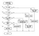
図8は、電子制御装置40の制御作動の要部を説明するフローチャートであり、例えば数msec乃至数十msec程度の極めて短いサイクルタイムで繰り返し実行されるものである。また、図9は3速→1速の多重ダウンが発生するときの、図10は3速→4速の多重アップが発生するときのそれぞれの制御作動を説明するタイムチャートである。
FIG. 8 is a flowchart for explaining a main part of the control operation of the
先ず、多重制御判定手段80に対応するステップ(以下、ステップを省略する)S1およびS2において、切換制御手段50による変速機構10の変速状態の切換制御と、有段変速制御手段54による自動変速部20の変速制御とが重なる多重制御が発生したか否かが判定される。例えば、S1においてアクセルペダル操作量の変化に伴って車両状態が変化してダウンシフトの多重制御が発生するか否かが判定され、S2においてアクセルペダル操作量の変化に伴って車両状態が変化してアップシフトの多重制御が発生するか否かが判定される。例えば車両状態が図6の上矢印のように変化する場合にはS1の判断が肯定され、或いは車両状態が図6の下矢印のように変化する場合にはS2の判断が肯定される。
First, in steps (hereinafter, steps are omitted) S1 and S2 corresponding to the multiple control determination means 80, the shift control of the
上記S1の判断が肯定される場合は切換制御手段50に対応するS6において、図9のt1時点乃至t3時点に無段ロックとして示した変速機構10の無段変速状態から有段変速状態への切換えが先ず実行される。この場合の切換制御では、自動変速部20のギヤ段が第1速ギヤ段への変速であるので或いは要求出力トルクTout が判定出力トルクT1以上であるので切換クラッチC0が係合させられる。これにより、自動変速部20の入力回転速度がエンジン回転速度NEに固定されたことになる。このとき第1電動機M1や第2電動機M2によってエンジン回転速度NEが変化させられてもよい。続いて、有段変速制御手段54に対応するS7において、図2の作動表に従って自動変速部20の第1速ギヤ段への自動変速制御が実行される(図9のt2時点乃至t4時点)。従って、多重ダウンが回避され速やかに変速制御が実行されて変速ショックの悪化が抑制される。ここで、図9のt3時点乃至t4時点に見られる出力トルクTout の上昇による変速ショックを抑制するために自動変速部20への入力トルクが低減されてもよい。例えば、図9のt3時点乃至t4時点において第1電動機M1や第2電動機M2による逆駆動トルクや回生制動トルクの発生、エンジン8の燃料供給量や点火時期制御によるエンジントルクダウン制御により自動変速部20への入力トルクが低減される。また、図9の破線は実線に比較してアクセルペダルがゆっくり踏み込まれた場合で、ダウンシフトの変速時間を長くした場合すなわちゆっくりダウンさせた場合の実施例である(図9のt2時点乃至t5時点)。また、図8のS6とS7、および図9は変速機構10の無段変速状態から有段変速状態への切換えとダウンシフトとの多重制御が発生する場合の実施例であったが、変速前が有段変速状態でダウンシフト後が無段変速状態となる多重制御が発生する場合には自動変速部20の変速を先に実行してその後変速機構10が無段変速状態に切り換えられてもよい。
In S6 judgment corresponding to the switching control means 50 if the result is affirmative in the S1, the step-variable shifting state from the continuously-variable shifting state of the
前記S1の判断が否定され且つ前記S2の判断が肯定される場合は有段変速制御手段54に対応するS8において、図10のt1時点に示したアップシフト指令以降に図2の作動表に従って自動変速部20の第4速ギヤ段への自動変速制御が先ず実行される(図10のt2時点乃至t4時点)。これにより、自動変速部20の入力回転速度がエンジン回転速度NEに固定された状態が維持されて変速制御が実行される。ここで、図10のt3時点乃至t4時点に見られる変速制御中のイナーシャトルクの発生による変速ショックを抑制するために自動変速部20への入力トルクが低減されてもよい。例えば、図10のt3時点乃至t4時点において第1電動機M1や第2電動機M2による逆駆動トルクや回生制動トルクの発生、エンジン8の燃料供給量や点火時期制御によるエンジントルクダウン制御により自動変速部20への入力トルクが低減される。また、反対に図10のt4時点から第1電動機M1や第2電動機M2による駆動トルクの発生、エンジン8の燃料供給量制御等によるエンジントルクアップ制御により自動変速部20への入力トルクが増加されてもよい。続いて、切換制御手段50に対応するS9において、変速機構10の有段変速状態から無段変速状態への切換えが実行される(図10のt4時点乃至t5時点)。この場合の切換制御では、自動変速部20のギヤ段が第4速ギヤ段となっているので切換クラッチC0が解放させられる。従って、多重アップが回避され速やかに変速制御が実行されて変速ショックの悪化が抑制される。また、図10の破線は実線に比較して変速ショックが低減されるためにアップシフトの変速時間を長くした場合すなわちゆっくりアップさせた場合の実施例である(図10のt2時点乃至t6時点)。この場合には、図10のt6時点以降で変速機構10の有段変速状態から無段変速状態への切換えが実行される。また、図8のS8とS9、および図10は変速機構10のアップシフトと有段変速状態から無段変速状態への切換えとの多重制御が発生する場合の実施例であったが、変速前が無段変速状態でアップシフト後が有段変速状態となる多重制御が発生する場合には変速機構10の有段変速状態への切換えを先に実行してその後自動変速部20が変速されてもよい。
In S8 corresponding to the step-variable shifting control means 54 when the determination in S1 is determined in the negative and the S2 is affirmative, in accordance with the operation table of FIG 2 after upshift command shown in time point t 1 in FIG. 10 automatic shift control to the fourth gear of the
前記S1およびS2の判断がともに否定される場合は切換制御手段50に対応するS3において、単独で変速機構10の前記無段変速状態と前記有段変速状態との間の切換えが判定されたか否かが、例えば車両の所定条件に基づいて変速機構10が前記無段変速状態と前記有段変速状態とのいずれかに選択的に切り換えられるか否かで判断される。このS3の判断が肯定される場合は同じく切換制御手段50に対応するS10において、変速機構10が前記無段変速状態と前記有段変速状態とのいずれかに選択的に切り換えられる。例えば、S3において有段変速状態から無段変速状態への切換が判断された場合は、変速機構10が無段変速状態とされるように切換クラッチC0および切換ブレーキB0を解放させる指令が油圧制御回路42へ出力されるとともにハイブリッド制御手段52に対してハイブリッド制御を許可する信号が出力される。或いは、S3において無段変速状態から有段変速状態への切換が判断された場合は、変速機構10が有段変速状態とされるように自動変速部20のギヤ段が第1速乃至第4速では、切換クラッチC0が係合させられる、或いは第5速では、その切換クラッチC0の係合に替えて切換ブレーキB0が係合させられるとともにハイブリッド制御手段52に対してハイブリッド制御或いは無段変速制御を不許可(禁止)とする信号が出力される。ここでの変速機構10が有段変速状態とされるための切換クラッチC0の係合或いは切換ブレーキB0の係合は、図6の関係図から出力トルクTout が判定出力トルクT1以上では切換クラッチC0が係合させられ、或いは車速Vが判定車速V1以上では切換ブレーキB0が係合させられてもよい。
If both the determinations of S1 and S2 are negative, in S3 corresponding to the switching control means 50, whether or not switching of the
上記S3の判断が否定される場合は有段変速制御手段54に対応するS4において、自動変速部20の変速段の切換えが判断されたか否かが、例えば図6に示す変速線図において車両状態が変速線を横切る状態となったか否かで判断される。このS4の判断が肯定される場合は同じく有段変速制御手段54に対応するS11において、変速線図記憶手段56に予め記憶された例えば図6に示す変速線図に従って自動変速制御が実行される。図2は、このときの変速制御において選択される油圧式摩擦係合装置すなわちC0、C1、C2、B0、B1、B2、B3の作動の組み合わせを示している。上記S4の判断が否定される場合はS5において現在の車両走行状態が維持される。
If the determination in S3 is negative, it is determined in S4 corresponding to the stepped shift control means 54 whether or not switching of the shift stage of the
上述のように、本実施例によれば、電気的な無段変速機として作動可能な無段変速状態と有段の変速機として作動可能な有段変速状態とに切り換え可能な変速機構10における切換制御手段50(S6、S9)による切換制御と、自動変速部20における有段変速制御手段54(S7、S8)による変速制御とが重なって実行される場合には、実行タイミング制御手段82(S1、S2)によって前記切換制御と前記変速制御とが順次実行させられるので、前記切換制御と前記変速制御とが重なって実行されることが回避されそれぞれの制御が速やか実行される。また、有段変速制御手段54による自動変速部20の変速制御中には切換制御手段50による変速機構10の変速状態の切換えが実行されないので、例えば自動変速部20へ入力される回転速度が変速制御に伴う回転速度変化とは別に変化してしまうことによる変速制御の複雑化が回避されて変速ショックの悪化が抑制される。
As described above, according to the present embodiment, in the
また、本実施例によれば、実行タイミング制御手段82は、切換制御手段50による切換制御を先に実行させるものであるので、前記切換制御と前記変速制御とが重なって実行されることが回避される。例えば、切換制御手段50による変速機構10の無段変速状態から有段変速状態への切換制御が実行させられた後に有段変速制御手段54による自動変速部20の変速制御が実行させられた場合は、自動変速部20への入力回転速度が安定した状態で自動変速部20の変速制御が実行されることになり変速制御の複雑化が回避され変速制御が速やかに実行されて変速ショックが抑制される。また、切換制御手段50による変速機構10の有段変速状態から無段変速状態への切換制御が実行させられた後に有段変速制御手段54による自動変速部20の変速制御が実行させられた場合は、自動変速部20への入力回転速度が無段変速状態となった変速機構10すなわち切換型変速部11によって速やかに変化させられて自動変速部20の変速制御が速やかに実行されて変速ショックの悪化が抑制される。
Further, according to the present embodiment, the execution timing control means 82 is to execute the switching control by the switching control means 50 first, so that the switching control and the shift control are prevented from being executed in an overlapping manner. Is done. For example, when the shift control of the
また、本実施例によれば、実行タイミング制御手段82は、有段変速制御手段54による変速制御を先に実行させるものであるので、前記切換制御と前記変速制御とが重なって実行されることが回避される。例えば、変速機構10の有段変速状態で有段変速制御手段54による自動変速部20の変速制御が実行させられた後に切換制御手段50による変速機構10の有段変速状態から無段変速状態への切換制御が実行させられた場合は、自動変速部20への入力回転速度が安定している状態で自動変速部20の変速制御が実行されることになり変速制御の複雑化が回避され変速制御が速やかに実行されて変速ショックが抑制される。また、変速機構10の無段変速状態で変速制御手段による自動変速部20の変速制御が実行させられた後に切換制御手段50による変速機構20の無段変速状態から有段変速状態への切換制御が実行させられた場合は、自動変速部20への入力回転速度が無段変速状態となっている変速機構10すなわち切換型変速部11によって速やかに変化させられて自動変速部20の変速制御が速やかに実行されて変速ショックの悪化が抑制される。
Further, according to the present embodiment, the execution timing control means 82 is to execute the shift control by the stepped shift control means 54 first, so that the switching control and the shift control are executed in an overlapping manner. Is avoided. For example, after the speed change control of the
また、本実施例によれば、実行タイミング制御手段82は、車両状態に基づいて切換制御手段50による切換制御と有段変速制御手段54による変速制御との何れを先に実行させるかを変更するものであるので、前記切換制御と前記変速制御とが重なって実行されることが車両状態に合わせて適切に回避される。 Further, according to the present embodiment, the execution timing control means 82 changes which of the switching control by the switching control means 50 and the shift control by the stepped shift control means 54 is executed first based on the vehicle state. Therefore, it is possible to appropriately avoid the switching control and the shift control from being executed in accordance with the vehicle state.
また、本実施例によれば、実行タイミング制御手段82は、変速機構10が前記無段変速状態と前記有段変速状態とのいずれの変速状態であるかに基づいて切換制御手段50による切換制御と有段変速制御手段54による変速制御との何れを先に実行させるかを判断するものであるので、前記切換制御と前記変速制御とが重なって実行されることが回避される。
Further, according to the present embodiment, the execution timing control means 82 is controlled by the switching control means 50 based on whether the
また、本実施例によれば、実行タイミング制御手段82は、変速機構10が前記無段変速状態と前記有段変速状態とのいずれの変速状態に切り換えられるかに基づいて切換制御手段50による切換制御と有段変速制御手段54による変速制御との何れを先に実行させるかを判断するものであるので、前記切換制御と前記変速制御とが重なって実行されることが回避される。
Further, according to this embodiment, the execution timing control means 82 is switched by the switching control means 50 based on whether the
また、本実施例によれば、実行タイミング制御手段82は、変速機構10が前記有段変速状態から前記無段変速状態へ切り換わる場合と前記無段変速状態から前記有段変速状態へ切り換わる場合とで切換制御手段50による切換制御と有段変速制御手段54による変速制御との何れを先に実行させるかを判断するものでもあるので、前記切換制御と前記変速制御とが重なって実行されることが回避される。
Further, according to the present embodiment, the execution timing control means 82 switches between the case where the
また、本実施例によれば、車両の所定条件は、予め設定された高速走行判定値である判定車速V1に基づいて定められたものであり、切換制御手段50は実際の車速Vがその判定車速V1を越えたときに変速機構10を有段変速状態とするものであるので、例えば実際の車速Vが高車速側に設定された判定車速V1を越えるような高速走行となると、専ら機械的な動力伝達経路でエンジン8の出力が駆動輪38へ伝達されて変速機構10が電気的な無段変速機として作動させられる場合に発生する動力と電気エネルギとの間の変換損失が抑制されるので燃費が向上させられる。
Further, according to the present embodiment, the predetermined condition of the vehicle is determined based on the determination vehicle speed V1, which is a preset high-speed traveling determination value, and the switching control means 50 determines that the actual vehicle speed V is the determination. When the vehicle speed V1 is exceeded, the
また、本実施例によれば、車両の所定条件は、予め設定された高出力走行判定値である判定出力トルクT1に基づいて定められたものであり、切換制御手段50は実際の出力トルクTout がその判定出力トルクT1を越えたときに変速機構10を有段変速状態とするものであるので、例えば実際の出力トルクTout が高出力側に設定された判定出力トルクT1を越えるような高出力走行となると、専ら機械的な動力伝達経路でエンジン8の出力が駆動輪38へ伝達されて変速機構10が電気的な無段変速機として作動させられる場合は専ら低中出力走行となるので、第1電動機M1が発生すべき電気的エネルギの最大値を小さくできてすなわち第1電動機M1の保障すべき出力容量を小さくできてその第1電動機M1や第2電動機M2、或いはそれを含む車両の駆動装置が一層小型化される。
Further, according to the present embodiment, the predetermined condition of the vehicle is determined based on the determination output torque T1 that is a preset high output travel determination value, and the switching control means 50 determines the actual output torque Tout. Since the
また、本実施例によれば、車両の所定条件は、判定車速V1および判定出力トルクT1を含む、車速Vと出力トルクTout とをパラメータとする予め記憶された切換線図から実際の車速Vと出力トルクTout とに基づいて定められるものであるので、切換制御手段50による高車速判定または高出力走行判定が簡単に判定される。 Further, according to the present embodiment, the predetermined condition of the vehicle is that the actual vehicle speed V and the actual vehicle speed V are determined from the switching diagram stored in advance using the vehicle speed V and the output torque Tout as parameters, including the determination vehicle speed V1 and the determination output torque T1. Since it is determined based on the output torque Tout, the high vehicle speed determination or the high output traveling determination by the switching control means 50 is easily determined.
また、本実施例によれば、車両の所定条件は、変速機構10を無段変速状態とするための制御機器の機能低下を判定する故障判定条件であり、切換制御手段50はその故障判定条件が成立した場合に変速機構10を有段変速状態とするものであるので、変速機構10が無段変速状態とされない場合でも有段変速状態とされることで、有段走行ではあるが無段走行と略同様の車両走行が確保される。
Further, according to the present embodiment, the predetermined condition of the vehicle is a failure determination condition for determining a functional deterioration of the control device for setting the
また、本実施例によれば、動力分配機構16が、第1キャリヤCA1、第1サンギヤS1、第1リングギヤR1を3要素とするシングルピニオン型の第1遊星歯車装置24によって簡単に且つ動力分配機構16の軸方向寸法が小さく構成される利点がある。さらに、動力分配機構16には油圧式摩擦係合装置すなわち第1サンギヤS1と第1キャリヤCA1とを相互に連結する切換クラッチC0および第1サンギヤS1をトランスミッションケース12に連結する切換ブレーキB0が設けられているので、切換制御手段50により変速機構10の無段変速状態と有段変速状態とが簡単に制御される。
In addition, according to the present embodiment, the
また、本実施例によれば、動力分配機構16と駆動輪38との間に自動変速部20が直列に介装されており、その動力分配機構16の変速比すなわち切換型変速部11の変速比とその自動変速部20の変速比とに基づいて変速機構10の総合変速比が形成されることから、その自動変速部20の変速比を利用することによって駆動力が幅広く得られるようになるので、切換型変速部11における無段変速制御すなわちハイブリッド制御の効率が一層高められる。
Further, according to the present embodiment, the
また、本実施例によれば、変速機構10が有段変速状態とされるとき、切換型変速部11が自動変速部20の一部であるかの如く機能して変速比が1より小さいオーバドライブギヤ段である第5速が得られる利点がある。
Further, according to this embodiment, when the
また、本実施例によれば、切換制御手段50(S10)は、車両の所定条件に基づいて変速機構10を前記無段変速状態と前記有段変速状態とのいずれかに自動的に切り換えられることから、電気的な無段変速機の燃費改善効果と機械的に動力を伝達する有段変速機の高い伝達効率との両長所を兼ね備えた駆動装置が得られる。すなわち、エンジンの常用出力域例えば図7に示す無段制御領域或いは図6に示す車速Vが判定車速V1以下且つ出力トルクTout が判定出力トルクT1以下となる無段制御領域では変速機構10が無段変速状態とされてハイブリッド車両の通常の市街地走行すなわち車両の低中速走行および低中出力走行での燃費性能が確保されると同時に、高速走行例えば図6に示す車速Vが判定車速V1以上となる有段制御領域では変速機構10が有段変速状態とされ専ら機械的な動力伝達経路でエンジン8の出力が駆動輪38へ伝達されて無段変速状態とされた場合の動力と電気エネルギとの間の変換損失が抑制されるので、燃費が向上させられる。また、高出力走行例えば図6に示す実際の出力トルクTout が判定出力トルクT1以上となる有段制御領域では変速機構10が有段変速状態とされ専ら機械的な動力伝達経路でエンジン8の出力が駆動輪38へ伝達されて無段変速状態として作動させる領域が車両の低中速走行および低中出力走行となるので、第1電動機M1が発生すべき電気的エネルギすなわちが第1電動機M1が伝える電気的エネルギの最大値を小さくできてその第1電動機M1や第2電動機M2、或いはそれを含む車両の駆動装置が一層小型化される。
Further, according to the present embodiment, the switching control means 50 (S10) automatically switches the
また、本実施例によれば、第2電動機M2が自動変速部20の入力回転部材である伝達部材18に連結されていることから、その自動変速部20の出力軸22に対して低トルクの出力でよくなるので、第2電動機M2が一層小型化される利点がある。
Further, according to the present embodiment, since the second electric motor M2 is connected to the
次に、本発明の他の実施例を説明する。なお、以下の説明において前述の実施例と共通する部分には同一の符号を付して説明を省略する。 Next, another embodiment of the present invention will be described. In the following description, parts common to those in the above-described embodiment are denoted by the same reference numerals and description thereof is omitted.
図12は本発明の他の実施例における変速機構70の構成を説明する骨子図、図13はその変速機構70の変速段と油圧式摩擦係合装置の係合の組み合わせとの関係を示す係合表、図14はその変速機構70の変速作動を説明する共線図である。
FIG. 12 is a skeleton diagram illustrating the configuration of the
変速機構70は、前述の実施例と同様に第1電動機M1、動力分配機構16、および第2電動機M2を備えている切換型変速部11と、その切換型変速部11と出力軸22との間で伝達部材18を介して直列に連結されている前進3段の自動変速部72とを備えている。動力分配機構16は、例えば「0.418」程度の所定のギヤ比ρ1を有するシングルピニオン型の第1遊星歯車装置24と切換クラッチC0および切換ブレーキB0とを有している。自動変速部72は、例えば「0.532」程度の所定のギヤ比ρ2を有するシングルピニオン型の第2遊星歯車装置26と例えば「0.418」程度の所定のギヤ比ρ3を有するシングルピニオン型の第3遊星歯車装置28とを備えている。第2遊星歯車装置26の第2サンギヤS2と第3遊星歯車装置28の第3サンギヤS3とが一体的に連結されて第2クラッチC2を介して伝達部材18に選択的に連結されるとともに第1ブレーキB1を介してケース12に選択的に連結され、第2遊星歯車装置26の第2キャリヤCA2と第3遊星歯車装置28の第3 リングギヤR3とが一体的に連結されて出力軸22に連結され、第2リングギヤR2は第1クラッチC1を介して伝達部材18に選択的に連結され、第3キャリヤCA3は第2ブレーキB2を介してケース12に選択的に連結されている。
As in the above-described embodiment, the
以上のように構成された変速機構70では、例えば、図13の係合作動表に示されるように、前記切換クラッチC0、第1クラッチC1、第2クラッチC2、切換ブレーキB0、第1ブレーキB1、および第2ブレーキB2が選択的に係合作動させられることにより、第1速ギヤ段(第1変速段)乃至第4速ギヤ段(第4変速段)のいずれか或いは後進ギヤ段(後進変速段)或いはニュートラルが選択的に成立させられ、略等比的に変化する変速比γ(=入力軸回転速度NIN/出力歯車回転速度NOUT )が各ギヤ段毎に得られるようになっている。特に、本実施例では動力分配機構16に切換クラッチC0および切換ブレーキB0が備えられており、切換クラッチC0および切換ブレーキB0の何れかが係合作動させられることによって、切換型変速部11は前述した無段変速機として作動可能な無段変速状態に加え、変速比が一定の変速機として作動可能な定変速状態を構成することが可能とされている。したがって、変速機構70では、切換クラッチC0および切換ブレーキB0の何れかを係合作動させることで定変速状態とされた切換型変速部11と自動変速部72とで有段変速機として作動可能な有段変速状態が構成され、切換クラッチC0および切換ブレーキB0の何れも係合作動させないことで無段変速状態とされた切換型変速部11と自動変速部72とで電気的な無段変速機として作動可能な無段変速状態が構成される。言い換えれば、変速機構70は、切換クラッチC0および切換ブレーキB0の何れかを係合作動させることで有段変速状態に切り換えられ、切換クラッチC0および切換ブレーキB0の何れも係合作動させないことで無段変速状態に切り換えられる。
In the
例えば、変速機構70が有段変速機として機能する場合には、図13に示すように、切換クラッチC0、第1クラッチC1および第2ブレーキB2の係合により、変速比γ1が最大値例えば「2.804」程度である第1速ギヤ段が成立させられ、切換クラッチC0、第1クラッチC1および第1ブレーキB1の係合により、変速比γ2が第1速ギヤ段よりも小さい値例えば「1.531」程度である第2速ギヤ段が成立させられ、切換クラッチC0、第1クラッチC1および第2クラッチC2の係合により、変速比γ3が第2速ギヤ段よりも小さい値例えば「1.000」程度である第3速ギヤ段が成立させられ、第1クラッチC1、第2クラッチC2、および切換ブレーキB0の係合により、変速比γ4が第3速ギヤ段よりも小さい値例えば「0.705」程度である第4速ギヤ段が成立させられる。また、第2クラッチC2および第2ブレーキB2の係合により、変速比γRが第1速ギヤ段と第2速ギヤ段との間の値例えば「2.393」程度である後進ギヤ段が成立させられる。なお、ニュートラル「N」状態とする場合には、例えば切換クラッチC0のみが係合される。
For example, when the
しかし、変速機構70が無段変速機として機能する場合には、図13に示される係合表の切換クラッチC0および切換ブレーキB0が共に解放される。これにより、切換型変速部11が無段変速機として機能し、それに直列の自動変速部72が有段変速機として機能することにより、自動変速部72の第1速、第2速、第3速の各ギヤ段に対しその自動変速部72に入力される回転速度すなわち伝達部材18の回転速度が無段的に変化させられて各ギヤ段は無段的な変速比幅が得られる。したがって、その各ギヤ段の間が無段的に連続変化可能な変速比となって変速機構70全体としてのトータル変速比γTが無段階に得られるようになる。
However, when
図14は、無段変速部或いは第1変速部として機能する切換型変速部11と有段変速部或いは第2変速部として機能する自動変速部72から構成される変速機構70において、ギヤ段毎に連結状態が異なる各回転要素の回転速度の相対関係を直線上で表すことができる共線図を示している。切換クラッチC0および切換ブレーキB0が解放される場合、および切換クラッチC0または切換ブレーキB0が係合させられる場合の動力分配機構16の各要素の回転速度は前述の場合と同様である。
FIG. 14 is a schematic diagram of a
自動変速部72では、図14に示すように、第1クラッチC1と第2ブレーキB2とが係合させられることにより、第7回転要素RE7(R2)の回転速度を示す縦線Y7と横線X2との交点と第5回転要素RE5(CA3)の回転速度を示す縦線Y5と横線X1との交点とを通る斜めの直線L1と、出力軸22と連結された第6回転要素RE6(CA2,R3)の回転速度を示す縦線Y6との交点で第1速の出力軸22の回転速度が示される。同様に、第1クラッチC1と第1ブレーキB1とが係合させられることにより決まる斜めの直線L2と出力軸22と連結された第6回転要素RE6の回転速度を示す縦線Y6との交点で第2速の出力軸22の回転速度が示され、第1クラッチC1と第2クラッチC2とが係合させられることにより決まる水平な直線L3と出力軸22と連結された第6回転要素RE6の回転速度を示す縦線Y6との交点で第3速の出力軸22の回転速度が示される。上記第1速乃至第3速では、切換クラッチC0が係合させられている結果、エンジン回転速度NEと同じ回転速度で第7回転要素RE7に切換型変速部11からの動力が入力される。しかし、切換クラッチC0に替えて切換ブレーキB0が係合させられると、切換型変速部11からの動力がエンジン回転速度NEよりも高い回転速度で入力されることから、第1クラッチC1、第2クラッチC2、および切換ブレーキB0が係合させられることにより決まる水平な直線L4と出力軸22と連結された第6回転要素RE6の回転速度を示す縦線Y6との交点で第4速の出力軸22の回転速度が示される。
As shown in FIG. 14, in the
本実施例の変速機構70においても、無段変速部或いは第1変速部として機能する切換型変速部11と、有段変速部或いは第2変速部として機能する自動変速部72とから構成されるので、前述の実施例と同様の効果が得られる。
The
図15は、手動操作によって変速機構10の変速状態を切り換えるための変速状態手動選択装置としてのシーソー型スイッチ44である。前述の実施例では、図6の関係図から車両状態の変化に基づく変速機構10の変速状態の自動切換制御と自動変速部20の自動変速制御との多重制御が発生する場合での制御作動を説明したが、例えばシーソー型スイッチ44が手動操作されたことによる変速機構10の変速状態の手動切換の実行と自動変速部20の自動変速の実行との多重制御が発生する場合であっても本発明は適用され得る。或いは、また、変速機構10の変速状態の自動切換の実行とよく知られた変速レンジ或いは変速段が手動切換可能な手動変速モードが備えられている自動変速部20の手動変速の実行との多重制御が発生する場合であっても本実施例は適用され得る。
FIG. 15 shows a
以上、本発明の実施例を図面に基づいて詳細に説明したが、本発明はその他の態様においても適用される。 As mentioned above, although the Example of this invention was described in detail based on drawing, this invention is applied also in another aspect.
例えば、前述の実施例の動力分配機構16では、第1キャリヤCA1がエンジン8に連結され、第1サンギヤS1が第1電動機M1に連結され、第1リングギヤR1が伝達部材18に連結されていたが、それらの連結関係は、必ずしもそれに限定されるものではなく、エンジン8、第1電動機M1、伝達部材18は、第1遊星歯車装置24の3要素CA1、S1、R1のうちのいずれと連結されていても差し支えない。
For example, in the
また、前述の動力分配機構16には切換クラッチC0および切換ブレーキB0が備えられていたが、切換クラッチC0および切換ブレーキB0は必ずしも両方備えられる必要はなく、切換クラッチC0および切換ブレーキB0の一方のみが備えられていてもよい。また、上記切換クラッチC0は、サンギヤS1とキャリヤCA1とを選択的に連結するものであったが、サンギヤS1とリングギヤR1との間や、キャリヤCA1とリングギヤR1との間を選択的に連結するものであってもよい。要するに、第1遊星歯車装置24の3要素のうちのいずれか2つを相互に連結するものであればよい。
The
また、前述の実施例では、切換クラッチC0および切換ブレーキB0などの油圧式摩擦係合装置は、パウダー(磁粉)クラッチ、電磁クラッチ、噛み合い型のドグクラッチなどの磁粉式、電磁式、機械式係合装置から構成されていてもよい。 In the above-described embodiment, the hydraulic friction engagement devices such as the switching clutch C0 and the switching brake B0 are magnetic powder type, electromagnetic type, mechanical type engagement such as a powder (magnetic powder) clutch, an electromagnetic clutch, and a meshing type dog clutch. You may be comprised from the apparatus.
また、前述の実施例では、第2電動機M2が伝達部材18に連結されていたが、出力軸22に連結されていてもよいし、自動変速部20、72内の回転部材に連結されていてもよい。
In the above-described embodiment, the second electric motor M2 is connected to the
また、前述の実施例では、切換型変速部11すなわち動力分配機構16の出力部材である伝達部材18と駆動輪38との間の動力伝達経路に、自動変速部20、72が介装されていたが、例えば自動変速機の一種である無段変速機(CVT)等の他の形式の動力伝達装置が設けられていてもよい。その無段変速機(CVT)の場合には、動力分配機構16が定変速状態とされることで全体として有段変速状態とされる。有段変速状態とは、電気パスを用いないで専ら機械的伝達経路で動力伝達することである。
In the above-described embodiment, the
また、前述の実施例では、変速機構10、70はエンジン8以外に第1電動機M1或いは第2電動機M2のトルクによって駆動輪38が駆動されるハイブリッド車両用の駆動装置であったが、例えば変速機構10、70を構成する切換型変速部11すなわち動力分配機構16がハイブリッド制御されない電気的CVTと称される無段変速機としての機能のみを有するような車両用の駆動装置であっても本発明は適用され得る。
In the above-described embodiment, the
また、前述の実施例の動力分配機構16は、例えばエンジンによって回転駆動されるピニオンと、そのピニオンに噛み合う一対のかさ歯車が第1電動機M1および第2電動機M2に接続された差動歯車装置であってもよい。
The
また、前述の実施例の動力分配機構16は、1組の遊星歯車装置から構成されていたが、2以上の遊星歯車装置から構成されて、定変速状態では3段以上の変速機として機能するものであってもよい。
Further, the
また、前述の実施例のスイッチ44はシーソー型のスイッチであったが、例えば押しボタン式のスイッチ、択一的にのみ押した状態が保持可能な2つの押しボタン式のスイッチ、レバー式スイッチ、スライド式スイッチ等の少なくとも無段変速走行と有段変速走行とが択一的に切り換えられるスイッチであればよい。
In addition, the
なお、上述したのはあくまでも一実施形態であり、本発明は当業者の知識に基づいて種々の変更、改良を加えた態様で実施することができる。 The above description is only an embodiment, and the present invention can be implemented in variously modified and improved forms based on the knowledge of those skilled in the art.
8:エンジン
10、70:変速状態切換型変速機構(駆動装置)
12:トランスミッションケース(非回転部材)
16:動力分配機構
18:伝達部材
20、72:自動変速部(有段式自動変速機)
24:第1遊星歯車装置(シングルピニオン型遊星歯車装置)
38:駆動輪
50:切換制御手段
54:有段変速制御手段(変速制御手段)
82:実行タイミング制御手段
M1:第1電動機
M2:第2電動機
C0:切換クラッチ(作動状態切換装置)
B0:切換ブレーキ(作動状態切換装置)
8:
12: Transmission case (non-rotating member)
16: Power distribution mechanism 18:
24: First planetary gear unit (single pinion type planetary gear unit)
38: Drive wheel 50: Switching control means 54: Stepped shift control means (shift control means)
82: execution timing control means M1: first electric motor M2: second electric motor C0: switching clutch (operating state switching device)
B0: Switching brake (operating state switching device)
Claims (17)
電気的な無段変速機として作動可能な無段変速状態と有段の変速機として作動可能な有段変速状態とに切り換え可能な変速状態切換型変速機構と、
車両の所定条件に基づいて前記変速状態切換型変速機構を前記無段変速状態と前記有段変速状態とのいずれかに選択的に切り換える切換制御手段と、
車両状態に基づいて前記変速状態切換型変速機構に含まれる有段式自動変速機の変速を制御する変速制御手段と、
前記切換制御手段による切換制御と前記変速制御手段による変速制御とが重なる場合には、該切換制御手段による切換制御を先に実行させる実行タイミング制御手段と
を、含み、
前記変速状態切換型変速機構は、前記エンジンに連結された第1要素と、第1電動機に連結された第2要素と、伝達部材に連結された第3要素とを有する動力分配機構を備えるとともに、該動力分配機構は、前記変速状態切換型変速機構を前記無段変速状態および前記有段変速状態のいずれかの状態に切換可能とするための作動状態切換装置を有し、
前記切換制御手段は、該作動状態切換装置を制御することで前記無段変速状態と前記有段変速状態とを選択的に切り換えるものであり、
前記有段式自動変速機は前記伝達部材と前記駆動輪との間に前記動力分配機構と直列に設けられており、
前記実行タイミング制御手段による制御は、アクセル開度が増加方向に変化した際に実行されるものであることを特徴とする車両用駆動装置の制御装置。 A control device for a vehicle drive device for transmitting engine output to drive wheels,
A transmission state switching type transmission mechanism capable of switching between a continuously variable transmission state operable as an electric continuously variable transmission and a stepped transmission state operable as a stepped transmission;
Switching control means for selectively switching the shift state switching type transmission mechanism between the continuously variable transmission state and the stepped transmission state based on a predetermined condition of the vehicle;
Shift control means for controlling the shift of the stepped automatic transmission included in the shift state switching type transmission mechanism based on the vehicle state;
An execution timing control means for executing the switching control by the switching control means first when the switching control by the switching control means and the shifting control by the shift control means overlap,
The shift state switching transmission mechanism includes a power distribution mechanism having a first element coupled to the engine, a second element coupled to the first electric motor, and a third element coupled to the transmission member. The power distribution mechanism includes an operation state switching device for enabling the shift state switching type transmission mechanism to be switched to either the continuously variable transmission state or the stepped transmission state.
The switching control means selectively switches between the continuously variable transmission state and the stepped transmission state by controlling the operation state switching device,
The stepped automatic transmission is provided in series with the power distribution mechanism between the transmission member and the drive wheel ,
The control by the execution timing control means is executed when the accelerator opening changes in the increasing direction .
電気的な無段変速機として作動可能な無段変速状態と有段の変速機として作動可能な有段変速状態とに切り換え可能な変速状態切換型変速機構と、
車両の所定条件に基づいて前記変速状態切換型変速機構を前記無段変速状態と前記有段変速状態とのいずれかに選択的に切り換える切換制御手段と、
車両状態に基づいて前記変速状態切換型変速機構に含まれる有段式自動変速機の変速を制御する変速制御手段と、
前記切換制御手段による切換制御と前記変速制御手段による変速制御とが重なる場合には、該変速制御手段による変速制御を先に実行させる実行タイミング制御手段と
を、含み、
前記変速状態切換型変速機構は、前記エンジンに連結された第1要素と、第1電動機に連結された第2要素と、伝達部材に連結された第3要素とを有する動力分配機構を備えるとともに、該動力分配機構は、前記変速状態切換型変速機構を前記無段変速状態および前記有段変速状態のいずれかの状態に切換可能とするための作動状態切換装置を有し、
前記切換制御手段は、該作動状態切換装置を制御することで前記無段変速状態と前記有段変速状態とを選択的に切り換えるものであり、
前記有段式自動変速機は前記伝達部材と前記駆動輪との間に前記動力分配機構と直列に設けられており、
前記実行タイミング制御手段による制御は、アクセル開度が減少方向に変化した際に実行されるものであることを特徴とする車両用駆動装置の制御装置。 A control device for a vehicle drive device for transmitting engine output to drive wheels,
A transmission state switching type transmission mechanism capable of switching between a continuously variable transmission state operable as an electric continuously variable transmission and a stepped transmission state operable as a stepped transmission;
Switching control means for selectively switching the shift state switching type transmission mechanism between the continuously variable transmission state and the stepped transmission state based on a predetermined condition of the vehicle;
Shift control means for controlling the shift of the stepped automatic transmission included in the shift state switching type transmission mechanism based on the vehicle state;
An execution timing control means for executing the shift control by the shift control means first when the switch control by the shift control means and the shift control by the shift control means overlap,
The shift state switching transmission mechanism includes a power distribution mechanism having a first element coupled to the engine, a second element coupled to the first electric motor, and a third element coupled to the transmission member. The power distribution mechanism includes an operation state switching device for enabling the shift state switching type transmission mechanism to be switched to either the continuously variable transmission state or the stepped transmission state.
The switching control means selectively switches between the continuously variable transmission state and the stepped transmission state by controlling the operation state switching device,
The stepped automatic transmission is provided in series with the power distribution mechanism between the transmission member and the drive wheel ,
The control by the execution timing control means is executed when the accelerator opening changes in a decreasing direction .
前記切換制御手段は、実際の車速が前記高速走行判定値を越えたときに前記変速状態切換型変速機構を前記有段変速状態とするものである請求項1乃至5のいずれか1の車両用駆動装置の制御装置。 The predetermined condition of the vehicle is determined based on a preset high-speed traveling determination value,
Said switching control means is actually the shifting state switchable type for any one of a vehicle speed change mechanism claims 1 to 5 in which the step-variable shifting state when the vehicle speed exceeds said high speed drive determining Control device for driving device.
前記切換制御手段は、車両の駆動力関連値が前記高出力走行判定値を越えたときに前記変速状態切換型変速機構を前記有段変速状態とするものである請求項1乃至6のいずれか1の車両用駆動装置の制御装置。 The predetermined condition of the vehicle is determined based on a preset high output travel determination value,
Said switching control means, one drive-force-related value of the vehicle is the high output running determining the shifting state switchable type transmission mechanism wherein it is an step-variable shifting state when exceeding the value claims 1 to 6 1 is a control device for a vehicle drive device.
前記切換制御手段は前記故障判定条件が成立した場合に前記変速状態切換型変速機構を前記有段変速状態とするものである請求項1乃至8のいずれか1の車両用駆動装置の制御装置。 The predetermined condition of the vehicle is a failure determination condition for determining a function deterioration of a control device for setting the shift state switching type transmission mechanism to the electric continuously variable shift state.
Said switching control means controlling device according to any one of the vehicle drive device of claims 1 to 8 is for the shifting state switchable type transmission mechanism and the step-variable shifting state when the failure determination condition is satisfied.
前記切換制御手段は、前記係合装置を解放して該第1要素、第2要素、および第3要素を相互に相対回転可能とすることにより前記無段変速状態とし、前記係合装置を係合して該第1要素、第2要素、および第3要素のうちの少なくとも2つを相互に連結するか或いは該第2要素を非回転状態とすることにより前記有段変速状態とするものである請求項1乃至9のいずれか1の車両用駆動装置の制御装置。 The operating state switching device is an engagement device that connects any two of the first to third elements to each other and / or the second element to a non-rotating member,
The switching control means releases the engagement device to allow the first element, the second element, and the third element to rotate relative to each other, thereby setting the continuously variable transmission state. In combination, at least two of the first element, the second element, and the third element are connected to each other, or the second element is brought into a non-rotating state so that the stepped speed change state is achieved. The control device for a vehicle drive device according to any one of claims 1 to 9 .
前記第1要素は該遊星歯車装置のキャリヤであり、
前記第2要素は該遊星歯車装置のサンギヤであり、
前記第3要素は該遊星歯車装置のリングギヤであり、
前記係合装置は、前記キャリヤ、サンギヤ、リングギヤのうちのいずれか2つを相互に連結するクラッチおよび/または該サンギヤを非回転部材に連結するブレーキを備えたものである請求項10の車両用駆動装置の制御装置。 The power distribution mechanism is a planetary gear unit;
The first element is a carrier of the planetary gear set;
The second element is a sun gear of the planetary gear set;
The third element is a ring gear of the planetary gear set;
11. The vehicle according to claim 10 , wherein the engagement device includes a clutch that connects any two of the carrier, the sun gear, and the ring gear to each other and / or a brake that connects the sun gear to a non-rotating member. Control device for driving device.
Priority Applications (5)
| Application Number | Priority Date | Filing Date | Title |
|---|---|---|---|
| JP2004052212A JP4168954B2 (en) | 2004-02-26 | 2004-02-26 | Control device for vehicle drive device |
| CNB2005800132546A CN100513221C (en) | 2004-02-26 | 2005-02-23 | Controller of driving apparatus for cars |
| US11/062,494 US8135522B2 (en) | 2004-02-26 | 2005-02-23 | Control device for vehicular drive system |
| DE112005000456T DE112005000456B4 (en) | 2004-02-26 | 2005-02-23 | Control device for vehicle drive system |
| PCT/JP2005/003432 WO2005082662A1 (en) | 2004-02-26 | 2005-02-23 | Controller of driving apparatus for cars |
Applications Claiming Priority (1)
| Application Number | Priority Date | Filing Date | Title |
|---|---|---|---|
| JP2004052212A JP4168954B2 (en) | 2004-02-26 | 2004-02-26 | Control device for vehicle drive device |
Publications (2)
| Publication Number | Publication Date |
|---|---|
| JP2005240918A JP2005240918A (en) | 2005-09-08 |
| JP4168954B2 true JP4168954B2 (en) | 2008-10-22 |
Family
ID=34908662
Family Applications (1)
| Application Number | Title | Priority Date | Filing Date |
|---|---|---|---|
| JP2004052212A Expired - Fee Related JP4168954B2 (en) | 2004-02-26 | 2004-02-26 | Control device for vehicle drive device |
Country Status (5)
| Country | Link |
|---|---|
| US (1) | US8135522B2 (en) |
| JP (1) | JP4168954B2 (en) |
| CN (1) | CN100513221C (en) |
| DE (1) | DE112005000456B4 (en) |
| WO (1) | WO2005082662A1 (en) |
Families Citing this family (15)
| Publication number | Priority date | Publication date | Assignee | Title |
|---|---|---|---|---|
| US7909728B2 (en) * | 2005-05-19 | 2011-03-22 | Toyota Jidosha Kabushiki Kaisha | Vehicle drive device controller |
| JP4238847B2 (en) * | 2005-05-30 | 2009-03-18 | トヨタ自動車株式会社 | Control device for vehicle drive device |
| JP2008030708A (en) * | 2006-07-31 | 2008-02-14 | Toyota Motor Corp | Drive system |
| JP4973165B2 (en) * | 2006-12-08 | 2012-07-11 | トヨタ自動車株式会社 | Control device for vehicle drive device |
| JP2009047107A (en) | 2007-08-21 | 2009-03-05 | Toyota Motor Corp | Engine rotation control device for vehicle |
| GB0721929D0 (en) * | 2007-11-08 | 2007-12-19 | Evo Electric Ltd | A drivetrain for a hybrid electric vehicle |
| JP5130990B2 (en) * | 2008-03-26 | 2013-01-30 | トヨタ自動車株式会社 | Control device for hybrid vehicle |
| JP4553045B2 (en) * | 2008-10-15 | 2010-09-29 | トヨタ自動車株式会社 | Shift control device for automatic transmission |
| CA2810945C (en) * | 2012-03-26 | 2018-08-14 | Mcmaster University | Powertrain system for hybrid vehicles having multiple modes of operation |
| JP5457495B2 (en) * | 2012-05-02 | 2014-04-02 | 富士重工業株式会社 | Vehicle control device |
| CN104769329B (en) * | 2012-09-07 | 2017-06-23 | 德纳有限公司 | Ball-type continous way buncher/unlimited formula buncher |
| JP6264273B2 (en) * | 2014-12-10 | 2018-01-24 | トヨタ自動車株式会社 | Control device for vehicle power transmission device |
| CN107304841A (en) * | 2016-04-19 | 2017-10-31 | 昆山德拉特兰传动科技有限公司 | Double-clutch automatic gearbox entirety Electromechanical Control structure |
| CN108072342B (en) * | 2017-11-23 | 2020-06-09 | 无锡合壮智慧交通有限公司 | Automatic detection method and device for gear of manual transmission motor vehicle |
| US11161406B2 (en) * | 2018-08-07 | 2021-11-02 | Exedy Corporation | Power transmission device for vehicle |
Family Cites Families (28)
| Publication number | Priority date | Publication date | Assignee | Title |
|---|---|---|---|---|
| US4588040A (en) * | 1983-12-22 | 1986-05-13 | Albright Jr Harold D | Hybrid power system for driving a motor vehicle |
| JPS62216840A (en) * | 1986-03-17 | 1987-09-24 | Mazda Motor Corp | Control device for vehicle |
| JPH01119868A (en) * | 1987-11-04 | 1989-05-11 | Mitsubishi Electric Corp | Character graphic editing device |
| JPH0316749A (en) | 1989-06-14 | 1991-01-24 | Rohm Co Ltd | Printing system of thermal head |
| JPH0774124B2 (en) | 1989-07-26 | 1995-08-09 | 竹本油脂株式会社 | Method for preparing water-based pesticide formulation composition and water-based pesticide formulation composition obtained by the method |
| JP2847780B2 (en) * | 1989-07-27 | 1999-01-20 | 日産自動車株式会社 | Transmission control device |
| JPH0761922B2 (en) | 1989-07-28 | 1995-07-05 | 惣吉 多田 | Slug attractant insecticide |
| JPH03127681A (en) | 1989-10-11 | 1991-05-30 | Hitachi Ltd | Production of tasty water |
| US5193634A (en) * | 1990-03-08 | 1993-03-16 | Piaggio Veicoli Europei S.P.A. | Hybrid propulsion system for vehicles, in particular for road vehicles |
| JP3050330B2 (en) | 1991-01-18 | 2000-06-12 | 株式会社リコー | Thin film type transformer |
| JPH05164205A (en) * | 1991-12-16 | 1993-06-29 | Hino Motors Ltd | Continuously variable transmission |
| US5327987A (en) * | 1992-04-02 | 1994-07-12 | Abdelmalek Fawzy T | High efficiency hybrid car with gasoline engine, and electric battery powered motor |
| US5343970A (en) * | 1992-09-21 | 1994-09-06 | Severinsky Alex J | Hybrid electric vehicle |
| JPH102241A (en) * | 1996-04-19 | 1998-01-06 | Toyota Motor Corp | Controller for hybrid vehicle |
| JP3646962B2 (en) | 1998-01-12 | 2005-05-11 | 富士重工業株式会社 | Hybrid car |
| JP3646964B2 (en) * | 1998-01-16 | 2005-05-11 | 富士重工業株式会社 | Hybrid car |
| US6146302A (en) * | 1997-12-26 | 2000-11-14 | Fuji Jukogyo Kabushiki Kaisha | Power transmitting system for a hybrid motor vehicle |
| JP3646966B2 (en) | 1998-02-03 | 2005-05-11 | 富士重工業株式会社 | Hybrid car |
| JPH11270668A (en) * | 1998-03-20 | 1999-10-05 | Nissan Motor Co Ltd | Drive control device for hybrid vehicle |
| JP3402236B2 (en) | 1999-01-13 | 2003-05-06 | トヨタ自動車株式会社 | Power output device, hybrid vehicle, and control method therefor |
| JP3817982B2 (en) * | 1999-08-06 | 2006-09-06 | トヨタ自動車株式会社 | Hybrid car |
| US6428444B1 (en) * | 1999-09-06 | 2002-08-06 | Toyota Jidosha Kabushiki Kaisha | Apparatus for controlling a vehicle and a method of controlling the vehicle |
| JP2002089687A (en) * | 2000-09-18 | 2002-03-27 | Aisin Aw Co Ltd | Control device for hybrid vehicle |
| DE10140424A1 (en) * | 2001-08-17 | 2003-02-27 | Zahnradfabrik Friedrichshafen | Automatically switchable vehicle transmission |
| JP3757845B2 (en) | 2001-10-22 | 2006-03-22 | トヨタ自動車株式会社 | Driving method of hybrid vehicle drive structure with transmission |
| JP3893938B2 (en) * | 2001-10-22 | 2007-03-14 | トヨタ自動車株式会社 | Hybrid vehicle drive structure with transmission |
| JP3852322B2 (en) * | 2001-10-22 | 2006-11-29 | トヨタ自動車株式会社 | Driving method of hybrid vehicle drive structure with transmission |
| US7822524B2 (en) * | 2003-12-26 | 2010-10-26 | Toyota Jidosha Kabushiki Kaisha | Vehicular drive system |
-
2004
- 2004-02-26 JP JP2004052212A patent/JP4168954B2/en not_active Expired - Fee Related
-
2005
- 2005-02-23 CN CNB2005800132546A patent/CN100513221C/en not_active Expired - Fee Related
- 2005-02-23 DE DE112005000456T patent/DE112005000456B4/en not_active Expired - Fee Related
- 2005-02-23 WO PCT/JP2005/003432 patent/WO2005082662A1/en active Application Filing
- 2005-02-23 US US11/062,494 patent/US8135522B2/en not_active Expired - Fee Related
Also Published As
| Publication number | Publication date |
|---|---|
| CN1946583A (en) | 2007-04-11 |
| DE112005000456B4 (en) | 2011-07-14 |
| JP2005240918A (en) | 2005-09-08 |
| DE112005000456T5 (en) | 2007-01-18 |
| CN100513221C (en) | 2009-07-15 |
| WO2005082662A1 (en) | 2005-09-09 |
| US20090118955A1 (en) | 2009-05-07 |
| US8135522B2 (en) | 2012-03-13 |
Similar Documents
| Publication | Publication Date | Title |
|---|---|---|
| JP4155230B2 (en) | Control device for vehicle drive device | |
| JP4438689B2 (en) | Control device for vehicle drive device | |
| JP4192911B2 (en) | Control device for vehicle drive device | |
| JP4238844B2 (en) | Control device for vehicle drive device | |
| JP4207921B2 (en) | Power transmission device | |
| JP4277806B2 (en) | Control device for vehicle drive device | |
| JP4438574B2 (en) | Control device for vehicle drive device | |
| JP2007001390A (en) | Controller for drive unit for vehicle | |
| JP2005264762A (en) | Controller of drive device for vehicle | |
| JP4134954B2 (en) | Control device for vehicle drive device | |
| JP4168954B2 (en) | Control device for vehicle drive device | |
| JP4228942B2 (en) | Control device for vehicle drive device | |
| JP4114643B2 (en) | Control device for vehicle drive device | |
| JP2005337491A (en) | Control device of driving device for vehicle | |
| JP5195376B2 (en) | Control device for vehicle drive device | |
| JP4026604B2 (en) | Control device for vehicle drive device | |
| JP2005351459A (en) | Controller for driving device for vehicle | |
| JP4151614B2 (en) | Control device for vehicle drive device | |
| JP4244956B2 (en) | Control device for vehicle drive device | |
| JP2005273900A (en) | Control device for drive unit for vehicle | |
| JP2007001492A (en) | Controller for drive unit for vehicle | |
| JP4214963B2 (en) | Control device for vehicle drive device | |
| JP2006046487A (en) | Controller of drive device for vehicle | |
| JP2008056235A (en) | Controller of vehicle driving device | |
| JP4483892B2 (en) | Control device for drive device for hybrid vehicle |
Legal Events
| Date | Code | Title | Description |
|---|---|---|---|
| A621 | Written request for application examination |
Free format text: JAPANESE INTERMEDIATE CODE: A621 Effective date: 20061222 |
|
| A131 | Notification of reasons for refusal |
Free format text: JAPANESE INTERMEDIATE CODE: A131 Effective date: 20070626 |
|
| A521 | Request for written amendment filed |
Free format text: JAPANESE INTERMEDIATE CODE: A523 Effective date: 20070827 |
|
| A131 | Notification of reasons for refusal |
Free format text: JAPANESE INTERMEDIATE CODE: A131 Effective date: 20080129 |
|
| A521 | Request for written amendment filed |
Free format text: JAPANESE INTERMEDIATE CODE: A523 Effective date: 20080328 |
|
| A131 | Notification of reasons for refusal |
Free format text: JAPANESE INTERMEDIATE CODE: A131 Effective date: 20080430 |
|
| A521 | Request for written amendment filed |
Free format text: JAPANESE INTERMEDIATE CODE: A523 Effective date: 20080623 |
|
| TRDD | Decision of grant or rejection written | ||
| A01 | Written decision to grant a patent or to grant a registration (utility model) |
Free format text: JAPANESE INTERMEDIATE CODE: A01 Effective date: 20080715 |
|
| A01 | Written decision to grant a patent or to grant a registration (utility model) |
Free format text: JAPANESE INTERMEDIATE CODE: A01 |
|
| A61 | First payment of annual fees (during grant procedure) |
Free format text: JAPANESE INTERMEDIATE CODE: A61 Effective date: 20080728 |
|
| FPAY | Renewal fee payment (event date is renewal date of database) |
Free format text: PAYMENT UNTIL: 20110815 Year of fee payment: 3 |
|
| FPAY | Renewal fee payment (event date is renewal date of database) |
Free format text: PAYMENT UNTIL: 20110815 Year of fee payment: 3 |
|
| FPAY | Renewal fee payment (event date is renewal date of database) |
Free format text: PAYMENT UNTIL: 20110815 Year of fee payment: 3 |
|
| FPAY | Renewal fee payment (event date is renewal date of database) |
Free format text: PAYMENT UNTIL: 20120815 Year of fee payment: 4 |
|
| FPAY | Renewal fee payment (event date is renewal date of database) |
Free format text: PAYMENT UNTIL: 20130815 Year of fee payment: 5 |
|
| LAPS | Cancellation because of no payment of annual fees |