JP4164488B2 - Information leakage prevention method, information processing apparatus and driver program for realizing the method - Google Patents
Information leakage prevention method, information processing apparatus and driver program for realizing the method Download PDFInfo
- Publication number
- JP4164488B2 JP4164488B2 JP2004339440A JP2004339440A JP4164488B2 JP 4164488 B2 JP4164488 B2 JP 4164488B2 JP 2004339440 A JP2004339440 A JP 2004339440A JP 2004339440 A JP2004339440 A JP 2004339440A JP 4164488 B2 JP4164488 B2 JP 4164488B2
- Authority
- JP
- Japan
- Prior art keywords
- page
- tracking
- information
- data generation
- Prior art date
- Legal status (The legal status is an assumption and is not a legal conclusion. Google has not performed a legal analysis and makes no representation as to the accuracy of the status listed.)
- Expired - Fee Related
Links
Images


Classifications
-
- G—PHYSICS
- G06—COMPUTING; CALCULATING OR COUNTING
- G06F—ELECTRIC DIGITAL DATA PROCESSING
- G06F3/00—Input arrangements for transferring data to be processed into a form capable of being handled by the computer; Output arrangements for transferring data from processing unit to output unit, e.g. interface arrangements
- G06F3/12—Digital output to print unit, e.g. line printer, chain printer
- G06F3/1201—Dedicated interfaces to print systems
- G06F3/1202—Dedicated interfaces to print systems specifically adapted to achieve a particular effect
- G06F3/1222—Increasing security of the print job
-
- G—PHYSICS
- G06—COMPUTING; CALCULATING OR COUNTING
- G06F—ELECTRIC DIGITAL DATA PROCESSING
- G06F3/00—Input arrangements for transferring data to be processed into a form capable of being handled by the computer; Output arrangements for transferring data from processing unit to output unit, e.g. interface arrangements
- G06F3/12—Digital output to print unit, e.g. line printer, chain printer
- G06F3/1201—Dedicated interfaces to print systems
- G06F3/1223—Dedicated interfaces to print systems specifically adapted to use a particular technique
- G06F3/1237—Print job management
- G06F3/1238—Secure printing, e.g. user identification, user rights for device usage, unallowed content, blanking portions or fields of a page, releasing held jobs
-
- G—PHYSICS
- G06—COMPUTING; CALCULATING OR COUNTING
- G06F—ELECTRIC DIGITAL DATA PROCESSING
- G06F3/00—Input arrangements for transferring data to be processed into a form capable of being handled by the computer; Output arrangements for transferring data from processing unit to output unit, e.g. interface arrangements
- G06F3/12—Digital output to print unit, e.g. line printer, chain printer
- G06F3/1201—Dedicated interfaces to print systems
- G06F3/1223—Dedicated interfaces to print systems specifically adapted to use a particular technique
- G06F3/1237—Print job management
- G06F3/126—Job scheduling, e.g. queuing, determine appropriate device
-
- G—PHYSICS
- G06—COMPUTING; CALCULATING OR COUNTING
- G06F—ELECTRIC DIGITAL DATA PROCESSING
- G06F3/00—Input arrangements for transferring data to be processed into a form capable of being handled by the computer; Output arrangements for transferring data from processing unit to output unit, e.g. interface arrangements
- G06F3/12—Digital output to print unit, e.g. line printer, chain printer
- G06F3/1201—Dedicated interfaces to print systems
- G06F3/1278—Dedicated interfaces to print systems specifically adapted to adopt a particular infrastructure
- G06F3/1285—Remote printer device, e.g. being remote from client or server
- G06F3/1288—Remote printer device, e.g. being remote from client or server in client-server-printer device configuration
Landscapes
- Engineering & Computer Science (AREA)
- Theoretical Computer Science (AREA)
- Human Computer Interaction (AREA)
- Physics & Mathematics (AREA)
- General Engineering & Computer Science (AREA)
- General Physics & Mathematics (AREA)
- Computer Security & Cryptography (AREA)
- Accessory Devices And Overall Control Thereof (AREA)
- Record Information Processing For Printing (AREA)
Description
本発明は情報漏洩抑止方法及びそれを実現する情報処理装置とドライバプログラムに関し、特に、パーソナルコンピュータ等の情報処理装置とプリンタなどの印刷装置を有して構成されるシステムにおいて、印刷装置から印刷される内容を追跡可能とすることで情報漏洩を抑止する情報漏洩抑止方法及びそれを実現する情報処理装置とプリンタドライバプログラムに関するものである。 The present invention relates to an information leakage prevention method, an information processing apparatus and a driver program for realizing the information leakage method, and in particular, in a system including an information processing apparatus such as a personal computer and a printing apparatus such as a printer. The present invention relates to an information leakage suppression method that suppresses information leakage by making it possible to track the contents to be tracked, an information processing apparatus that realizes the information leakage, and a printer driver program.
近年、企業の顧客情報等の機密情報漏えい事件が頻発している。一度情報漏えい事件が公になると、情報漏えいを起した企業に対する信用を失うことに加え、損害賠償や対応に莫大な出費を強いられる事例が多発している。特に最近の情報漏えい事件は、従来の情報漏えい事件とは比べものにならないほど大規模な情報漏えい事件が発生しており、より適切な情報漏えい対策が情報を管理する側に求められている。この背景には、情報のデジタル化、ネットワーク化、モバイル化が進展したことに伴い、一度に大量の情報にアクセスすることが可能になると共に、情報の可搬性が飛躍的に向上したことなどがあり、今後もこれらの傾向は加速していくことは必至である。 In recent years, there have been frequent incidents of leakage of confidential information such as corporate customer information. Once an information leakage incident becomes public, in addition to losing confidence in the company that caused the information leakage, there are many cases where enormous expenses are compelled for damages and responses. In particular, recent information leakage incidents have occurred in large-scale information leakage incidents that cannot be compared with conventional information leakage incidents, and more appropriate information leakage countermeasures are required from the information management side. This is due to the fact that with the progress of digitalization, networking, and mobility of information, it is possible to access a large amount of information at one time and the portability of information has been dramatically improved. Yes, these trends will inevitably accelerate in the future.
情報漏えい対策として従来から広く用いられている手法として、機密情報またはこれを格納するストレージサーバなどにアクセス権を設定することで、機密情報にアクセスできる人を限定する方法がある。しかしながら、近年の情報漏えい事件は機密情報へのアクセスを許可された人物の意図的な内部犯行が圧倒的に多い傾向にあり、もはやアクセス権を設定することによる情報漏えい抑止効果だけでは充分な情報漏えい対策とは言えない。 As a method that has been widely used as a countermeasure against information leakage, there is a method of limiting who can access confidential information by setting access rights to confidential information or a storage server for storing the confidential information. However, in recent years, information leakage incidents tend to have an overwhelmingly large number of intentional internal crimes by persons who have been granted access to confidential information. It cannot be said that it is a measure against leakage.
一方、情報漏えいから守るべき情報として、大企業の顧客情報に代表されるような量的に膨大な情報のみではなく、情報量は少ないが質的に重要な情報も考慮に入れる必要がある。このような情報は、例えば印刷物として容易に持ち出すことが可能であり、印刷についても情報漏えい抑止を意識した対策が望まれている。 On the other hand, as information to be protected from information leakage, it is necessary to take into account not only a large amount of information typified by customer information of large corporations but also a small amount of information but qualitatively important information. Such information can be easily taken out as, for example, printed matter, and there is a demand for a measure that is conscious of preventing information leakage in printing.
従って、特にネットワーク印刷システムについては、印刷された内容を蓄積し情報追跡を可能にする情報漏えい防止のための手段が工夫されてきた。 Therefore, particularly for the network printing system, means for preventing information leakage, which makes it possible to accumulate printed contents and track information, has been devised.
例えば、(1)印刷する文書や印刷データに印刷許可情報を設定しておき、印刷を行う場合にこの印刷許可情報を参照するもの(例えば、特許文献1参照)、
(2)ネットワークに接続されたデバイスを利用するためにユーザ認証を行う方法(例えば、特許文献2参照)、
(3)プリントサーバにより印刷データを再印刷可能な状態で保管すると共に、ジョブ名、クライアント名、ユーザ名などの情報を取得しタイムスタンプを付加したり、更には印刷データからビットマップを生成したりして印刷ログとして保管する方法(例えば、特許文献3参照)、
(4)上記に加えプリンタ側でも印刷ログを取得しておき、これをサーバに格納する方法(例えば、特許文献4参照)、
(5)また、同様にプリントサーバはクライアントから印刷データを受信すると同時に、ユーザを一意に特定できる情報も受信し、この印刷データとユーザー情報を元に印刷ログを生成し検索、閲覧、再印刷を可能とする方法(例えば、特許文献5参照)等々、様々な情報漏えい抑止の手段が提案されている。
(2) A method of performing user authentication in order to use a device connected to a network (see, for example, Patent Document 2),
(3) The print server stores the print data in a reprintable state, acquires information such as the job name, client name, and user name, adds a time stamp, and generates a bitmap from the print data. Or a method of storing it as a print log (see, for example, Patent Document 3),
(4) In addition to the above, a method of acquiring a print log on the printer side and storing it in a server (see, for example, Patent Document 4),
(5) Similarly, the print server receives print data from the client and also receives information that can uniquely identify the user, generates a print log based on this print data and user information, searches, browses, and reprints. Various methods for suppressing information leakage have been proposed, such as a method for enabling the information leakage (see, for example, Patent Document 5).
しかしながら、上記従来例の印刷許可情報を埋め込むもの(特許文献1)、ユーザ認証を行うもの(特許文献2)などでは、特別なアプリケーションや特別なプリンタなどのネットワークデバイスを必要とするものであり、限定された用途での運用に留まざるを得ない。つまり、日常的な業務で個人情報などの機密性の高い情報を扱うオフィスなどでの運用においては、特別な印刷アプリケーションや特別なプリンタなどのネットワークデバイスを導入することにより適用できる環境が狭まってしまうという問題がある。 However, a device that embeds the print permission information in the conventional example (Patent Document 1) and a device that performs user authentication (Patent Document 2) require a special application or a network device such as a special printer. It must be used for limited purposes. In other words, when operating in offices that handle highly confidential information such as personal information in daily work, the environment that can be applied is reduced by introducing special printing applications and network devices such as special printers. There is a problem.
これとは対照的に、前記特許文献3〜5の方法ではこのような制限はなく、一般オフィスでの運用には大きな支障はなく、プリントサーバを介した印刷に限定すれば印刷内容情報の収集や蓄積、追跡が行えることになる。しかし、これらの特許文献3〜5の方法では印刷を行う経路がプリントサーバを介した印刷に限定されてしまう。つまり、クライアントPCから直接プリンタなどの印刷デバイスに印刷データを送信するような送信形態やローカルポート接続、ネットワークプロトコルによる接続等には対応できない。更には、プリントサーバを経由した印刷のため、プリントサーバは通常の印刷処理に加え印刷内容情報の収集や生成を行う必要があり、複数のクライアントPCからほとんど同時に同じプリンタに対して印刷要求が発行される場合に印刷パフォーマンスの低下が予想される。また、当然ではあるが、プリントサーバを設置することが必須となるため物理的にこれらを設置するスペースを確保する必要がある。
In contrast, the methods disclosed in
更に、印刷された内容を蓄積し情報追跡を可能にし、情報漏えい抑止を実現する上で、印刷内容を蓄積する際に以下の3点を満たすことが求められる。 Furthermore, in order to accumulate printed contents and enable information tracking and to prevent information leakage, it is required to satisfy the following three points when accumulating print contents.
第1に、確実にシステム内に保存してから印刷を行うことである。これは、信頼性の高いネットワーク印刷システムを実現する上で必要となる。 First, printing must be performed after it is reliably stored in the system. This is necessary to realize a highly reliable network printing system.
第2に、印刷内容を蓄積する場合であっても、利用者が印刷文書における1ページ目の印刷を早く取得できるようにすることである。
第3に、描画内容を蓄積する上で実際の印刷物との差異をなくすことである。 これらが、追跡情報の正確性が高いネットワーク印刷システムを実現する上で必要となる。
Secondly, even when the print contents are stored, the user can quickly obtain the print of the first page in the print document.
Third, it is necessary to eliminate the difference from the actual printed matter in accumulating the drawing contents. These are necessary for realizing a network printing system with high accuracy of tracking information.
尚、上記従来の問題点については、ネットワーク印刷システムを中心に述べたが、どの問題点も機密情報を何らかの媒体に読み出すあるいは媒体を介して出力する場合の情報漏えい抑止において共通の課題であり、かかる課題はネットワーク印刷システムに限らず情報漏えい抑止において共通に要請されるものである。 Although the above-mentioned conventional problems have been described mainly in the network printing system, any problem is a common problem in preventing information leakage when confidential information is read out to some medium or output via the medium. Such a problem is not limited to the network printing system, but is commonly requested in information leakage suppression.
本発明は、上記従来の問題点に鑑み、特別なアプリケーションや特別な機能を有するデバイスなどを必要とせず、また読み出しあるいは出力経路に対する制約を設けること無しに、読み出しあるいは出力された情報の内容を確実に追跡可能とする情報漏洩抑止方法及びそれを実現する情報処理装置とドライバプログラムを提供する。 In view of the above-described conventional problems, the present invention does not require a special application or a device having a special function, and does not require restrictions on a read or output path. Provided are an information leakage suppression method capable of reliably tracking, an information processing apparatus and a driver program for realizing the method.
すなわち、情報漏洩抑止を行なう場合も負荷を分散させることが可能な形態、また特別な情報処理機器を必要としない形態など自由に運用形態を決めることが可能であり、更には、追跡のため蓄積すべき情報を確実にシステム内に保存してから読み出しあるいは出力を行うために、内容の蓄積を確認後に実際の処理を行うといった処理手順を実現する。 In other words, even when performing information leakage suppression, it is possible to freely determine the operation mode, such as a mode that can distribute the load, a mode that does not require special information processing equipment, and further storage for tracking In order to reliably store the information to be stored in the system and then read or output the information, a processing procedure is performed in which actual processing is performed after the content accumulation is confirmed.
更には、内容を蓄積する場合であっても、利用者が文書における1ページ目を早く取得可能とする。更には、描画内容を蓄積する上で実際の出力物との描画内容に差異をなくすことを目的とする。 Furthermore, even when the contents are accumulated, the user can quickly acquire the first page in the document. It is another object of the present invention to eliminate the difference in the drawing contents with the actual output product when accumulating the drawing contents.
本発明をネットワーク印刷システムに適用することによって、特別な印刷アプリケーションや特別なプリンタなどのネットワークデバイスなどを必要とせず、また印刷経路に対する制約を設けること無しに、印刷された内容を蓄積し追跡可能とするネットワーク印刷システムを実現する上で、印刷時の負荷を分散させることが可能な形態、またはプリントサーバなど他の情報処理機器を必要としない形態など自由に運用形態を決めることが可能であり、更には、蓄積すべき情報を確実にシステム内に保存してから印刷を行うために、印刷される内容の蓄積を確認後、実際の印刷処理を行うといった処理手順を実現する。 By applying the present invention to a network printing system, it is possible to store and track printed contents without requiring a special printing application or a network device such as a special printer and without setting restrictions on the printing path. In order to realize a network printing system, it is possible to freely determine the operation mode, such as a mode that can distribute the load during printing, or a mode that does not require other information processing equipment such as a print server. Furthermore, in order to perform printing after securely storing the information to be accumulated in the system, a processing procedure is performed in which actual printing processing is performed after confirming accumulation of the contents to be printed.
更には、印刷内容を蓄積する場合であっても、利用者が印刷文書における1ページ目の印刷を早く取得可能とする。更には、描画内容を蓄積する上で実際の印刷物との描画内容に差異をなくすことを目的とする。 Furthermore, even when the print contents are stored, the user can quickly obtain the print of the first page in the print document. It is another object of the present invention to eliminate the difference in the drawing contents with the actual printed matter when accumulating the drawing contents.
かかる課題を解決するために、本発明の情報処理装置は、印刷装置で印刷すべき印刷ジョブを生成する情報処理装置であって、アプリケーションから出力される描画命令を格納する格納手段と、前記格納手段から読み出される描画命令を用いて、印刷ジョブの各ページの印刷データの内容を識別可能とするページ単位の追跡用データの生成処理を実行する追跡用データ生成手段と、前記格納手段から読み出される描画命令を用いて、ページ単位の印刷データの生成処理を実行する印刷データ生成手段と、前記追跡用データ生成手段による前記ページ単位の追跡用データの生成処理と、前記印刷データ生成手段による前記ページ単位の印刷データの生成処理とが連続して実行されるべく制御する制御手段とを有することを特徴とする。 In order to solve such a problem, an information processing apparatus according to the present invention is an information processing apparatus that generates a print job to be printed by a printing apparatus, a storage unit that stores a drawing command output from an application, and the storage Using the drawing command read from the means, the tracking data generation means for executing the tracking data generation processing for each page that makes it possible to identify the contents of the print data of each page of the print job , and read from the storage means Print data generation means for executing print data generation processing in units of pages using a drawing command, generation processing of tracking data in page units by the tracking data generation means, and the pages by the print data generation means And a control unit for controlling the print data generation processing for each unit to be executed continuously.
ここで、前記制御手段は、連続して、前記格納手段から描画命令を読み出して、前記追跡用データ生成手段と前記印刷データ生成手段へ出力する連続出力手段を有する。また、前記連続出力手段は、前記追跡用データ生成手段による前記ページ単位の追跡用データの生成処理と、前記印刷データ生成手段による前記ページ単位の印刷データの生成処理とが、各物理ページごとに交互に開始されるように、同一物理ページの描画命令を繰り返し読み出して出力する。 Here, the control unit has a continuous output unit that continuously reads out a drawing command from the storage unit and outputs the drawing command to the tracking data generation unit and the print data generation unit. Further, the continuous output means includes a process for generating tracking data for each page by the tracking data generating means and a process for generating print data for each page by the print data generating means for each physical page. To start alternately, drawing commands for the same physical page are repeatedly read and output.
前記ページ単位の追跡用データを印刷ジョブ単位で管理可能に蓄積する追跡情報蓄積手段に対しページ単位で出力する追跡データ出力手段を更に有する。また、前記制御手段は、前記追跡用データ生成手段による所定ページの追跡用データの生成処理が終了してから該所定ページの印刷データの生成処理を実行する。また、前記追跡用データ生成手段による前記ページ単位の追跡用データの生成を制御する制御情報を設定する制御情報設定手段を更に有する。また、前記制御情報設定手段は、プリンタドライバのユーザインタフェースを用いて制御情報を設定する。 The system further includes tracking data output means for outputting the tracking data for each page to the tracking information storage means for storing the tracking data in a manageable manner for each print job. Further, the control unit may generate processing tracking data of a predetermined page to execute a process of generating indicia Suride over other the predetermined page from the end by the chasing data generation means. The information processing apparatus further includes control information setting means for setting control information for controlling generation of the tracking data for each page by the tracking data generating means. The control information setting means sets control information using a user interface of the printer driver.
前記追跡用データ生成手段は、追跡の設定としてテキスト抽出が選択されている場合には、前記格納手段から読み出される描画命令からテキスト部分を抽出し、追跡の設定としてイメージ抽出が選択されている場合には、前記格納手段から読み出される描画命令に基づいてページ単位のビットマップデータを生成する処理を実行する。また、前記追跡用データ生成手段は、カラーページとモノクロページで異なるビット数でジョブ追跡用データの生成処理を実行する。また、前記追跡用データ生成手段は、前記格納手段から読み出される描画命令をグラフィックエンジン手段に出力し処理させることで、前記ページ単位の追跡用データの生成処理を実行し、前記印刷データ生成手段は、前記格納手段から読み出される描画命令を前記グラフィックエンジン手段に出力し処理させることで、前記ページ単位の印刷データの生成処理を実行する。 When the text extraction is selected as the tracking setting, the tracking data generation unit extracts the text part from the drawing command read from the storage unit, and the image extraction is selected as the tracking setting. First, a process of generating bitmap data in units of pages is executed based on a drawing command read from the storage means. The tracking data generation means executes job tracking data generation processing with different numbers of bits for color pages and monochrome pages. Further, the tracking data generation means executes a generation process of the tracking data for each page by outputting a drawing command read from the storage means to the graphic engine means for processing, and the print data generation means Then, the rendering command read from the storage means is output to the graphic engine means for processing, thereby executing the print data generation processing for each page .
又、本発明の情報漏洩抑止方法は、印刷装置で印刷すべき印刷ジョブを生成する情報処理装置における情報漏洩抑止方法であって、アプリケーションから出力される描画命令を格納する格納手段から読み出される該描画命令を用いて、印刷ジョブの各ページの印刷データの内容を識別可能とするページ単位の追跡用データの生成処理を実行する追跡用データ生成工程と、前記追跡用データ生成工程での前記ページ単位の追跡用データの生成処理と連続して実行され、前記格納手段から読み出される前記描画命令を用いて前記ページ単位の印刷データの生成処理を実行する印刷データ生成工程とを有することを特徴とする。 The information leakage suppression method of the present invention is an information leakage suppression method in an information processing apparatus that generates a print job to be printed by a printing apparatus, and is read from a storage unit that stores a drawing command output from an application. using a drawing command, and chasing data generation step of executing a process of generating chasing data for each page that allows identify the contents of the print data of each page of the print job, the page in the chasing data generation step A print data generation step that is executed continuously with the unit tracking data generation process and that executes the page unit print data generation process using the drawing command read from the storage means. To do.
ここで、前記追跡用データ生成工程での前記ページ単位の追跡用データの生成処理と前記印刷データ生成工程での前記ページ単位の印刷データの生成処理とは、連続して前記格納手段から描画命令を読み出し出力することで、連続して実行される。また、前記連続する読み出し出力では、前記追跡用データ生成工程での前記ページ単位の追跡用データの生成処理と、前記印刷データ生成工程での前記ページ単位の印刷データの生成処理とが、各物理ページごとに交互に開始されるように、同一物理ページの描画命令を繰り返し読み出して出力する。 Here, the page-by-page tracking data generation process in the tracking data generation step and the page-by-page print data generation process in the print data generation step are continuously performed from the storage unit. Are read out and output continuously. Further, in the continuous read output, the page-by-page tracking data generation processing in the tracking data generation step and the page-by-page print data generation processing in the print data generation step are performed by each physical unit. The drawing command for the same physical page is repeatedly read and output so that it starts alternately for each page.
前記ページ単位の追跡用データを印刷ジョブ単位で管理可能に蓄積する追跡情報蓄積手段に対しページ単位で出力する追跡データ出力工程を更に有する。また、前記追跡用データ生成工程での所定ページの追跡用データの生成処理が終了してから、前記印刷データ生成工程での該所定ページの印刷データの生成処理が実行される。また、前記追跡用データ生成工程で前記ページ単位の追跡用データの生成を制御する制御情報を設定する制御情報設定工程を更に有する。また、前記制御情報設定工程では、プリンタドライバのユーザインタフェースを用いて制御情報を設定する。 Further comprising a track data output step of outputting a page unit with respect to the tracking information storing means for manageable storing tracking data of the page unit in each print job. Further, after the generation process of the tracking data for the predetermined page in the tracking data generation process is completed, the generation process of the print data for the predetermined page in the print data generation process is executed. The tracking data generating step further includes a control information setting step for setting control information for controlling generation of the tracking data for each page . In the control information setting step, control information is set using a user interface of the printer driver.
前記追跡用データ生成工程では、追跡の設定としてテキスト抽出が選択されている場合には、前記格納手段から読み出される描画命令からテキスト部分を抽出し、追跡の設定としてイメージ抽出が選択されている場合には、前記格納手段から読み出される描画命令に基づいてページ単位のビットマップデータを生成する処理を実行する。また、前記追跡用データ生成工程では、カラーページとモノクロページで異なるビット数でジョブ追跡用データの生成処理を実行する。また、前記追跡用データ生成工程では、前記格納手段から読み出される描画命令をグラフィックエンジン手段に出力し処理させることで、前記ページ単位の追跡用データの生成処理を実行し、前記印刷データ生成工程では、前記格納手段から読み出される描画命令を前記グラフィックエンジン手段に出力し処理させることで、前記ページ単位の印刷データの生成処理を実行する。 In the tracking data generation step, when text extraction is selected as the tracking setting, a text part is extracted from a drawing command read from the storage unit, and image extraction is selected as the tracking setting. First, a process of generating bitmap data in units of pages is executed based on a drawing command read from the storage means. In the tracking data generation step, job tracking data generation processing is executed with different numbers of bits for color pages and monochrome pages. Further, in the tracking data generation step, the drawing command read from the storage unit is output to the graphic engine unit for processing, thereby executing the page-by-page tracking data generation processing. In the print data generation step, Then, the rendering command read from the storage means is output to the graphic engine means for processing, thereby executing the print data generation processing for each page .
更に、上記情報漏洩抑止方法の工程をコンピュータに実行させるためのコンピュータプログラム、該コンピュータプログラムを記憶したコンピュータ読み取り可能な記憶媒体を提供する。 Further, a computer program, a computer-readable storage medium storing the computer program for executing the steps of the information leakage suppression methodologies to computers.
本発明によると、特別なアプリケーションや特別な機能を有するデバイスなどを必要とせず、また読み出しあるいは出力経路に対する制約を設けること無しに、読み出しあるいは出力された情報の内容を確実に追跡可能とする情報漏洩抑止方法及びそれを実現する情報処理装置とドライバプログラムを提供できる。 According to the present invention, information that allows the contents of read or output information to be reliably traced without requiring a special application or a device having a special function and without setting restrictions on the read or output path. It is possible to provide a leakage prevention method, an information processing apparatus and a driver program for realizing the leakage prevention method.
すなわち、情報漏洩抑止を行なう場合も負荷を分散させることが可能な形態、また特別な情報処理機器を必要としない形態など自由に運用形態を決めることが可能であり、更には、追跡のため蓄積すべき情報を確実にシステム内に保存してから読み出しあるいは出力を行うために、内容の蓄積を確認後に実際の処理を行うといった処理手順を実現できる。 In other words, even when performing information leakage suppression, it is possible to freely determine the operation mode, such as a mode that can distribute the load, a mode that does not require special information processing equipment, and further storage for tracking In order to reliably store the information to be stored in the system and then read or output the information, it is possible to realize a processing procedure of performing actual processing after confirming the accumulation of contents.
更には、内容を蓄積する場合であっても、利用者が文書における1ページ目を早く取得可能とする。更には、描画内容を蓄積する上で実際の出力物との描画内容に差異をなくすことができる。 Furthermore, even when the contents are accumulated, the user can quickly acquire the first page in the document. Furthermore, it is possible to eliminate the difference in the drawing contents with the actual output product in accumulating the drawing contents.
本発明をネットワーク印刷システムに適用した場合は、特別な印刷アプリケーションや特別なプリンタなどのネットワークデバイスなどを必要とせず、また印刷経路に対する制約を設けること無しに、印刷された内容を蓄積し追跡可能とするネットワーク印刷システムを実現する上で、印刷時の負荷を分散させることが可能な形態、またはプリントサーバなど他の情報処理機器を必要としない形態など自由に運用形態を決めることが可能であり、更には、蓄積すべき情報を確実にシステム内に保存してから印刷を行うために、印刷される内容の蓄積を確認後、実際の印刷処理を行うといった処理手順を実現できる。更には、印刷内容を蓄積する場合であっても、利用者が印刷文書における1ページ目の印刷を早く取得可能とする。 When the present invention is applied to a network printing system, it is possible to store and trace printed contents without requiring a special printing application or a network device such as a special printer and without setting restrictions on the printing path. In order to realize a network printing system, it is possible to freely determine the operation mode, such as a mode that can distribute the load during printing, or a mode that does not require other information processing equipment such as a print server. Further, in order to perform printing after securely storing information to be accumulated in the system, it is possible to realize a processing procedure of performing actual printing processing after confirming accumulation of printed contents. Furthermore, even when the print contents are accumulated, the user can quickly obtain the print of the first page in the print document.
更には、実際の印刷に用いるのと同じ描画処理系を利用することによって、描画内容を蓄積する上で実際の印刷物との描画内容に差異をなくすことを可能にする。また、同一の描画処理系を利用することによるプログラムサイズの削減といった副次的効果も得られる。 Furthermore, by using the same drawing processing system as that used for actual printing, it is possible to eliminate the difference in the drawing contents with the actual printed matter when accumulating the drawing contents. In addition, secondary effects such as a reduction in program size by using the same drawing processing system can be obtained.
以下、図面を参照して本発明の実施形態を詳細に説明する。尚、本実施形態はネットワーク印刷システムへの本発明の適用例を示すが、先に記載の如く、本発明は、機密情報を何らかの媒体に読み出すあるいは媒体を介して出力する場合の情報漏えい抑止において共通の課題を解決するものであり、ネットワーク印刷システムに限定されない。 Hereinafter, embodiments of the present invention will be described in detail with reference to the drawings. Although the present embodiment shows an application example of the present invention to a network printing system, as described above, the present invention can prevent information leakage when reading confidential information to some medium or outputting it through the medium. It solves a common problem and is not limited to a network printing system.
[第1の実施形態]
<本発明が適用されるネットワーク印刷システムの構成例>
図1は本発明の実施形態に係る印刷システムの構成例を示すブロック図である。
[First embodiment]
<Configuration example of network printing system to which the present invention is applied>
FIG. 1 is a block diagram illustrating a configuration example of a printing system according to an embodiment of the present invention.
本印刷システムは、ネットワーク5000につながったホストコンピュータ3000(本発明の情報処理装置)、プリンタ1500、追跡情報格納サーバ1000、及び管理用クライアント4000から構成される。尚、ネットワーク5000は、有線のLANや公衆回線であても、無線の移動体通信であってもよい。
The printing system includes a host computer 3000 (information processing apparatus of the present invention) connected to a
本発明の情報処理装置であるホストコンピュータ3000は、ユーザから印刷要求を受け付け、印刷要求の内容に従った印刷データを生成しプリンタ1500へ送信する。更に、ホストコンピュータ3000はこの印刷要求に合致した追跡用データの抽出・生成を行い、追跡情報格納サーバ1000へ送信する。プリンタ1500は、受け取った印刷データに従い印刷処理を実行する。追跡情報蓄積サーバ1000は、ホストコンピュータ3000から受け取る追跡用データを自身または他の情報機器内に構築された記憶領域にデータベースとして登録し保管する。管理者用クライアント4000は、システム管理者が必要に応じて前記データベース内に登録された追跡用データを検索、閲覧するために使用する。
The
尚、管理者用クライアント4000は追跡情報蓄積サーバ1000と同一の情報機器であっても良い。
Note that the
<本実施形態のネットワーク印刷システムのハードウエア構成例>
図2Aは、本実施形態のネットワーク印刷システムを構成するホストコンピュータ3000及びプリンタ1500のハードウエア構成例を示すブロック図である。なお、本発明の機能が実行されるのであれば、単体の機器であっても、複数の機器からなるシステムであっても、LAN,WAN等のネットワークを介して接続され、処理が行われるシステムであっても、本発明を適用できる。
<Hardware Configuration Example of Network Printing System of Present Embodiment>
FIG. 2A is a block diagram illustrating a hardware configuration example of the
(ホストコンピュータ3000)
図2Aにおいて、ホストコンピュータ3000は、ROM3のプログラム用ROMあるいは外部メモリ11に記憶された文書処理プログラム等に基づいて、以降で後述される本発明の各実施形態に係わる処理を含む、図形、イメージ、文字、表(表計算等を含む)等が混在した文書処理およびそれに基づく印刷処理の実行を制御するCPU1を備えている。このCPU1がシステムバス4に接続される各デバイスの制御を総括する。また、ROM3のプログラム用ROMあるいは外部メモリ11には、CPU1の制御プログラムであるオペレーティングシステムプログラム(以下OS)等が記憶されている。また、ROM3のフォント用ROMあるいは外部メモリ11には上記文書処理の際に使用するフォントデータ等が記憶されている。さらに、ROM3のデータ用ROMあるいは外部メモリ11には上記文書処理等を行う際に使用する各種データが記憶されている。RAM2は、CPU1の主メモリ、ワークエリア等として機能する。
(Host computer 3000)
In FIG. 2A, the
キーボードコントローラ(KBC)5は、キーボード9や不図示のポインティングデバイスからのキー入力を制御する。CRTコントローラ(CRTC)6は、CRTディスプレイ(CRT)10による表示を制御する。7はディスクコントローラ(DKC)を示し、ブートプログラム、各種のアプリケーション、フォントデータ、ユーザファイル、編集ファイル、プリンタ制御コマンド生成プログラム(以下プリンタドライバ)等を記憶するハードディスク(HD)、フロッピー(登録商標)ディスク(FD)等の外部メモリ11とのアクセスを制御する。プリンタコントローラ(PRTC)8は、双方向性インタフェース(インタフェース)21を介してプリンタ1500に接続されて、プリンタ1500との通信制御処理を実行する。通信コントローラ(通信C)101は、通信部102によりネットワーク5000を介して他の装置と通信する。プリンタ1500は、かかる通信コントローラ(通信C)101によりネットワーク5000を介して制御されてもよい。
A keyboard controller (KBC) 5 controls key input from a
なお、CPU1は、CRT10上の不図示のマウスカーソル等で指示されたコマンドに基づいて、予め登録された種々のウィンドウを開き、種々のデータ処理を実行する。ユーザは印刷を実行する際、印刷の設定に関するウィンドウを開き、プリンタの設定や、印刷モードの選択を含むプリンタドライバに対する印刷処理方法の設定を行うことができる。
The
(ホストコンピュータ3000の記憶構造例)
図2Bは、ホストコンピュータ3000におけるRAM2、ROM3、外部メモリ11を含む記憶構造の一例を示す図である。図2Bでは、上部から下部に向かって連続したアドレス空間を形成するようなイメージで図示した。尚、図2Bには後述の拡張システム例である図4の例が図示されている。又、本実施形態に特徴部分に関連のある情報を図示し、特徴部分でない情報は図示していない。
(Example of storage structure of host computer 3000)
FIG. 2B is a diagram illustrating an example of a storage structure including the RAM 2, the
OSやBIOSなどのシステムプログラム3a及び固定のデータ/パラメータ3bがROM3に記憶されている。この固定のデータ/パラメータ3bにフォントなども含まれる。
A
続くRAM2は、一時記憶のデータ領域とプログラムロード領域と含む。 The subsequent RAM 2 includes a data area for temporary storage and a program load area.
データ領域には、本実施形態で使用するPDLなどで記述された画像記述データ領域2a、グラフィックエンジン202で解析作成されスプーラ302によりスプールファイル303にスプールされる中間コードデータ領域2b、デスプーラ305を介してグラフィックエンジン202により中間コードから変換されたビットマップデータ領域2c、後述の図5のユーザインタフェースからジョブ追跡機能UI制御部401により設定されるジョブ追跡のための保存データの設定内容であるジョブ追跡設定情報領域2d、ジョブ追跡設定情報に従ってジョブ追跡機能処理部402で作成されジョブ追跡管理部500に渡され追跡情報格納サーバ1000に保持されるジョブ追跡作成データ領域2e、追跡情報格納サーバ1000に保持された情報に基づいてジョブ追跡管理部500により情報漏えい抑止のための管理結果であるジョブ追跡結果データ領域2f、スプーラ302の処理で使用されるジョブ開始/終了や改ページなどを表わすスプーラ用フラグ領域2g、スプールファイルマネージャ304の処理で使用されるスプーラ302やデスプーラ305からの通知などを表わすスプールファイルマネージャ用フラグ領域2h、デスプーラ305の処理で使用されるスプールファイルマネージャ304からの通知や終了フラグなどを表わすデスプーラ用フラグ領域2i、プリンタドライバ203のUI制御部203BのためのUI情報領域2j、及び他のデータ/パラメータ領域2kが記憶される。
The data area includes an image
プログラムロード領域2mには、外部メモリ11からアプリケーションやプリンタエンジン、ジョブ追跡管理のプログラムがロードされ、CPU1により実行されて、図3及び図4の各ブロックの処理が実現する。
In the program load area 2m, an application, a printer engine, and a job tracking management program are loaded from the
続く外部メモリ11は、データベースやファイル保存用のデータ領域と本実施形態のアプリケーションやプリンタエンジン、ジョブ追跡管理のプログラムを記憶するプログラム領域とを含む。
The subsequent
データ領域には、スプーラ302によりスプールされる中間データを保持するスプールファイル領域11aを有する。
The data area has a
プログラム領域には、アプリケーション201を記憶するアプリケーション領域11b、グラフィックエンジン202を記憶するグラフィックエンジン領域11c、プリンタドライバ203を記憶するプリンタドライバ領域11d、システムスプーラ204を記憶するシステムスプーラ領域11e、ジョブ追跡管理部500を実現するプログラムを記憶するジョブ追跡管理領域11fを含む。
The program area includes an
本実施形態の主要部であるプリンタドライバ領域11d内には、グラフィック制御部203Aを実現するグラフィック制御モジュール11d1、UI制御部203Bを実現するUI制御モジュール11d2、スプーラ302を実現するスプーラモジュール11d3、スプールファイルマネージャ304を実現するスプールファイルマネージャモジュール11d4、デスプーラ305を実現するデスプーラモジュール11d5、ジョブ追跡機能UI制御部401を実現するジョブ追跡機能UI制御モジュール11d6、ジョブ追跡機能処理部402を実現するジョブ追跡機能処理モジュール11d7が含まれる。
In the
更に、本実施形態の特徴部分でない他のデータ/プログラム領域11gを有している。
Furthermore, it has another data /
(プリンタ1500)
図2Aにおいて、プリンタ1500は、そのCPU12によって制御される。プリンタCPU12は、ROM13に記憶された制御プログラム等、あるいは外部メモリ14に記憶された制御プログラム等に基づいてシステムバス15に接続される印刷部(プリンタエンジン)17に印刷出力情報としての画像信号を出力する。また、このROM13のプログラムROMには、CPU12の制御プログラム等が記憶される。また、ROM13のフォント用ROMには上記印刷出力情報を生成する際に使用するフォントデータ等が記憶される。また、ROM13のデータ用ROMには、ハードディスク等の外部メモリ14がないプリンタの場合には、コンピュータ上で利用される情報等が記憶されている。
(Printer 1500)
In FIG. 2A, the
CPU12は入力部18を介してコンピュータとの通信処理が可能となっている。これにより、プリンタ内の情報等をコンピュータ3000に通知できる。RAM19は、CPU12の主メモリや、ワークエリア等として機能するRAMである。また、図示しない増設ポートに接続されるオプションRAMによりメモリ容量を拡張することができるように構成されている。なお、RAM19は、出力情報展開領域、環境データ格納領域、NVRAM等に用いられる。
The
前述したハードディスク(HD)、ICカード等の外部メモリ14は、メモリコントローラ(MC)20によりアクセスを制御される。外部メモリ14は、オプションとして接続され、フォントデータ、エミュレーションプログラム、フォームデータ等を記憶する。また、18は前述した操作パネルで操作のためのスイッチおよびLED表示器等である。通信コントローラ(通信C)103は、通信部104によりネットワーク5000を介して他の装置と通信する。プリンタ1500は、かかる通信コントローラ(通信C)103によりネットワーク5000を介してホストコンピュータ3000から制御されてもよい。
Access to the above-described
また、プリンタ1500は図示しないNVRAMを有し、操作パネル1501からのプリンタモード設定情報を記憶するようにしてもよい。
The
印刷部17は本実施形態では電子写真方式のエンジンとしている。従って、印刷データはトナーのドットによって最終的に紙などの媒体上に記録される。なお、本発明における印刷の方式はこのような電子写真方式に限られないことはもちろんである。例えば、インクジェット方式など、ドットを形成して印刷を行ういずれの方式の印刷装置にも本発明を適用することができる。
The
<ホストコンピュータにおける処理の機能ブロック例>
ホストコンピュータ3000における印刷処理機能および情報追跡機能の構成例について、図3および図4を用いて説明する。
<Functional block example of processing in host computer>
A configuration example of the print processing function and the information tracking function in the
(機能ブロックの基本構成例)
図3は、図1に示したコンピュータ3000における印刷処理および情報追跡のための基本構成例を示すブロック図である。
(Example of basic functional block configuration)
FIG. 3 is a block diagram showing an example of a basic configuration for printing processing and information tracking in the
アプリケーション201、オペレーションシステム(以下OS)の描画部であるグラフィックエンジン202(例えば、米国マイクロソフト社のWindows(登録商標) OSの場合は、GDIモジュール:Graphic Device Interfaceに相当する)、プリンタドライバ203、およびシステムスプーラ204は、外部メモリ11に保存されたファイルとして存在する。これらのファイルは、OSやそのモジュールを利用するモジュールによってRAM2にロードされて実行されるプログラムモジュールである。
An
また、アプリケーション201およびプリンタドライバ203は、外部メモリ11のFDや不図示のCD−ROM、あるいは不図示のネットワークを経由して外部メモリ11のHDに追加することが可能となっている。外部メモリ11に保存されているアプリケーション201はRAM2にロードされて実行されるが、このアプリケーション201からプリンタ1500に対して印刷を行う際には、同様にRAM2にロードされ実行可能となっているグラフィックエンジン202を利用して出力(描画)を行う。
Further, the
グラフィックエンジン202は、プリンタなどの印刷装置ごとに用意されたプリンタドライバ203を外部メモリ11からRAM2にロードし、アプリケーション201の出力をプリンタドライバ203に設定する。また、グラフィックエンジン202は、アプリケーション201から受け取るGDI(Graphic Device Interface)関数をDDI(Device Driver Interface)関数に変換して、プリンタドライバ203へ出力する。
The
プリンタドライバ203は、グラフィックエンジン202から受け取ったDDI関数に基づいて、プリンタが認識可能な制御コマンド、例えばPDL(Page Description Language)に変換する。変換されたプリンタ制御コマンドは、OSによってRAM2にロードされたシステムスプーラ204を経て、インタフェース21経由でプリンタ1500へ印刷データとして出力される仕組みとなっている。
Based on the DDI function received from the
また、本実施形態の印刷システムは、プリンタドライバ203内にジョブ追跡機能部400を有する。ジョブ追跡機能部400はプリンタドライバ203のビルドインモジュールであってもよいし、個別のインストーレーションによって追加されるライブラリモジュールの形式であっても構わない。また、プリンタドライバ203は、ジョブ追跡機能部400の実行により、追跡用データの抽出・生成を行い、ジョブ追跡管理部500へ送る。
In addition, the printing system according to the present embodiment includes a job tracking
ジョブ追跡管理部500は追跡用データを受け取り、これを追跡情報格納サーバ1000へ転送する。尚、ジョブ追跡管理部500は受け取った追跡用データを必要に応じて加工したり、選別したりしてもよく、また更に、追跡用データを受け取ると同時に追跡情報格納サーバ1000へ送信したり、一時的にハードディスク等の記憶領域内に貯め置きし、別途指定される追跡情報蓄積部1000への送信スケジュールに従い追跡情報格納サーバ1000へ送信したりしても良い。
The job
(機能ブロックの拡張構成例)
図4は、図3のシステムを拡張したもので、グラフィックエンジン202からプリンタドライバ203へ印刷命令を送る際に、スプールシステム300によって一旦中間コードからなるスプールファイル303を生成する構成をとる。尚、図4では、以下の動作を明瞭にするため、印刷データの転送が二重線で示され、制御情報の接続が一重線で示されている。
(Function block extended configuration example)
FIG. 4 is an extension of the system shown in FIG. 3. When the print command is sent from the
図3のシステムでは、アプリケーション201が印刷処理から開放されるのはプリンタドライバ203がグラフィックエンジン202からのすべての印刷命令をプリンタの制御コマンドへ変換し終った時点である。これに対して、図4のシステムでは、スプーラ302がすべての印刷命令を中間コードデータに変換し、スプールファイル303に出力した時点である。通常、後者の方が短時間で済む。また、図4で示すシステムにおいては、スプールファイル303の内容に対して加工することができる。これによりアプリケーションからの印刷データに対して、拡大縮小や、複数ページを1ページに縮小して印刷する等、アプリケーションの持たない機能を実現することができる。
In the system of FIG. 3, the
これらの目的のために、図3のシステムに対し、図4のように中間コードデータでスプールするようシステムの拡張がなされてきている。なお、印刷データの加工を行うためには、通常プリンタドライバ203が提供するUI制御部203Bから設定を行い、その設定内容をRAM2上あるいは外部メモリ11上に保管する。
For these purposes, the system of FIG. 3 has been extended to spool with intermediate code data as shown in FIG. In order to process the print data, settings are made from the
以下、図4の詳細を説明する。尚、図4のプロセスMはジョブ追跡機能のデスプーラ処理、プロセスPはプリント処理のデスプーラ処理を示している。 Details of FIG. 4 will be described below. 4 indicates the despooler process of the job tracking function, and the process P indicates the despooler process of the print process.
図4に示す通りこの拡張された処理方式では、グラフィックエンジン202からの印刷命令であるDDI関数をディスパッチャ301が受け取る。ディスパッチャ301がグラフィックエンジン202から受け取った印刷命令(DDI関数)が、アプリケーション201からグラフィックエンジン202へ発行された印刷命令(GDI関数)に基づくものである場合には、ディスパッチャ301は外部メモリ11に格納されているスプーラ302をRAM2にロードし、スプーラ302へ印刷命令(DDI関数)を送付する。
As shown in FIG. 4, in this expanded processing method, the dispatcher 301 receives a DDI function that is a print command from the
スプーラ302は受け取った印刷命令を解析し、ページ単位に中間コードに変換してスプールファイル303に出力する。また、スプーラ302は、UI制御部203Bに対して設定されている印刷データに関する加工設定(Nup、両面、ステープル、カラー/モノクロ指定等)を取得して、ジョブ単位のファイルとしてスプールファイル303に保存する。なお、スプールファイル303は外部メモリ11上にファイルとして生成するが、RAM2上に生成されても構わない。更に、スプーラ302は、外部メモリ11に格納されているスプールファイルマネージャ304をRAM2にロードし、スプールファイルマネージャ304に対してスプールファイル303の生成状況を通知する。
The
その後、スプールファイルマネージャ304は、スプールファイル303に保存された印刷データに関する加工設定の内容に従って印刷を行えるかを判断する。スプールファイルマネージャ304がグラフィックエンジン202を利用して印刷を行えると判断した際には、外部メモリ11に格納されているデスプーラ305をRAM2にロードし、デスプーラ305に対して、スプールファイル303に記述された中間コードのページ描画ファイルの印刷処理を行うように指示する。
Thereafter, the
デスプーラ305はスプールファイル303に含まれる中間コードのページ描画ファイルを、スプールファイル303に含まれる加工設定情報を含むジョブ設定ファイルに従って加工する。具体的には、中間コードのページ描画命令を読み込み、GDI関数を再生成し、もう一度グラフィックエンジン202経由でGDI関数を出力する。
The
まず、デスプーラ305は、出力したGDI関数による描画結果をジョブ追跡機能処理部に対して送信するために、ビットマップ展開するための領域(デバイスコンテキスト)をRAM2に確保し、描画を行う。生成された追跡情報はジョブ追跡機能処理部402によってジョブ追跡管理部500が読み取り可能な形式に変換され、転送される。変換形式は例えばXML形式などの互換性の高い形式であっても構わないし、独自の規約に従った形式であっても構わない。
First, the
次に、デスプーラ305は、ディスパッチャ301に対して、グラフィックエンジン202経由でGDI関数を出力する。
Next, the
ディスパッチャ301は、グラフィックエンジン202から受け取った印刷命令(DDI関数)がデスプーラ305からグラフィックエンジン202へ発行された印刷命令(GDI関数)に基づいたものである場合には、ディスパッチャ301はスプーラ302ではなく、描画処理部203Cに印刷命令を送る。
When the print command (DDI function) received from the
描画処理部203Cはグラフィックエンジン202から取得したDDI関数に基づいてページ記述言語(PDL)等からなるプリンタ制御コマンドを生成し、システムスプーラ204経由でプリンタ1500に出力する。
The
プリンタドライバ203は、上述した各モジュール構成に加え、本発明の特徴的構成であるジョブ追跡機能部400として、ジョブ追跡機能UI制御部401とジョブ追跡機能処理部402を備えている。このジョブ追跡機能部400の動作については図5以降で説明する。
In addition to the module configurations described above, the
以上、ホストコンピュータ3000における印刷処理装置および情報追跡装置の構成について説明した。
<ジョブ追跡機能UI例の説明>
図5A及び図5Bは、ジョブ追跡に関する設定をおこなうユーザインタフェース(以下、UIと呼ぶ)の一例を示す図である。
The configuration of the print processing apparatus and the information tracking apparatus in the
<Description of job tracking function UI example>
5A and 5B are diagrams illustrating an example of a user interface (hereinafter referred to as UI) for performing settings related to job tracking.
図5Aは、ジョブ追跡機能部400内のジョブ追跡機能UI制御部401により表示されるユーザインタフェースの初期画面の一例である。本実施例では、プリンタドライバUIのダイアログ内のプロパティシート「ジョブ追跡機能」において設定が行えるようになっている。
FIG. 5A is an example of an initial screen of the user interface displayed by the job tracking function
尚、この図5A及び図5Bで示すジョブ追跡に関する設定画面をプリンタドライバ203とは別の専用ツール上に表示し、設定情報をプリンタドライバ203内のアドインUI制御部401に伝えることで実現しても構わない。更に、このダイアログ510は本システムの運用目的からして、該当プリンタに対して設定変更を行うことが許可されたユーザのみに表示するのが望ましく、本ダイアログを開くためにパスワード等による認証を設けたり、実行ユーザ権限を限定したりすることが考えられる。
The job tracking setting screen shown in FIGS. 5A and 5B is displayed on a dedicated tool different from the
図5Aの「ジョブ追跡を行う」チェックボックス511は、ジョブ追跡機能の有効、無効を指示するチェックボックスである。ユーザはこのチェックボックスを操作することで本機能のON、OFFの制御が可能になる。
The “perform job tracking”
図5Bのジョブ追跡機能の詳細設定を行うダイアログ520は、図5Aの設定ボタン512を選択することで開く。このジョブ追跡設定ダイアログでは主に追跡用データの送信先の情報及びジョブ追跡機能処理部402で生成する追跡用データの内容を決定することになる。
The
管理クライアント名521にはジョブ追跡管理部500が動作しているコンピュータ識別名称を入力し、識別名称522にはジョブ追跡管理部500内の他の接続と区別するためのキーを入力し、タイムアウト値523にはジョブ追跡管理部500との通信において使用するタイムアウト時間をあらかじめ設定しておく。以上の3つが追跡データを送信するための情報である。
The
尚、本ユーザインタフェースを表示しているコンピュータでジョブ追跡管理部500が動作しているのであれば、管理クライアント名521には自身のコンピュータ識別名称を設定し、他のコンピュータでジョブ追跡管理部500が動作しているのであれば、そのジョブ追跡管理部500が動作しているコンピュータ識別名称を入力することになる。
If the job tracking
「テキスト抽出をする」チェックボックス524は、追跡用データにテキスト文字列情報を含めるかどうかを指示するチェックボックスである。このチェックボックスをONにすることで、プリンタドライバ203はテキスト文字列情報を追跡用データとして抽出する。テキスト文字列情報を追跡データに付加しておくことで追跡情報蓄積サーバ1000に格納された後のテキスト検索を容易に実現することが可能となる。
The “extract text”
「イメージを抽出する」チェックボックス525は、追跡用データにページビットマップ情報を含めるかどうかを指示するチェックボックスである。このチェックボックスをONにすることで、プリンタドライバ203はグラフィックエンジン202を用いて印刷データとは別にページビットマップを生成する。ページビットマップを追跡用データ付加しておくことで追跡情報蓄積サーバ1000に格納された後の画像閲覧が可能となる。
The “extract image”
更に、ビット数カラー526は、印刷するページがカラーページとして印刷される場合に、そのページの追跡用ビットマップをカラービットマップデータとして保持する場合に、1画素あたりのビット数を設定するための項目である。図5Bの例では、1画素はRGBの24ビット(各256階調で1677万色)として作成されることを示している。
Further, the
ビット数白黒527は、印刷するページがモノクロページとして印刷される場合に、そのページの追跡用ビットマップをモノクロビットマップデータとして保持する場合に、1画素あたりのビット数を設定するための項目である。図5Bの例では、1画素は8ビット(256階調)として作成されることを示している。
解像度528は、追跡用ビットマップの解像度を設定するための項目である。図5Bの例では、96DPIとして作成されることを示している。圧縮方法529は、追跡用ビットマップを圧縮方法を選択するための項目であり、図5Bの例では、ランレングス圧縮方法を使用することを示している。
The
エンコード方法530は、ホストコンピュータ300から追跡用データ(テキストやビットマップを圧縮したもの)を追跡情報格納サーバ1000に送信するためのエンコード方式を設定するための項目であり、図5Bの例では、「Base64」を用いることを示している。
The
このような設定項目を有するユーザインタフェースを用いて、生成する追跡用データのページイメージの属性や形式を詳細に指定できるようになっている。 Using a user interface having such setting items, the attributes and format of the page image of the tracking data to be generated can be designated in detail.
尚、上記ジョブ追跡機能UIは一例であって、これに限定されない。ここで設定された情報は図2Bのジョブ追跡設定情報領域2dに記憶されて、ジョブ追跡機能部400での追跡用データの作成に参照される
<本実施形態のジョブ追跡処理の動作例>
以下、上記本実施形態のネットワーク印刷システムにおけるジョブ追跡処理の動作例を説明する。
The job tracking function UI is an example, and the present invention is not limited to this. The information set here is stored in the job tracking setting information area 2d in FIG. 2B, and is referred to when creating tracking data in the job tracking
Hereinafter, an operation example of job tracking processing in the network printing system of the present embodiment will be described.
(ジョブ追跡印刷処理例)
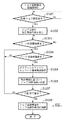
図6は、図4で説明したジョブ追跡印刷の全体処理の流れについて説明したフローチャートである。
(Job tracking print processing example)
FIG. 6 is a flowchart illustrating the overall processing flow of job tracking printing described in FIG.
アプリケーションから印刷処理が開始された後、ステップS610でプリンタドライバ203内のスプールシステム300は、グラフィックエンジン202からの描画命令(本実施形態では、DDI関数)をディスパッチャ301によってスプーラ302へ送信し、スプールファイル303としてページ単位に蓄積する。本実施例においてスプールファイル303に蓄積されるデータ形式は、描画命令から変換される中間コードデータ形式であるが、描画命令をそのまま格納してもよい。よって、スプールファイル303に蓄積されているデータは、描画命令と表記する。その後ステップS611で、スプールファイル303から描画命令を読み込む。
After the printing process is started from the application, in step S610, the spool system 300 in the
ステップS612では、スプールシステム内のデスプーラ305は、ジョブ追跡機能UI制御部401から図5A及び図5Bで説明したようにジョブの追跡を行う設定がなされている場合には、スプールファイルマネージャ304からの指令に基づきジョブ追跡用情報を収集し、グラフィックエンジン202に対する設定情報の生成を行い、グラフィックエンジン202に対して、生成した設定情報を設定し、スプールファイル303から読み出した描画命令を出力する。グラフィックエンジン202は、設定情報に基づいて、ジョブ追跡機能部400内のジョブ追跡機能処理部402を経由してジョブ追跡管理部500へと転送を行う(これがプロセスMに相当する)。
In step S612, when the
より詳しくは、例えば、ジョブ追跡を行うことが設定されている場合に、デスプーラ305は、描画命令が印刷開始命令であればジョブに関する属性情報や印刷が行われている環境情報などを追跡用データとし、ページ開始命令であればそのページに関する属性情報等を追跡用データとする。更にジョブ追跡機能UI制御部401に対してテキスト情報の抽出が指示されているのであれば、デスプーラ305は、テキスト描画コマンドから文字列情報など抽出し追跡用データとし、同じくイメージ抽出が指示されているのであれば、デスプーラ305は、各描画命令を確保してあるメモリ領域等にビットマップイメージとして描く指示等、描画命令及びジョブ追跡機能部400に指示された各種設定に依存した処理を実行することで、追跡用データの収集・生成を行い、これをジョブ追跡管理部500へと転送する。
More specifically, for example, when it is set to perform job tracking, the
ここで、追跡用データの生成処理ではなく、プリンタへ出力する印刷ジョブの生成処理では、デスプーラ305は、スプール時にプリンタドライバUI(UI制御部203B)からの印刷設定に基づいて作成したDEVMODE(印刷設定構造体)からCreateDC()したものを用いてグラフィックエンジン202へ出力する。一方、イメージ抽出が指示されている場合、つまり、追跡用データのうち追跡用ビットマップの生成処理の場合には、デスプーラ305は、ジョブ追跡機能UI制御部401を介して図5Bで設定された情報から、グラフィックエンジン202に対して設定する設定情報を生成する。
Here, in the generation process of the print job to be output to the printer instead of the generation process of the tracking data, the
具体的な手順としては、デスプーラ305は、CreateCompatibleDC()を生成し、グラフィックエンジン202に対して、ビット数カラー526、ビット数白黒527、解像度528で設定されている値に基づいて描画命令からビットマップの作成をCreateDIBSection()を発行することで依頼し、生成されたビットマップをSelectObject()でCreateCompatibleDC()に対応付ける。そして、グラフィックエンジン202が生成したビットマップを、ジョブ追跡機能処理部402が受け取るために、デスプーラ305は、グラフィックエンジン202が生成したビットマップのポインタをジョブ追跡機能処理部402に通知する。
As a specific procedure, the
なお、一般に、CreateDC()は、グラフィックエンジン202が描画した描画命令を出力先のプリンタオブジェクト(プリンタドライバ)へ出力するために用いられ、CreateCompatibleDC()は、確保したメモリ上へビットマップデータを書き込むために用いられる関数である。
In general, CreateDC () is used to output a drawing command drawn by the
続くステップS613では、1物理ページ分のジョブ追跡情報生成、転送処理が終了したかを判定し、終了していなければステップS611に戻る。 In subsequent step S613, it is determined whether the job tracking information generation and transfer processing for one physical page is completed. If not completed, the process returns to step S611.
一方、ステップS613で1物理ページ分の描画処理が終了していれば、ステップS614へ進んで、デスプーラ305は、スプールファイル303から追跡用データを生成したページの描画命令を再度読み込む。そして続くステップS615において、デスプーラ305がスプールファイルマネージャ304の指示により印刷データ用の生成(GDI関数への変換)を行い、グラフィックエンジン202へ出力し、グラフィックエンジン202で変換された描画命令(印刷用のDDI関数)をディスパッチャ301が受け取り、描画処理部203Cでページ記述言語の印刷データを生成してシステムスプーラ204へ書き出され、プリンタ1500への転送が行われる(これがプロセスPに相当する)。
On the other hand, if the drawing process for one physical page has been completed in step S613, the process proceeds to step S614, and the
ステップS616では、1物理ページ分の印刷処理が終了したかを判定し、終了していなければステップS611に戻り、終了していればステップS617へ進む。 In step S616, it is determined whether the printing process for one physical page is completed. If not completed, the process returns to step S611, and if completed, the process proceeds to step S617.
そして、ステップS617において、印刷ジョブが終了していれば処理を終え、終了していなければステップS611へ戻り当該ジョブに対する処理を続行する。 If it is determined in step S617 that the print job has been completed, the process ends. If not, the process returns to step S611 to continue the process for the job.
なお、図6のフローチャートでは、追跡用データの1ページを生成後、印刷データの1ページの生成処理を行っているが、本発明はこの順番に限るものではなく、印刷データの1ページの生成後、追跡用データの1ページの生成処理を行うよう構成してもよい。前者の手順だと、必ず追跡用データの生成が終わったものから印刷することで追跡が保証され、また、後者の手順だと、1ページ目の印刷処理の開始が早くなるという効果が得られる。いずれの場合でも、各ページ内で、追跡用データの生成と印刷データの生成とが交互に生成処理されることが望ましい。 In the flowchart of FIG. 6, after one page of tracking data is generated, one page of print data is generated. However, the present invention is not limited to this order, and one page of print data is generated. Thereafter, it may be configured to perform generation processing of one page of the tracking data. In the former procedure, the tracking is guaranteed by printing from the end of the generation of the tracking data, and in the latter procedure, the printing process for the first page can be started earlier. . In any case, it is desirable that generation of tracking data and generation of print data are alternately generated in each page.
(スプールシステム300の処理例)
次に、図6で説明したジョブ追跡印刷処理におけるスプールシステム300の処理について、図7から図10を用いて説明する。
(Processing example of spool system 300)
Next, processing of the spool system 300 in the job tracking print processing described with reference to FIG. 6 will be described with reference to FIGS.
先に示したとおり、デスプーラ305はジョブ追跡機能部400およびディスパッチャ301の2つの出力先にデータを出力する。本実施形態では図7に示したとおり、デスプーラ305に対する2つのプロセスMとPを生成し、スプールファイルマネージャ304がこれら2つのデスプーラプロセスMとPを制御する形式をとっている。ここで、第1のプロセスMはジョブ追跡機能部に対する出力に利用され、第2のプロセスPはプリンタ1500への印刷に利用される。両デスプールプロセスMとPの生成は、スプールファイルマネージャ304によって行われる。
As described above, the
以降、図8から図10において、スプールファイルシステム300内の処理について詳細に説明する。尚、各処理間の関連をそれぞれのステップで示したが、本実施形態の特徴としてデスプーラ305の2つのプロセスMとPは同様なので、図10に共通のフローチャートを示し、プロセスMのステップは最後にMを/プロセスPのステップは最後にPを添えて示した。
Hereinafter, the processing in the spool file system 300 will be described in detail with reference to FIGS. In addition, although the relationship between each process was shown by each step, since the two processes M and P of the
(スプーラ302の処理例)
図8は、スプーラ302における、スプールファイル303の生成におけるページ単位保存ステップの処理をフローチャートで示したものである。
(Processing example of spooler 302)
FIG. 8 is a flowchart showing the process of the page unit storage step in the generation of the
まずステップS801では、スプーラ302は、アプリケーションからグラフィックエンジン202を介して印刷要求を受け付ける。アプリケーションにおいては、プリンタドライバ203内のUI制御部203Bによって各種印刷設定項目が設定可能となる。印刷設定の一例としては、1物理ページに複数の論理ページを配置するといった、スプールシステム300を利用して実現するような項目等を含んでいる。
First, in step S801, the
ステップS802では、スプーラ302は、受け付けた印刷要求がジョブ開始要求か判定し、もしステップ802でジョブ開始要求であると判断した場合には、ステップS803に進み、スプーラ302は、中間データを一時的に保存するためのスプールファイル303を作成する。続いて、ステップS804では、スプーラ302は、スプールファイルマネージャ304へ印刷処理の進捗を通知し、続くステップS805でスプーラ302のページ数カウンタを1に初期化する。ここで、スプールファイルマネージャ304においては、印刷が開始されたジョブに対するジョブの情報や加工設定などをスプールファイル303より読み込み、記憶する。
In step S802, the
ステップS802においてジョブ開始要求ではなかったと判断した場合には、ステップS806に進む。ステップS806では、スプーラ302は、受け付けた要求がジョブ終了要求かどうかの判別を行う。ジョブ終了要求でないと判断した場合には、ステップS807に進み、改ページかどうかの判別を行う。もしもステップS807で改ページであると判断した場合には、ステップS808に進み、スプールファイルマネージャ304へ印刷処理の進捗を通知する。そしてページ数カウンタをインクリメントして、中間コードを格納しているページ描画ファイルを閉じ、次のページ描画ファイルを生成する。
If it is determined in step S802 that the request is not a job start request, the process advances to step S806. In step S806, the
ステップS807において、受け付けた印刷要求が改ページではないと判断した場合には、ステップS809に進み、スプーラ302は、ページ描画ファイルへの中間コードの書き出しの準備を行う。次に、ステップS810では、印字要求をスプールファイル303へ格納するため、スプーラ302は、印字要求のDDI関数の中間コードへの変換処理を行う。ステップS811では、スプーラ302は、ステップS810において格納可能な形に変換された印刷要求(中間コード)をスプールファイル303へ書き込む。
If it is determined in step S807 that the received print request is not a page break, the process advances to step S809, and the
その後、ステップ501に戻り、再びアプリケーションからの印刷要求を受け付ける。この一連のステップS801からステップS811までの処理を、アプリケーションよりジョブ終了要求を受け取るまで続ける。また、スプーラ302は、同時にプリンタドライバ203から加工設定等の情報を取得し、スプールファイル303に格納する。
Thereafter, the process returns to step 501 to accept a print request from the application again. The series of processing from step S801 to step S811 is continued until a job end request is received from the application. The
ステップS806にて、アプリケーションからの印刷要求がジョブ終了であると判断した場合には、アプリケーションからの印刷要求は全て終了であるので、ステップS812に進み、スプールファイルをクローズするとともにスプールファイルマネージャ304へ印刷処理の進捗を通知し、処理を終える。
If it is determined in step S806 that the print request from the application is the end of the job, all print requests from the application are complete, so the process proceeds to step S812 to close the spool file and to the
(スプールファイルマネージャ304の処理例)
図9は、スプールファイルマネージャ304における、スプールファイル303生成プロセスと以降説明するジョブ追跡情報生成プロセスおよび印刷データ生成プロセスの間での制御の詳細をフローチャートで示したものである。ここで、上記のようにデスプーラ305からの通知で、プロセスMからのものはステップの最後にMを付けて、プロセスPからのものはステップの最後にPを付けて示している。
(Processing example of spool file manager 304)
FIG. 9 is a flowchart showing details of control in the
ステップS901では、スプールファイルマネージャ304は、スプーラ302からの進捗通知、あるいはデスプーラ305からの印刷処理またはジョブ追跡生成処理に関する進捗通知を受け付ける。
In step S <b> 901, the
ステップS902では、スプールファイルマネージャ304は、もし進捗通知が前述のステップS804において通知されるスプーラ302からの印刷開始通知であるかどうか判定し、もしそうであればステップS903へ進み、印刷の加工設定をスプールファイル303から読み込み、ジョブの管理を開始する。
In step S902, the
一方、ステップS902において、スプーラ302からの印刷開始通知でなければステップS904へ進み、スプールファイルマネージャ304は、進捗通知が前述のステップS808において通知されるスプーラ302からの1論理ページの印刷終了通知、すなわち論理ページの改ページ処理であるかどうか判定する。ここで1論理ページの印刷終了通知であればステップS905へ進み、この論理ページに対する論理ページ情報を格納し、ステップS906へ進む。
On the other hand, if the print start notification is not received from the
ステップS906では、この時点でスプールが終了したn論理ページに対して、1物理ページの描画処理が開始できるかを判定する。ここで、描画処理可能である場合はステップS907へ進み、印刷する1物理ページに対して割り付けられる論理ページ数から物理ページ番号を決定する。物理ページの計算については、例えば、加工設定が1物理ページに4論理ページを配置するような設定の場合、第1物理ページは第4論理ページがスプールされた時点で印刷可能となり、第1物理ページとなる。続いて、第2物理ページは第8論理ページがスプールされた時点で印刷可能となる。また、論理ページ数の総数が1物理ページに配置する論理ページ数の倍数でなくても、ステップS812におけるスプール終了通知によって1物理ページに配置する論理ページが決定可能である。一方、ステップS906で描画処理が不可能である場合はステップS901に戻り、次の通知を待つ。 In step S906, it is determined whether drawing processing of one physical page can be started with respect to the n logical pages that have been spooled at this time. If drawing processing is possible, the process advances to step S907 to determine a physical page number from the number of logical pages allocated to one physical page to be printed. Regarding the calculation of the physical page, for example, when the processing setting is such that four logical pages are arranged in one physical page, the first physical page can be printed when the fourth logical page is spooled, and the first physical page is printed. It becomes a page. Subsequently, the second physical page can be printed when the eighth logical page is spooled. Even if the total number of logical pages is not a multiple of the number of logical pages allocated to one physical page, the logical page to be allocated to one physical page can be determined by the spool end notification in step S812. On the other hand, if the drawing process is impossible in step S906, the process returns to step S901 to wait for the next notification.
ステップS908では、描画処理可能となった物理ページを構成する論理ページ番号と、その物理ページ番号などの情報がスプールファイル303に格納される。そして、続くステップS909では、格納された物理ページ情報とともにジョブ追跡用に生成されたデスプーラのプロセスに対して描画要求通知を行う。なお、第一物理ページに対する描画処理要求を行う時点では、デスプーラ305のプロセス生成がなされていないので、ジョブ追跡用プロセス、印刷用プロセスをこのステップで生成したあと、要求の通知が行われることとなる。
In
その後ステップS901に戻り、次の通知を待つ。本実施形態においては、印刷データ1ページ、即ち1物理ページを構成する論理ページがスプールされた時点で印刷ジョブのスプールが全て終了していなくても印刷処理が可能である。 Thereafter, the process returns to step S901 to wait for the next notification. In the present embodiment, print processing can be performed even if all the print jobs are not spooled when one page of print data, that is, a logical page constituting one physical page is spooled.
本実施形態におけるデスプーラ305は印刷処理を行う単位として1物理ページ数を想定している。また、先述のステップS908では、1物理ページの印刷処理を行うのに必要な情報をファイルに逐次保存し、再利用可能な形式にしているが、再利用不要な場合には、共有メモリ等高速な媒体を使用し、1物理ページ単位で次々と上書きする実装にして、速度とリソースを節約するような実装形式であってもよい。また、デスプールの進捗よりもスプールの進捗の方が早い場合や、全ページのスプール終了後からデスプールが開始されるような場合には、ステップS909で1物理ページ毎にページ印刷可能を通知せずに、デスプール側の進捗に応じて、複数物理ページもしくは全物理ページが印刷可能になったという通知内容にして、通知回数を節約することが可能である。
The
ステップS904で1論理ページの印刷終了通知と判定されなかった場合、ステップS910へ進む。ステップS910では、スプールファイルマネージャ304は、前述のステップS812において通知されるスプーラ302からのジョブ終了通知であるかどうかを判定する。ここで、ジョブ終了通知である場合、前述のステップS906へ進む。一方、ジョブ終了通知でない場合、ステップS911へ進む。
If it is not determined in step S904 that one logical page has been printed, the process proceeds to step S910. In step S910, the
ステップS911では、スプールファイルマネージャ304は、受け付けた通知がデスプーラ305における印刷用プロセスからの1物理ページの印刷終了通知であるかどうか判定する。ここで、1物理ページの印刷終了通知である場合はステップS912へ進む。そうでなければステップS915へ進む。
In step S911, the
ステップS912では、デスプーラ305における印刷用プロセスから1物理ページの印刷終了通知を受けたので、次に加工設定の印刷が全て終了したかを判定する。印刷終了したと判断された場合、ステップS913へ進み、デスプーラ305におけるジョブ追跡用プロセスに対して追跡情報生成処理に対する終了通知を行う。続いてステップS914へ進み、デスプーラ305における印刷用プロセスに対して印刷終了の通知を行う。一方、加工設定に対する印刷がまだ終了していないと判断した場合、前述のステップS906へ進む。
In step S912, since the printing end notification of one physical page is received from the printing process in the
ステップS911で1物理ページの印刷終了通知でなければ、ステップS915へ進む。ステップS915では、スプールファイルマネージャ304は、受け付けた通知がデスプーラ305におけるジョブ追跡用プロセスからの1物理ページの描画処理終了通知であるかどうかを判定する。ここで、1物理ページの描画処理終了通知である場合は対応する物理ページに対する印刷処理を行ってよいので、ステップS916へ進み、デスプーラ305における印刷用プロセスに対して対応する物理ページの印刷要求を行う。このように、ジョブ追跡に利用する描画処理が完了してから実際の印刷プロセスを実行することにより、ジョブ追跡システムの信頼性を高めることが可能となっている。
If it is not a print end notification of one physical page in step S911, the process proceeds to step S915. In step S <b> 915, the
一方、ステップS915において、1物理ページの描画処理終了通知でない場合は、ステップS917へ進む。ステップS917では、スプールファイルマネージャ304は、受け付けた通知がデスプーラ305からの印刷終了通知かどうかを判定する。ここで、通知がデスプーラ305からの印刷終了通知と判定された場合、ステップS918へ進み、スプールファイルマネージャ304は、スプールファイル303の該当するページ描画ファイルの削除を行い処理を終える。
On the other hand, in step S915, if it is not a notice of completion of drawing processing for one physical page, the process proceeds to step S917. In step S 917, the
一方、デスプーラ305からの印刷終了通知でなかった場合はステップS919へ進み、その他通常処理またはエラー処理などを行い、次の通知を待つ。
On the other hand, if the print end notification is not received from the
(デスプーラ305の処理例)
図10は、デスプーラ305における、描画データの生成プロセスの詳細をフローチャートで示したものである。デスプーラ305は、スプールファイルマネージャ304からの印刷要求に応じて、スプールファイル303から必要な情報を読み出して描画データを生成する。生成された描画データにおけるプリンタへの転送方法については図4および図6で説明した通りである。
(Processing example of despooler 305)
FIG. 10 is a flowchart showing details of the drawing data generation process in the
また、図7および図9で説明したとおり、デスプーラ305はジョブ追跡情報出力用および印刷データ出力用の2つの目的で利用されるが、描画方法については出力先が異なることと、追跡用データ(イメージ抽出時)と印刷データとでグラフィックエンジン202が生成するデータのサイズ、圧縮方法などが異なっている。しかし、印刷される描画内容と追跡用データで保持されている描画内容は、なんら違いはない。このことにより、追跡データが実際の印刷と同じ処理系で行われることによる追跡データの信頼性向上が実現可能となる。以降、プロセスMとPに共通のデスプーラ305の処理の流れを説明する。
As described with reference to FIGS. 7 and 9, the
まず、ステップS1001において、前述のスプールファイルマネージャ304からの通知を入力する。続くステップS1002では、デスプーラ305は、入力された通知がジョブの終了通知かどうか判定し、ジョブ終了通知であるならばステップS1003へ進み、終了フラグを立て、ステップS1005へ進む。
First, in step S1001, a notification from the
一方、ステップS1002においてジョブ終了通知でない場合は、ステップS1004に進み、前述のステップS909あるいはステップS916における1物理ページの描画開始要求が通知されたかどうか判定する。ステップS1004において1物理ページの描画開始要求と判定されなかった場合は、ステップS1010へ進み、その他エラー処理を行い、ステップS1001へ戻り次の通知を待つ。 On the other hand, if it is not a job end notification in step S1002, the process proceeds to step S1004, and it is determined whether a drawing start request for one physical page in step S909 or step S916 is notified. If it is not determined as a drawing start request for one physical page in step S1004, the process proceeds to step S1010 to perform other error processing, and returns to step S1001 to wait for the next notification.
一方、ステップS1004において1物理ページの印刷開始要求と判定された場合はステップS1005へ進み、デスプーラ305は、ステップS1005で通知を受けた印刷処理可能な物理ページ情報を例えばRAM2などに保存しておく。続くステップS1006では、デスプーラ305は、ステップS1005で保存された物理ページのすべてに関して印刷処理が済んでいるかどうか判定する。ここで全物理ページの印刷処理が済んでいる場合は、ステップS1007へ進み、前述のステップS1003で終了フラグが立てられているのか判定する。終了フラグがたっている場合は、ジョブの印刷が終了したとみなし、デスプーラ305の処理終了の通知をスプールファイルマネージャ304に通知し、処理を終える。ステップS1007で終了フラグが立っていないと判定された場合は、ステップS1001へ戻り次の通知を待つ。
On the other hand, if it is determined in step S1004 that it is a request to start printing one physical page, the process proceeds to step S1005, and the
一方、ステップS1006で、印刷可能な物理ページが残っていると判定された場合には、ステップS1008へ進み、デスプーラ305は、保存された物理ページ情報から未処理の物理ページ情報を順に読み出し、描画データ生成に必要な情報を読み込み、処理を行う。
On the other hand, if it is determined in step S1006 that a printable physical page remains, the process advances to step S1008, and the
図4において説明したとおり、デスプーラ305における描画処理は、スプールファイル303に格納された描画要求命令をグラフィックエンジン202が認識可能な形式(GDI関数)に変換し、転送する。例えば、複数論理ページを1物理ページにレイアウトするような加工設定については、このステップで縮小配置を考慮にいれながら変換する。また、具体的には、図10の処理の場合も、図6の処理で説明したように、デスプーラ305は、グラフィックエンジン202に対して、処理目的により異なる設定情報(CreateDC():印刷処理時、CreateCompatibleDC():追跡用データ生成時)をAPIで設定している。
As described with reference to FIG. 4, in the drawing process in the
必要な印刷処理が終えたならば、続くステップS1009において1物理ページの印刷データ生成終了の通知をスプールファイルマネージャ304に対して行う。そして、再びステップS1006へ戻り、ステップS1005に保存されている描画処理開始可能な物理ページについての描画処理を順次繰り返す。
When the necessary print processing is completed, in step S1009, the
<デスプーラ305とジョブ追跡機能処理部402との通信例>
図11は、デスプーラ305とジョブ追跡機能処理部402との通信について説明した図である。尚、デスプーラ305の制御はスプールファイルマネージャ304が行なっており、要求通知の発行はスプールファイルマネージャ304に指示され、要求応答はスプールファイルマネージャ304に伝達される。
<Communication Example between
FIG. 11 is a diagram illustrating communication between the
デスプーラ305からは、図10において説明した描画要求に対応した要求がジョブ追跡機能処理部402に送付される。デスプーラ305は、ジョブ追跡機能処理部402から、各要求に対する処理が正常に終了したことを通知された上で、スプールファイルマネージャ304に進捗の通知を行うこととなる。
From the
図中の(1)については、図9におけるステップS909において、第一物理ページに対する描画処理開始時にプロセス生成される、(2)ないし(4)については、物理ページ数分繰り返される処理で、ステップS909およびステップS915の通知処理が該当する。そして、(5)については、ステップS913において実施される処理に該当する。 (1) in the figure is a process generated at the start of the drawing process for the first physical page in step S909 in FIG. 9, and (2) to (4) are processes repeated for the number of physical pages. The notification process of S909 and step S915 corresponds. And (5) corresponds to the process performed in step S913.
(ジョブ追跡機能処理部402の処理例)
図12は、ジョブ追跡機能処理部402の処理例の概略を示すフローチャートである。
(Processing example of job tracking function processing unit 402)
FIG. 12 is a flowchart illustrating an outline of a processing example of the job tracking
ステップS1201で、図11の(1)に示したように、デスプーラ305を介したスプールファイルマネージャ304からの印刷ジョブ開始要求を待ち、印刷ジョブ開始要求があるとステップS1202で、図5Bの設定画面から設定され図2Bのジョブ追跡設定情報2dに記憶されたジョブ追跡の設定情報を読み出す。
In step S1201, as shown in (1) of FIG. 11, a print job start request from the
ステップS1203では、図11の(2)で示したページ印刷開始要求を待って、ページ印刷開始要求があるとステップS1204に進んで、各ページのページ描画処理要求を待つ。ベージ描画処理要求があるとステップS1205に進んで、デスプーラ305によりスプールファイル303から読み出されてグラフィックエンジン202に送られた中間コードデータから、グラフィックエンジン202によりプリンタ1500に送られるデータと同様に展開されたビットマップデータを含むページ描画情報を取得する。次に、ステップS1206では、ステップS1202で読み出したジョブ追跡設定情報に従ってページ描画情報から追跡管理のための情報を作成する。ステップS1207では、図11の(5)で示した印刷終了要求をデスプーラ305から受信したか否かを判断し、受信が無ければステップS1204に戻って、次のページについてのジョブ追跡情報を作成する。
In step S1203, the page print start request shown in (2) of FIG. 11 is waited. If there is a page print start request, the process proceeds to step S1204 to wait for a page drawing process request for each page. If there is a page drawing processing request, the process advances to step S1205, and the intermediate code data read from the
印刷終了要求を受信すると、ステップS1208に進んで作成されたジョブ追跡情報(図2Bではジョブ追跡作成データ)をジョブ追跡管理部500に渡す。ジョブ追跡情報を渡されたジョブ追跡管理部500の処理は、図13により次に説明する。
When the print end request is received, the process proceeds to step S1208, and the created job tracking information (job tracking creation data in FIG. 2B) is passed to the job tracking
尚、図12に図示のフローによって、1つのプリントジョブのジョブ追跡情報が作成されジョブ追跡管理部500に渡されるが、実際の動作では連続して複数のプリントジョブが実行される場合もあり、その場合には、図12に図示のフローを繰り返して、プリントジョブ単位にジョブ追跡管理部500に渡されてもよいし、一連の複数のプリントジョブが終了した後にジョブ追跡管理部500に渡されてもよい。その場合には、ステップS1207とS1208との間に、一連の複数のプリントジョブの終了通知を待つことになる。
Note that, according to the flow shown in FIG. 12, job tracking information of one print job is created and passed to the job tracking
(ジョブ追跡管理部500の処理例)
図13は、ジョブ追跡管理部500の処理例の概略を示すフローチャートである。尚、ジョブ追跡の管理処理については、既存の処理が適用可能であり詳説はしない。
(Processing example of job tracking management unit 500)
FIG. 13 is a flowchart illustrating an outline of a processing example of the job tracking
まず、ステップS1301とS1304において、ジョブ追跡機能処理部402からのジョブ追跡情報の格納要求か、蓄積されたジョブ追跡情報に基づくジョブ追跡の管理処理(検索、照合など)の要求かを判断する。
First, in steps S1301 and S1304, it is determined whether the job tracking information storage request from the job tracking
ジョブ追跡情報の送信の場合は、ステップS1302に進んでジョブ追跡機能処理部402からジョブ追跡情報を受信し、ステップS1303で追跡情報格納サーバ1000のジョブ単位に追跡可能に格納する。一方、ジョブ追跡の管理処理の要求であれば、ステップS1305進んで図5Bで設定された管理クライアント名や識別名に従ってジョブ単位に追跡情報格納サーバ1000のジョブ追跡情報を参照し、ステップS1306でジョブ追跡の結果を出力する。
In the case of transmission of the job tracking information, the process proceeds to step S1302, and the job tracking information is received from the job tracking
尚、ジョブ追跡の管理処理は、ジョブ追跡管理部500がホストコンピュータ3000に有る場合は、アプリケーション201を介し、あるいはUIから直接ジョブ追跡管理部500に指示されてもよいし、プリンタドライバ203のUI制御部203Bやジョブ追跡機能UIブ401を介して指示されてもよい。又、ホストコンピュータ3000とは別に管理クライアント4000となる追跡管理コンピュータが有る場合は、ネットワークを介しで指示されることになる。
The job tracking management process may be instructed to the job tracking
[第2の実施形態]
前述の実施形態では、図7に示したとおり、デスプーラ305に対する2つのプロセスMとPを生成し、スプールファイルマネージャ304がこれら2つのデスプーラプロセスMとPを制御する形式をとっていたが、デスプーラ305内で2つのプロセスMとPを制御する形式をとってもよい。この場合も、図9および図10の処理の流れを若干変更することで実現可能であるので、図12および図13を用いて変更点を説明する。
[Second Embodiment]
In the above-described embodiment, as shown in FIG. 7, two processes M and P for the
図14および図15は、それぞれスプールファイルマネージャ304における図9からの変更部分を反映した図、デスプーラ305における図10からの変更部分を反映した図である。
FIG. 14 and FIG. 15 are diagrams reflecting the changed portion from FIG. 9 in the
まず、図14では、図9におけるステップS915およびステップS916の処理がデスプーラ305側に移動している。同処理は、図10におけるステップS1008に移動し、図15のおけるステップS1508−1 およびステップS1508−2として行われることとなる。
First, in FIG. 14, the processes in steps S <b> 915 and S <b> 916 in FIG. 9 are moved to the
次に、図9におけるステップS909は、特にジョブ追跡用デスプールプロセスを意識せず、単にデスプーラ305への要求(ステップS1409)に変わる。また、ステップS913とステップS914についても、個別に通知を行う必要がなくなり、単にデスプーラ305への通知(ステップS1413)となる。 Next, step S909 in FIG. 9 is changed to a request to the despooler 305 (step S1409) without being particularly conscious of the job tracking despooling process. In addition, it is not necessary to individually notify step S913 and step S914, and the notification is simply sent to the despooler 305 (step S1413).
また、本実施形態では、図6におけるステップS615では、デスプーラ305がスプールファイルマネージャ304の指示ではなく、自身の処理において印刷データの生成、転送を行うことになる。
Further, in the present embodiment, in step S615 in FIG. 6, the
[種々のシステム構成の実施形態例]
図16A乃至図16Eは、本発明の様々なシステムでの運用形態を説明するための図である。
[Examples of Embodiments of Various System Configurations]
FIG. 16A to FIG. 16E are diagrams for explaining operation modes in various systems of the present invention.
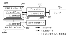
図16Aは、本発明の最もシンプルな運用例を示す図である。ホストコンピュータ3000内にジョブ追跡管理部500を配し、印刷データはプリンタドライバ203からプリンタ1500へ直接転送され、追跡用データはジョブ追跡機能部400からホストコンピュータ3000内のジョブ追跡機能管理部500を介して追跡情報管理サーバ1000へと送られる。本構成は本発明を実施するための最小構成であり、第一の実施形態では本構成を用いた形態についての説明を行った。
FIG. 16A is a diagram showing the simplest operation example of the present invention. A job
図16Bは、図16Aに対し、ジョブ追跡管理部500をホストコンピュータ3000とは別の追跡管理コンピュータ6000に配したものでる。印刷データは図16Aと同じく、プリンタドライバ203から直接プリンタ1500へ転送され、追跡用データはジョブ追跡機能部400から追跡管理コンピュータ6000内のジョブ追跡機能管理部500を介して追跡情報管理サーバ1000へと送られる。本構成を採ることで追跡用データの追跡情報管理サーバ1000を、例えばネットワーク負荷が軽くなる日や時間帯にスケジューリングすることが可能となり、追跡情報管理サーバ1000への負荷を制御することが可能になる。
FIG. 16B is a diagram in which the job tracking
図16Cは、図16Aに対し、プリントサーバ7000をホストコンピュータ3000とプリンタ1500の間に入れたものである。印刷データはプリンタドライバ203からプリントサーバ7000の該当するプリンタキュー(プリントスプーラ)を通ってプリンタ1500へ転送され、追跡用データは図16Aと同じく、ジョブ追跡機能部400からホストコンピュータ3000内のジョブ追跡機能管理部500を介して追跡情報管理サーバ1000へと送られる。本構成を採ることで、プリントサーバ7000を用いる運用形態にも適応されることが出来ると共に、プリントサーバ7000内にプリンタドライバ203を置くことで、ホストコンピュータ3000へのプリンタドライバの配布や同期、設定情報の共有化などが可能となる。更には、ジョブ追跡機能に係わる各種設定をプリントサーバ7000上で一括管理することも可能となり、ジョブ追跡機能の各種設定を実行する権限の無いユーザが設定変更行えなくなるような機構も併せ持つこととなる。
FIG. 16C is a diagram in which a
図16Dは、図16Bと図16Cの構成を併用したものであり、プリントサーバ7000をホストコンピュータ3000とプリンタ1500の間に入れ、ジョブ追跡管理部500をホストコンピュータ3000とは別の追跡管理コンピュータ6000に配したものである。印刷データは図16Cと同じく、プリンタドライバ203からプリントサーバ7000の該当するプリンタキュー(プリントスプーラ)を通ってプリンタ1500へ転送され、追跡用データは図16Bと同じく、ジョブ追跡機能部400から追跡管理コンピュータ6000内のジョブ追跡機能管理部500を介して追跡情報管理サーバ1000へと送られる。本構成を採ることで、図16Bと図16Cの利点を併せ持つことが可能となる。
FIG. 16D is a combination of the configurations of FIGS. 16B and 16C. The
図16Eは、図16Dの追跡管理コンピュータ6000とプリントサーバ7000とを同一のコンピュータ上で実現するようにプリントサーバ兼追跡管理コンピュータ8000を設けたものである。印刷データはプリンタドライバ203からプリントサーバ兼追跡管理コンピュータ8000の該当するプリンタキュー(プリントスプーラ)を通ってプリンタ1500へ転送され、追跡用データはジョブ追跡機能部400からプリントサーバ兼追跡管理コンピュータ8000内のジョブ追跡機能管理部500を介して追跡情報管理サーバ1000へと送られる。本構成を採ることで図16Dでは追跡管理コンピュータ6000、プリントサーバ7000の2台のコンピュータであったが、これをプリントサーバ兼追跡管理コンピュータ8000の1台に集約することで、設置スペースやコストの削減を行うことが可能となる。
FIG. 16E shows a print server /
本発明は以上説明したような様々な形態に適用可能であり、図16Aおよび先の実施系において説明した最小構成だけでなく、導入形態に応じた柔軟なシステム構成が可能となる。 The present invention can be applied to various forms as described above, and enables not only the minimum structure described in FIG. 16A and the previous implementation system, but also a flexible system structure according to the introduction form.
なお、本発明は、複数の機器(例えばコンピュータ、インタフェース機器、リーダ、プリンタなど)から構成されるシステムに適用しても、一つの機器からなる装置(複写機、プリンタ、ファクシミリ装置など)に適用してもよい。 Note that the present invention can be applied to a system (copier, printer, facsimile machine, etc.) consisting of a single device even if it is applied to a system consisting of a plurality of devices (eg, computer, interface device, reader, printer, etc.). May be.
また、本発明の目的は、前述した実施形態で示したフローチャートの手順を実現するプログラムコードを記憶した記憶媒体を、システムあるいは装置のコンピュータ(またはCPUやMPU)が記憶媒体に格納されたプログラムコードを読出し実行することによっても達成される。 Another object of the present invention is to store a storage medium storing a program code for realizing the procedure of the flowchart shown in the above-described embodiment, and a program code stored in the storage medium by a computer (or CPU or MPU) of the system or apparatus. It is also achieved by reading and executing.
この場合、記憶媒体から読み出されたプログラムコード自体が前述した実施形態の機能を実現することになり、そのプログラムコードを記憶した記憶媒体は本発明を構成することになる。 In this case, the program code itself read from the storage medium realizes the functions of the above-described embodiments, and the storage medium storing the program code constitutes the present invention.
プログラムコードを供給するための記憶媒体としては、例えば、フロッピー(登録商標)ディスク、ハードディスク、光ディスク、光磁気ディスク、CD−ROM、CD−R、磁気テープ、不揮発性のメモリカード、ROMなどを用いることができる。 As a storage medium for supplying the program code, for example, a floppy (registered trademark) disk, hard disk, optical disk, magneto-optical disk, CD-ROM, CD-R, magnetic tape, nonvolatile memory card, ROM, or the like is used. be able to.
また、コンピュータが読み出したプログラムコードを実行することにより、前述した実施形態の機能が実現されるだけでなく、そのプログラムコードの指示に基づき、コンピュータ上で稼動しているOS(オペレーティングシステム)などが実際の処理の一部または全部を行い、その処理によって前述した実施形態の機能が実現される場合も含まれる。 Further, by executing the program code read by the computer, not only the functions of the above-described embodiments are realized, but also an OS (operating system) operating on the computer based on the instruction of the program code. A case where part or all of the actual processing is performed and the functions of the above-described embodiments are realized by the processing is also included.
更に、記憶媒体から読出されたプログラムコードが、コンピュータに挿入された機能拡張ボードやコンピュータに接続された機能拡張ユニットに備わるメモリに書き込まれた後、そのプログラムコードの指示に基づき、その機能拡張ボードや機能拡張ユニットに備わるCPUなどが実際の処理の一部または全部を行い、その処理によって前述した実施形態の機能が実現される場合も含まれる。 Further, after the program code read from the storage medium is written in a memory provided in a function expansion board inserted into the computer or a function expansion unit connected to the computer, the function expansion board is based on the instruction of the program code. Also included is a case where the CPU or the like provided in the function expansion unit performs part or all of the actual processing, and the functions of the above-described embodiments are realized by the processing.
Claims (22)
アプリケーションから出力される描画命令を格納する格納手段と、
前記格納手段から読み出される描画命令を用いて、印刷ジョブの各ページの印刷データの内容を識別可能とするページ単位の追跡用データの生成処理を実行する追跡用データ生成手段と、
前記格納手段から読み出される描画命令を用いて、ページ単位の印刷データの生成処理を実行する印刷データ生成手段と、
前記追跡用データ生成手段による前記ページ単位の追跡用データの生成処理と、前記印刷データ生成手段による前記ページ単位の印刷データの生成処理とが連続して実行されるべく制御する制御手段とを有することを特徴とする情報処理装置。 An information processing apparatus that generates a print job to be printed by a printing apparatus,
Storage means for storing drawing commands output from the application;
Tracking data generating means for executing processing for generating tracking data in units of pages that makes it possible to identify the contents of print data of each page of a print job , using a drawing command read from the storage means;
Print data generation means for executing print data generation processing in units of pages using a drawing command read from the storage means;
Wherein a generation process of chasing data in the page unit by the chasing data generation means, and control means for controlling to the print data generation processing of the page unit by the print data generation means is executed in succession An information processing apparatus characterized by that.
前記印刷データ生成手段は、前記格納手段から読み出される描画命令を前記グラフィックエンジン手段に出力し処理させることで、前記ページ単位の印刷データの生成処理を実行することを特徴とする請求項1乃至9のいずれか1項に記載の情報処理装置。 The tracking data generation means executes the generation processing of the tracking data for each page by causing the graphic engine means to output and process a drawing command read from the storage means,
10. The print data generation unit executes the print data generation process for each page by outputting a rendering command read from the storage unit to the graphic engine unit for processing. The information processing apparatus according to any one of the above.
アプリケーションから出力される描画命令を格納する格納手段から読み出される該描画命令を用いて、印刷ジョブの各ページの印刷データの内容を識別可能とするページ単位の追跡用データの生成処理を実行する追跡用データ生成工程と、
前記追跡用データ生成工程での前記ページ単位の追跡用データの生成処理と連続して実行され、前記格納手段から読み出される前記描画命令を用いて前記ページ単位の印刷データの生成処理を実行する印刷データ生成工程とを有することを特徴とする情報漏洩抑止方法。 An information leakage suppression method in an information processing apparatus for generating a print job to be printed by a printing apparatus,
Tracking that executes processing for generating tracking data for each page that makes it possible to identify the contents of the print data of each page of the print job by using the drawing command read from the storage unit that stores the drawing command output from the application Data generation process,
Printing that is executed in succession to the tracking data generation process for each page in the tracking data generation step, and that executes the print data generation process for each page using the drawing command read from the storage means And a data generation step.
前記印刷データ生成工程では、前記格納手段から読み出される描画命令を前記グラフィックエンジン手段に出力し処理させることで、前記ページ単位の印刷データの生成処理を実行することを特徴とする請求項11乃至19のいずれか1項に記載の情報漏洩抑止方法。 In the tracking data generation step, the drawing command read from the storage unit is output to the graphic engine unit to be processed, thereby executing the page-based tracking data generation process,
20. The print data generation step executes print data generation processing for each page by outputting a rendering command read from the storage unit to the graphic engine unit for processing. The information leakage prevention method according to any one of the above.
Priority Applications (4)
| Application Number | Priority Date | Filing Date | Title |
|---|---|---|---|
| JP2004339440A JP4164488B2 (en) | 2004-11-24 | 2004-11-24 | Information leakage prevention method, information processing apparatus and driver program for realizing the method |
| US11/283,145 US8451474B2 (en) | 2004-11-24 | 2005-11-18 | Method of protecting leakage of information, and information processing apparatus and driver program which implement the method |
| EP05257183.3A EP1662371B1 (en) | 2004-11-24 | 2005-11-22 | Method of protecting leakage of information, and information processing apparatus and driver program which implement the method |
| CNB2005101233508A CN100481100C (en) | 2004-11-24 | 2005-11-23 | Method of protecting leakage of information, and information processing apparatus implementing the method |
Applications Claiming Priority (1)
| Application Number | Priority Date | Filing Date | Title |
|---|---|---|---|
| JP2004339440A JP4164488B2 (en) | 2004-11-24 | 2004-11-24 | Information leakage prevention method, information processing apparatus and driver program for realizing the method |
Publications (3)
| Publication Number | Publication Date |
|---|---|
| JP2006146814A JP2006146814A (en) | 2006-06-08 |
| JP2006146814A5 JP2006146814A5 (en) | 2007-01-25 |
| JP4164488B2 true JP4164488B2 (en) | 2008-10-15 |
Family
ID=36011177
Family Applications (1)
| Application Number | Title | Priority Date | Filing Date |
|---|---|---|---|
| JP2004339440A Expired - Fee Related JP4164488B2 (en) | 2004-11-24 | 2004-11-24 | Information leakage prevention method, information processing apparatus and driver program for realizing the method |
Country Status (4)
| Country | Link |
|---|---|
| US (1) | US8451474B2 (en) |
| EP (1) | EP1662371B1 (en) |
| JP (1) | JP4164488B2 (en) |
| CN (1) | CN100481100C (en) |
Families Citing this family (9)
| Publication number | Priority date | Publication date | Assignee | Title |
|---|---|---|---|---|
| JP4574525B2 (en) * | 2005-11-28 | 2010-11-04 | キヤノン株式会社 | Printing system, program, information collection method, and information retrieval method |
| JP2007172505A (en) * | 2005-12-26 | 2007-07-05 | Konica Minolta Business Technologies Inc | Image forming apparatus, image forming method and program |
| US20080080002A1 (en) * | 2006-09-21 | 2008-04-03 | Wills Cheyenne C | Method and Apparatus for Performing Print Spooling Within a Computer System |
| US8164767B2 (en) * | 2007-01-26 | 2012-04-24 | Ricoh Company, Ltd. | Print driver with processed print data management capability |
| CN104268479B (en) * | 2014-09-29 | 2017-03-01 | 北京奇虎科技有限公司 | A kind of method of text maninulation isolation, device and mobile terminal |
| US9880792B2 (en) * | 2015-03-20 | 2018-01-30 | Ricoh Company, Ltd. | Management system, information processing device, and management method |
| CN106886377A (en) * | 2015-12-15 | 2017-06-23 | 北京京航计算通讯研究所 | Concerning security matters carrier Life cycle print control program and console |
| CN107908332A (en) * | 2017-11-23 | 2018-04-13 | 东软集团股份有限公司 | One kind applies interior text clone method, reproducing unit, storage medium and electronic equipment |
| JP2020006606A (en) * | 2018-07-10 | 2020-01-16 | シャープ株式会社 | Job-related notification output device, compound machine, image formation device and job-related notification output method |
Family Cites Families (36)
| Publication number | Priority date | Publication date | Assignee | Title |
|---|---|---|---|---|
| US5299026A (en) * | 1991-11-12 | 1994-03-29 | Xerox Corporation | Tracking the reproduction of documents on a reprographic device |
| JPH10161823A (en) * | 1996-11-27 | 1998-06-19 | Nec Corp | Print system |
| JP3003637B2 (en) | 1997-07-31 | 2000-01-31 | 日本電気株式会社 | Printing equipment |
| JP4035232B2 (en) | 1998-05-21 | 2008-01-16 | キヤノン株式会社 | Image forming apparatus and control method thereof |
| US6313920B1 (en) * | 1998-08-17 | 2001-11-06 | Microsoft Corporation | System and method for remote printing using incremental font subsetting |
| JP2000242463A (en) | 1999-02-24 | 2000-09-08 | Nec Corp | Printing system |
| JP2001005629A (en) | 1999-06-25 | 2001-01-12 | Ricoh Co Ltd | Network system, method for managing printer, and recording medium |
| US6825943B1 (en) * | 1999-11-12 | 2004-11-30 | T/R Systems | Method and apparatus to permit efficient multiple parallel image processing of large jobs |
| JP4387553B2 (en) | 2000-04-27 | 2009-12-16 | キヤノン株式会社 | Printing control apparatus and method and information processing apparatus and method |
| JP2002149371A (en) | 2000-11-13 | 2002-05-24 | Ricoh Co Ltd | Security management system by print log and print data storage |
| US7010593B2 (en) * | 2001-04-30 | 2006-03-07 | Hewlett-Packard Development Company, L.P. | Dynamic generation of context-sensitive data and instructions for troubleshooting problem events in a computing environment |
| JP2003011441A (en) | 2001-06-27 | 2003-01-15 | Kyocera Corp | Imaging apparatus |
| JP4817556B2 (en) * | 2001-09-14 | 2011-11-16 | キヤノン株式会社 | Information processing apparatus, document processing method and program in information processing apparatus |
| US6666594B2 (en) * | 2001-10-19 | 2003-12-23 | Hewlett-Packard Development Company, L.P. | Method and system for web based printer error information |
| JP2003211740A (en) * | 2002-01-17 | 2003-07-29 | Fuji Xerox Co Ltd | Printing controller, printing control method and printer |
| ATE317333T1 (en) | 2002-03-08 | 2006-02-15 | Seiko Epson Corp | PRINTING SYSTEM FOR GENERATING MULTICHROMATIC PRINT DATA FROM MONOCHROMATIC PRINT DATA |
| JP3835322B2 (en) * | 2002-03-22 | 2006-10-18 | ブラザー工業株式会社 | Printing system, printing device, web server, progress display data providing server, program |
| JP2003288327A (en) | 2002-03-27 | 2003-10-10 | Canon Inc | Network device, printing device, and controlling method for network device |
| JP2004005545A (en) * | 2002-04-12 | 2004-01-08 | Canon Inc | Job management apparatus, job management method, control program, and job management system |
| US7149746B2 (en) * | 2002-05-10 | 2006-12-12 | International Business Machines Corporation | Method for schema mapping and data transformation |
| JP4024077B2 (en) | 2002-05-14 | 2007-12-19 | 株式会社リコー | Print data management system, method, program, and recording medium |
| JP2004030169A (en) * | 2002-06-25 | 2004-01-29 | Fujitsu Ltd | Device for managing printing data, data structure, method for the same and program |
| US7298511B2 (en) * | 2002-07-18 | 2007-11-20 | Hewlett-Packard Development Company, L.P. | Document print history |
| JP2004118243A (en) | 2002-09-20 | 2004-04-15 | Ricoh Co Ltd | Network print system |
| US7233404B2 (en) * | 2002-10-29 | 2007-06-19 | International Business Machines Corporation | System for processing print jobs |
| JP4012050B2 (en) * | 2002-11-27 | 2007-11-21 | キヤノン株式会社 | Information processing apparatus, information processing method, and control program |
| US20040156064A1 (en) * | 2003-02-07 | 2004-08-12 | Kevin Owen | Printing methods and apparatus |
| JP2004252784A (en) | 2003-02-20 | 2004-09-09 | Ricoh Co Ltd | Information processor, print system, program for executing those functions, storage medium which stores the same program |
| EP1761024A1 (en) * | 2003-03-04 | 2007-03-07 | Ricoh Company, Ltd. | Image forming apparatus and image processing apparatus |
| JP4214804B2 (en) * | 2003-03-10 | 2009-01-28 | セイコーエプソン株式会社 | Log transmission device, method and program thereof |
| US7301663B2 (en) * | 2003-03-28 | 2007-11-27 | Sharp Laboratories Of America, Inc. | Systems and methods for print job accounting |
| JP2004302654A (en) | 2003-03-28 | 2004-10-28 | Seiko Epson Corp | Print process determining system, print process determining program and print process determining method |
| US7835020B2 (en) * | 2003-06-05 | 2010-11-16 | Hewlett-Packard Development Company, L.P. | Data tracking |
| US7392514B2 (en) * | 2003-06-26 | 2008-06-24 | Microsoft Corporation | Data flow chasing |
| JP4328604B2 (en) * | 2003-11-21 | 2009-09-09 | キヤノン株式会社 | Image processing method, image processing apparatus, and program |
| US7920281B2 (en) * | 2004-06-21 | 2011-04-05 | Sharp Laboratories Of America, Inc. | Imaging job monitoring with reduced content image |
-
2004
- 2004-11-24 JP JP2004339440A patent/JP4164488B2/en not_active Expired - Fee Related
-
2005
- 2005-11-18 US US11/283,145 patent/US8451474B2/en active Active
- 2005-11-22 EP EP05257183.3A patent/EP1662371B1/en not_active Expired - Fee Related
- 2005-11-23 CN CNB2005101233508A patent/CN100481100C/en not_active Expired - Fee Related
Also Published As
| Publication number | Publication date |
|---|---|
| US20060110200A1 (en) | 2006-05-25 |
| EP1662371B1 (en) | 2016-01-20 |
| US8451474B2 (en) | 2013-05-28 |
| EP1662371A3 (en) | 2009-10-14 |
| EP1662371A2 (en) | 2006-05-31 |
| CN100481100C (en) | 2009-04-22 |
| CN1779690A (en) | 2006-05-31 |
| JP2006146814A (en) | 2006-06-08 |
Similar Documents
| Publication | Publication Date | Title |
|---|---|---|
| JP4110147B2 (en) | Information leakage prevention method, information processing apparatus and driver program for realizing the method | |
| KR100758743B1 (en) | Information processing apparatus, printing system, and control method therefor | |
| US7852497B2 (en) | Method of controlling printing control apparatus | |
| JP4314052B2 (en) | Information processing apparatus, print processing method, and program | |
| EP1662371B1 (en) | Method of protecting leakage of information, and information processing apparatus and driver program which implement the method | |
| JP4921203B2 (en) | Printing apparatus, information processing method, and program | |
| JP6632424B2 (en) | Information processing apparatus, program and control method | |
| JP2005190426A (en) | Data processing method, data processor, and computer program | |
| JP2007125852A (en) | Network printing system | |
| JP4143638B2 (en) | Printing system, information processing apparatus, control method therefor, and program | |
| US20090219566A1 (en) | Image forming apparatus, security control method and security processing program | |
| JP2004070521A (en) | Control method for color and monochrome dispersed printing, program, storage medium, and device | |
| US7352484B2 (en) | Printing system and management method therefor | |
| JP2009217352A (en) | Information leak suppression printing system | |
| JP4100912B2 (en) | Information processing apparatus, control method therefor, program, and storage medium | |
| JP4054544B2 (en) | Information processing apparatus, information processing method, print control program, print processing apparatus, print processing method, and print processing program | |
| JP2007164320A (en) | Information processor, server device, print system, data processing method, storage medium and program | |
| JP2008278369A (en) | Image processing apparatus, image processing method, storage medium, and program | |
| JP2015090667A (en) | Print control unit, data processing method of print control unit, and program | |
| JP2004213075A (en) | Business form issuing apparatus, and electronic business form system using the same | |
| JP2004240850A (en) | Printing controller, printing control method and medium storing execution program | |
| KR100528863B1 (en) | Printer capable of extracting text data, and method for extracting text data thereof | |
| JP2006146777A (en) | Print controller, method and medium | |
| JP2007164271A (en) | Information processor and information processing method | |
| JP2009140070A (en) | Printing system |
Legal Events
| Date | Code | Title | Description |
|---|---|---|---|
| A521 | Request for written amendment filed |
Free format text: JAPANESE INTERMEDIATE CODE: A523 Effective date: 20061204 |
|
| A621 | Written request for application examination |
Free format text: JAPANESE INTERMEDIATE CODE: A621 Effective date: 20061204 |
|
| A131 | Notification of reasons for refusal |
Free format text: JAPANESE INTERMEDIATE CODE: A131 Effective date: 20071130 |
|
| A521 | Request for written amendment filed |
Free format text: JAPANESE INTERMEDIATE CODE: A523 Effective date: 20080129 |
|
| A131 | Notification of reasons for refusal |
Free format text: JAPANESE INTERMEDIATE CODE: A131 Effective date: 20080428 |
|
| A521 | Request for written amendment filed |
Free format text: JAPANESE INTERMEDIATE CODE: A523 Effective date: 20080625 |
|
| TRDD | Decision of grant or rejection written | ||
| A01 | Written decision to grant a patent or to grant a registration (utility model) |
Free format text: JAPANESE INTERMEDIATE CODE: A01 Effective date: 20080718 |
|
| A01 | Written decision to grant a patent or to grant a registration (utility model) |
Free format text: JAPANESE INTERMEDIATE CODE: A01 |
|
| A61 | First payment of annual fees (during grant procedure) |
Free format text: JAPANESE INTERMEDIATE CODE: A61 Effective date: 20080728 |
|
| FPAY | Renewal fee payment (event date is renewal date of database) |
Free format text: PAYMENT UNTIL: 20110801 Year of fee payment: 3 |
|
| R150 | Certificate of patent or registration of utility model |
Free format text: JAPANESE INTERMEDIATE CODE: R150 Ref document number: 4164488 Country of ref document: JP Free format text: JAPANESE INTERMEDIATE CODE: R150 |
|
| FPAY | Renewal fee payment (event date is renewal date of database) |
Free format text: PAYMENT UNTIL: 20120801 Year of fee payment: 4 |
|
| FPAY | Renewal fee payment (event date is renewal date of database) |
Free format text: PAYMENT UNTIL: 20120801 Year of fee payment: 4 |
|
| FPAY | Renewal fee payment (event date is renewal date of database) |
Free format text: PAYMENT UNTIL: 20130801 Year of fee payment: 5 |
|
| S802 | Written request for registration of partial abandonment of right |
Free format text: JAPANESE INTERMEDIATE CODE: R311802 |
|
| R350 | Written notification of registration of transfer |
Free format text: JAPANESE INTERMEDIATE CODE: R350 |
|
| LAPS | Cancellation because of no payment of annual fees |