JP2020006606A - Job-related notification output device, compound machine, image formation device and job-related notification output method - Google Patents
Job-related notification output device, compound machine, image formation device and job-related notification output method Download PDFInfo
- Publication number
- JP2020006606A JP2020006606A JP2018130610A JP2018130610A JP2020006606A JP 2020006606 A JP2020006606 A JP 2020006606A JP 2018130610 A JP2018130610 A JP 2018130610A JP 2018130610 A JP2018130610 A JP 2018130610A JP 2020006606 A JP2020006606 A JP 2020006606A
- Authority
- JP
- Japan
- Prior art keywords
- job
- continuous
- notification
- output
- output device
- Prior art date
- Legal status (The legal status is an assumption and is not a legal conclusion. Google has not performed a legal analysis and makes no representation as to the accuracy of the status listed.)
- Pending
Links
Images


Classifications
-
- G—PHYSICS
- G06—COMPUTING; CALCULATING OR COUNTING
- G06F—ELECTRIC DIGITAL DATA PROCESSING
- G06F3/00—Input arrangements for transferring data to be processed into a form capable of being handled by the computer; Output arrangements for transferring data from processing unit to output unit, e.g. interface arrangements
- G06F3/12—Digital output to print unit, e.g. line printer, chain printer
- G06F3/1201—Dedicated interfaces to print systems
- G06F3/1278—Dedicated interfaces to print systems specifically adapted to adopt a particular infrastructure
- G06F3/1285—Remote printer device, e.g. being remote from client or server
-
- H—ELECTRICITY
- H04—ELECTRIC COMMUNICATION TECHNIQUE
- H04N—PICTORIAL COMMUNICATION, e.g. TELEVISION
- H04N1/00—Scanning, transmission or reproduction of documents or the like, e.g. facsimile transmission; Details thereof
- H04N1/0035—User-machine interface; Control console
- H04N1/00352—Input means
- H04N1/00403—Voice input means, e.g. voice commands
-
- G—PHYSICS
- G06—COMPUTING; CALCULATING OR COUNTING
- G06F—ELECTRIC DIGITAL DATA PROCESSING
- G06F3/00—Input arrangements for transferring data to be processed into a form capable of being handled by the computer; Output arrangements for transferring data from processing unit to output unit, e.g. interface arrangements
- G06F3/12—Digital output to print unit, e.g. line printer, chain printer
- G06F3/1201—Dedicated interfaces to print systems
- G06F3/1202—Dedicated interfaces to print systems specifically adapted to achieve a particular effect
- G06F3/1203—Improving or facilitating administration, e.g. print management
- G06F3/1207—Improving or facilitating administration, e.g. print management resulting in the user being informed about print result after a job submission
-
- G—PHYSICS
- G06—COMPUTING; CALCULATING OR COUNTING
- G06F—ELECTRIC DIGITAL DATA PROCESSING
- G06F3/00—Input arrangements for transferring data to be processed into a form capable of being handled by the computer; Output arrangements for transferring data from processing unit to output unit, e.g. interface arrangements
- G06F3/12—Digital output to print unit, e.g. line printer, chain printer
- G06F3/1201—Dedicated interfaces to print systems
- G06F3/1223—Dedicated interfaces to print systems specifically adapted to use a particular technique
- G06F3/1237—Print job management
- G06F3/1259—Print job monitoring, e.g. job status
-
- G—PHYSICS
- G06—COMPUTING; CALCULATING OR COUNTING
- G06F—ELECTRIC DIGITAL DATA PROCESSING
- G06F3/00—Input arrangements for transferring data to be processed into a form capable of being handled by the computer; Output arrangements for transferring data from processing unit to output unit, e.g. interface arrangements
- G06F3/12—Digital output to print unit, e.g. line printer, chain printer
- G06F3/1201—Dedicated interfaces to print systems
- G06F3/1278—Dedicated interfaces to print systems specifically adapted to adopt a particular infrastructure
- G06F3/1285—Remote printer device, e.g. being remote from client or server
- G06F3/1287—Remote printer device, e.g. being remote from client or server via internet
-
- H—ELECTRICITY
- H04—ELECTRIC COMMUNICATION TECHNIQUE
- H04N—PICTORIAL COMMUNICATION, e.g. TELEVISION
- H04N1/00—Scanning, transmission or reproduction of documents or the like, e.g. facsimile transmission; Details thereof
- H04N1/0035—User-machine interface; Control console
- H04N1/00405—Output means
- H04N1/00488—Output means providing an audible output to the user
Abstract
Description
本発明は、ジョブ関連通知出力装置、複合機及び画像形成装置並びにジョブ関連通知出力方法に関する。 The present invention relates to a job-related notification output device, a multifunction peripheral, an image forming apparatus, and a job-related notification output method.
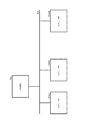
従来、図1に示すような構成においてネットワーク794を介してコンピュータ790#1、790#2、790#Nなどのホスト装置からの印刷データを印刷する複合機などの印刷装置792において、印刷装置792が少し離れた場所にある場合、印刷装置792の状態を把握しづらいため、印刷装置792の状態に従って予め決められた音声を再生することにより、印刷装置792の状態を音声通知により確認可能とし、特に、ユーザは自分が実行した印刷ジョブの完了を確認した上で印刷物を取りに行くことを望むため、印刷ジョブの完了がわかるように、印刷ジョブの完了を音声で通知し、音声通知により印刷ジョブの完了を確認可能とするのが一般的である。
Conventionally, in a
特許文献1では、個々の印刷ジョブに対応する印刷状況を音声により通知し、個々のユーザが印刷状況を容易に判断できるようにする手段が提案されている。
しかしながら、複数の印刷ジョブが連続で実行された場合には、印刷ジョブの完了毎に音声が通知されてしまい、音声が頻繁に鳴って騒がしくなってしまう場合があった。 However, when a plurality of print jobs are executed consecutively, a sound is notified each time the print job is completed, and the sound often sounds and becomes noisy.
具体例を図1に示す。複合機792は、ネットワーク794により接続されたコンピュータ790#1、790#2、...、790#Nなどからのプリントジョブの実行の要求に従って、プリントを実行する。そして、複合機792は、プリントジョブ(以下、単に「ジョブ」という。)が完了する度に、これをコンピュータ790#1、790#2、...、790#Nの利用者に知らせるためのジョブ終了音を利用者に届く程度のレベルで出力する。
A specific example is shown in FIG. The multifunction peripheral 792 includes
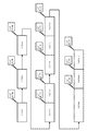
例えば、複合機は、図2に示すように、ジョブ#1からジョブ#11について、ジョブが連続していてもしていなくても、各ジョブが終了するたびに、ジョブ終了音を出力する。
For example, as shown in FIG. 2, the multifunction peripheral outputs a job end sound every time each job is completed, whether or not the jobs are continuous for
そこで、本発明は、それを知覚できる人の迷惑にならない程度にジョブに関連したものを出力するジョブ関連通知出力装置、複合機及び画像形成装置並びにジョブ関連通知出力方法を提供することを目的とする。 Accordingly, an object of the present invention is to provide a job-related notification output device, a multifunction peripheral, an image forming apparatus, and a job-related notification output method that output a job-related notification to the extent that the person who can perceive it does not bother the user. I do.
本発明によれば、
連続したジョブが終了した時に連続ジョブ終了を示す通知を出力する連続ジョブ終了通知手段と、
単独のジョブが終了した時に単独ジョブ終了を示す通知を出力する単独ジョブ終了通知手段と、
を備えることを特徴とするジョブ関連通知出力装置が提供される。
According to the present invention,
Continuous job end notifying means for outputting a notification indicating the end of the continuous job when the continuous job is completed,
A single job end notification unit that outputs a notification indicating the end of the single job when the single job ends,
And a job-related notification output device.
また、本発明によれば、上記のジョブ関連通知出力装置を備える複合機が提供される。 Further, according to the present invention, there is provided a multifunction peripheral including the above-described job-related notification output device.
更に、本発明によれば、上記のジョブ関連通知出力装置を備える画像形成装置が提供される。 Further, according to the present invention, there is provided an image forming apparatus including the above-described job-related notification output device.
更に、本発明によれば、
連続したジョブが終了した時に連続ジョブ終了を示す通知を出力する連続ジョブ終了通知ステップと、
単独のジョブが終了した時に単独ジョブ終了を示す通知を出力する単独ジョブ終了通知ステップと、
を有することを特徴とするジョブ関連通知出力方法が提供される。
Furthermore, according to the present invention,
A continuous job end notification step of outputting a notification indicating the end of the continuous job when the continuous job is completed;
A single job end notification step of outputting a notification indicating the end of the single job when the single job ends,
And a method for outputting a job-related notification.
更に、本発明によれば、コンピュータを上記のジョブ関連通知出力装置として機能させるためのプログラムが提供される。 Further, according to the present invention, there is provided a program for causing a computer to function as the job-related notification output device.
本発明によれば、出力したものがそれを知覚できる人の迷惑にならない。 According to the present invention, the output does not bother a person who can perceive it.
本発明によれば、 According to the present invention,
以下、図面を参照して本発明を実施するための形態について詳細に説明する。 Hereinafter, embodiments for carrying out the present invention will be described in detail with reference to the drawings.
[第1の実施の形態]
第1の実施形態によれば、複合機は、図3に示すように、ジョブが連続していれば、連続した最後のジョブが終了する度に連続ジョブ終了音を出力し、ジョブが連続していなければ、ジョブが終了する度に単独ジョブ終了音を出力する。従って、連続したジョブに含まれる最後のジョブ以外のジョブが終了したときにはジョブ終了音を出力しない。
[First Embodiment]
According to the first embodiment, as shown in FIG. 3, if the jobs are continuous, the multifunction peripheral outputs a continuous job end sound each time the last continuous job ends, and If not, an independent job end sound is output each time the job ends. Therefore, when a job other than the last job included in the continuous jobs is completed, no job end sound is output.
図3の例では、ジョブ#4とジョブ#5が連続しているので、ジョブ#4の終了時にはジョブ終了音を出力せず、ジョブ#5の終了時に連続ジョブ終了音を出力する。
In the example of FIG. 3, since the
また、ジョブ#6とジョブ#7とジョブ#8が連続しているので、ジョブ#6とジョブ#7の終了時にはジョブ終了音を出力せず、ジョブ#8の終了時に連続ジョブ終了音を出力する。 Also, since job # 6, job # 7, and job # 8 are continuous, a job end sound is not output at the end of job # 6 and job # 7, and a continuous job end sound is output at the end of job # 8. I do.
更に、ジョブ#9とジョブ#10とジョブ#11が連続しているので、ジョブ#9とジョブ#10の終了時にはジョブ終了音を出力せず、ジョブ#11の終了時に連続ジョブ終了音を出力する。
Further, since the
ジョブ#1、ジョブ#2及びジョブ#3は、連続しておらず、単独ジョブであるので、これらのジョブが終了する度に、単独ジョブ終了音を出力する。
Since the
また、ジョブ#9は、所定時間以上要したジョブであるので、長ジョブ終了音を出力する。
In addition, since the
次に、第1の実施の形態によるジョブ関連通知出力方法の説明をする。 Next, a method for outputting a job-related notification according to the first embodiment will be described.
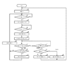
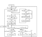
図4を参照すると、まず、連続するジョブの数を数えるための変数である「連続数」をゼロに初期化する(ステップS301)。 Referring to FIG. 4, first, a variable "continuous number" for counting the number of continuous jobs is initialized to zero (step S301).
ジョブが開始したならば(ステップS303でYES)、ジョブ長タイマをジョブ長タイマ用の所定値からスタートさせる(ステップS305)。この時点からジョブ長カウンターはカウントダウンを開始する。 If the job has started (YES in step S303), the job length timer is started from a predetermined value for the job length timer (step S305). From this point, the job length counter starts counting down.
次に、ジョブが完了したならば(ステップS307でYES)、ジョブ長タイマを停止させる(ステップS309)。 Next, if the job is completed (YES in step S307), the job length timer is stopped (step S309).
次に、ジョブ間隔タイマをジョブ間隔タイマ用の所定値からスタートさせる(ステップS311)。 Next, the job interval timer is started from a predetermined value for the job interval timer (step S311).
次に、次のジョブの開始又はジョブ間隔タイマのタイムアウトを待つ(ステップS313、S315)。 Next, it waits for the start of the next job or the timeout of the job interval timer (steps S313 and S315).
ジョブ間隔タイマがタイムアウトする前に次のジョブが開始したならば(ステップS313でYES)、ジョブ長タイマがタイムアウトしているかをみて、そうならば(ステップS317でYES)、長ジョブ終了音を出力する(ステップS319)。そして、連続数を1だけ増加させてから(ステップS321)、ステップS303に戻る。ステップS319では、単独ジョブ終了音を出力してもよい。 If the next job starts before the job interval timer times out (YES in step S313), it is determined whether the job length timer has timed out. If so (YES in step S317), a long job end sound is output. (Step S319). Then, after increasing the continuous number by 1 (step S321), the process returns to step S303. In step S319, a single job end sound may be output.
次のジョブが開始する前にジョブ間隔タイマがタイムアウトしたならば(ステップS315でYES)、「連続数」がゼロであるかをみて、そうならば(ステップS323でYES)、単独ジョブ終了音を出力してから(ステップS325)、ステップS301に戻る。「連続数」がゼロでなければ(ステップS323でNO)、連続ジョブ終了音を出力してから(ステップS327)、ステップS301に戻る。 If the job interval timer times out before the next job starts (YES in step S315), it is determined whether the “number of continuations” is zero. If so (YES in step S323), the single job end sound is output. After outputting (step S325), the process returns to step S301. If the “continuation number” is not zero (NO in step S323), a continuous job end sound is output (step S327), and the process returns to step S301.
[第2の実施の形態]
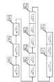
第2の実施形態によれば、複合機は、図5に示すように、ジョブが連続していれば、連続した最後のジョブが終了する度に連続ジョブ終了音を出力し、ジョブが連続していなければ、ジョブが終了する度に単独ジョブ終了音を出力する。従って、連続したジョブに含まれる最後のジョブ以外のジョブが終了したときにはジョブ終了音を出力しない。
[Second embodiment]
According to the second embodiment, as shown in FIG. 5, when jobs are continuous, the multifunction peripheral outputs a continuous job end sound each time the last continuous job ends, and If not, an independent job end sound is output each time the job ends. Therefore, when a job other than the last job included in the continuous jobs is completed, no job end sound is output.
また、第2の実施の形態においては、連続ジョブにおいて、ジョブのユーザが変化する度に前のユーザに対応したユーザ終了音を出力する。なお、例えば、ジョブを複合機に送ってきたコンピュータによりユーザを識別することができる。 In the second embodiment, in a continuous job, a user end sound corresponding to the previous user is output each time the user of the job changes. In addition, for example, the user who has sent the job to the multifunction peripheral can be identified by the computer.
図5の例では、ジョブ#4とジョブ#5が連続しているので、ジョブ#4の終了時にはジョブ終了音を出力せず、ジョブ#5の終了時に連続ジョブ終了音を出力する。
In the example of FIG. 5, since the
また、ジョブ#6とジョブ#7とジョブ#8が連続しているので、ジョブ#6とジョブ#7の終了時にはジョブ終了音を出力せず、ジョブ#8の終了時に連続ジョブ終了音を出力する。 Also, since job # 6, job # 7, and job # 8 are continuous, a job end sound is not output at the end of job # 6 and job # 7, and a continuous job end sound is output at the end of job # 8. I do.
更に、ジョブ#9とジョブ#10とジョブ#11が連続しているので、ジョブ#9とジョブ#10の終了時にはジョブ終了音を出力せず、ジョブ#11の終了時に連続ジョブ終了音を出力する。
Further, since the
ジョブ#4とジョブ#5は、連続するが、ジョブ#4のユーザはBであり、ジョブ#5のユーザはCであるので、ジョブ#4の終了時にユーザBの終了音を出力する。
ジョブ#6とジョブ#7とジョブ#8は、連続するが、ジョブ#6のユーザはCであり、ジョブ#7とジョブ#8のユーザはDであるので、ジョブ#6の終了時にユーザCの終了音を出力する。 Job # 6, job # 7, and job # 8 are continuous, but the user of job # 6 is C and the user of job # 7 and job # 8 is D. Outputs the end sound of.
ジョブ#9とジョブ#10とジョブ#11は、連続するが、ジョブ#9とジョブ#10のユーザはEであり、ジョブ#11のユーザはFであるので、ジョブ#10の終了時にユーザEの終了音を出力する。
ジョブ#1、ジョブ#2及びジョブ#3は、連続しておらず、単独ジョブであるので、これらのジョブが終了する度に、単独ジョブ終了音を出力する。
Since the
なお、単独ジョブにおいても、ユーザ終了音を出力してもよい。つまり、ジョブ#2の終了時にユーザAの終了音を出力してもよい。
Note that the user end sound may be output even in a single job. That is, the end sound of the user A may be output at the end of the
また、連続ジョブにおいても、ユーザ終了音を出力してもよい。 Also, in a continuous job, a user end sound may be output.
また、特定のユーザに対応した終了音の代わりに、単にユーザが変化したことを示す終了音を出力してもよい。 Further, instead of the end sound corresponding to the specific user, an end sound indicating that the user has changed may be simply output.
次に、第2の実施の形態によるジョブ関連通知出力方法の説明をする。 Next, a job-related notification output method according to the second embodiment will be described.
図6を参照すると、まず、連続するジョブの数を数えるための変数である「連続数」をゼロに初期化する(ステップS301)。 Referring to FIG. 6, first, a variable "continuous number" for counting the number of continuous jobs is initialized to zero (step S301).
ジョブが開始したならば(ステップS303でYES)、連続数が1以上且つ1つ前のジョブのユーザIDと現在のジョブのユーザIDが異なるか
をみて、そうならば(ステップS331でYES、ステップS333でYES)、前のユーザに対応したジョブ終了音を出力する(ステップS335)。特定のユーザに対応しないジョブ終了音を出力してもよい。
If the job has started (YES in step S303), it is determined whether the user ID of the job whose number of continuations is 1 or more and the previous job is different from the user ID of the current job, and if so (YES in step S331, step (YES in S333), and outputs a job end sound corresponding to the previous user (step S335). A job end sound that does not correspond to a specific user may be output.
次に、現在のジョブのユーザIDを記憶する(ステップS337)。 Next, the user ID of the current job is stored (step S337).
次に、ジョブ長タイマをジョブ長タイマ用の所定値からスタートさせる(ステップS305)。この時点からジョブ長カウンターはカウントダウンを開始する。 Next, the job length timer is started from a predetermined value for the job length timer (step S305). From this point, the job length counter starts counting down.
次に、ジョブが完了したならば(ステップS307でYES)、ジョブ長タイマを停止させる(ステップS309)。 Next, if the job is completed (YES in step S307), the job length timer is stopped (step S309).
次に、ジョブ間隔タイマをジョブ間隔タイマ用の所定値からスタートさせる(ステップS311)。 Next, the job interval timer is started from a predetermined value for the job interval timer (step S311).
次に、次のジョブの開始又はジョブ間隔タイマのタイムアウトを待つ(ステップS313、S315)。 Next, it waits for the start of the next job or the timeout of the job interval timer (steps S313 and S315).
ジョブ間隔タイマがタイムアウトする前に次のジョブが開始したならば(ステップS313でYES)、ジョブ長タイマがタイムアウトしているかをみて、そうならば(ステップS317でYES)、長ジョブ終了音を出力する(ステップS319)。そして、連続数を1だけ増加させてから(ステップS321)、ステップS303に戻る。ステップS319では、単独ジョブ終了音を出力してもよい。 If the next job starts before the job interval timer times out (YES in step S313), it is determined whether the job length timer has timed out. If so (YES in step S317), a long job end sound is output. (Step S319). Then, after increasing the continuous number by 1 (step S321), the process returns to step S303. In step S319, a single job end sound may be output.
次のジョブが開始する前にジョブ間隔タイマがタイムアウトしたならば(ステップS315でYES)、「連続数」がゼロであるかをみて、そうならば(ステップS323でYES)、単独ジョブ終了音を出力してから(ステップS325)、ステップS301に戻る。「連続数」がゼロでなければ(ステップS323でNO)、連続ジョブ終了音を出力してから(ステップS327)、ステップS301に戻る。 If the job interval timer times out before the next job starts (YES in step S315), it is determined whether the “number of continuations” is zero. If so (YES in step S323), the single job end sound is output. After outputting (step S325), the process returns to step S301. If the “continuation number” is not zero (NO in step S323), a continuous job end sound is output (step S327), and the process returns to step S301.
単独ジョブでもユーザ終了音を出力するためには、ステップS331での判断を常にYESにする。 In order to output the user end sound even in a single job, the determination in step S331 is always YES.
[第3の実施の形態]
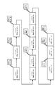
第3の実施形態によれば、複合機は、図7に示すように、ジョブが連続していれば、連続した最後のジョブが終了する度に連続ジョブ終了音を出力し、ジョブが連続していなければ、ジョブが終了する度に単独ジョブ終了音を出力する。従って、連続したジョブに含まれる最後のジョブ以外のジョブが終了したときにはジョブ終了音を出力しない。
[Third Embodiment]
According to the third embodiment, as shown in FIG. 7, if the jobs are continuous, the multifunction peripheral outputs a continuous job end sound each time the last continuous job ends, and If not, an independent job end sound is output each time the job ends. Therefore, when a job other than the last job included in the continuous jobs is completed, no job end sound is output.
また、第3の実施の形態においては、連続ジョブにおいて、ジョブのユーザが変化する度に今回のユーザに対応したユーザ終了音を出力する。 In the third embodiment, in a continuous job, a user end sound corresponding to the current user is output each time the user of the job changes.
図7の例では、ジョブ#4とジョブ#5が連続しているので、ジョブ#4の終了時にはジョブ終了音を出力せず、ジョブ#5の終了時に連続ジョブ終了音を出力する。
In the example of FIG. 7, since the
また、ジョブ#6とジョブ#7とジョブ#8が連続しているので、ジョブ#6とジョブ#7の終了時にはジョブ終了音を出力せず、ジョブ#8の終了時に連続ジョブ終了音を出力する。 Also, since job # 6, job # 7, and job # 8 are continuous, a job end sound is not output at the end of job # 6 and job # 7, and a continuous job end sound is output at the end of job # 8. I do.
更に、ジョブ#9とジョブ#10とジョブ#11が連続しているので、ジョブ#9とジョブ#10の終了時にはジョブ終了音を出力せず、ジョブ#11の終了時に連続ジョブ終了音を出力する。
Further, since the
ジョブ#4とジョブ#5は、連続するが、ジョブ#4のユーザはBであり、ジョブ#5のユーザはCであるので、ジョブ#4の終了時(すなわち、ジョブ#5の開始時)にユーザCの開始音を出力する。
ジョブ#6とジョブ#7とジョブ#8は、連続するが、ジョブ#6のユーザはCであり、ジョブ#7とジョブ#8のユーザはDであるので、ジョブ#6の終了時(すなわち、ジョブ#7の開始時)にユーザDの開始音を出力する。 Job # 6, job # 7 and job # 8 are continuous, but the user of job # 6 is C and the user of job # 7 and job # 8 is D. , At the start of job # 7).
ジョブ#9とジョブ#10とジョブ#11は、連続するが、ジョブ#9とジョブ#10のユーザはEであり、ジョブ#11のユーザはFであるので、ジョブ#10の終了時(すなわち、ジョブ#11の開始時)にユーザFの終了音を出力する。
ジョブ#1、ジョブ#2及びジョブ#3は、連続しておらず、単独ジョブであるので、これらのジョブが終了する度に、単独ジョブ終了音を出力する。
Since the
なお、単独ジョブにおいても、ユーザ終了音を出力してもよい。つまり、ジョブ#3の開始時にユーザBの終了音を出力してもよい。 Note that the user end sound may be output even in a single job. That is, the end sound of the user B may be output at the start of the job # 3.
また、特定のユーザに対応した開始音の代わりに、単にユーザが変化したことを示す開始音を出力してもよい。 Further, instead of a start sound corresponding to a specific user, a start sound indicating that the user has changed may be output.
次に、第3の実施の形態によるジョブ関連通知出力方法の説明をする。 Next, a job-related notification output method according to the third embodiment will be described.
第2の実施形態に対応する図6と第3の実施形態に対応する図8より明らかなように、第3の実施の形態は、第2の実施の形態と比較し、前のユーザに対応したジョブ終了音を出力するステップS335が、現在のユーザに対応したジョブ開始音を出力するステップS339に置き換わる点のみが異なる。他のステップは、共通であるので、重複する説明を省略する。 As is clear from FIG. 6 corresponding to the second embodiment and FIG. 8 corresponding to the third embodiment, the third embodiment is different from the second embodiment in that it corresponds to the previous user. The only difference is that step S335 of outputting the completed job end sound is replaced with step S339 of outputting the job start sound corresponding to the current user. The other steps are common, and duplicate description will be omitted.
ステップS339では、特定のユーザに対応しないジョブ開始音を出力してもよい。 In step S339, a job start sound that does not correspond to a specific user may be output.
[第4の実施の形態]
第4の実施形態によれば、複合機は、図9に示すように、ジョブが連続していれば、連続した最後のジョブが終了する度に連続ジョブ終了音を出力し、ジョブが連続していなければ、ジョブが終了する度に単独ジョブ終了音を出力する。従って、連続したジョブに含まれる最後のジョブ以外のジョブが終了したときにはジョブ終了音を出力しない。
[Fourth Embodiment]
According to the fourth embodiment, as shown in FIG. 9, if the jobs are continuous, the multifunction peripheral outputs a continuous job end sound each time the last continuous job ends, and If not, an independent job end sound is output each time the job ends. Therefore, when a job other than the last job included in the continuous jobs is completed, no job end sound is output.
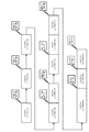
また、第4の実施の形態においては、連続ジョブにおいて、関連ジョブが終了する度に前の関連ジョブに対応した関連ジョブ終了音を出力する。 In the fourth embodiment, in a continuous job, a related job end sound corresponding to the previous related job is output each time the related job ends.
図9の例では、ジョブ#4とジョブ#5が連続しているので、ジョブ#4の終了時にはジョブ終了音を出力せず、ジョブ#5の終了時に連続ジョブ終了音を出力する。
In the example of FIG. 9, since the
また、ジョブ#6とジョブ#7とジョブ#8が連続しているので、ジョブ#6とジョブ#7の終了時にはジョブ終了音を出力せず、ジョブ#8の終了時に連続ジョブ終了音を出力する。 Also, since job # 6, job # 7, and job # 8 are continuous, a job end sound is not output at the end of job # 6 and job # 7, and a continuous job end sound is output at the end of job # 8. I do.
更に、ジョブ#9とジョブ#10とジョブ#11が連続しているので、ジョブ#9とジョブ#10の終了時にはジョブ終了音を出力せず、ジョブ#11の終了時に連続ジョブ終了音を出力する。
Further, since the
ジョブ#4とジョブ#5は、連続するが、ジョブ#4の関連付けIDがQ2でありジョブ#5の関連付けIDがR1であり、ジョブ#4とジョブ#5の関連性がないので、ジョブ#4の終了時に関連ジョブQの終了音を出力する。
ジョブ#6とジョブ#7とジョブ#8は、連続するが、ジョブ#6の関連付けIDがR1であり、ジョブ#7の関連付けIDがS1でありジョブ#8の関連付けIDがS2であり、ジョブ#6とジョブ#7の関連性がないので、ジョブ#6の終了時に関連ジョブRの終了音を出力する。 Job # 6, job # 7, and job # 8 are continuous, but the association ID of job # 6 is R1, the association ID of job # 7 is S1, the association ID of job # 8 is S2, Since there is no relationship between # 6 and job # 7, the end sound of the related job R is output when the job # 6 ends.
ジョブ#9とジョブ#10とジョブ#11は、連続するが、ジョブ#9の関連付けIDがNULLでありジョブ#10の関連付けIDがNULLでありジョブ#11の関連付けIDがU1であり、ジョブ#10とジョブ#11の関連性がない。しかし、もともと、ジョブ#10は他のジョブと関連付いていないので、ジョブ#10の終了時に関連ジョブ終了音を出力しない。
ジョブ#1、ジョブ#2及びジョブ#3は、連続しておらず、単独ジョブであるので、これらのジョブが終了する度に、単独ジョブ終了音を出力する。
Since the
なお、もともと他のジョブと関連付いていないジョブが終了し、次から相互に関連したジョブが開始するときに関連ジョブ開始音を出力してもよい。図9の例では、ジョブ#10の終了時に例えばNULLに対応した関連ジョブ終了音を出力してもよい。
Note that a related job start sound may be output when a job that is not originally related to another job ends and a mutually related job starts from the next time. In the example of FIG. 9, when the
次に、第4の実施の形態によるジョブ関連通知出力方法の説明をする。 Next, a job-related notification output method according to the fourth embodiment will be described.
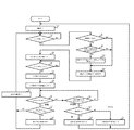
図10を参照すると、まず、連続するジョブの数を数えるための変数である「連続数」をゼロに初期化する(ステップS301)。 Referring to FIG. 10, first, a variable "continuous number" for counting the number of continuous jobs is initialized to zero (step S301).
ジョブが開始したならば(ステップS303でYES)、連続数が1以上且つ1つ前のジョブの関連付けIDと現在のジョブの関連付けIDがジョブ相互間の関連性を示しているかをみて、そうでないならば(ステップS341でYES、ステップS343でNO)、前の関連付けIDに対応したジョブ終了音を出力する(ステップS345)。 If the job has started (YES in step S303), it is determined whether or not the association ID of the job having the consecutive number of 1 or more and the immediately preceding job and the association ID of the current job indicate the association between the jobs. If it is (YES in step S341, NO in step S343), a job end sound corresponding to the previous association ID is output (step S345).
なお、関連付けがないときの関連付けIDの値を所定値としておいて、関連付けIDがあるときの関連付けIDをそれ以外の何れかの値としている。相互に関連付けられているジョブの関連付けIDの値は同一又は関連付けられていることがそれから判断できるような値を持つ。コンピュータにおいて、同一のフォルダにあるファイルの印刷ジョブが関連付けられていると判断してもよいし、同一の日付のファイルの印刷ジョブが関連付けられていると判断してもよいし、同一の種類のファイルが関連付けられていると判断してもよいし、同一のアプリケーションのファイルが関連付けられていると判断してもよいし、これらの組合わせにより関連付けられているか否かを判断してもよいし、利用者や所定のアプリケーションにより設定された関連付けIDにより関連付けられているか否かを判断してもよい。 Note that the value of the association ID when there is no association is set as a predetermined value, and the association ID when there is an association ID is any other value. The values of the association IDs of the jobs that are associated with each other have a value that can be determined from the fact that they are the same or associated. The computer may determine that print jobs of files in the same folder are associated with each other, may determine that print jobs of files with the same date are associated with each other, It may be determined that the files are associated with each other, may be determined that the files of the same application are associated, or may be determined by a combination of these. Alternatively, it may be determined whether or not they are associated with each other by an association ID set by a user or a predetermined application.
ステップS345において、前の関連付けIDがNULLであるならば、NULLに対応したジョブ終了音を出力してもよいし、何も出力しなくてもよい。 In step S345, if the previous association ID is NULL, a job end sound corresponding to NULL may be output or nothing may be output.
次に、現在のジョブの関連付けIDを記憶する(ステップS337)。 Next, the association ID of the current job is stored (step S337).
次に、ジョブ長タイマをジョブ長タイマ用の所定値からスタートさせる(ステップS305)。この時点からジョブ長カウンターはカウントダウンを開始する。 Next, the job length timer is started from a predetermined value for the job length timer (step S305). From this point, the job length counter starts counting down.
次に、ジョブが完了したならば(ステップS307でYES)、ジョブ長タイマを停止させる(ステップS309)。 Next, if the job is completed (YES in step S307), the job length timer is stopped (step S309).
次に、ジョブ間隔タイマをジョブ間隔タイマ用の所定値からスタートさせる(ステップS311)。 Next, the job interval timer is started from a predetermined value for the job interval timer (step S311).
次に、次のジョブの開始又はジョブ間隔タイマのタイムアウトを待つ(ステップS313、S315)。 Next, it waits for the start of the next job or the timeout of the job interval timer (steps S313 and S315).
ジョブ間隔タイマがタイムアウトする前に次のジョブが開始したならば(ステップS313でYES)、ジョブ長タイマがタイムアウトしているかをみて、そうならば(ステップS317でYES)、長ジョブ終了音を出力する(ステップS319)。そして、連続数を1だけ増加させてから(ステップS321)、ステップS303に戻る。ステップS319では、単独ジョブ終了音を出力してもよい。 If the next job starts before the job interval timer times out (YES in step S313), it is determined whether the job length timer has timed out. If so (YES in step S317), a long job end sound is output. (Step S319). Then, after increasing the continuous number by 1 (step S321), the process returns to step S303. In step S319, a single job end sound may be output.
次のジョブが開始する前にジョブ間隔タイマがタイムアウトしたならば(ステップS315でYES)、「連続数」がゼロであるかをみて、そうならば(ステップS323でYES)、単独ジョブ終了音を出力してから(ステップS325)、ステップS301に戻る。「連続数」がゼロでなければ(ステップS323でNO)、連続ジョブ終了音を出力してから(ステップS327)、ステップS301に戻る。 If the job interval timer times out before the next job starts (YES in step S315), it is determined whether the “number of continuations” is zero. If so (YES in step S323), the single job end sound is output. After outputting (step S325), the process returns to step S301. If the “continuation number” is not zero (NO in step S323), a continuous job end sound is output (step S327), and the process returns to step S301.
[第5の実施の形態]
第5の実施形態によれば、複合機は、図11に示すように、ジョブが連続していれば、連続した最後のジョブが終了する度に連続ジョブ終了音を出力し、ジョブが連続していなければ、ジョブが終了する度に単独ジョブ終了音を出力する。従って、連続したジョブに含まれる最後のジョブ以外のジョブが終了したときにはジョブ終了音を出力しない。
[Fifth Embodiment]
According to the fifth embodiment, as shown in FIG. 11, if the jobs are continuous, the multifunction peripheral outputs a continuous job end sound each time the last continuous job ends, and If not, an independent job end sound is output each time the job ends. Therefore, when a job other than the last job included in the continuous jobs is completed, no job end sound is output.
また、第5の実施の形態においては、連続ジョブにおいて、関連ジョブが終了する度に前の関連ジョブに対応した関連ジョブ終了音を出力する。 In the fifth embodiment, in a continuous job, a related job end sound corresponding to the previous related job is output each time the related job ends.
図11の例では、ジョブ#4とジョブ#5が連続しているので、ジョブ#4の終了時にはジョブ終了音を出力せず、ジョブ#5の終了時に連続ジョブ終了音を出力する。
In the example of FIG. 11, since the
また、ジョブ#6とジョブ#7とジョブ#8が連続しているので、ジョブ#6とジョブ#7の終了時にはジョブ終了音を出力せず、ジョブ#8の終了時に連続ジョブ終了音を出力する。 Also, since job # 6, job # 7, and job # 8 are continuous, a job end sound is not output at the end of job # 6 and job # 7, and a continuous job end sound is output at the end of job # 8. I do.
更に、ジョブ#9とジョブ#10とジョブ#11が連続しているので、ジョブ#9とジョブ#10の終了時にはジョブ終了音を出力せず、ジョブ#11の終了時に連続ジョブ終了音を出力する。
Further, since the
ジョブ#4とジョブ#5は、連続するが、ジョブ#4の関連付けIDがQ2でありジョブ#5の関連付けIDがR1であり、ジョブ#4とジョブ#5の関連性がない。しかし、もともと、ジョブ#5は他のジョブと関連付いていないので、ジョブ#5の開始時に関連ジョブ開始音を出力しない。
ジョブ#6とジョブ#7とジョブ#8は、連続するが、ジョブ#6の関連付けIDがNULLであり、ジョブ#7の関連付けIDがS1であり、ジョブ#8の関連付けIDがS2であり、ジョブ#6とジョブ#7の関連性がないので、ジョブ#7の開始時に関連ジョブSの開始音を出力する。 The job # 6, the job # 7, and the job # 8 are continuous, but the association ID of the job # 6 is NULL, the association ID of the job # 7 is S1, the association ID of the job # 8 is S2, Since there is no relationship between job # 6 and job # 7, a start sound of related job S is output when job # 7 is started.
ジョブ#9とジョブ#10とジョブ#11は、連続するが、ジョブ#9の関連付けIDがT1であり、ジョブ#10の関連付けIDがT2であり、ジョブ#11の関連付けIDがU1であり、ジョブ#10とジョブ#11の関連性がない。従って、ジョブ#11の開始時に関連ジョブUの開始音を出力する。
ジョブ#1、ジョブ#2及びジョブ#3は、連続しておらず、単独ジョブであるので、これらのジョブが終了する度に、単独ジョブ終了音を出力する。
Since the
なお、相互に関連したジョブが終了し、もともと他のジョブと関連付いていないジョブが開始するときに関連ジョブ開始音を出力してもよい。図11の例では、ジョブ#5の開始時に例えばNULLに対応した関連ジョブ開始音を出力してもよい。 Note that a related job start sound may be output when a mutually related job ends and a job that is not originally related to another job starts. In the example of FIG. 11, at the start of the job # 5, for example, a related job start sound corresponding to NULL may be output.
次に、第5の実施の形態によるジョブ関連通知出力方法の説明をする。 Next, a job-related notification output method according to the fifth embodiment will be described.
第4の実施形態に対応する図10と第5の実施形態に対応する図12より明らかなように、第5の実施の形態は、第4の実施の形態と比較し、前の関連付けIDに対応したジョブ終了音を出力するステップS345が、現在の関連付けIDに対応したジョブ開始音を出力するステップS349に置き換わる点が異なる。 As is clear from FIG. 10 corresponding to the fourth embodiment and FIG. 12 corresponding to the fifth embodiment, the fifth embodiment is different from the fourth embodiment in that a previous association ID is used. The difference is that step S345 for outputting the corresponding job end sound is replaced with step S349 for outputting the job start sound corresponding to the current association ID.
また、ステップS349において、次の関連付けIDがNULLであるならば、NULLに対応したジョブ開始音を出力してもよいし、何も出力しなくてもよい。 In step S349, if the next association ID is NULL, a job start sound corresponding to NULL may be output, or nothing may be output.
他のステップは、共通であるので、重複する説明を省略する。 The other steps are common, and duplicate description will be omitted.
[第6の実施の形態]
複合機の設定により、第1の実施の形態乃至第5の実施の形態の何れかを選択することができるようにしてもよい。特に、同一の複合機において、管理者又は利用者による設定により、何れかを選択できるようにしてもよい。
[Sixth Embodiment]
Any of the first to fifth embodiments may be selected by setting the multifunction peripheral. In particular, in the same multifunction peripheral, either one may be selected by a setting by an administrator or a user.
但し、第2の実施の形態と第3の実施の形態は相互に排他的に選択することが通常であり、第4の実施の形態と第5の実施の形態も相互に排他的に選択することが通常である。 However, it is usual that the second and third embodiments are mutually exclusively selected, and the fourth and fifth embodiments are also mutually exclusively selected. That is normal.
フローチャートには示していないが、第2の実施の形態におけるステップS331からステップS337と第4の実施の形態におけるステップS341からステップS347の双方を実行してもよい。つまり、利用者が変更することに係る通知と、関連したジョブの開始又は終了に係る通知を同時に実行してもよい。同様に、第2の実施の形態と第5の実施形態の組合わせ、第3の実施形態と第4の実施形態の組合わせ、及び第3の実施形態と第5の実施形態の組合わせなどを構成することができる。複数種類の通知が同一ジョブの開始時又は終了時に重複するならば、時間をずらして全部出力してもよいし、所定の優先順位に従って、一部のみを有効化してもよい。 Although not shown in the flowchart, both steps S331 to S337 in the second embodiment and steps S341 to S347 in the fourth embodiment may be executed. That is, the notification about the change by the user and the notification about the start or end of the related job may be executed at the same time. Similarly, a combination of the second embodiment and the fifth embodiment, a combination of the third embodiment and the fourth embodiment, a combination of the third embodiment and the fifth embodiment, and the like. Can be configured. If a plurality of types of notifications overlap at the start or end of the same job, all the notifications may be output at different times or only some of them may be enabled according to a predetermined priority.
[第7の実施の形態]
第1乃至第6の実施の形態によるジョブ関連通知出力方法を実行するための第7の実施の形態によるジョブ関連出力装置の構成を示す機能ブロック図を図13に示す。
[Seventh Embodiment]
FIG. 13 is a functional block diagram showing a configuration of a job-related output device according to the seventh embodiment for executing the job-related notification output methods according to the first to sixth embodiments.
図13を参照すると、ジョブ関連出力装置101は、印刷ジョブデータ解析部111、ジョブ間隔検出部113、ジョブ長検出部115、ユーザ判定部117、関連ジョブ判定部119、連続ジョブ終了通知部121、単独ジョブ終了通知部123、ユーザ変更通知部125、関連ジョブ開始通知部127、関連ジョブ終了通知部129、長ジョブ終了通知部131及び音声出力部133を含む。
Referring to FIG. 13, the job-related
印刷ジョブデータ解析部111は、印刷ジョブデータを入力して、それを解析する。
The print job
ジョブ間隔検出部113は、ジョブとそれに続くジョブの時間間隔を検出する。特に、その時間間隔が所定値以下であるか否かを検出する。
The job
ジョブ長検出部115は、各ジョブの時間的な長さを検出する。特に、各ジョブの時間的な長さが所定長以上か否かを検出する。
The job
ユーザ判定部117は、各ジョブに含まれるユーザIDなどに基づいて各ジョブのユーザを判定する。
The
関連ジョブ判定部119は、各ジョブに含まれる関連付けIDに基づいて、ジョブが関連するか否かを判定する。
The related
連続ジョブ終了通知部121は、連続したジョブが終了した時に、それを示す音を出力する。音声の種類をそれを示すためのものにすることや、音声によってそれを示すことができる。
The continuous job
単独ジョブ終了通知部123は、単独ジョブが終了した時に、それを示す音を出力する。音声の種類をそれを示すためのものにすることや、音声によってそれを示すことができる。
The single job
ユーザ変更通知部125は、ユーザが変更した時に、それを示す音を出力する。音声の種類をそれを示すためのものにすることや、音声によってそれを示すことができる。特に、特定のユーザを表すために、そのユーザに対応した種類の音を用いたり、ユーザ名の音声を用いてもよい。
The user
関連ジョブ開始通知部127は、関連ジョブが開始した時に、それを示す音を出力する。音声の種類をそれを示すためのものにすることや、音声によってそれを示すことができる。
The related job start notifying
関連ジョブ終了通知部129は、関連ジョブが終了した時に、それを示す音を出力する。音声の種類をそれを示すためのものにすることや、音声によってそれを示すことができる。
The related job
長ジョブ終了通知部131は、長ジョブが終了した時に、それを示す音を出力する。音声の種類をそれを示すためのものにすることや、音声によってそれを示すことができる。
The long job
音声出力部133は、連続ジョブ終了通知部121、単独ジョブ終了通知部123、ユーザ変更通知部125、関連ジョブ開始通知部127、関連ジョブ終了通知部129及び長ジョブ終了通知部131が出力しようとする音を出力する。
The
[第8の実施の形態]
第8の実施の形態は、第7の実施の形態によるジョブ関連出力装置を含む複合機800に関するものである。図14及び図15は、複合機800の構成などを示すものである。
[Eighth Embodiment]
The eighth embodiment relates to a multifunction peripheral 800 including the job-related output device according to the seventh embodiment. 14 and 15 show the configuration of the multifunction peripheral 800 and the like.
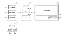
図14及び図15に示すように、複合機800は、原稿の画像を読み取る原稿読取装置820と、シートに画像を形成する複合機本体(画像形成部本体)830と、原稿読取装置820及び複合機本体830を操作するための操作パネル部843と、操作パネル部843による操作に基づいて原稿読取装置820及び複合機本体830を制御する演算処理部841と、を備えている。
As shown in FIGS. 14 and 15, the multifunction peripheral 800 includes a
画像読取りのために原稿読取装置820を単体で用いること、画像形成のために複合機本体830を単体で用いることの他に、画像を複写するためにこれらを連動させることもできる。また、複合機800は図示しない記憶装置及びファクシミリ装置を含んでいてもよい。記憶装置は、原稿読取装置820により読み取られた画像やファクシミリ装置により受信した画像を格納することができる。ファクシミリ装置は、原稿読取装置820により読み取られた画像や記憶装置に格納されている画像を送信することと、外部から画像を受信することができる。更に、複合機800は、ネットワークを介してパーソナルコンピュータと接続するためのインターフェースを含んでいてもよい。複合機800に接続されたパーソナルコンピュータは、これが管理できるデータについて複合機の機能を利用することができる。
In addition to using the
原稿読取装置820は、原稿を自動給送する原稿自動給送部SPF(Single Pass Feeder)824と、原稿の画像を読み取る読取装置本体822と、を備えている。なお、原稿読取装置820は、図15に示す構成要素の他に、図15は示されないが図14に示される構成要素も含む。また、図14に示すように、読取装置本体822には、原稿台826が備わる。
The
複合機本体830は、シートを給送するシート給送部10と、シートを手差し給送可能な手差し給送部20と、シート給送部10又は手差し給送部20により給送されるシートに画像を形成する画像形成部30と、を備えている。
The MFP
シート給送部10は、シートを積載するシート積載部11と、シート積載部11に積載されたシートを1枚ずつ分離給送する分離給送部12と、を備えている。シート積載部11は、回転軸13を中心に回動する中板14を備えており、中板14は、シートを給送する際に回動してシートを上方に持ち上げる。分離給送部12は、中板14により持ち上げられたシートを給送するピックアップローラ15と、ピックアップローラ15により給送されるシートを1枚ずつに分離する分離ローラ対16と、を備えている。
The
手差し給送部20は、シートを積載可能な手差しトレイ21と、手差しトレイ21に積載されたシートを1枚ずつ分離給送する分離給送部22と、を備えている。手差しトレイ21は、複合機本体830に回動自在に支持されており、手差し給送する際には、所定の角度に固定させることでシートを積載可能になる。分離給送部22は、手差しトレイ21に積載されたシートを給送するピックアップローラ23と、ピックアップローラ23により給送されるシートを1枚ずつに分離する分離ローラ24及び分離パッド25と、を備えている。
The
画像形成部30は、イエロー(Y)、マゼンタ(M)、シアン(C)、ブラック(K)の画像を形成する4つのプロセスカートリッジ31Y〜31Kと、後述する感光体ドラム740Y〜740Kと、これらの表面を露光する露光装置32と、感光体ドラム740Y〜740Kの表面に形成されたトナー像をシートに転写する転写部(転写手段)33と、転写したトナー像をシートに定着させる定着部34と、を備えている。なお、符号の最後に付すアルファベット(Y、M、C、K)は、それぞれの色(イエロー、マゼンタ、シアン、ブラック)を示している。
The
4つのプロセスカートリッジ31Y〜31Kのそれぞれは、複合機本体830から取り外し可能に構成されており、交換可能となっている。なお、4つのプロセスカートリッジ31Y〜31Kは、形成する画像の色が異なること以外は同様な構成であるため、イエロー(Y)の画像を形成するプロセスカートリッジ31Yの構成のみの説明し、プロセスカートリッジ31M〜31Kの説明は省略する。
Each of the four process cartridges 31 </ b> Y to 31 </ b> K is configured to be detachable from the MFP
プロセスカートリッジ31Yは、像担持体としての感光体ドラム740Yと、感光体ドラム740Yを帯電させる帯電器741Yと、感光体ドラム740Y上に形成された静電潜像を現像する現像装置742Yと、感光体ドラム740Yの表面に残留するトナーを除去するドラムクリーナと、を備えている。現像装置742Yは、感光体ドラム740Yを現像する現像装置本体(詳細には図示せず)と、現像装置本体にトナーを供給するトナーカートリッジ(詳細には図示せず)と、を備えている。トナーカートリッジは、現像装置本体に着脱可能に構成されており、収容されたトナーが無くなると、現像装置本体から取り外して、交換することができるようになっている。
The process cartridge 31Y includes a photosensitive drum 740Y as an image carrier, a charger 741Y for charging the photosensitive drum 740Y, a developing
露光装置32は、レーザ光を照射する光源(図示せず)と、レーザ光を感光体ドラム740Y〜740Kに導く複数のミラー(図示せず)等と、を備えている。転写部33は、感光体ドラム740Y〜740Kに形成されたトナー像を担持する中間転写ベルト35と、感光体ドラム740Y〜740Kに形成されたトナー像を中間転写ベルト35に一次転写する一次転写ローラ36Y〜36Kと、中間転写ベルト35に転写されたトナー像をシートに二次転写する二次転写ローラ37と、中間転写ベルト35に残留するトナーを除去するベルトクリーナ38と、を備えている。中間転写ベルト35は、駆動ローラ39a及び従動ローラ39bに掛け渡されており、一次転写ローラ36Y〜36Kによって感光体ドラム740Y〜740Kに押し付けられている。二次転写ローラ37は、駆動ローラ39aとで中間転写ベルト35をニップ(挟持)しており、ニップ部Nで中間転写ベルト35が担持するトナー像をシートに転写する。定着部34は、シートを加熱する加熱ローラ34aと、加熱ローラ34aに圧接する加圧ローラ34bと、を備えている。
The
操作パネル部843は、所定の情報を表示する表示部845と、利用者が原稿読取装置820及び複合機本体830への指示を入力する入力部847と、を備えている。本実施形態においては、操作パネル部843は、読取装置本体822の正面側に配設されている。なお、正面側は図14の紙面の手前側に対応し、裏面側は図14の背面側に対応する。
The
図15に示すように、演算処理部841は、シート給送部10、手差し給送部20、画像形成部30及び原稿読取装置820を駆動制御するCPU841aと、CPU841aを動作させるための各種プログラムとCPU841aが用いる各種情報等を記憶するメモリ841bと、を備えている。演算処理部841は、利用者による操作パネル部843への操作に基づいて、シート給送部10、手差し給送部20、画像形成部30及び原稿読取装置820の動作を統合して制御し、シートに画像を形成させる。
As illustrated in FIG. 15, the
次に、上述のように構成された複合機800による画像形成動作(演算処理部841による画像形成制御)について説明する。本実施形態においては、原稿自動給送部824により給送され、読取装置本体822により読み取られた読取原稿の画像を、シート給送部10により給送されるシートに画像形成部30が形成する画像形成動作を例にとり説明する。
Next, an image forming operation (image forming control by the arithmetic processing unit 841) by the
利用者による操作パネル部843の入力部847への入力により、画像形成開始信号が発信されると、利用者により原稿自動給送部824に載置された読取原稿が原稿読取位置に向けて自動給送され、原稿読取位置で読取装置本体822によって画像が読み取られる。
When an image formation start signal is transmitted by an input to the
読取装置本体822により原稿の画像が読み取られると、読み取られた原稿の画像情報に基づいて、露光装置32が感光体ドラム740Y〜740Kに向けて、それぞれに対応する複数のレーザ光を照射する。このとき、感光体ドラム740Y〜740Kは、それぞれ、帯電器741Y〜741Kにより予め帯電されており、それぞれに対応するレーザ光が照射されることで感光体ドラム740Y〜740K上にそれぞれの静電潜像が形成される。その後、現像装置742Y〜742Kにより感光体ドラム740Y〜740K上にそれぞれ形成された静電潜像が現像され、感光体ドラム740Y〜740K上に、イエロー(Y)、マゼンタ(M)、シアン(C)及びブラック(K)のトナー像が形成される。感光体ドラム740Y〜740K上に形成された各色のトナー像は、一次転写ローラ36Y〜36Kによって中間転写ベルト35に重畳転写され、重畳転写されたトナー像(フルカラーのトナー像)は、中間転写ベルト35に担持された状態でニップ部Nまで搬送される。
When the image of the document is read by the reading device
上述の画像形成動作に並行して、シート積載部11に積載されたシートが、分離給送部12によって1枚ずつに分離されながら、ピックアップローラ15によりシート搬送路26に給送される。そして、ニップ部Nのシート搬送方向上流にあるレジストローラ対27で、斜行が補正されると共に、所定の搬送タイミングでニップ部Nに搬送される。ニップ部Nに搬送されたシートは、二次転写ローラ37によって中間転写ベルト35が担持するフルカラーのトナー像が転写される。
In parallel with the above-described image forming operation, the sheets stacked on the sheet stacking unit 11 are fed to the sheet conveyance path 26 by the
トナー像が転写されたシートは、定着部34で加熱・加圧されることでトナー像が溶融定着され、排出ローラ対18により装置外に排出される。装置外に排出されたシートは、排出シート積載部19に積載される。
The sheet to which the toner image has been transferred is heated and pressed by the fixing
なお、シートの両面(第1面及び第2面)に画像を形成する場合には、第1面に画像が形成されたシートが装置外に排出される前に、排出ローラ対18を逆回転させて両面搬送路17に搬送し、両面搬送路17を介して画像形成部30に再搬送する。そして、第1面と同様に、第2面に画像を形成し、装置外に排出する。装置外に排出されたシートは、排出シート積載部19に積載される。
When images are formed on both sides (first and second surfaces) of the sheet, the
上記の実施形態では、プリントジョブに関連した説明をしたが、他の種類のジョブにもこれらの実施形態を適用することができる。 Although the above embodiments have been described with reference to print jobs, these embodiments can be applied to other types of jobs.
また、複合機以外の装置にも適用することができる。 Further, the present invention can be applied to devices other than the multifunction peripheral.
更に、出力するものは、音声でなくてもよい。例えば、画像や文字であってもよい。 Furthermore, what is output may not be audio. For example, it may be an image or a character.
なお、上記のジョブ関連出力装置は、ハードウェア、ソフトウェア又はこれらの組合わせにより実現することができる。また、上記のジョブ関連出力装置により行なわれるジョブ関連通知出力方法も、ハードウェア、ソフトウェア又はこれらに組合わせにより実現することができる。ここで、ソフトウェアによって実現されるとは、コンピュータがプログラムを読み込んで実行することにより実現されることを意味する。 The job-related output device can be realized by hardware, software, or a combination thereof. Also, the job-related notification output method performed by the above-described job-related output device can be realized by hardware, software, or a combination thereof. Here, being realized by software means being realized by a computer reading and executing a program.
プログラムは、様々なタイプの非一時的なコンピュータ可読媒体(non-transitory computer readable medium)を用いて格納され、コンピュータに供給することができる。非一時的なコンピュータ可読媒体は、様々なタイプの実体のある記録媒体(tangible storage medium)を含む。非一時的なコンピュータ可読媒体の例は、磁気記録媒体(例えば、フレキシブルディスク、磁気テープ、ハードディスクドライブ)、光磁気記録媒体(例えば、光磁気ディスク)、CD−ROM(Read Only Memory)、CD−R、CD−R/W、半導体メモリ(例えば、マスクROM、PROM(Programmable ROM)、EPROM(Erasable PROM)、フラッシュROM、RAM(random access memory))を含む。また、プログラムは、様々なタイプの一時的なコンピュータ可読媒体(transitory computer readable medium)によってコンピュータに供給されてもよい。一時的なコンピュータ可読媒体の例は、電気信号、光信号、及び電磁波を含む。一時的なコンピュータ可読媒体は、電線及び光ファイバ等の有線通信路、又は無線通信路を介して、プログラムをコンピュータに供給できる。 The program may be stored using various types of non-transitory computer readable media and supplied to a computer. Non-transitory computer readable media include various types of tangible storage media. Examples of the non-transitory computer-readable medium include a magnetic recording medium (for example, a flexible disk, a magnetic tape, and a hard disk drive), a magneto-optical recording medium (for example, a magneto-optical disk), a CD-ROM (Read Only Memory), and a CD-ROM. R, CD-R / W, and semiconductor memory (for example, mask ROM, PROM (Programmable ROM), EPROM (Erasable PROM), flash ROM, RAM (random access memory)). Also, the program may be supplied to the computer by various types of transitory computer readable media. Examples of transitory computer readable media include electrical signals, optical signals, and electromagnetic waves. The transitory computer-readable medium can supply the program to the computer via a wired communication path such as an electric wire and an optical fiber, or a wireless communication path.
本発明はその精神または主要な特徴から逸脱することなく、他の種々の形で実施することができる。そのため、前述した各実施形態は単なる例示にすぎず、限定的に解釈されるべきではない。本発明の範囲は特許請求の範囲によって示すものであって、明細書本文にはなんら拘束されない。さらに、特許請求の範囲の均等範囲に属する変形や変更はすべて本発明の範囲内のものである。 The present invention may be embodied in various other forms without departing from its spirit or essential characteristics. Therefore, the above-described embodiments are merely examples, and should not be construed as limiting. The scope of the present invention is defined by the appended claims, and is not limited by the text of the specification. Further, all modifications and changes belonging to the equivalent scope of the claims are within the scope of the present invention.
本発明は、ジョブに関連した音の出力に利用することができる。 INDUSTRIAL APPLICATION This invention can be utilized for the output of the sound relevant to a job.
101 ジョブ関連出力装置
111 印刷ジョブデータ解析部
113 ジョブ間隔検出部
115 ジョブ長検出部
117 ユーザ判定部
119 関連ジョブ判定部
121 連続ジョブ終了通知部
123 単独ジョブ終了通知部
125 ユーザ変更通知部
127 関連ジョブ開始通知部
129 関連ジョブ終了通知部
131 長ジョブ終了通知部
133 音声出力部
Claims (10)
単独のジョブが終了した時に単独ジョブ終了を示す通知を出力する単独ジョブ終了通知手段と、
を備えることを特徴とするジョブ関連通知出力装置。 Continuous job end notifying means for outputting a notification indicating the end of the continuous job when the continuous job is completed,
A single job end notification unit that outputs a notification indicating the end of the single job when the single job ends,
A job-related notification output device comprising:
ジョブのユーザが変更されたならば、ユーザが変更したことを示す通知を出力するユーザ変更通知手段を更に備えることを特徴とするジョブ関連通知出力装置。 The job-related notification output device according to claim 1,
If the user of the job is changed, the job-related notification output device further comprises a user change notification unit that outputs a notification indicating that the user has changed.
前記ユーザ変更通知手段は、変更前又は変更後のユーザに対応した通知を出力することを特徴とするジョブ関連通知出力装置。 The job-related notification output device according to claim 2, wherein
The job-related notification output device, wherein the user change notification unit outputs a notification corresponding to a user before or after the change.
相互に関連した複数のジョブに含まれる最初のジョブが開始した時にそれを示す通知を出力する関連ジョブ開始通知手段を更に備えることを特徴とするジョブ関連通知出力装置。 The job-related notification output device according to claim 1, wherein:
A job related notification output device further comprising a related job start notifying unit that outputs a notification indicating the start of a first job included in a plurality of mutually related jobs when the first job starts.
相互に関連した複数のジョブに含まれる最後のジョブが終了した時にそれを示す通知を出力する関連ジョブ終了通知手段を更に備えることを特徴とするジョブ関連通知出力装置。 The job-related notification output device according to claim 1, wherein:
A job related notification output device, further comprising a related job end notifying unit that outputs a notification indicating the end of the last job included in a plurality of jobs related to each other.
所定時間以上のジョブが終了した時にそれを示す通知を出力する長ジョブ終了通知手段を更に備えることを特徴とするジョブ関連通知出力装置。 The job-related notification output device according to claim 1, wherein:
A job-related notification output device further comprising: a long-job-end notification unit that outputs a notification indicating that a job for a predetermined time or more has ended.
単独のジョブが終了した時に単独ジョブ終了を示す通知を出力する単独ジョブ終了通知ステップと、
を有することを特徴とするジョブ関連通知出力方法。 A continuous job end notification step of outputting a notification indicating the end of the continuous job when the continuous job is completed;
A single job end notification step of outputting a notification indicating the end of the single job when the single job has ended;
A job related notification output method.
Priority Applications (3)
| Application Number | Priority Date | Filing Date | Title |
|---|---|---|---|
| JP2018130610A JP2020006606A (en) | 2018-07-10 | 2018-07-10 | Job-related notification output device, compound machine, image formation device and job-related notification output method |
| US16/504,873 US20200019361A1 (en) | 2018-07-10 | 2019-07-08 | Job-related notification output apparatus, multifunction peripheral, image forming apparatus, and job-related notification output method |
| CN201910609828.XA CN110708434A (en) | 2018-07-10 | 2019-07-08 | Task-related notification output device, method thereof, multifunction device, and image forming apparatus |
Applications Claiming Priority (1)
| Application Number | Priority Date | Filing Date | Title |
|---|---|---|---|
| JP2018130610A JP2020006606A (en) | 2018-07-10 | 2018-07-10 | Job-related notification output device, compound machine, image formation device and job-related notification output method |
Publications (1)
| Publication Number | Publication Date |
|---|---|
| JP2020006606A true JP2020006606A (en) | 2020-01-16 |
Family
ID=69139147
Family Applications (1)
| Application Number | Title | Priority Date | Filing Date |
|---|---|---|---|
| JP2018130610A Pending JP2020006606A (en) | 2018-07-10 | 2018-07-10 | Job-related notification output device, compound machine, image formation device and job-related notification output method |
Country Status (3)
| Country | Link |
|---|---|
| US (1) | US20200019361A1 (en) |
| JP (1) | JP2020006606A (en) |
| CN (1) | CN110708434A (en) |
Cited By (1)
| Publication number | Priority date | Publication date | Assignee | Title |
|---|---|---|---|---|
| US20220164150A1 (en) * | 2020-11-24 | 2022-05-26 | Canon Kabushiki Kaisha | Print control apparatus, print control method, and storage medium storing print control program |
Family Cites Families (7)
| Publication number | Priority date | Publication date | Assignee | Title |
|---|---|---|---|---|
| JP4387285B2 (en) * | 2004-11-01 | 2009-12-16 | シャープ株式会社 | Printing apparatus, printing control method, printing control program, and recording medium for recording printing control program |
| JP4164488B2 (en) * | 2004-11-24 | 2008-10-15 | キヤノン株式会社 | Information leakage prevention method, information processing apparatus and driver program for realizing the method |
| JP4193861B2 (en) * | 2006-04-13 | 2008-12-10 | コニカミノルタビジネステクノロジーズ株式会社 | Job completion notification device, job completion notification device control method, and job completion notification device control program |
| US8654373B2 (en) * | 2007-08-30 | 2014-02-18 | Seiko Epson Corporation | Printing system, printer, host computer, printing system control method, and program |
| JP4805992B2 (en) * | 2008-09-30 | 2011-11-02 | 株式会社沖データ | Image processing device |
| KR101893447B1 (en) * | 2014-08-28 | 2018-08-30 | 에이치피프린팅코리아 주식회사 | Method for controlling image forming apparatus through user terminal, image forming apparatus and user terminal for performing the same |
| JP6477243B2 (en) * | 2015-05-22 | 2019-03-06 | 富士ゼロックス株式会社 | Image forming apparatus, information processing apparatus, and program |
-
2018
- 2018-07-10 JP JP2018130610A patent/JP2020006606A/en active Pending
-
2019
- 2019-07-08 US US16/504,873 patent/US20200019361A1/en not_active Abandoned
- 2019-07-08 CN CN201910609828.XA patent/CN110708434A/en active Pending
Cited By (1)
| Publication number | Priority date | Publication date | Assignee | Title |
|---|---|---|---|---|
| US20220164150A1 (en) * | 2020-11-24 | 2022-05-26 | Canon Kabushiki Kaisha | Print control apparatus, print control method, and storage medium storing print control program |
Also Published As
| Publication number | Publication date |
|---|---|
| US20200019361A1 (en) | 2020-01-16 |
| CN110708434A (en) | 2020-01-17 |
Similar Documents
| Publication | Publication Date | Title |
|---|---|---|
| US8805256B2 (en) | Printing apparatus capable of preventing sheet feed error in cleaning, method of controlling the printing apparatus, and storage medium | |
| WO2014057882A1 (en) | Image-forming device, terminal device, image-forming system, and computer program | |
| JP6428576B2 (en) | Image forming apparatus | |
| JP2020006606A (en) | Job-related notification output device, compound machine, image formation device and job-related notification output method | |
| JP5764187B2 (en) | Image forming apparatus | |
| US11204572B2 (en) | Image forming apparatus | |
| JP5433619B2 (en) | Image forming apparatus | |
| JP2018158390A (en) | Image processing device and cutting region setting method | |
| JP2019155755A (en) | Image forming device and program | |
| JP6387936B2 (en) | Image forming apparatus | |
| JP6455592B2 (en) | Electronic apparatus and image forming apparatus | |
| JP3721769B2 (en) | Image forming apparatus | |
| JP2020065199A (en) | Job management device, compound machine, and job management method | |
| JP7334413B2 (en) | Control device and judgment method | |
| JP5580792B2 (en) | Image forming apparatus | |
| JP7307536B2 (en) | DEVICE INFORMATION MONITORING APPARATUS AND DEVICE INFORMATION MONITORING METHOD | |
| JP2012227621A (en) | Image forming apparatus, control method, and control program | |
| JP6395691B2 (en) | Printing control apparatus and control method thereof | |
| JP5935642B2 (en) | Image forming apparatus | |
| JP2004149242A (en) | Image forming apparatus | |
| CN117289567A (en) | Image forming apparatus | |
| JP2021012630A (en) | Image forming apparatus and image forming system | |
| JP2020017190A (en) | Job management device, job management system, printing device, multifunction machine, printing system, and printing method | |
| JP2020017915A (en) | Image processing device and image processing method | |
| JP2010173219A (en) | Image forming apparatus and jamming processing control method |
Legal Events
| Date | Code | Title | Description |
|---|---|---|---|
| RD03 | Notification of appointment of power of attorney |
Free format text: JAPANESE INTERMEDIATE CODE: A7423 Effective date: 20210108 |
|
| RD04 | Notification of resignation of power of attorney |
Free format text: JAPANESE INTERMEDIATE CODE: A7424 Effective date: 20210121 |