JP4161655B2 - Crystal manufacturing heater, crystal manufacturing apparatus, and crystal manufacturing method - Google Patents
Crystal manufacturing heater, crystal manufacturing apparatus, and crystal manufacturing method Download PDFInfo
- Publication number
- JP4161655B2 JP4161655B2 JP2002267600A JP2002267600A JP4161655B2 JP 4161655 B2 JP4161655 B2 JP 4161655B2 JP 2002267600 A JP2002267600 A JP 2002267600A JP 2002267600 A JP2002267600 A JP 2002267600A JP 4161655 B2 JP4161655 B2 JP 4161655B2
- Authority
- JP
- Japan
- Prior art keywords
- heater
- crystal
- heat generating
- shape
- diameter
- Prior art date
- Legal status (The legal status is an assumption and is not a legal conclusion. Google has not performed a legal analysis and makes no representation as to the accuracy of the status listed.)
- Expired - Fee Related
Links
Images


Classifications
-
- C—CHEMISTRY; METALLURGY
- C30—CRYSTAL GROWTH
- C30B—SINGLE-CRYSTAL GROWTH; UNIDIRECTIONAL SOLIDIFICATION OF EUTECTIC MATERIAL OR UNIDIRECTIONAL DEMIXING OF EUTECTOID MATERIAL; REFINING BY ZONE-MELTING OF MATERIAL; PRODUCTION OF A HOMOGENEOUS POLYCRYSTALLINE MATERIAL WITH DEFINED STRUCTURE; SINGLE CRYSTALS OR HOMOGENEOUS POLYCRYSTALLINE MATERIAL WITH DEFINED STRUCTURE; AFTER-TREATMENT OF SINGLE CRYSTALS OR A HOMOGENEOUS POLYCRYSTALLINE MATERIAL WITH DEFINED STRUCTURE; APPARATUS THEREFOR
- C30B15/00—Single-crystal growth by pulling from a melt, e.g. Czochralski method
- C30B15/30—Mechanisms for rotating or moving either the melt or the crystal
-
- C—CHEMISTRY; METALLURGY
- C30—CRYSTAL GROWTH
- C30B—SINGLE-CRYSTAL GROWTH; UNIDIRECTIONAL SOLIDIFICATION OF EUTECTIC MATERIAL OR UNIDIRECTIONAL DEMIXING OF EUTECTOID MATERIAL; REFINING BY ZONE-MELTING OF MATERIAL; PRODUCTION OF A HOMOGENEOUS POLYCRYSTALLINE MATERIAL WITH DEFINED STRUCTURE; SINGLE CRYSTALS OR HOMOGENEOUS POLYCRYSTALLINE MATERIAL WITH DEFINED STRUCTURE; AFTER-TREATMENT OF SINGLE CRYSTALS OR A HOMOGENEOUS POLYCRYSTALLINE MATERIAL WITH DEFINED STRUCTURE; APPARATUS THEREFOR
- C30B15/00—Single-crystal growth by pulling from a melt, e.g. Czochralski method
- C30B15/14—Heating of the melt or the crystallised materials
-
- C—CHEMISTRY; METALLURGY
- C30—CRYSTAL GROWTH
- C30B—SINGLE-CRYSTAL GROWTH; UNIDIRECTIONAL SOLIDIFICATION OF EUTECTIC MATERIAL OR UNIDIRECTIONAL DEMIXING OF EUTECTOID MATERIAL; REFINING BY ZONE-MELTING OF MATERIAL; PRODUCTION OF A HOMOGENEOUS POLYCRYSTALLINE MATERIAL WITH DEFINED STRUCTURE; SINGLE CRYSTALS OR HOMOGENEOUS POLYCRYSTALLINE MATERIAL WITH DEFINED STRUCTURE; AFTER-TREATMENT OF SINGLE CRYSTALS OR A HOMOGENEOUS POLYCRYSTALLINE MATERIAL WITH DEFINED STRUCTURE; APPARATUS THEREFOR
- C30B30/00—Production of single crystals or homogeneous polycrystalline material with defined structure characterised by the action of electric or magnetic fields, wave energy or other specific physical conditions
- C30B30/04—Production of single crystals or homogeneous polycrystalline material with defined structure characterised by the action of electric or magnetic fields, wave energy or other specific physical conditions using magnetic fields
-
- C—CHEMISTRY; METALLURGY
- C30—CRYSTAL GROWTH
- C30B—SINGLE-CRYSTAL GROWTH; UNIDIRECTIONAL SOLIDIFICATION OF EUTECTIC MATERIAL OR UNIDIRECTIONAL DEMIXING OF EUTECTOID MATERIAL; REFINING BY ZONE-MELTING OF MATERIAL; PRODUCTION OF A HOMOGENEOUS POLYCRYSTALLINE MATERIAL WITH DEFINED STRUCTURE; SINGLE CRYSTALS OR HOMOGENEOUS POLYCRYSTALLINE MATERIAL WITH DEFINED STRUCTURE; AFTER-TREATMENT OF SINGLE CRYSTALS OR A HOMOGENEOUS POLYCRYSTALLINE MATERIAL WITH DEFINED STRUCTURE; APPARATUS THEREFOR
- C30B35/00—Apparatus not otherwise provided for, specially adapted for the growth, production or after-treatment of single crystals or of a homogeneous polycrystalline material with defined structure
-
- Y—GENERAL TAGGING OF NEW TECHNOLOGICAL DEVELOPMENTS; GENERAL TAGGING OF CROSS-SECTIONAL TECHNOLOGIES SPANNING OVER SEVERAL SECTIONS OF THE IPC; TECHNICAL SUBJECTS COVERED BY FORMER USPC CROSS-REFERENCE ART COLLECTIONS [XRACs] AND DIGESTS
- Y10—TECHNICAL SUBJECTS COVERED BY FORMER USPC
- Y10S—TECHNICAL SUBJECTS COVERED BY FORMER USPC CROSS-REFERENCE ART COLLECTIONS [XRACs] AND DIGESTS
- Y10S117/00—Single-crystal, oriented-crystal, and epitaxy growth processes; non-coating apparatus therefor
- Y10S117/90—Apparatus characterized by composition or treatment thereof, e.g. surface finish, surface coating
-
- Y—GENERAL TAGGING OF NEW TECHNOLOGICAL DEVELOPMENTS; GENERAL TAGGING OF CROSS-SECTIONAL TECHNOLOGIES SPANNING OVER SEVERAL SECTIONS OF THE IPC; TECHNICAL SUBJECTS COVERED BY FORMER USPC CROSS-REFERENCE ART COLLECTIONS [XRACs] AND DIGESTS
- Y10—TECHNICAL SUBJECTS COVERED BY FORMER USPC
- Y10T—TECHNICAL SUBJECTS COVERED BY FORMER US CLASSIFICATION
- Y10T117/00—Single-crystal, oriented-crystal, and epitaxy growth processes; non-coating apparatus therefor
- Y10T117/10—Apparatus
- Y10T117/1024—Apparatus for crystallization from liquid or supercritical state
- Y10T117/1032—Seed pulling
- Y10T117/1068—Seed pulling including heating or cooling details [e.g., shield configuration]
-
- Y—GENERAL TAGGING OF NEW TECHNOLOGICAL DEVELOPMENTS; GENERAL TAGGING OF CROSS-SECTIONAL TECHNOLOGIES SPANNING OVER SEVERAL SECTIONS OF THE IPC; TECHNICAL SUBJECTS COVERED BY FORMER USPC CROSS-REFERENCE ART COLLECTIONS [XRACs] AND DIGESTS
- Y10—TECHNICAL SUBJECTS COVERED BY FORMER USPC
- Y10T—TECHNICAL SUBJECTS COVERED BY FORMER US CLASSIFICATION
- Y10T117/00—Single-crystal, oriented-crystal, and epitaxy growth processes; non-coating apparatus therefor
- Y10T117/10—Apparatus
- Y10T117/1024—Apparatus for crystallization from liquid or supercritical state
- Y10T117/1032—Seed pulling
- Y10T117/1072—Seed pulling including details of means providing product movement [e.g., shaft guides, servo means]
-
- Y—GENERAL TAGGING OF NEW TECHNOLOGICAL DEVELOPMENTS; GENERAL TAGGING OF CROSS-SECTIONAL TECHNOLOGIES SPANNING OVER SEVERAL SECTIONS OF THE IPC; TECHNICAL SUBJECTS COVERED BY FORMER USPC CROSS-REFERENCE ART COLLECTIONS [XRACs] AND DIGESTS
- Y10—TECHNICAL SUBJECTS COVERED BY FORMER USPC
- Y10T—TECHNICAL SUBJECTS COVERED BY FORMER US CLASSIFICATION
- Y10T117/00—Single-crystal, oriented-crystal, and epitaxy growth processes; non-coating apparatus therefor
- Y10T117/10—Apparatus
- Y10T117/1024—Apparatus for crystallization from liquid or supercritical state
- Y10T117/1076—Apparatus for crystallization from liquid or supercritical state having means for producing a moving solid-liquid-solid zone
- Y10T117/1088—Apparatus for crystallization from liquid or supercritical state having means for producing a moving solid-liquid-solid zone including heating or cooling details
Description
【0001】
【発明の属する技術分野】
本発明は、チョクラルスキー法によって結晶を育成する際に用いる結晶製造用ヒーター及びそれを用いた結晶製造装置並びに結晶製造方法に関し、特に直径8インチ以上の大口径の結晶を、磁場を印加しながら製造するのに適した結晶製造用ヒーター及びそれを用いた結晶製造装置並びに結晶製造方法に関する。
【0002】
【従来の技術】
半導体デバイスの基板として用いられる結晶は、例えばシリコン単結晶があり、主にチョクラルスキー法(Czochralski Method、以下CZ法と略称する)により製造されている。
【0003】
CZ法により結晶を製造する際には、例えば図4に示すような結晶製造装置を用いて製造される。この結晶製造装置は、例えばシリコンのような原料多結晶を溶融するための部材や、単結晶化したシリコンを引き上げる機構などを有しており、これらは、メインチャンバー11内に収容されている。メインチャンバー11の天井部からは上に伸びる引き上げチャンバー12が連接されており、この上部に結晶4をワイヤー10で引上げる機構(不図示)が設けられている。
【0004】
メインチャンバー11内には、溶融された原料融液6を収容するルツボ5が配置され、このルツボ5は駆動機構(不図示)によって回転昇降自在にシャフト9で支持されている。このルツボ5の駆動機構は、結晶4の引き上げに伴う原料融液6の液面低下を補償すべく、ルツボ5を液面低下分だけ上昇させるようにしている。
【0005】
そして、ルツボ5を囲繞するように、原料を溶融させるためのヒーター7が配置されている。このヒーター7の外側には、ヒーター7からの熱がメインチャンバー11に直接輻射されるのを防止するために、断熱部材8がその周囲を取り囲むように設けられている。
【0006】
このような結晶製造装置内に配置されたルツボ5に原料塊を収容し、このルツボ5を、ヒーター7により加熱し、ルツボ5内の原料塊を溶融させる。このように原料塊を溶融させたものである原料融液6に、ワイヤー10に接続している種ホルダー1で固定された種結晶2を着液させ、その後、種結晶2を引き上げることにより、種結晶2の下方に所望の直径と品質を有する結晶4を育成する。この際、種結晶2を原料融液6に着液させた後に、直径を3mm程度に一旦細くして絞り部3を形成するいわゆる種絞り(ネッキング)を行い、次いで、所望の口径になるまで太らせて、無転位の結晶を引き上げている。
【0007】
最近では、CZ法を改良した、いわゆるMCZ法(Magneticfield applied Czochralski Method)も知られている。このMCZ法では、原料融液に磁場を印加することによって原料融液の熱対流を抑制して結晶を製造する。近年、シリコン単結晶は、直径8インチ以上の大口径のものが要求されているが、このような大口径のシリコン単結晶を製造する際には、原料融液の熱対流が抑制できるMCZ法を用いるのが効果的である。
【0008】
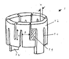
ここで、上記CZ法およびMCZ法で用いられる結晶製造用のヒーター7の形状は、図1に示すように円筒形状であり、主に等方性黒鉛でできている。現在主流である直流方式では、端子部7bを2本配し、その端子部7bでヒーター7を支える構造になっている。ヒーター7の発熱部7aはより効率的に発熱できるよう、スリット7cが数箇所から数十箇所刻まれている。尚、このヒーター7は、発熱部7aのうち、特に、上から延びるスリットの下端と下から延びるスリットの上端の間の部分である各発熱スリット部7dから主に発熱する。
【0009】
近年要求されている大口径結晶を低コストで製造する為には、必然的にルツボを大型化させなければならない。このルツボの大型化に伴い、ルツボ周辺の、ヒーター等の構造物のサイズも大型化している。ヒーターの大形化により、ヒーター自重、および、発熱時の分布の不均一性、さらには、MCZ法のように磁場を印加した操業の場合は磁場・電流の相互作用により、結晶製造での使用時にヒーター形状が変形することが問題となってきている。結晶製造での使用時にヒーター形状が変形することにより、ヒーターの発熱部と、結晶あるいは溶液との距離が変わり、熱の分布が変化することにより、原料融液内の温度が不均一となり、製造する結晶の単結晶化が阻害されたり、品質が不安定となる等の弊害が生じている。
【0010】
その対策として、ヒーターに2つの端子部以外にダミーの端子をつけ、それにより、3本以上の部分でヒーターを支える方法が一般的に行なわれている(例えば、特許文献1。)。ヒーターを端子部のみによって支える場合、2箇所で支えることとなり、端子のない部分は容易に変形してしまう。この変形は、ヒーター上部において、端子部のある部分では径が拡大し、端子の無い部分の径が縮小するように生じる。端子がない部分にダミーの端子を支えとして設置するこの方法は、このようなヒーターの変形を防ぐのにある程度効果のある方法であった。
【0011】
しかし、端子やダミーの端子を設けただけは、ヒーターがスリットにより分割されているため、完全に変形を防止することができず、特にヒーターの直径や高さが大きくなった場合は、変形を抑制することが困難である。また、ダミーの端子部分からの熱ロスや、さらには機械構造の複雑化等の問題がある。
【0012】
さらに、電流磁場を印加しながら大口径結晶を製造するMCZ法においては、変形の原因として、ヒーターの自重、熱膨張に加えて、ヒーター電流と磁場との相互作用で発生する電磁力がある。この電磁力は、かなりの強さで、たとえ、ヒーターを下端全体で支えたとしても、ヒーターの変形を防止することは困難である。
これに対して、MCZ法において、ヒーターを、スリットを入れた内側ヒーターと、スリットを入れた外側ヒーターの2重構造とし、それぞれに異なる方向の直流電流を流すことにより、ヒーター電流と磁場との相互作用で発生する電磁力を抑えて変形を防止する方法が提案されている(例えば、特許文献2。)。しかし、上記方法は、電磁力による変形を防ぐのには一定の効果があるものの、機械構造の複雑化により、著しいコストアップを招く上に、自重による変形がかえって大きくなってしまう等の問題があった。
【0013】
また、ヒーターの材質を等方性黒鉛から、より高強度で軽量な、例えばカーボンコンポジットのような材質に変更するという事が、試行されている。しかし、この方法では、発熱が不安定となること、ヒーター材料のコストアップを招くこと、さらには製造される結晶の純度が低下すること等の問題がある。
【0014】
【特許文献1】
特公平7−72116号公報
【特許文献2】
特開平9−208371号公報
【0015】
【発明が解決しようとする課題】
本発明はこのような問題点に鑑みてなされたもので、結晶製造での使用時に、ヒーターの発熱部の形状が変形することで原料融液内の温度が不均一となり、単結晶化が阻害され、結晶の品質が不安定となるのを防ぐことを、たとえ直径8インチ以上の大口径結晶を製造する場合であっても、安価で、しかも簡単かつ確実にできる結晶製造用ヒーター及び結晶製造装置並びに結晶製造方法を提供することを目的とする。
【0016】
【課題を解決するための手段】
本発明は、上記課題を解決するためになされたもので、本発明によれば、少なくとも、電流が供給される端子部と、抵抗加熱による発熱部とが設けられ、原料融液を収容するルツボを囲繞するように配置される、チョクラルスキー法により結晶を製造する場合に用いられるヒーターであって、該ヒーターは、結晶製造での使用時にヒーター形状が変形した後に、原料融液に対して均一の発熱分布を有するものであることを特徴とする結晶製造用ヒーターが提供される。
【0017】
このように、ヒーターが、結晶製造での使用時にヒーター形状が変形した後に、原料融液に対して均一の発熱分布を有するものであることで、変形後に、原料融液内の温度勾配を小さくできるため、結晶引き上げ中の有転位化を抑制でき、高品質の結晶を、安価で、しかも簡単かつ確実に得ることができる。
尚、ここで、原料融液に対して均一の発熱分布とは、ヒーターからの熱が、原料融液に向けて同心円状に放射していることを示している。
【0018】
また本発明によれば、少なくとも、電流が供給される端子部と、抵抗加熱による発熱部とが設けられ、原料融液を収容するルツボを囲繞するように配置される、チョクラルスキー法により結晶を製造する場合に用いられるヒーターであって、該ヒーターの発熱部の水平断面の形状が、楕円形状であり、結晶製造での使用時にヒーター形状が変形して、前記発熱部の水平断面形状が円形状となるものであることを特徴とする結晶製造用ヒーターが提供される。
【0019】
このように、ヒーターの発熱部の水平断面の形状が、楕円形状であり、結晶製造での使用時にヒーター形状が変形して、前記発熱部の水平断面形状が円形状となるものであることで、変形後に、原料融液に対する発熱分布を均一化することができる。そのため、結晶引き上げ中の有転位化を抑制でき、高品質の結晶を、安価で、しかも簡単かつ確実に得ることができる。
【0020】
この場合、前記発熱部の水平断面の楕円形状は、結晶製造での使用時のヒーター形状の変形により径が拡大する方向では予め径を小さくし、逆に、径が縮小する方向では予め径を大きくしたものであることが好ましい。また、前記発熱部の水平断面の楕円形状は、長径をD1とし短径をD2とした時、D1/D2の値が、1.01以上1.20以下の範囲であることが好ましい。
【0021】
このように、発熱部の水平断面の楕円形状は、結晶製造での使用時のヒーター形状の変形により径が拡大する方向では予め径を小さくし、逆に、径が縮小する方向では予め径を大きくしたものであることで、変形後の原料融液に対する発熱を、確実に均一化させることができる。また、ヒーターの加工性、コスト、強度の点から楕円形状の長径と短径の比は、1.01〜1.20の範囲とするのが良い。
【0022】
さらに本発明では、少なくとも、電流が供給される端子部と、抵抗加熱による発熱部とが設けられ、原料融液を収容するルツボを囲繞するように配置される、チョクラルスキー法により結晶を製造する場合に用いられるヒーターであって、該ヒーターの発熱部は、電気抵抗に分布をもたせたものであることを特徴とする結晶製造用ヒーターが提供される。
【0023】
このように、ヒーターの発熱部は、電気抵抗に分布をもたせたものであることで、変形後の原料融液に対する発熱を均一化することができる。そのため、結晶引き上げ中の有転位化を抑制でき、高品質の結晶を、安価で、しかも簡単かつ確実に得ることができる。
【0024】
この場合、前記発熱部の電気抵抗の分布は、結晶製造での使用時のヒーター形状の変形により、径が拡大する方向では予め電気抵抗を大きくし、逆に、径が縮小する方向では予め電気抵抗を小さく分布させたものであることが好ましい。
【0025】
このように、前記発熱部の電気抵抗の分布は、結晶製造での使用時のヒーター形状の変形により、径が拡大する方向では予め電気抵抗を大きくし、逆に、径が縮小する方向では予め電気抵抗を小さく分布させたものであることで、変形後の原料融液に対する発熱分布を、均一化させることができる。
【0026】
この場合、前記発熱部の電気抵抗の分布は、発熱スリット部の肉厚、発熱スリット部の幅、又は発熱スリット部の長さのいずれか一つ以上を変更することにより調整したものであることが好ましい。
【0027】
このように、発熱部の電気抵抗の分布は、発熱スリット部の肉厚、発熱スリット部の幅、又は発熱スリット部の長さのいずれか一つ以上を変更することにより、容易に調整することができる。
【0028】
また、前記発熱部の電気抵抗の分布は、結晶製造での使用時のヒーター形状の変形により径が拡大する方向での電気抵抗をR1とし、径が縮小する方向での電気抵抗をR2とした時、R1/R2の値が、1.01以上1.10以下の範囲で分布させたものであることが好ましい。
【0029】
このように、前記発熱部の電気抵抗の分布を、結晶製造での使用時のヒーター形状の変形により径が拡大する方向での電気抵抗をR1とし、径が縮小する方向での電気抵抗をR2とした時、R1/R2の値が、1.01以上1.10以下の範囲で分布させたものであることで、ヒーター加工上、ヒーター強度等において大きな問題を生じることなく変形後の原料融液に対する発熱を確実に均一化させることができる。
【0030】
さらに、本発明の結晶製造用ヒーターは、該ヒーターの発熱部水平断面の形状が楕円形状であり、結晶製造での使用時にヒーター形状が変形して、前記発熱部の水平断面の形状が円形状になるものであることに加えて、前記発熱部は、電気抵抗に分布をもたせたものであることができる。
【0031】
このように、ヒーターの発熱部水平断面の形状が楕円形状であり、結晶製造での使用時にヒーター形状が変形して、前記発熱部の水平断面の形状が円形状になるものであることに加えて、前記発熱部は、電気抵抗に分布をもたせたものであることで、変形後の原料融液に対する発熱をきめ細やかに微調整が可能となり、より確実に発熱分布を均一化させることができる。
【0032】
さらに、前記ヒーターが用いられるチョクラルスキー法は、MCZ法であることができる。
【0033】
このように、本発明の結晶製造用ヒーターは、MCZ法により結晶を製造するのに用いる場合に、特に有効である。MCZ法は特に大口径結晶の製造に用いられるし、電流と磁場の相互作用により、ヒーターがより変形し易いからである。
【0034】
さらに、前記製造する結晶は、シリコン単結晶であるものとすることができる。
【0035】
このように、本発明の結晶製造用ヒーターは、近年特に大口径化が著しくヒータも大型化しているシリコン単結晶を製造するヒーターに適用することができる。
【0036】
さらに本発明は、上記結晶製造用ヒーターを具備する結晶製造装置を提供し、また、その結晶製造装置を用いてチョクラルスキー法により結晶を製造する結晶製造方法を提供する。
【0037】
このような本発明の結晶製造用ヒーターを具備する結晶製造装置を用いて、チョクラルスキー法により結晶を製造すれば、高品質の結晶を、安価で、しかも簡単かつ確実に得ることができる。
【0038】
【発明の実施の形態】
以下、本発明の実施の形態について説明するが、本発明はこれらに限定されるものではない。
特に大口径結晶を製造するためにヒーターが大型化した現在においては、結晶製造での使用時に、ヒーターの形状が変形するのを完全に防止することは困難である。そのようなヒーター形状の変形を防止するための方法とし、ヒーターを分割するなどの方法が考えられるが、その場合、炉内構造の複雑化、ならびに炉内構造物のコストアップ等の問題が発生することが考えられる。さらに、磁場を印加したMCZ法においては、なおさらヒーター形状の変形防止は困難であり、結果として、原料融液内の温度不均一を防止することは困難であった。そこで、本発明者らは、ヒーターの変形を防止するのではなく、ヒーターは変形するものであるから、予めヒーター形状の変形を予想してヒーターを設計し、変形後に原料融液に対して均一の発熱分布を有するものとすれば、原料融液内の温度が不均一になることを防止できることに想到し、本発明を完成させたものである。
【0039】
すなわち、本発明では、結晶製造での使用時にヒーター形状が変形した時に、原料融液に対して均一の発熱分布を有するものとするため、以下に2つの方策を提案する。
【0040】
第1の方策は、ヒーター形状が結晶製造での使用時に変形するのを見越して、発熱部の水平断面の形状を、予め円形状にせずに、楕円形状とすることである。
【0041】
ここで、図3は、従来のヒーターの変形前(a)と変形後(b)の発熱部の水平断面の形状を示す概略図である。図3に示すように、従来の円形状の発熱部は、元々円形状であったものが使用時には変形して、端子部7b同士を結ぶ方向では変形後に径が拡大し、逆に、それぞれの端子部7bから90°離れた部分同士を結ぶ方向では変形後に径が縮小して、楕円形状になる。
【0042】
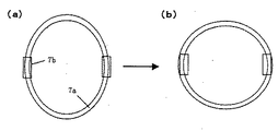
そこで、本発明では図2に示すように、ヒーター形状の変形により、径が拡大する方向では、予め径を小さくし、逆に変形して径が縮小する方向では予め径を大きくした楕円形状(a)としておく。このようにすることで、使用時に自重等で変形した時に、ヒーターの発熱部の水平断面の形状が円形状(b)となり、結果として、変形後に原料融液に対する発熱を均一化できる。
【0043】
一方、このようにヒーターの発熱部の水平断面の形状を楕円形状にする場合、ヒーター発熱部の上部と下部では、径が縮小する場所と径が拡大する場所が入れ替わる。したがって、上部と下部でも径を変えることが最も好ましい。しかし、そのようなヒーターは、発熱部の形状が複雑となり、製作が困難であるため、実際は発熱スリット部の変形を主に考慮して形状を決定するのが最も効率的である。
【0044】
尚、このようにヒーターの発熱部の水平断面の形状を楕円形状にする場合、長径をD1とし短径をD2とした時、D1/D2の値が、1.01以上1.20以下の範囲であることが好ましい。さらに、D1/D2の値が、1.03以上1.10以下の範囲であることがより好ましい。
1.01以上としなければ、ほとんどヒーター変形部を相殺する効果が望めない。また、1.20を超えて楕円形状とすると、加工コストが高く付くし、ヒーターの強度上も、この値以下とした方が望ましい。
【0045】
第2の方策は、ヒーター形状が、結晶製造での使用時に変形するのを見越して、予め発熱部の電気抵抗に分布をもたせることである。この時、ヒーター形状の変形により、径が拡大する方向では予め発熱部の電気抵抗を大きくし、変形して径が縮小する方向では予め発熱部の電気抵抗を小さくしたものとする。このようにすることで、変形した時に、原料融液からより遠い部分の発熱が大きく、原料融液からより近い部分の発熱が小さくなり、結果として、変形後に原料融液に対する発熱を均一化できる。
【0046】
発熱部の電気抵抗の分布は、例えば、▲1▼発熱スリット部の肉厚(図1の符号α)を変更すること、▲2▼発熱スリット部の幅(図1の符号β)を変更すること、又は▲3▼発熱スリット部の長さ(図1の符号γ)を変更することのうちいずれか一つ以上を行うことによって調整することができる。
【0047】
尚、このように発熱部の電気抵抗に分布をもたせるものとした場合、結晶製造での使用時のヒーター形状の変形により径が拡大する方向での電気抵抗をR1とし、径が縮小する方向での電気抵抗をR2とした時、R1/R2の値が、1.01以上1.10以下の範囲で分布させたものであることが好ましい。さらに、R1/R2の値が、1.01以上1.05以下の範囲で分布させたものであることがより好ましい。
これは、R1/R2を1.01以上としなければ効果が少ないし、1.10を超えるように肉厚等を変更するとなると加工上難しいし、ヒーター強度も問題となり得るからである。
【0048】
一方、上記2つの方策を組み合わせたヒーターを用いることもできる。このようにすることで、原料融液に対する発熱を均一化させるための微調整が可能となる。すなわち、ヒーター発熱部の水平断面を楕円形状とするとともに、電気抵抗に分布を持たせる。こうすることによって、ヒーターのどのような変形に対しても対応することができ、きめ細やかに温度分布を均一に調整できる。また、加工するヒーター形状の変形の度合いを小さくすることができ、ヒーター強度上も好ましい結果となった。
【0049】
上記したような本発明の結晶製造用ヒーターは、MCZ法により結晶を製造するのに用いる場合に、特に有効である。また、本発明の結晶製造用ヒーターは、シリコン単結晶を製造するのに用いることができる。
本発明のヒータをMCZ法で用いるのは、MCZ法は特に大口径結晶の製造に用いられるし、電流と磁場の相互作用により、ヒーターがより変形し易いからである。また、シリコン単結晶を製造するのに用いるのは、シリコン単結晶は近年特に大口径化が著しく、その製造のためにヒーターも大型化しているためである。
【0050】
さらに本発明は、上記結晶製造用ヒーターを具備する結晶製造装置を提供し、また、その結晶製造装置を用いてチョクラルスキー法により結晶を製造する結晶製造方法を提供する。本発明は、上記のような特性を有するヒーターを従来の炉内構造を有する結晶製造装置にセットするだけで、単結晶化率を大幅に改善することができ、既存の装置の設計変更等が不要であり、非常に簡単かつ安価に構成できる。
【0051】
本発明により提供される結晶製造用ヒーターを用いた場合、その発熱部の形状が結晶製造での使用時に変形した後に、原料融液に対して均一の発熱分布を有するものであることで、単結晶製造において、結晶の無転位化率を向上し、高品質な結晶を安定して製造することができる。しかも、炉内構造を複雑なものとせず、また比較的安価で、かつ確実に、原料融液に対する発熱分布の均一化を達成できる。
【0052】
【実施例】
以下、実施例を示し、本発明を具体的に説明するが、本発明は下記の実施例に限定されるものではない。
(実施例1)
横方向の磁場を印加したMCZ法によりシリコン単結晶を製造した。直径32インチ(800mm)のルツボに、原料シリコン300kgをチャージし、直径12インチ(305mm)のシリコン単結晶を引き上げた。この時、ヒーターの発熱部の形状が、長径D1が925mmで、短径D2(端子側)が915mmの楕円形状であり(D1/D2=1.01)、電気抵抗が発熱部内で均一であるヒーターを用いた。このヒーターを用いて結晶を製造したところ、特に問題無く最後まで結晶の成長を行なうことができた。
尚、この条件で20回シリコン単結晶を引き上げた時の無転位化率を表1に示す。
【0053】
(実施例2)
実施例1と同様に、横方向の磁場を印加したMCZ法によりシリコン単結晶を製造した。直径32インチ(800mm)のルツボに、原料シリコン300kgをチャージし、直径12インチ(305mm)のシリコン単結晶を引き上げた。この時、ヒーターの発熱部の形状が、直径920mmの円形状であり、結晶製造での使用時のヒーター形状の変形により、径が拡大して長径となる方向(端子側)の発熱スリット部の電気抵抗をR1とし、径が縮小して短径となる方向の発熱スリット部の電気抵抗をR2としたとき、R1/R2=1.10であるヒーターを使用した。発熱スリット部の電気抵抗は、短径となる部分の発熱スリット部の肉厚を33mmとし、長径となる部分の発熱スリット部の肉厚を30mmとすることで分布をもたせた。このヒーターを用いて結晶を製造したところ、特に問題無く最後まで結晶の成長を行なうことができた。
尚、この条件で20回シリコン単結晶を引き上げた時の無転位化率を表1に示す。
【0054】
(比較例1)
実施例1と同様に、横方向の磁場を印加したMCZ法によりシリコン単結晶を製造した。直径32インチ(800mm)のルツボに、原料シリコン300kgをチャージし、直径12インチ(305mm)のシリコン単結晶を引き上げた。この時、ヒーターの発熱部の形状は、直径920mmの円形状であり(D1/D2=1.00)、電気抵抗が発熱部内で均一である(R1/R2=1.00)ヒーターを用いた。しかし、このヒーターは、常温で結晶製造装置内に装着された段階で、自重により、長径が930mmで、短径が910mmの楕円形状に変形していることが確認された。このヒーターを用いて結晶をある程度製造したところ、発熱部が長径となった方向で原料融液表面に固化が観測され、結晶製造を中断せざるを得ない場合があった。
尚、この条件で20回シリコン単結晶を引き上げた時の無転位化率を表1に示す。
【0055】
【表1】

表1から明らかなように、育成結晶の無転位化率は、比較例1のヒーターを用いて結晶を育成したときに比べて、実施例1及び実施例2のヒーターを用いて結晶を育成したときの方が高く、大幅に改善できていることがわかる。
【0057】
尚、本発明は、上記実施形態に限定されるものではない。上記実施形態は、例示であり、本発明の特許請求の範囲に記載された技術的思想と実質的に同一な構成を有し、同様な作用効果を奏するものは、いかなるものであっても本発明の技術的範囲に包含される。
【0058】
例えば、本発明の実施例では、主にシリコン単結晶の引き上げ時に磁場を印加するMCZ法について説明したが、本発明はこれに限定されず、磁場を印加しない通常のCZ法にも適用できる。
また、引き上げる結晶もシリコンに限定されるものではなく、化合物半導体や酸化物単結晶等の成長にも適用できることは言うまでもない。
【0059】
【発明の効果】
以上説明したように、本発明によれば、CZ法により結晶を製造する場合に用いられるヒーターが、発熱部の形状が結晶製造での使用時に変形した後に、原料融液に対して均一の発熱分布を有するものであることで、単結晶製造において、結晶の無転位化率を向上し、高品質な結晶を安定して製造することを、安価で、しかも簡単かつ確実に達成できる。
【図面の簡単な説明】
【図1】結晶製造用ヒーターを示す概略斜視図である。
【図2】本発明の楕円形状である結晶製造用ヒーターの、変形前と変形後の発熱部の水平断面の形状を示す概略図である。(a)変形前、(b)変形後。
【図3】従来の円形状である結晶製造用ヒーターの、変形前と変形後の発熱部の水平断面の形状を示す概略図である。(a)変形前、(b)変形後。
【図4】CZ法による結晶製造装置を示す概略図である。
【符号の説明】
1…種ホルダー、 2…種結晶、 3…絞り部、 4…結晶、 5…ルツボ、6…原料融液、 7…ヒーター、 7a…発熱部、 7b…端子部、 7c…スリット、 7d…発熱スリット部、 8…断熱部材、 9…シャフト、 10…ワイヤー、 11…メインチャンバ−、 12…引き上げチャンバー α…発熱スリット部の肉厚、 β…発熱スリット部の幅、 γ…発熱スリット部の長さ。[0001]
BACKGROUND OF THE INVENTION
The present invention relates to a crystal manufacturing heater used when growing a crystal by the Czochralski method, a crystal manufacturing apparatus using the same, and a crystal manufacturing method. In particular, a large diameter crystal having a diameter of 8 inches or more is applied with a magnetic field. The present invention relates to a crystal manufacturing heater suitable for manufacturing, a crystal manufacturing apparatus using the same, and a crystal manufacturing method.
[0002]
[Prior art]
A crystal used as a substrate of a semiconductor device is, for example, a silicon single crystal, and is mainly manufactured by a Czochralski method (hereinafter abbreviated as CZ method).
[0003]
When a crystal is manufactured by the CZ method, for example, it is manufactured using a crystal manufacturing apparatus as shown in FIG. The crystal manufacturing apparatus includes a member for melting a raw material polycrystal such as silicon, a mechanism for pulling up single crystal silicon, and the like, which are accommodated in the main chamber 11. A pulling chamber 12 extending upward from the ceiling of the main chamber 11 is connected, and a mechanism (not shown) for pulling up the crystal 4 with a
[0004]
A crucible 5 that accommodates the melted
[0005]
A
[0006]
The raw material lump is accommodated in the crucible 5 arranged in such a crystal manufacturing apparatus, and the crucible 5 is heated by the
[0007]
Recently, a so-called MCZ method (Magnetic field applied Czochralski Method), which is an improvement of the CZ method, is also known. In this MCZ method, a magnetic field is applied to the raw material melt to suppress the thermal convection of the raw material melt and produce a crystal. In recent years, a silicon single crystal having a large diameter of 8 inches or more is required. When manufacturing a silicon single crystal having such a large diameter, the MCZ method can suppress the thermal convection of the raw material melt. It is effective to use.
[0008]
Here, the
[0009]
In order to produce large-diameter crystals that have been required in recent years at low cost, the crucible must be enlarged.ThisI must. With the increase in size of the crucible, the size of structures such as heaters around the crucible is also increased. Due to the larger size of the heater, the heater's own weight and non-uniform distribution during heat generation, and in the case of an operation with a magnetic field applied like the MCZ method, it can be used for crystal production due to the interaction between magnetic field and current. Sometimes the heater shape is deformed. When the shape of the heater is deformed during use in crystal production, the distance between the heat generating part of the heater and the crystal or solution changes, and the heat distribution changes, resulting in nonuniform temperature in the raw material melt. There are problems such as hindering the single crystallization of the crystals and making the quality unstable.
[0010]
As a countermeasure, a method is generally used in which a dummy terminal is attached to the heater in addition to the two terminal portions, thereby supporting the heater at three or more portions (for example, Patent Document 1). When the heater is supported only by the terminal portion, the heater is supported at two locations, and the portion without the terminal is easily deformed. This deformation occurs in the upper part of the heater such that the diameter is increased at a portion where the terminal portion is present and the diameter is decreased at a portion where the terminal is not present. This method of installing a dummy terminal as a support in a portion where there is no terminal has been effective to some extent in preventing such deformation of the heater.
[0011]
However, simply providing a terminal or dummy terminal does not completely prevent deformation because the heater is divided by slits, especially when the heater diameter or height increases. It is difficult to suppress. Further, there are problems such as heat loss from the dummy terminal portion and further complication of the mechanical structure.
[0012]
Furthermore, in the MCZ method in which a large-diameter crystal is produced while applying a current magnetic field, the cause of deformation is an electromagnetic force generated by the interaction between the heater current and the magnetic field in addition to the heater's own weight and thermal expansion. This electromagnetic force is quite strong, and even if the heater is supported by the entire lower end, it is difficult to prevent the heater from being deformed.
On the other hand, in the MCZ method, the heater has a double structure of an inner heater with a slit and an outer heater with a slit. A method for preventing deformation by suppressing electromagnetic force generated by interaction has been proposed (for example, Patent Document 2). However, although the above method has a certain effect in preventing deformation due to electromagnetic force, there is a problem that, due to the complexity of the mechanical structure, the cost increases significantly, and deformation due to its own weight increases. there were.
[0013]
Attempts have also been made to change the material of the heater from isotropic graphite to a material that is stronger and lighter, such as carbon composite. However, this method has problems such as unstable heat generation, an increase in the cost of the heater material, and a decrease in the purity of the produced crystal.
[0014]
[Patent Document 1]
Japanese Patent Publication No. 7-72116
[Patent Document 2]
JP-A-9-208371
[0015]
[Problems to be solved by the invention]
The present invention has been made in view of such problems, and when used in crystal production, the shape of the heat generating portion of the heater is deformed, so that the temperature in the raw material melt becomes non-uniform and single crystallization is hindered. In order to prevent the quality of the crystal from becoming unstable, even in the case of manufacturing a large-diameter crystal having a diameter of 8 inches or more, the crystal manufacturing heater and the crystal manufacturing can be easily and reliably performed at low cost. An object is to provide an apparatus and a crystal manufacturing method.
[0016]
[Means for Solving the Problems]
The present invention has been made to solve the above-described problems. According to the present invention, at least a terminal portion to which a current is supplied and a heat generating portion by resistance heating are provided, and a crucible for containing a raw material melt is provided. The heater is used to produce a crystal by the Czochralski method and is arranged so as to surround the heater after the shape of the heater is deformed when used in crystal production. Provided is a heater for producing a crystal, characterized by having a uniform heat generation distribution..
[0017]
As described above, the heater has a uniform heat generation distribution with respect to the raw material melt after the shape of the heater is deformed during use in crystal production, so that the temperature gradient in the raw material melt is reduced after the deformation. Therefore, dislocation formation during crystal pulling can be suppressed, and high-quality crystals can be obtained inexpensively and easily and reliably.
Here, the uniform heat generation distribution with respect to the raw material melt indicates that heat from the heater radiates concentrically toward the raw material melt.
[0018]
Further, according to the present invention, at least a terminal portion to which a current is supplied and a heat generating portion by resistance heating are provided, and the crystal is formed by the Czochralski method, which is disposed so as to surround the crucible containing the raw material melt. The shape of the horizontal cross section of the heat generating part of the heater is elliptical, and the shape of the heater is deformed when used in crystal production, so that the horizontal cross sectional shape of the heat generating part is Provided is a crystal manufacturing heater characterized by being circular..
[0019]
Thus, the shape of the horizontal cross section of the heat generating portion of the heater is an elliptical shape, the heater shape is deformed when used in crystal production, and the horizontal cross sectional shape of the heat generating portion is circular. After the deformation, the heat distribution with respect to the raw material melt can be made uniform. Therefore, dislocation formation during crystal pulling can be suppressed, and high-quality crystals can be obtained inexpensively and easily and reliably.
[0020]
In this case, the elliptical shape of the horizontal cross section of the heat generating portion is reduced in advance in the direction in which the diameter increases due to deformation of the heater shape during use in crystal manufacture, and conversely in the direction in which the diameter decreases, the diameter is increased in advance. Preferably larger.In addition, in the elliptical shape of the horizontal section of the heat generating portion, it is preferable that the value of D1 / D2 is in the range of 1.01 to 1.20 when the major axis is D1 and the minor axis is D2..
[0021]
As described above, the elliptical shape of the horizontal cross section of the heat generating portion is reduced in advance in the direction in which the diameter increases due to deformation of the heater shape during use in crystal production, and conversely, in the direction in which the diameter decreases, the diameter is increased in advance. By making it large, the heat generation with respect to the raw material melt after deformation can be surely made uniform. The ratio of the major axis to the minor axis of the elliptical shape is preferably in the range of 1.01 to 1.20 from the viewpoint of workability, cost, and strength of the heater.
[0022]
Furthermore, in the present invention, at least a terminal portion to which current is supplied and a heat generating portion by resistance heating are provided, and the crystal is manufactured by the Czochralski method, which is arranged so as to surround the crucible containing the raw material melt. There is provided a heater for manufacturing a crystal, wherein a heating part of the heater has a distribution of electric resistance..
[0023]
Thus, the heat generation part of the heater has a distribution of electric resistance, so that the heat generation with respect to the raw material melt after deformation can be made uniform. Therefore, dislocation formation during crystal pulling can be suppressed, and high-quality crystals can be obtained inexpensively and easily and reliably.
[0024]
In this case, the distribution of the electric resistance of the heat generating portion is preliminarily increased in the direction in which the diameter increases due to deformation of the heater shape during use in crystal production, and conversely in the direction in which the diameter decreases. It is preferable that the resistance is distributed small..
[0025]
As described above, the distribution of the electric resistance of the heat generating portion is preliminarily increased in the direction in which the diameter increases due to deformation of the heater shape during use in crystal production, and conversely in the direction in which the diameter decreases. By distributing the electrical resistance to be small, the heat generation distribution with respect to the raw material melt after deformation can be made uniform.
[0026]
In this case, the electrical resistance distribution of the heat generating part is adjusted by changing one or more of the thickness of the heat generating slit part, the width of the heat generating slit part, or the length of the heat generating slit part. Is preferred.
[0027]
Thus, the electrical resistance distribution of the heat generating part can be easily adjusted by changing one or more of the thickness of the heat generating slit part, the width of the heat generating slit part, or the length of the heat generating slit part. Can do.
[0028]
In addition, regarding the distribution of the electric resistance of the heat generating portion, the electric resistance in the direction in which the diameter increases due to the deformation of the heater shape during use in crystal production is R1, and the electric resistance in the direction in which the diameter decreases is R2. In this case, the value of R1 / R2 is preferably distributed in the range of 1.01 to 1.10..
[0029]
As described above, regarding the distribution of the electric resistance of the heat generating portion, the electric resistance in the direction in which the diameter increases due to the deformation of the heater shape during use in crystal production is R1, and the electric resistance in the direction in which the diameter decreases is R2. When the value of R1 / R2 is distributed in the range of 1.01 or more and 1.10 or less, the raw material melt after deformation does not cause a big problem in heater processing, etc. Heat generation with respect to the liquid can be made uniform.
[0030]
Furthermore, in the heater for crystal production of the present invention, the shape of the horizontal section of the heat generating portion of the heater is elliptical, the shape of the heater deforms when used in crystal manufacture, and the shape of the horizontal cross section of the heat generating portion is circular. In addition, the heat generating part may have a distribution of electric resistance..
[0031]
As described above, the shape of the horizontal cross section of the heat generating portion is elliptical, the shape of the heater is deformed when used in crystal production, and the shape of the horizontal cross section of the heat generating portion is circular. In addition, since the heat generating portion has a distribution of electric resistance, it is possible to finely adjust the heat generation with respect to the raw material melt after deformation, and to more uniformly make the heat generation distribution more reliable. .
[0032]
Further, the Czochralski method in which the heater is used can be an MCZ method..
[0033]
Thus, the heater for producing a crystal of the present invention is particularly effective when used for producing a crystal by the MCZ method. This is because the MCZ method is particularly used for manufacturing large-diameter crystals, and the heater is more easily deformed by the interaction between the current and the magnetic field.
[0034]
Further, the crystal to be manufactured may be a silicon single crystal..
[0035]
As described above, the crystal manufacturing heater of the present invention can be applied to a heater for manufacturing a silicon single crystal whose diameter has been remarkably increased in recent years and whose heater is also increased in size.
[0036]
Furthermore, the present invention provides a crystal production apparatus comprising the above-described crystal production heater.,Also provided is a crystal manufacturing method for manufacturing crystals by the Czochralski method using the crystal manufacturing apparatus..
[0037]
If a crystal is produced by the Czochralski method using such a crystal production apparatus having the crystal production heater of the present invention, a high-quality crystal can be obtained inexpensively, easily and reliably.
[0038]
DETAILED DESCRIPTION OF THE INVENTION
Hereinafter, although embodiment of this invention is described, this invention is not limited to these.
In particular, at the present time when the heater is enlarged in order to produce a large-diameter crystal, it is difficult to completely prevent the shape of the heater from being deformed when used in crystal production. As a method for preventing such deformation of the heater shape, a method such as dividing the heater can be considered, but in that case, problems such as complication of the internal structure of the furnace and an increase in the cost of the internal structure occur. It is possible to do. Further, in the MCZ method in which a magnetic field is applied, it is difficult to prevent the heater shape from being deformed, and as a result, it is difficult to prevent temperature unevenness in the raw material melt. Therefore, the present inventors do not prevent the deformation of the heater, but the heater is deformed. Therefore, the heater is designed in advance by predicting the deformation of the heater shape, and is uniform with respect to the raw material melt after the deformation. Thus, the present invention has been completed by conceiving that the temperature in the raw material melt can be prevented from becoming non-uniform.
[0039]
That is, the present invention proposes the following two measures in order to have a uniform heat generation distribution with respect to the raw material melt when the heater shape is deformed during use in crystal production.
[0040]
The first strategy is to make the shape of the horizontal cross section of the heat generating portion into an elliptical shape instead of a circular shape in advance in anticipation of the heater shape being deformed during use in crystal production.
[0041]
Here, FIG. 3 is a schematic diagram showing the shape of the horizontal section of the heat generating part before (a) and after (b) deformation of the conventional heater. As shown in FIG. 3, the conventional circular heat generating portion is originally circular in shape but deforms when used, and in the direction connecting the terminal portions 7 b, the diameter increases after deformation, and conversely, In the direction connecting the portions separated by 90 ° from the terminal portion 7b, the diameter is reduced after the deformation, and becomes an elliptical shape.
[0042]
Therefore, in the present invention, as shown in FIG. 2, due to the deformation of the heater shape, an elliptical shape in which the diameter is reduced in advance in the direction in which the diameter is increased, and is increased in advance in the direction in which the diameter is reduced by deformation. It is set as a). In this way, when the heater is deformed by its own weight or the like during use, the shape of the horizontal section of the heat generating portion of the heater becomes circular (b), and as a result, the heat generation with respect to the raw material melt can be made uniform after the deformation.
[0043]
On the other hand, when the shape of the horizontal cross section of the heat generating part of the heater is made elliptical in this way, the place where the diameter is reduced and the place where the diameter is enlarged are switched between the upper part and the lower part of the heater heat generating part. Therefore, it is most preferable to change the diameter between the upper part and the lower part. However, in such a heater, since the shape of the heat generating part is complicated and difficult to manufacture, in practice, it is most efficient to determine the shape mainly considering the deformation of the heat generating slit part.
[0044]
In addition, when the shape of the horizontal cross section of the heat generating part of the heater is elliptical in this way, the value of D1 / D2 is in the range of 1.01 to 1.20 when the major axis is D1 and the minor axis is D2. It is preferable that Furthermore, it is more preferable that the value of D1 / D2 is in the range of 1.03 to 1.10.
Unless it is set to 1.01 or more, the effect of offsetting the heater deformation portion is hardly expected. Further, if the elliptical shape exceeds 1.20, the processing cost is high, and the strength of the heater is preferably set to this value or less.
[0045]
The second measure is to have a distribution in the electrical resistance of the heat generating portion in advance in anticipation of the heater shape being deformed during use in crystal production. At this time, it is assumed that the electric resistance of the heat generating portion is increased in advance in the direction in which the diameter increases due to the deformation of the heater shape, and the electric resistance of the heat generating portion is decreased in advance in the direction in which the diameter decreases due to deformation. In this way, when deformed, the heat generation in the portion farther from the raw material melt is larger and the heat generation in the portion closer to the raw material melt is smaller, and as a result, the heat generation with respect to the raw material melt can be made uniform after deformation. .
[0046]
The distribution of the electrical resistance of the heat generating part is, for example, (1) changing the thickness of the heat generating slit (symbol α in FIG. 1), and (2) changing the width of the heat generating slit (symbol β in FIG. 1). It can be adjusted by performing any one or more of (3) changing the length of the heat generating slit (symbol γ in FIG. 1).
[0047]
When the distribution of the electrical resistance of the heat generating part is given in this way, the electrical resistance in the direction in which the diameter increases due to the deformation of the heater shape during use in crystal production is R1, and in the direction in which the diameter decreases. When the electrical resistance of R2 is R2, it is preferable that the value of R1 / R2 is distributed in the range of 1.01 to 1.10. further,R1 / R2Is more preferably distributed in the range of 1.01 to 1.05.
this is,R1 / R2If the thickness is not more than 1.01, the effect is small, and if the thickness is changed so as to exceed 1.10, it is difficult to process, and the heater strength may also be a problem.
[0048]
On the other hand, a heater combining the above two measures can be used. By doing in this way, the fine adjustment for making the heat_generation | fever with respect to a raw material melt uniform can be performed. That is, the horizontal cross section of the heater heating part is oval.ConditionIn addition, the electric resistance is distributed. In this way, any deformation of the heater can be dealt with, and the temperature distribution can be finely adjusted uniformly. In addition, the degree of deformation of the heater shape to be processed can be reduced, and the heater strength is also favorable.
[0049]
The crystal production heater of the present invention as described above is particularly effective when used for producing crystals by the MCZ method. The crystal manufacturing heater of the present invention can be used for manufacturing a silicon single crystal.
The reason why the heater of the present invention is used in the MCZ method is that the MCZ method is used particularly for the production of large-diameter crystals, and the heater is more easily deformed by the interaction between the current and the magnetic field. Also, the reason why silicon single crystals are used is that silicon single crystals have been particularly large in diameter in recent years, and heaters have also become larger for their manufacture.
[0050]
Furthermore, the present invention provides a crystal production apparatus comprising the above-described crystal production heater, and also provides a crystal production method for producing crystals by the Czochralski method using the crystal production apparatus. The present invention can greatly improve the single crystallization rate simply by setting a heater having the above-described characteristics in a crystal manufacturing apparatus having a conventional in-furnace structure, and can change the design of an existing apparatus. It is unnecessary and can be configured very easily and inexpensively.
[0051]
When the crystal manufacturing heater provided by the present invention is used, the shape of the heat generating part is deformed during use in crystal manufacturing, and then has a uniform heat generation distribution with respect to the raw material melt. In crystal production, the dislocation-free rate of crystals can be improved, and high-quality crystals can be produced stably. In addition, the furnace structure is not complicated, and the heat generation distribution relative to the raw material melt can be made uniform relatively reliably and inexpensively.
[0052]
【Example】
EXAMPLES Hereinafter, although an Example is shown and this invention is demonstrated concretely, this invention is not limited to the following Example.
Example 1
A silicon single crystal was manufactured by the MCZ method in which a transverse magnetic field was applied. A crucible having a diameter of 32 inches (800 mm) was charged with 300 kg of raw material silicon, and a silicon single crystal having a diameter of 12 inches (305 mm) was pulled up. At this time, the shape of the heat generating part of the heater is an elliptical shape having a major axis D1 of 925 mm and a minor axis D2 (terminal side) of 915 mm (D1 / D2 = 1.01), and the electric resistance is uniform in the heat generating part. A heater was used. When crystals were produced using this heater, the crystals could be grown to the end without any particular problems.
Table 1 shows the dislocation-free rate when the silicon single crystal is pulled 20 times under these conditions.
[0053]
(Example 2)
Similarly to Example 1, a silicon single crystal was manufactured by the MCZ method in which a lateral magnetic field was applied. A crucible having a diameter of 32 inches (800 mm) was charged with 300 kg of raw material silicon, and a silicon single crystal having a diameter of 12 inches (305 mm) was pulled up. At this time, the shape of the heat generating portion of the heater is a circular shape with a diameter of 920 mm, and due to the deformation of the heater shape when used in crystal production, the diameter of the heat generating slit portion in the direction (terminal side) increases in diameter to become the long diameter. A heater with R1 / R2 = 1.10 was used, where R1 is the electric resistance of the heat generating slit portion in the direction in which the diameter is reduced and the minor diameter is reduced to the short diameter. The electric resistance of the heat generating slit portion was distributed by setting the thickness of the heat generating slit portion at the short diameter portion to 33 mm and the wall thickness of the heat generating slit portion at the long diameter portion to 30 mm. When crystals were produced using this heater, the crystals could be grown to the end without any particular problems.
Table 1 shows the dislocation-free rate when the silicon single crystal is pulled 20 times under these conditions.
[0054]
(Comparative Example 1)
Similarly to Example 1, a silicon single crystal was manufactured by the MCZ method in which a lateral magnetic field was applied. A crucible having a diameter of 32 inches (800 mm) was charged with 300 kg of raw material silicon, and a silicon single crystal having a diameter of 12 inches (305 mm) was pulled up. At this time, the shape of the heat generating portion of the heater was a circular shape having a diameter of 920 mm (D1 / D2 = 1.00), and the electric resistance was uniform in the heat generating portion (R1 / R2 = 1.00). . However, it was confirmed that this heater was deformed into an elliptical shape having a major axis of 930 mm and a minor axis of 910 mm due to its own weight when it was mounted in the crystal manufacturing apparatus at room temperature. When crystals were produced to some extent using this heater, solidification was observed on the surface of the raw material melt in the direction in which the heat generating part had a long diameter, and the production of the crystals had to be interrupted.
Table 1 shows the dislocation-free rate when the silicon single crystal is pulled 20 times under these conditions.
[0055]
[Table 1]
As is clear from Table 1, the dislocation-free rate of the grown crystal was grown using the heaters of Example 1 and Example 2 compared to when the crystal was grown using the heater of Comparative Example 1. The time is higher and it can be seen that it has improved significantly.
[0057]
The present invention is not limited to the above embodiment. The above-described embodiment is an exemplification, and the present invention has substantially the same configuration as the technical idea described in the claims of the present invention, and any device that exhibits the same function and effect is the present invention. It is included in the technical scope of the invention.
[0058]
For example, in the embodiments of the present invention, the MCZ method in which a magnetic field is applied mainly when pulling up a silicon single crystal has been described. However, the present invention is not limited to this, and can be applied to a normal CZ method in which a magnetic field is not applied.
Needless to say, the crystal to be pulled is not limited to silicon, and can be applied to the growth of compound semiconductors, oxide single crystals, and the like.
[0059]
【The invention's effect】
As described above, according to the present invention, the heater used in the case of producing a crystal by the CZ method has a uniform heat generation with respect to the raw material melt after the shape of the heat generating portion is deformed during use in crystal production. By having the distribution, it is possible to achieve a low-cost, simple and reliable production of a single crystal with improved dislocation-free rate of crystals and stable production of high-quality crystals.
[Brief description of the drawings]
FIG. 1 is a schematic perspective view showing a heater for crystal production.
FIG. 2 is a schematic view showing the shape of a horizontal cross section of a heat generating part before and after deformation of the elliptical heater for crystal production according to the present invention. (A) Before deformation, (b) After deformation.
FIG. 3 is a schematic diagram showing the shape of a horizontal section of a heat generating part before and after deformation of a conventional circular crystal manufacturing heater. (A) Before deformation, (b) After deformation.
FIG. 4 is a schematic view showing an apparatus for producing a crystal by the CZ method.
[Explanation of symbols]
DESCRIPTION OF
Claims (13)
Priority Applications (5)
| Application Number | Priority Date | Filing Date | Title |
|---|---|---|---|
| JP2002267600A JP4161655B2 (en) | 2002-09-13 | 2002-09-13 | Crystal manufacturing heater, crystal manufacturing apparatus, and crystal manufacturing method |
| PCT/JP2003/011444 WO2004024998A1 (en) | 2002-09-13 | 2003-09-08 | Heater for crystal formation, apparatus for forming crystal and method for forming crystal |
| EP03795314A EP1538242B8 (en) | 2002-09-13 | 2003-09-08 | Heater for manufacturing a crystal, crystal manufacturing apparatus and crystal manufacturing method. |
| US10/503,721 US7201801B2 (en) | 2002-09-13 | 2003-09-08 | Heater for manufacturing a crystal |
| KR1020047012641A KR101014600B1 (en) | 2002-09-13 | 2003-09-08 | Heater for crystal formation, apparatus for forming crystal and method for forming crystal |
Applications Claiming Priority (1)
| Application Number | Priority Date | Filing Date | Title |
|---|---|---|---|
| JP2002267600A JP4161655B2 (en) | 2002-09-13 | 2002-09-13 | Crystal manufacturing heater, crystal manufacturing apparatus, and crystal manufacturing method |
Publications (3)
| Publication Number | Publication Date |
|---|---|
| JP2004099416A JP2004099416A (en) | 2004-04-02 |
| JP2004099416A5 JP2004099416A5 (en) | 2005-05-26 |
| JP4161655B2 true JP4161655B2 (en) | 2008-10-08 |
Family
ID=31986709
Family Applications (1)
| Application Number | Title | Priority Date | Filing Date |
|---|---|---|---|
| JP2002267600A Expired - Fee Related JP4161655B2 (en) | 2002-09-13 | 2002-09-13 | Crystal manufacturing heater, crystal manufacturing apparatus, and crystal manufacturing method |
Country Status (5)
| Country | Link |
|---|---|
| US (1) | US7201801B2 (en) |
| EP (1) | EP1538242B8 (en) |
| JP (1) | JP4161655B2 (en) |
| KR (1) | KR101014600B1 (en) |
| WO (1) | WO2004024998A1 (en) |
Families Citing this family (10)
| Publication number | Priority date | Publication date | Assignee | Title |
|---|---|---|---|---|
| JP4807033B2 (en) * | 2005-10-17 | 2011-11-02 | 日本精工株式会社 | Half toroidal continuously variable transmission |
| JP4919343B2 (en) * | 2007-02-06 | 2012-04-18 | コバレントマテリアル株式会社 | Single crystal pulling device |
| JP2011093778A (en) * | 2009-09-29 | 2011-05-12 | Shin Etsu Handotai Co Ltd | Silicon single crystal wafer and method for producing silicon single crystal |
| JP2012051775A (en) * | 2010-09-03 | 2012-03-15 | Hitachi Cable Ltd | Heating element, and crystal growth device and gas phase growth device using the same |
| DE102011079284B3 (en) | 2011-07-15 | 2012-11-29 | Siltronic Ag | Annular resistance heater for supplying heat to a growing single crystal |
| JP2013220954A (en) * | 2012-04-13 | 2013-10-28 | Ibiden Co Ltd | Graphite heater |
| WO2014175120A1 (en) * | 2013-04-24 | 2014-10-30 | Sumco Techxiv株式会社 | Method for producing single crystal, and method for producing silicon wafer |
| JP6459406B2 (en) * | 2014-11-04 | 2019-01-30 | 住友電気工業株式会社 | Silicon carbide single crystal manufacturing apparatus and silicon carbide single crystal manufacturing method |
| KR101885210B1 (en) | 2016-11-30 | 2018-09-11 | 웅진에너지 주식회사 | Heating unit and Apparatus for growing a ingot including the unit |
| CN107460539B (en) * | 2017-06-30 | 2018-10-19 | 内蒙古中环光伏材料有限公司 | A kind of monocrystalline silicon production method |
Family Cites Families (13)
| Publication number | Priority date | Publication date | Assignee | Title |
|---|---|---|---|---|
| JPH02172885A (en) | 1988-12-26 | 1990-07-04 | Nkk Corp | Production of silicon single crystal |
| JP3401059B2 (en) | 1993-09-06 | 2003-04-28 | 松下電器産業株式会社 | Electrochemical gas sensor |
| JPH09208371A (en) | 1996-02-02 | 1997-08-12 | Sumitomo Sitix Corp | Heater for apparatus for pulling up single crystal |
| JPH09227286A (en) * | 1996-02-24 | 1997-09-02 | Komatsu Electron Metals Co Ltd | Apparatus for single crystal |
| JP2956575B2 (en) | 1996-03-01 | 1999-10-04 | 住友金属工業株式会社 | Resistance heating element for growing single crystals |
| JPH09263491A (en) * | 1996-03-27 | 1997-10-07 | Shin Etsu Handotai Co Ltd | Device for producing silicon single crystal |
| JPH10167876A (en) | 1996-11-29 | 1998-06-23 | Super Silicon Kenkyusho:Kk | Device for producing crystal by cz method |
| JP3587235B2 (en) | 1997-11-05 | 2004-11-10 | 三菱住友シリコン株式会社 | Carbon heater for single crystal growing equipment |
| JPH11139895A (en) | 1997-11-11 | 1999-05-25 | Komatsu Electron Metals Co Ltd | Heater for heating crucible of crystal pulling-up device |
| JP3444178B2 (en) * | 1998-02-13 | 2003-09-08 | 信越半導体株式会社 | Single crystal manufacturing method |
| US6093913A (en) * | 1998-06-05 | 2000-07-25 | Memc Electronic Materials, Inc | Electrical heater for crystal growth apparatus with upper sections producing increased heating power compared to lower sections |
| JP3788116B2 (en) | 1999-07-26 | 2006-06-21 | 株式会社Sumco | Multifunctional heater for single crystal growth and single crystal pulling device |
| US6285011B1 (en) * | 1999-10-12 | 2001-09-04 | Memc Electronic Materials, Inc. | Electrical resistance heater for crystal growing apparatus |
-
2002
- 2002-09-13 JP JP2002267600A patent/JP4161655B2/en not_active Expired - Fee Related
-
2003
- 2003-09-08 US US10/503,721 patent/US7201801B2/en not_active Expired - Lifetime
- 2003-09-08 KR KR1020047012641A patent/KR101014600B1/en active IP Right Grant
- 2003-09-08 EP EP03795314A patent/EP1538242B8/en not_active Expired - Lifetime
- 2003-09-08 WO PCT/JP2003/011444 patent/WO2004024998A1/en active Application Filing
Also Published As
| Publication number | Publication date |
|---|---|
| US20050081779A1 (en) | 2005-04-21 |
| KR20050037434A (en) | 2005-04-21 |
| EP1538242B8 (en) | 2013-04-03 |
| JP2004099416A (en) | 2004-04-02 |
| EP1538242A4 (en) | 2009-07-29 |
| EP1538242A1 (en) | 2005-06-08 |
| EP1538242B1 (en) | 2012-08-08 |
| US7201801B2 (en) | 2007-04-10 |
| WO2004024998A1 (en) | 2004-03-25 |
| KR101014600B1 (en) | 2011-02-16 |
Similar Documents
| Publication | Publication Date | Title |
|---|---|---|
| KR101997565B1 (en) | Method for producing monocrystalline silicon | |
| US20070062442A1 (en) | Apparatus for growing high quality silicon single crystal ingot and growing method using the same | |
| US8268077B2 (en) | Upper heater, single crystal production apparatus, and method for producing single crystal | |
| JP4161655B2 (en) | Crystal manufacturing heater, crystal manufacturing apparatus, and crystal manufacturing method | |
| JP4193558B2 (en) | Single crystal manufacturing method | |
| JP4272449B2 (en) | Single crystal pulling method | |
| US20110271898A1 (en) | Single-crystal manufacturing method | |
| JP5051044B2 (en) | Method for growing silicon single crystal | |
| CN112680784A (en) | Single crystal furnace and method for preparing crystal bar by using same | |
| CN107955964A (en) | The preparation method and its hot systems of a kind of MEMS hypoxemia silicon single crystal materials | |
| JPH01164790A (en) | Production of semiconductor single crystal | |
| JP2001080987A (en) | Device for producing compound semiconductor crystal and production process using the same | |
| JP2008260663A (en) | Growing method of oxide single crystal | |
| JP2017193469A (en) | After-heater and sapphire single crystal production apparatus | |
| JP2004217504A (en) | Graphite heater, apparatus and method for producing single crystal | |
| JP2003165791A (en) | Method for producing silicon single crystal and device using the same | |
| JP2570348Y2 (en) | Single crystal growth equipment | |
| JP4273820B2 (en) | Single crystal pulling method | |
| JPH09255472A (en) | Device for growing single crystal | |
| JPH09263479A (en) | Method for growing single crystal and apparatus for growing single crystal | |
| JPH09255474A (en) | Device for growing single crystal | |
| JP2002137987A (en) | Silicon single crystal pull up device, method of manufacturing silicon single crystal using that device and silicon single crystal | |
| JPH0825834B2 (en) | Single crystal pulling device | |
| JPH10279382A (en) | Production of signal crystal | |
| JPH02255591A (en) | Method and device for producing silicon single crystal |
Legal Events
| Date | Code | Title | Description |
|---|---|---|---|
| A521 | Request for written amendment filed |
Free format text: JAPANESE INTERMEDIATE CODE: A523 Effective date: 20040802 |
|
| A621 | Written request for application examination |
Free format text: JAPANESE INTERMEDIATE CODE: A621 Effective date: 20041209 |
|
| A131 | Notification of reasons for refusal |
Free format text: JAPANESE INTERMEDIATE CODE: A131 Effective date: 20080415 |
|
| A521 | Request for written amendment filed |
Free format text: JAPANESE INTERMEDIATE CODE: A523 Effective date: 20080604 |
|
| TRDD | Decision of grant or rejection written | ||
| A01 | Written decision to grant a patent or to grant a registration (utility model) |
Free format text: JAPANESE INTERMEDIATE CODE: A01 Effective date: 20080701 |
|
| A01 | Written decision to grant a patent or to grant a registration (utility model) |
Free format text: JAPANESE INTERMEDIATE CODE: A01 |
|
| A61 | First payment of annual fees (during grant procedure) |
Free format text: JAPANESE INTERMEDIATE CODE: A61 Effective date: 20080714 |
|
| FPAY | Renewal fee payment (event date is renewal date of database) |
Free format text: PAYMENT UNTIL: 20110801 Year of fee payment: 3 |
|
| R150 | Certificate of patent or registration of utility model |
Ref document number: 4161655 Country of ref document: JP Free format text: JAPANESE INTERMEDIATE CODE: R150 Free format text: JAPANESE INTERMEDIATE CODE: R150 |
|
| FPAY | Renewal fee payment (event date is renewal date of database) |
Free format text: PAYMENT UNTIL: 20110801 Year of fee payment: 3 |
|
| FPAY | Renewal fee payment (event date is renewal date of database) |
Free format text: PAYMENT UNTIL: 20120801 Year of fee payment: 4 |
|
| R250 | Receipt of annual fees |
Free format text: JAPANESE INTERMEDIATE CODE: R250 |
|
| FPAY | Renewal fee payment (event date is renewal date of database) |
Free format text: PAYMENT UNTIL: 20120801 Year of fee payment: 4 |
|
| FPAY | Renewal fee payment (event date is renewal date of database) |
Free format text: PAYMENT UNTIL: 20130801 Year of fee payment: 5 |
|
| R250 | Receipt of annual fees |
Free format text: JAPANESE INTERMEDIATE CODE: R250 |
|
| R250 | Receipt of annual fees |
Free format text: JAPANESE INTERMEDIATE CODE: R250 |
|
| R250 | Receipt of annual fees |
Free format text: JAPANESE INTERMEDIATE CODE: R250 |
|
| R250 | Receipt of annual fees |
Free format text: JAPANESE INTERMEDIATE CODE: R250 |
|
| S531 | Written request for registration of change of domicile |
Free format text: JAPANESE INTERMEDIATE CODE: R313531 |
|
| R350 | Written notification of registration of transfer |
Free format text: JAPANESE INTERMEDIATE CODE: R350 |
|
| R250 | Receipt of annual fees |
Free format text: JAPANESE INTERMEDIATE CODE: R250 |
|
| R250 | Receipt of annual fees |
Free format text: JAPANESE INTERMEDIATE CODE: R250 |
|
| R250 | Receipt of annual fees |
Free format text: JAPANESE INTERMEDIATE CODE: R250 |
|
| R250 | Receipt of annual fees |
Free format text: JAPANESE INTERMEDIATE CODE: R250 |
|
| R250 | Receipt of annual fees |
Free format text: JAPANESE INTERMEDIATE CODE: R250 |
|
| R250 | Receipt of annual fees |
Free format text: JAPANESE INTERMEDIATE CODE: R250 |
|
| LAPS | Cancellation because of no payment of annual fees |