JP4159727B2 - Method and apparatus for measuring glucose concentration in body fluid - Google Patents
Method and apparatus for measuring glucose concentration in body fluid Download PDFInfo
- Publication number
- JP4159727B2 JP4159727B2 JP2000217432A JP2000217432A JP4159727B2 JP 4159727 B2 JP4159727 B2 JP 4159727B2 JP 2000217432 A JP2000217432 A JP 2000217432A JP 2000217432 A JP2000217432 A JP 2000217432A JP 4159727 B2 JP4159727 B2 JP 4159727B2
- Authority
- JP
- Japan
- Prior art keywords
- glucose
- perfusate
- microdialysis
- sonde
- glucose content
- Prior art date
- Legal status (The legal status is an assumption and is not a legal conclusion. Google has not performed a legal analysis and makes no representation as to the accuracy of the status listed.)
- Expired - Fee Related
Links
Images

Classifications
-
- A—HUMAN NECESSITIES
- A61—MEDICAL OR VETERINARY SCIENCE; HYGIENE
- A61B—DIAGNOSIS; SURGERY; IDENTIFICATION
- A61B5/00—Measuring for diagnostic purposes; Identification of persons
- A61B5/145—Measuring characteristics of blood in vivo, e.g. gas concentration or pH-value ; Measuring characteristics of body fluids or tissues, e.g. interstitial fluid or cerebral tissue
- A61B5/1468—Measuring characteristics of blood in vivo, e.g. gas concentration or pH-value ; Measuring characteristics of body fluids or tissues, e.g. interstitial fluid or cerebral tissue using chemical or electrochemical methods, e.g. by polarographic means
- A61B5/1486—Measuring characteristics of blood in vivo, e.g. gas concentration or pH-value ; Measuring characteristics of body fluids or tissues, e.g. interstitial fluid or cerebral tissue using chemical or electrochemical methods, e.g. by polarographic means using enzyme electrodes, e.g. with immobilised oxidase
- A61B5/14865—Measuring characteristics of blood in vivo, e.g. gas concentration or pH-value ; Measuring characteristics of body fluids or tissues, e.g. interstitial fluid or cerebral tissue using chemical or electrochemical methods, e.g. by polarographic means using enzyme electrodes, e.g. with immobilised oxidase invasive, e.g. introduced into the body by a catheter or needle or using implanted sensors
-
- A—HUMAN NECESSITIES
- A61—MEDICAL OR VETERINARY SCIENCE; HYGIENE
- A61B—DIAGNOSIS; SURGERY; IDENTIFICATION
- A61B5/00—Measuring for diagnostic purposes; Identification of persons
- A61B5/145—Measuring characteristics of blood in vivo, e.g. gas concentration or pH-value ; Measuring characteristics of body fluids or tissues, e.g. interstitial fluid or cerebral tissue
- A61B5/14525—Measuring characteristics of blood in vivo, e.g. gas concentration or pH-value ; Measuring characteristics of body fluids or tissues, e.g. interstitial fluid or cerebral tissue using microdialysis
- A61B5/14528—Measuring characteristics of blood in vivo, e.g. gas concentration or pH-value ; Measuring characteristics of body fluids or tissues, e.g. interstitial fluid or cerebral tissue using microdialysis invasively
-
- A—HUMAN NECESSITIES
- A61—MEDICAL OR VETERINARY SCIENCE; HYGIENE
- A61B—DIAGNOSIS; SURGERY; IDENTIFICATION
- A61B5/00—Measuring for diagnostic purposes; Identification of persons
- A61B5/145—Measuring characteristics of blood in vivo, e.g. gas concentration or pH-value ; Measuring characteristics of body fluids or tissues, e.g. interstitial fluid or cerebral tissue
- A61B5/14532—Measuring characteristics of blood in vivo, e.g. gas concentration or pH-value ; Measuring characteristics of body fluids or tissues, e.g. interstitial fluid or cerebral tissue for measuring glucose, e.g. by tissue impedance measurement
Landscapes
- Health & Medical Sciences (AREA)
- Life Sciences & Earth Sciences (AREA)
- Physics & Mathematics (AREA)
- Animal Behavior & Ethology (AREA)
- Public Health (AREA)
- Pathology (AREA)
- Engineering & Computer Science (AREA)
- Biomedical Technology (AREA)
- Heart & Thoracic Surgery (AREA)
- Medical Informatics (AREA)
- Molecular Biology (AREA)
- Surgery (AREA)
- Optics & Photonics (AREA)
- General Health & Medical Sciences (AREA)
- Biophysics (AREA)
- Veterinary Medicine (AREA)
- Emergency Medicine (AREA)
- Chemical & Material Sciences (AREA)
- Chemical Kinetics & Catalysis (AREA)
- General Chemical & Material Sciences (AREA)
- External Artificial Organs (AREA)
- Investigating Or Analysing Biological Materials (AREA)
- Measurement Of The Respiration, Hearing Ability, Form, And Blood Characteristics Of Living Organisms (AREA)
- Measuring And Recording Apparatus For Diagnosis (AREA)
- Measuring Or Testing Involving Enzymes Or Micro-Organisms (AREA)
Abstract
Description
【0001】
【発明の属する技術分野】
本発明は、体液、とくに組織液内グルコースの濃度を測定するための、請求項1、14または22の前提部分に記載の方法と装置に関する。
【0002】
【従来の技術】
この種の方法と装置は、国際公開第97/42868号公報で知られている。この場合、1つには連続的な信号較正を可能にするため、2つには測定プロセスを早めるため、間欠的な搬送ストロークを行なうことが提案されている。この場合、各搬送ストロークの中間の静止段階のあいだ、そのとき微量透析ゾンデ中にある灌流液部分は、透析プロセスによって組織液グルコースの濃度に等しくなる。しかし後続して高速で追加搬送される液体柱内にあって隣接する体積領域はほとんど変化しないままである。濃度勾配に対応して、測定区画では搬送ストロークが続くあいだ信号ピークが観察され、この信号ピークから透析液のみならず体液のグルコース濃度も測定できる。較正にはグルコースを含む灌流液を使用し、灌流液の指定されたグルコース濃度が信号ピークの基準線値を規定する。その際透析位相時に濃度が完全に平衡することだけでなく、センサが線形に挙動することが前提条件となる。そしてゾンデから運び去られる体積中の濃度像が、測定区画まで崩壊しないものと想定されている。しかし、とくにこの後者の仮定は、とくに層流の場合は混合が生じるから、しばしば当たらない。それだけでなく拡散交換によって、ゾンデを取り巻く組織中のグルコース平衡が妨げられる。
【0003】
【発明が解決しようとする課題】
このことを出発点として、本発明の課題は、前記の欠点、とくに体液中の濃度上のトラブルを防止し、透析時間を短縮しながらも正確なグルコース測定を可能にすることである。
【0004】
【課題を解決するための手段】
この課題を解決するため、請求項1、14および22にあげた諸特徴の組合せを提案する。また、本発明の有利な実施形態およびさらなる発展形が従属請求項に記載されている。
【0005】
本発明の基礎となる考えは、灌流液のグルコース含有量を、自己調整または適応によって体液のグルコース濃度に適合させることである。これに対応して前記課題を解決するため、つぎのことを提案する。すなわち、灌流液のグルコース初期含有量を、制御装置を用いて、測定区画の測定信号から導き出された指令量に応じて、体液のグルコース含有量に等しくすることを提案する。これによりグルコース勾配は平衡し、それに応じて完全な透析平衡に必要な時間が削減される。さらに微量透析ゾンデの流量や体液のグルコース変動が大きい場合も、グルコース勾配が原因となるトラブルが防止される。
【0006】
本発明のとくに好ましい実施形態は、制御偏差がわずかであるとき、灌流液のグルコースの各瞬間の初期含有量を、体液のグルコース含有量の基準と定めることを意図する。これにより定量的な濃度測定を、制御量の各瞬間の実際値を介して間接的に行なうことができる。他方測定区画で連続的に捕らえられる測定信号は、制御装置の入力量としてのみ役立つ。これに代わる方法または補完する方法としては、体液のグルコース含有量を測定信号から間接的に導き出すことが基本的に可能である。
【0007】
有利な方法としては、灌流液中のグルコース初期含有量を、制御装置のアクチュエータの操作量から求める。この測定によって、初期含有量はたとえば表の中で標準化された値から正確に求めることができ、しかもこの場合グルコースセンサをさらに追加する必要はない。しかし原理的には、灌流液のグルコース含有量を微量透析ゾンデに導き入れる前に測定することもできる。
【0008】
変更可能な設定をするには、グルコース濃度が互いに異なる灌流液を2つの別々なタンクに準備し、これらからの流れを混合することによって、灌流液のグルコース初期含有量を制御すれば有利である。
【0009】
本発明のとくに好ましい実施形態によれば、交互に順次続き、かつ流速の異なる搬送インターバルと透析インターバルにおいて、灌流液は微量透析ゾンデを導かれ通過する。この場合流速は、搬送インターバルの方が透析インターバルよりも高い。これにより測定時間が短縮され、評価はさらに簡単になる。既存の濃度勾配は、部分的な透析平衡だけの場合でも測定信号を介して定性的に検知できるからである。この場合搬送インターバルの流速は、灌流液のグルコースの初期含有量が、微量透析ゾンデを通過する際にほぼ維持されるくらいの速さとすべきであろう。それに対して透析インターバルでは搬送を中断するか、または透析液のグルコース濃度が体液のグルコース濃度に近似する程度に、少なくとも流速を減じる。
【0010】
とくに単純な制御方法の場合、設定値を決定する指令量は、測定信号の時間的推移の積分または微分によって、あるいは測定信号の時間的推移における信号ピークの定性的検知によって求められる。これに代わる方法としては、測定信号のその時点の信号推移を、記憶媒体にファイルされた較正済み信号パターンと比較することによって、指令量を求めることができる。もう1つの方法は、各搬送インターバルごとに、測定信号の信号推移のピーク値から指令量を求めることである。制御装置入力信号を定量的に規定するためには、体液のグルコース含有量cに対応して、指令量をつぎの関係式から求めることができる。
【0011】
【数2】
ここでSgは搬送インターバルの測定信号のピーク値、S0は同じくその基準線値、c0は灌流液のグルコースの各瞬間の初期含有量、そしてa、bは、搬送インターバルのあいだの分散を補償し、リカバリーの効果を混合および残留させる、経験的に決定された補正要素である。
【0013】
とくに単純な制御装置機能の場合、灌流液のグルコースの初期含有量は、二位置動作プロセスによって不連続的に制御される。この場合制御偏差があるときは、灌流液のグルコース初期含有量が所定の調整値相当分変更される。
【0014】
測定用配置に関しては、先にあげた課題を解決するため、測定区画の測定信号から導き出された指令量に応じて、灌流液のグルコース初期濃度を体液グルコース濃度と等しくする制御装置を提案する。好ましい実施形態は1つの評価ユニットを備えており、制御偏差がわずかであるときはこのユニットを用いて、灌流液のグルコースの各瞬間の初期含有量にしたがって体液のグルコース含有量を求める。
【0015】
この灌流装置は、灌流液貯蔵部と灌流液を搬送する搬送ユニットとを備える。この搬送ユニットはインターバル方式で動作すること、すなわち順次続く時間的インターバルごとに異なる搬送流を生じることが好ましい。グルコース初期含有量を変化させ得るようにするには、灌流液貯蔵部が別々のタンクを少なくとも2つ備え、互いにグルコース濃度が異なる灌流液を収めるようにすれば有利である。有利な方法としては、この灌流液貯蔵部は、グルコースを含まない灌流液を収める第1のタンクと、グルコースを含む灌流液を収める第2のタンクを備える。その際後者のタンクでは、グルコース含有量を生理的境界値より高くすべきであろう。灌流液グルコースの初期含有量を調整するための調整装置であって構造が簡単なものは、アクチュエータとして、混合弁またはクロックパルスで切替可能な調整弁を備える液流混合装置を有する。この場合、この液流混合装置は、流入側にはグルコース濃度のたがいに異なる灌流液を供給するためのタンク少なくとも2つと連結し、流出側は微量透析ゾンデにつながる灌流液導管に通じれば好都合である。
【0016】
信号の流れの処理を変化させ得るようにするため、制御装置はデジタルに動作する制御器を備え、好ましくはこの制御器はマイクロコントローラーを備えるものとする。
【0017】
【発明の実施の形態】
以下、略図で示される実施形態により本発明を詳細に説明する。
【0018】
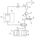
図に示したマイクロ透析装置は主としてつぎのものからなる。すなわち、被検査者の皮下組織に挿入可能な微量透析ゾンデ10、グルコースを含む灌流液を微量透析ゾンデ10にインターバル方式で灌流する灌流装置12、14、通過する透析液のグルコース含有量を測定する通過流測定区画16、灌流液グルコースの初期含有量を組織液のグルコース含有量と等しくする制御装置18、20、そして組織液のグルコース含有量を測定する評価ユニット22である。
【0019】
微量透析ゾンデ10は透析膜24を備え、この透析膜を介して、ゾンデ内に存在する灌流液とゾンデを取り巻くすきまにある液体のあいだでグルコースの拡散交換が行なわれ、その際透析液が得られる。そのため管状かつ二重空洞状のゾンデハウジング25は、透析膜24が少なくともその境界の一部をなす貫流路を備え、この貫流路はゾンデ領域の中心にあって、入口側は灌流液を送り込む灌流液導管26と、出口側は透析プロセスの際に灌流液から生じる透析液を排出する透析液導管28と連結している。透析液は透析液導管28を経由して測定区画16へ、そこから収集容器30へと導かれる。適切なこの種の微量透析ゾンデは、とくにドイツ特許公開第3342170号公報または米国特許第4,694,832号明細書においてよく知られており、スウェーデンのソルナにある、シーエムエー/マイクロディアリシス エービー(CMA/Microdialysis AB)社から、「シーエムエー 60 マイクロディアリシス カテーテル(CMA 60 Microdialysis Catheter)」または「シーエムエー 70 ブレイン マイクロディアリシスカテーテル(CMA 70 Brain Microdialysis Catheter)」の名称で入手することができる。
【0020】
微量透析ゾンデ10にグルコースを含む灌流液をインターバル方式で加えるために、灌流装置は灌流液貯蔵部12と搬送ユニット14を備える。灌流液貯蔵部12は2つの別々なタンク32、34で構成され、これらのタンクの一方はグルコースを含まない灌流液36を、他方は指定された濃度のグルコースを混合された灌流液38を収めている。液38のグルコース濃度は4g/l以上とするのが目的に合っており、そうすれば液36、38を後段で説明する方法で混合することにより、灌流液は組織グルコースの生理的範囲をカバーすることができる。数マイクロリットルという配量の搬送ストロークで、灌流液を微量透析ゾンデ10と後続の測定区画16を通して搬送するため、インターバル方式で動作するチューブ型ポンプ14を搬送ユニットとして備えている。搬送休止のあいだ微量透析ゾンデ10を体外に配置された測定区画16に対して遮断するため、このポンプは透析液導管28の中に配置するのが有利である。
【0021】
灌流液またはその中に含まれている透析液が流れる測定区画16は、連続的信号検知のための電極センサ40を備えるが、このセンサは、電気化学的・酵素的(elektrochemisch-enzymatisch)に作用する。センサ40は、ここには図示しないが電解液の役割をする透析液の作用を受ける測定電極を備え、この測定電極を介して、透析液のグルコース含有量に線形に依存する測定信号を、連続的測定電流として継続して捕らえる。この測定原理のより詳細な細部は、従来の技術ではとくにドイツ特許公開第4401400号公報において知られており、これを本明細書においてとくに参照している。当然のことながら、微量透析ゾンデ中で灌流液と体液とのあいだで濃度勾配の完全な平衡が生じるか、または濃度一様化の程度が知られていれば、測定信号は体液のグルコース含有量をも反映する。
【0022】
センサ40の測定信号は、後続の測定用変換器42で電子的に処理され、クロックパルスをあたえられたアナログ−デジタル変換器を経由し、デジタル値の時間的な列となって、制御装置のデジタル制御器18に供給される。この場合制御器18はマイクロコントローラーを備え、同時にこのマイクロコントローラーは評価ユニット22を形成する。制御器18の出口側は、灌流液グルコースの初期含有量を調整するため、制御装置のアクチュエータである制御弁20と連結している。制御弁20は灌流液導管26を、スプリングによりセンタリングされた第1のスイッチポジションではグルコースを含まないタンク32と連結し、電磁的に作動された第2のスイッチポジションではグルコースを含むタンク34と連結する。そして、切替周波数の適切な選択による同期動作によって、チューブ型ポンプ14に吸引される液36、38の量の比により、そしてまた後続の灌流液導管26で生じる液流混合により灌流液のグルコース濃度を、制御量として制御することができる。
【0023】
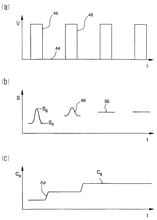
この微量透析装置を動作させるときは、図2(a)のダイアグラムのように、静止インターバルまたは透析インターバル44によってたがいに分離された搬送インターバル46では、ポンプにより灌流液は微量透析ゾンデ10と測定区画16を通過する。この場合透析インターバル44は、微量透析ゾンデ10にとどまる灌流液体積のグルコース含有量が、拡散交換によってほとんど完全に組織グルコースに等しくなるような長さとする。これに対して搬送インターバル46ではゾンデ内通過が早いため、灌流液のグルコース濃度はほとんど変わらない。濃度一様化の程度または「リカバリー」は、とくに微量透析ゾンデ10における灌流液の滞留時間または速度に左右される。図2に示す実施形態では、搬送を中断する場合の透析インターバルの長さは360秒であるが、他方搬送インターバルの長さは搬送流
【0024】
【数3】
が0.08μl/sのとき180秒である。
【0026】
いずれの搬送ストロークでも、先行する透析インターバルで形成された柱状搬送物または液体柱状物の形態の透析液は、微量透析ゾンデ10から少なくとも透析液導管28に、好ましくは測定区画16まで完全に押し出される。これに対応して測定区画では搬送インターバル46のあいだ、信号Sが捕らえられる。この信号は、組織グルコースと灌流液グルコースのあいだに濃度差があるときは、組織グルコースに対応するピーク値または極値Sgと、灌流液グルコースの初期濃度に対応する基準線値S0を示す(図2(b)のダイアグラム参照)。
【0027】
灌流液の初期グルコースを組織グルコースに等しくするため、評価ユニット22を用いて測定信号から組織グルコースに対応する指令量を導き出し、制御量すなわち初期グルコースの瞬間値に対する制御差を求めながら、この指令量を制御器18に供給する。この場合指令量は信号ピークSgと相関するが、制御量は基準線値S0により検知できる。
【0028】
とくに簡単な制御には、指令量または制御差を信号ピークSgの定性的検知によって求め、灌流液グルコースの初期含有量を二位置動作プロセスによって不連続に適合させれば充分である。この場合アクチュエータ20によって、正の信号ピーク(信号ピーク48)が生じたときにはグルコース初期含有量cpをプリセットされた値Δp相当分増加し、負のピーク(信号一時低下。ここには示さない)の場合はそれに応じて減じる。この制御動作には、透析インターバルのあいだのわずかな濃度一様化またはリカバリー(<50%)ですでに充分であり、その結果透析時間をそれに応じて減じることができる。
【0029】
調整信号は、搬送インターバルが等しいままの場合は、透析インターバルが経過してはじめて変換することができる。この不動作時間を避けるため、制御偏差がある場合は各瞬間の搬送インターバルの時間を延長して、グルコース含有量を再調整した灌流液がただちに微量透析ゾンデ10に達するようにすることが考えられる。
【0030】
制御偏差がわずかであるときは最後に一定信号50が観察される。この信号は、グルコース初期含有量cpが組織グルコースのその時点の値cgと一致することを示す(図2(c)参照)。このようにすれば、誤差を生じやすい測定信号直接評価を行なわずにすみ、組織グルコースを一定信号50が生じたときの平衡値cpから間接的に求めることができる。これによりさらに測定の手間を加えなくても、評価ユニット22を用い、場合によっては割り当てられた較正値と比較することによって、その時点の操作量すなわちバルブ20の切替周波数から、灌流液グルコースの初期含有量を決定することができる。
【0031】
測定信号の定量的評価を行なう方法は、パターン認識によって、すなわち記憶媒体にファイルされた較正済み信号パターンと測定信号のその時点の信号推移を比較することによって求めるというものである。これに代わる方法としては、制御差を測定信号の信号推移のピーク値と基準線値の差として求めることができる。したがってこの場合制御量の実際値は、基準線値S0として測定により求められる。前述したように、センサの信号は高い流れの位相のあいだのみ評価される。この信号は、透析段階に属し、組織グルコース濃度に比例する部分Sgと、初期灌流液グルコース濃度をほぼ表わす高流速部分に属する信号とからなる。感度変動の影響を受けないで制御できるようにするために、組織液のグルコース含有量cに応じて、つぎの関係式から指令量を求めることができる。
【0032】
【数4】
ここでc0は操作量から求めることが可能な灌流液グルコースの各瞬間の初期含有量である。
【0034】
さらなる影響パラメータを参酌するために、組織グルコース濃度を以下のように計算してもよい。
【0035】
【数5】
ここで、a、bは、搬送インターバルのあいだの分散を補償し、リカバリーの効果を混合および残留させ、経験的に決定された補正要素である。ピーク値Sgは、搬送インターバルのあいだの所定の時点におけるセンサ値である。この時点は実験により決定され、微小灌流プローブからグルコース感知ユニット、すなわち測定セル16までの灌流液を押すのにかかる時間によって与えられる。S0はSgの時点の前後60秒のセンサ値の平均値として得ることができる。
【0037】
グルコース含有量の自己適応制御の前記原理を、連続的灌流による測定に応用することが考えられる。基本的にこの微量透析技術は、人体の皮下測定のみに限定されない。むしろ血液のようなほかの体液を場合によっては体外で検査することもできる。
【図面の簡単な説明】
【図1】組織液中グルコースの濃度測定のためのマイクロ透析装置の構成図である。
【図2】灌流液の流れ、透析液のグルコース測定信号および適合により再調整された灌流液のグルコース濃度のそれぞれの時系列変化を示すダイヤグラムである。[0001]
BACKGROUND OF THE INVENTION
The invention relates to a method and a device according to the preamble of
[0002]
[Prior art]
A method and apparatus of this kind is known from WO 97/42868. In this case, it has been proposed to perform intermittent transport strokes, one to allow continuous signal calibration and two to speed up the measurement process. In this case, during the resting phase in the middle of each transport stroke, the portion of the perfusate that is then in the microdialysis sonde is equalized to the tissue fluid glucose concentration by the dialysis process. However, the adjacent volume region in the liquid column that is subsequently additionally transported at a high speed remains almost unchanged. Corresponding to the concentration gradient, a signal peak is observed during the transport stroke in the measurement section, and the glucose concentration of not only dialysate but also body fluid can be measured from this signal peak. Calibration uses a perfusate containing glucose, and the specified glucose concentration of the perfusate defines the baseline value of the signal peak. In this case, the precondition is that the sensor behaves linearly as well as the concentration is completely balanced during the dialysis phase. And it is assumed that the density image in the volume carried away from the sonde does not collapse to the measurement section. However, this latter assumption is often not true, especially in the case of laminar flow, since mixing occurs. In addition, diffusion exchange prevents glucose balance in the tissue surrounding the sonde.
[0003]
[Problems to be solved by the invention]
With this as a starting point, the object of the present invention is to prevent the above-mentioned drawbacks, particularly troubles in concentration in body fluids, and to enable accurate glucose measurement while shortening the dialysis time.
[0004]
[Means for Solving the Problems]
In order to solve this problem, a combination of features described in
[0005]
The idea underlying the present invention is to adapt the glucose content of the perfusate to the glucose concentration of the body fluid by self-regulation or adaptation. In response to this problem, the following is proposed. That is, it is proposed that the initial glucose content of the perfusate is made equal to the glucose content of the body fluid according to the command amount derived from the measurement signal of the measurement section using the control device. This equilibrates the glucose gradient and correspondingly reduces the time required for complete dialysis equilibration. Furthermore, troubles caused by the glucose gradient can be prevented even when the flow rate of the microdialysis sonde or the glucose fluctuation of the body fluid is large.
[0006]
A particularly preferred embodiment of the present invention intends to define the initial content of glucose in the perfusate at each instant as a measure of the glucose content of the body fluid when the control deviation is small. As a result, quantitative concentration measurement can be performed indirectly via the actual value of the control amount at each moment. On the other hand, the measurement signal that is continuously captured in the measurement section serves only as an input quantity for the control device. As an alternative or complementary method, it is basically possible to indirectly derive the glucose content of the body fluid from the measurement signal.
[0007]
As an advantageous method, the initial glucose content in the perfusate is determined from the manipulated variable of the actuator of the controller. By this measurement, the initial content can be accurately determined, for example, from the values standardized in the table, and in this case no further glucose sensors need be added. In principle, however, the glucose content of the perfusate can also be measured before introducing it into the microdialysis sonde.
[0008]
For a variable setting, it is advantageous to control the initial glucose content of the perfusate by preparing perfusates with different glucose concentrations in two separate tanks and mixing the flows from them. .
[0009]
According to a particularly preferred embodiment of the present invention, the perfusate is directed and passed through the microdialysis sonde in the conveying and dialysis intervals, which continue in succession and at different flow rates. In this case, the flow rate is higher in the transport interval than in the dialysis interval. This shortens the measurement time and makes the evaluation even easier. This is because the existing concentration gradient can be detected qualitatively via the measurement signal even in the case of only partial dialysis equilibrium. In this case, the flow rate of the transport interval should be fast enough that the initial glucose content of the perfusate is maintained as it passes through the microdialysis sonde. In contrast, during the dialysis interval, transport is interrupted, or at least the flow rate is reduced to such an extent that the glucose concentration of the dialysate approximates the glucose concentration of the body fluid.
[0010]
In particular, in the case of a simple control method, the command amount for determining the set value is obtained by integration or differentiation of the time transition of the measurement signal or by qualitative detection of the signal peak in the time transition of the measurement signal. As an alternative method, the command amount can be obtained by comparing the current signal transition of the measurement signal with the calibrated signal pattern filed in the storage medium. Another method is to obtain the command amount from the peak value of the signal transition of the measurement signal at each conveyance interval. In order to quantitatively define the control device input signal, the command amount can be obtained from the following relational expression corresponding to the glucose content c of the body fluid.
[0011]
[Expression 2]
Where S g is the peak value of the measurement signal at the transport interval, S 0 is also its baseline value, c 0 is the initial initial content of glucose in the perfusate, and a and b are the variances during the transport interval. This is an empirically determined correction factor that compensates for, and mixes and retains the recovery effect.
[0013]
Particularly in the case of simple controller functions, the initial glucose content of the perfusate is controlled discontinuously by a two-position operating process. In this case, when there is a control deviation, the initial glucose content of the perfusate is changed by a predetermined adjustment value.
[0014]
Regarding the measurement arrangement, in order to solve the above-described problems, a control device is proposed that makes the initial glucose concentration of the perfusate equal to the bodily glucose concentration according to the command amount derived from the measurement signal of the measurement section. A preferred embodiment comprises one evaluation unit, which is used when the control deviation is small, to determine the glucose content of the body fluid according to the initial initial content of glucose in the perfusate.
[0015]
The perfusion apparatus includes a perfusate storage unit and a transport unit that transports the perfusate. The transport unit preferably operates in an interval manner, i.e. it produces a different transport flow for each successive time interval. In order to be able to change the initial glucose content, it is advantageous if the perfusate reservoir is provided with at least two separate tanks for containing perfusates with different glucose concentrations. Advantageously, the perfusate reservoir comprises a first tank that contains a perfusate that does not contain glucose and a second tank that contains a perfusate that contains glucose. In the latter tank, the glucose content should then be higher than the physiological boundary value. An adjusting device for adjusting the initial content of perfusate glucose and having a simple structure includes a liquid mixing device including a mixing valve or an adjusting valve that can be switched by a clock pulse as an actuator. In this case, it is convenient if this liquid mixing device is connected to at least two tanks for supplying perfusate having different glucose concentrations on the inflow side, and connected to a perfusion liquid conduit connected to the microdialysis sonde on the outflow side. is there.
[0016]
In order to be able to change the processing of the signal flow, the control device comprises a digitally operated controller, preferably this controller comprises a microcontroller.
[0017]
DETAILED DESCRIPTION OF THE INVENTION
Hereinafter, the present invention will be described in detail by way of embodiments shown in schematic diagrams.
[0018]
The microdialyzer shown in the figure mainly comprises the following. That is, the
[0019]
The
[0020]
In order to add the perfusate containing glucose to the
[0021]
The
[0022]
The measurement signal of the
[0023]
When the microdialyzer is operated, as shown in the diagram of FIG. 2 (a), the perfusate is separated from the
[Equation 3]
Is 180 seconds when is 0.08 μl / s.
[0026]
In any transport stroke, the dialysate in the form of a column or liquid column formed in the preceding dialysis interval is pushed completely out of the
[0027]
In order to make the initial glucose of the perfusate equal to the tissue glucose, a command amount corresponding to the tissue glucose is derived from the measurement signal using the
[0028]
The particularly simple control, obtains the command amount or the control difference by qualitative detection of signal peaks S g, it is sufficient to ask the initial content of the perfusate glucose adapted discontinuously by two-position operation process. In this case, when a positive signal peak (signal peak 48) is generated by the
[0029]
The adjustment signal can be converted only after the dialysis interval has passed if the transport interval remains equal. In order to avoid this non-operation time, if there is a control deviation, it is possible to extend the time of the transport interval at each moment so that the perfusate whose glucose content is readjusted reaches the
[0030]
Finally, a
[0031]
A method for quantitative evaluation of the measurement signal is to obtain it by pattern recognition, i.e. by comparing the current signal transition of the measurement signal with a calibrated signal pattern filed in a storage medium. As an alternative method, the control difference can be obtained as the difference between the peak value of the signal transition of the measurement signal and the reference line value. Therefore, in this case, the actual value of the control amount is obtained by measurement as the reference line value S 0 . As previously mentioned, the sensor signal is evaluated only during high flow phases. This signal belongs to dialysis stage, consisting of a portion S g which is proportional to the tissue glucose concentration signal and belonging initial perfusate glucose concentration in the high flow rate portion substantially represented. In order to be able to control without being affected by the sensitivity fluctuation, the command amount can be obtained from the following relational expression according to the glucose content c of the tissue fluid.
[0032]
[Expression 4]
Here, c 0 is the initial initial content of perfusate glucose that can be determined from the manipulated value.
[0034]
To take into account further influence parameters, the tissue glucose concentration may be calculated as follows.
[0035]
[Equation 5]
Here, a and b are correction factors determined empirically by compensating for dispersion during the conveyance interval, mixing and remaining the recovery effect. The peak value Sg is a sensor value at a predetermined time point during the conveyance interval. This point in time is determined experimentally and given by the time it takes to push the perfusate from the microperfusion probe to the glucose sensing unit, ie the
[0037]
It is conceivable to apply the principle of self-adaptive control of glucose content to measurement by continuous perfusion. Basically, this microdialysis technique is not limited only to subcutaneous measurement of the human body. Rather, other body fluids such as blood can be examined outside the body in some cases.
[Brief description of the drawings]
FIG. 1 is a configuration diagram of a microdialysis apparatus for measuring the concentration of glucose in tissue fluid.
FIG. 2 is a diagram showing the respective time-series changes in perfusate flow, dialysate glucose measurement signal and glucose concentration in the perfusate readjusted by adaptation.
Claims (9)
Applications Claiming Priority (2)
| Application Number | Priority Date | Filing Date | Title |
|---|---|---|---|
| DE19935165:1 | 1999-07-28 | ||
| DE19935165A DE19935165A1 (en) | 1999-07-28 | 1999-07-28 | Method and arrangement for determining the concentration of glucose in a body fluid |
Publications (2)
| Publication Number | Publication Date |
|---|---|
| JP2001066313A JP2001066313A (en) | 2001-03-16 |
| JP4159727B2 true JP4159727B2 (en) | 2008-10-01 |
Family
ID=7916162
Family Applications (1)
| Application Number | Title | Priority Date | Filing Date |
|---|---|---|---|
| JP2000217432A Expired - Fee Related JP4159727B2 (en) | 1999-07-28 | 2000-07-18 | Method and apparatus for measuring glucose concentration in body fluid |
Country Status (5)
| Country | Link |
|---|---|
| US (2) | US6852500B1 (en) |
| EP (1) | EP1072222B1 (en) |
| JP (1) | JP4159727B2 (en) |
| AT (1) | ATE268141T1 (en) |
| DE (2) | DE19935165A1 (en) |
Families Citing this family (135)
| Publication number | Priority date | Publication date | Assignee | Title |
|---|---|---|---|---|
| US6391005B1 (en) | 1998-03-30 | 2002-05-21 | Agilent Technologies, Inc. | Apparatus and method for penetration with shaft having a sensor for sensing penetration depth |
| US6949816B2 (en) | 2003-04-21 | 2005-09-27 | Motorola, Inc. | Semiconductor component having first surface area for electrically coupling to a semiconductor chip and second surface area for electrically coupling to a substrate, and method of manufacturing same |
| US8465425B2 (en) | 1998-04-30 | 2013-06-18 | Abbott Diabetes Care Inc. | Analyte monitoring device and methods of use |
| US6175752B1 (en) | 1998-04-30 | 2001-01-16 | Therasense, Inc. | Analyte monitoring device and methods of use |
| US8688188B2 (en) | 1998-04-30 | 2014-04-01 | Abbott Diabetes Care Inc. | Analyte monitoring device and methods of use |
| US8974386B2 (en) | 1998-04-30 | 2015-03-10 | Abbott Diabetes Care Inc. | Analyte monitoring device and methods of use |
| US8480580B2 (en) | 1998-04-30 | 2013-07-09 | Abbott Diabetes Care Inc. | Analyte monitoring device and methods of use |
| US8346337B2 (en) | 1998-04-30 | 2013-01-01 | Abbott Diabetes Care Inc. | Analyte monitoring device and methods of use |
| US9066695B2 (en) | 1998-04-30 | 2015-06-30 | Abbott Diabetes Care Inc. | Analyte monitoring device and methods of use |
| DE19935165A1 (en) * | 1999-07-28 | 2001-02-01 | Roche Diagnostics Gmbh | Method and arrangement for determining the concentration of glucose in a body fluid |
| US8641644B2 (en) | 2000-11-21 | 2014-02-04 | Sanofi-Aventis Deutschland Gmbh | Blood testing apparatus having a rotatable cartridge with multiple lancing elements and testing means |
| US6560471B1 (en) | 2001-01-02 | 2003-05-06 | Therasense, Inc. | Analyte monitoring device and methods of use |
| EP1397068A2 (en) | 2001-04-02 | 2004-03-17 | Therasense, Inc. | Blood glucose tracking apparatus and methods |
| US9427532B2 (en) | 2001-06-12 | 2016-08-30 | Sanofi-Aventis Deutschland Gmbh | Tissue penetration device |
| US9795747B2 (en) | 2010-06-02 | 2017-10-24 | Sanofi-Aventis Deutschland Gmbh | Methods and apparatus for lancet actuation |
| US9226699B2 (en) | 2002-04-19 | 2016-01-05 | Sanofi-Aventis Deutschland Gmbh | Body fluid sampling module with a continuous compression tissue interface surface |
| US7025774B2 (en) | 2001-06-12 | 2006-04-11 | Pelikan Technologies, Inc. | Tissue penetration device |
| EP1404235A4 (en) | 2001-06-12 | 2008-08-20 | Pelikan Technologies Inc | METHOD AND APPARATUS FOR INTEGRATED LANCET LAUNCH DEVICE ON BLOOD SAMPLING CARTRIDGE |
| US7981056B2 (en) | 2002-04-19 | 2011-07-19 | Pelikan Technologies, Inc. | Methods and apparatus for lancet actuation |
| AU2002315180A1 (en) | 2001-06-12 | 2002-12-23 | Pelikan Technologies, Inc. | Electric lancet actuator |
| DE60234598D1 (en) | 2001-06-12 | 2010-01-14 | Pelikan Technologies Inc | SELF-OPTIMIZING LANZET DEVICE WITH ADAPTANT FOR TEMPORAL FLUCTUATIONS OF SKIN PROPERTIES |
| US8337419B2 (en) | 2002-04-19 | 2012-12-25 | Sanofi-Aventis Deutschland Gmbh | Tissue penetration device |
| AT412060B (en) * | 2001-07-06 | 2004-09-27 | Schaupp Lukas Dipl Ing Dr Tech | METHOD FOR MEASURING CONCENTRATIONS IN LIVING ORGANISMS BY MEANS OF MICRODIALYSIS AND AND DEVICE FOR IMPLEMENTING THIS METHOD |
| US10173008B2 (en) * | 2002-01-29 | 2019-01-08 | Baxter International Inc. | System and method for communicating with a dialysis machine through a network |
| US7674232B2 (en) | 2002-04-19 | 2010-03-09 | Pelikan Technologies, Inc. | Method and apparatus for penetrating tissue |
| US7331931B2 (en) | 2002-04-19 | 2008-02-19 | Pelikan Technologies, Inc. | Method and apparatus for penetrating tissue |
| US9795334B2 (en) | 2002-04-19 | 2017-10-24 | Sanofi-Aventis Deutschland Gmbh | Method and apparatus for penetrating tissue |
| US8579831B2 (en) | 2002-04-19 | 2013-11-12 | Sanofi-Aventis Deutschland Gmbh | Method and apparatus for penetrating tissue |
| US7229458B2 (en) | 2002-04-19 | 2007-06-12 | Pelikan Technologies, Inc. | Method and apparatus for penetrating tissue |
| US8360992B2 (en) | 2002-04-19 | 2013-01-29 | Sanofi-Aventis Deutschland Gmbh | Method and apparatus for penetrating tissue |
| US8702624B2 (en) | 2006-09-29 | 2014-04-22 | Sanofi-Aventis Deutschland Gmbh | Analyte measurement device with a single shot actuator |
| US7175642B2 (en) | 2002-04-19 | 2007-02-13 | Pelikan Technologies, Inc. | Methods and apparatus for lancet actuation |
| US7297122B2 (en) | 2002-04-19 | 2007-11-20 | Pelikan Technologies, Inc. | Method and apparatus for penetrating tissue |
| US8267870B2 (en) | 2002-04-19 | 2012-09-18 | Sanofi-Aventis Deutschland Gmbh | Method and apparatus for body fluid sampling with hybrid actuation |
| US7198606B2 (en) | 2002-04-19 | 2007-04-03 | Pelikan Technologies, Inc. | Method and apparatus for a multi-use body fluid sampling device with analyte sensing |
| US7909778B2 (en) | 2002-04-19 | 2011-03-22 | Pelikan Technologies, Inc. | Method and apparatus for penetrating tissue |
| US7892185B2 (en) | 2002-04-19 | 2011-02-22 | Pelikan Technologies, Inc. | Method and apparatus for body fluid sampling and analyte sensing |
| US7892183B2 (en) | 2002-04-19 | 2011-02-22 | Pelikan Technologies, Inc. | Method and apparatus for body fluid sampling and analyte sensing |
| US9248267B2 (en) | 2002-04-19 | 2016-02-02 | Sanofi-Aventis Deustchland Gmbh | Tissue penetration device |
| US7976476B2 (en) | 2002-04-19 | 2011-07-12 | Pelikan Technologies, Inc. | Device and method for variable speed lancet |
| US9314194B2 (en) | 2002-04-19 | 2016-04-19 | Sanofi-Aventis Deutschland Gmbh | Tissue penetration device |
| US7648468B2 (en) * | 2002-04-19 | 2010-01-19 | Pelikon Technologies, Inc. | Method and apparatus for penetrating tissue |
| US7901362B2 (en) | 2002-04-19 | 2011-03-08 | Pelikan Technologies, Inc. | Method and apparatus for penetrating tissue |
| US7491178B2 (en) | 2002-04-19 | 2009-02-17 | Pelikan Technologies, Inc. | Method and apparatus for penetrating tissue |
| US8221334B2 (en) | 2002-04-19 | 2012-07-17 | Sanofi-Aventis Deutschland Gmbh | Method and apparatus for penetrating tissue |
| US7232451B2 (en) | 2002-04-19 | 2007-06-19 | Pelikan Technologies, Inc. | Method and apparatus for penetrating tissue |
| US7547287B2 (en) | 2002-04-19 | 2009-06-16 | Pelikan Technologies, Inc. | Method and apparatus for penetrating tissue |
| US8784335B2 (en) | 2002-04-19 | 2014-07-22 | Sanofi-Aventis Deutschland Gmbh | Body fluid sampling device with a capacitive sensor |
| US8574895B2 (en) | 2002-12-30 | 2013-11-05 | Sanofi-Aventis Deutschland Gmbh | Method and apparatus using optical techniques to measure analyte levels |
| US7811231B2 (en) | 2002-12-31 | 2010-10-12 | Abbott Diabetes Care Inc. | Continuous glucose monitoring system and methods of use |
| US20070032812A1 (en) * | 2003-05-02 | 2007-02-08 | Pelikan Technologies, Inc. | Method and apparatus for a tissue penetrating device user interface |
| DE602004028463D1 (en) | 2003-05-30 | 2010-09-16 | Pelikan Technologies Inc | METHOD AND DEVICE FOR INJECTING LIQUID |
| US20040253736A1 (en) * | 2003-06-06 | 2004-12-16 | Phil Stout | Analytical device with prediction module and related methods |
| WO2004107964A2 (en) | 2003-06-06 | 2004-12-16 | Pelikan Technologies, Inc. | Blood harvesting device with electronic control |
| US8066639B2 (en) | 2003-06-10 | 2011-11-29 | Abbott Diabetes Care Inc. | Glucose measuring device for use in personal area network |
| WO2006001797A1 (en) | 2004-06-14 | 2006-01-05 | Pelikan Technologies, Inc. | Low pain penetrating |
| US8282576B2 (en) | 2003-09-29 | 2012-10-09 | Sanofi-Aventis Deutschland Gmbh | Method and apparatus for an improved sample capture device |
| EP1680014A4 (en) | 2003-10-14 | 2009-01-21 | Pelikan Technologies Inc | METHOD AND APPARATUS PROVIDING A VARIABLE USER INTERFACE |
| EP1706026B1 (en) | 2003-12-31 | 2017-03-01 | Sanofi-Aventis Deutschland GmbH | Method and apparatus for improving fluidic flow and sample capture |
| US7822454B1 (en) | 2005-01-03 | 2010-10-26 | Pelikan Technologies, Inc. | Fluid sampling device with improved analyte detecting member configuration |
| GB0402131D0 (en) | 2004-01-30 | 2004-03-03 | Isis Innovation | Delivery method |
| WO2005089103A2 (en) | 2004-02-17 | 2005-09-29 | Therasense, Inc. | Method and system for providing data communication in continuous glucose monitoring and management system |
| US20050209518A1 (en) * | 2004-03-17 | 2005-09-22 | Therafuse, Inc. | Self-calibrating body analyte monitoring system |
| WO2006011062A2 (en) | 2004-05-20 | 2006-02-02 | Albatros Technologies Gmbh & Co. Kg | Printable hydrogel for biosensors |
| WO2005120365A1 (en) | 2004-06-03 | 2005-12-22 | Pelikan Technologies, Inc. | Method and apparatus for a fluid sampling device |
| US9775553B2 (en) | 2004-06-03 | 2017-10-03 | Sanofi-Aventis Deutschland Gmbh | Method and apparatus for a fluid sampling device |
| US9788771B2 (en) | 2006-10-23 | 2017-10-17 | Abbott Diabetes Care Inc. | Variable speed sensor insertion devices and methods of use |
| US20060167382A1 (en) * | 2004-12-30 | 2006-07-27 | Ajay Deshmukh | Method and apparatus for storing an analyte sampling and measurement device |
| WO2006072004A2 (en) * | 2004-12-30 | 2006-07-06 | Pelikan Technologies, Inc. | Method and apparatus for analyte measurement test time |
| US8652831B2 (en) | 2004-12-30 | 2014-02-18 | Sanofi-Aventis Deutschland Gmbh | Method and apparatus for analyte measurement test time |
| US8112240B2 (en) | 2005-04-29 | 2012-02-07 | Abbott Diabetes Care Inc. | Method and apparatus for providing leak detection in data monitoring and management systems |
| EP1719447A1 (en) * | 2005-05-07 | 2006-11-08 | F. Hoffmann-La Roche AG | Method and device for determining glucose concentration in lymph |
| EP1783484A1 (en) * | 2005-11-04 | 2007-05-09 | F.Hoffmann-La Roche Ag | Device and method for measuring the concentration of a substance in a fluid |
| US7766829B2 (en) | 2005-11-04 | 2010-08-03 | Abbott Diabetes Care Inc. | Method and system for providing basal profile modification in analyte monitoring and management systems |
| US20070106200A1 (en) * | 2005-11-08 | 2007-05-10 | Brian Levy | Intraocular shunt device and method |
| US8226891B2 (en) | 2006-03-31 | 2012-07-24 | Abbott Diabetes Care Inc. | Analyte monitoring devices and methods therefor |
| US7620438B2 (en) | 2006-03-31 | 2009-11-17 | Abbott Diabetes Care Inc. | Method and system for powering an electronic device |
| US7920907B2 (en) | 2006-06-07 | 2011-04-05 | Abbott Diabetes Care Inc. | Analyte monitoring system and method |
| EP1870027A1 (en) | 2006-06-21 | 2007-12-26 | Trace Analytics GmbH | Devices and method for detecting an analyte |
| DE102006041762A1 (en) * | 2006-09-04 | 2008-03-06 | Daimler Ag | Apparatus and method for moistening a gas stream flowing to a fuel cell |
| EP2079828A4 (en) * | 2006-11-09 | 2010-03-10 | Sense Ltd G | System and method for pseudo-continuous measurement of metabolite concentrations in a mammalian body |
| EP1922987A1 (en) | 2006-11-17 | 2008-05-21 | Trace Analytics GmbH | Sampling device and sampling method |
| US8732188B2 (en) | 2007-02-18 | 2014-05-20 | Abbott Diabetes Care Inc. | Method and system for providing contextual based medication dosage determination |
| US8930203B2 (en) | 2007-02-18 | 2015-01-06 | Abbott Diabetes Care Inc. | Multi-function analyte test device and methods therefor |
| US8123686B2 (en) | 2007-03-01 | 2012-02-28 | Abbott Diabetes Care Inc. | Method and apparatus for providing rolling data in communication systems |
| US8456301B2 (en) | 2007-05-08 | 2013-06-04 | Abbott Diabetes Care Inc. | Analyte monitoring system and methods |
| US7928850B2 (en) | 2007-05-08 | 2011-04-19 | Abbott Diabetes Care Inc. | Analyte monitoring system and methods |
| US8665091B2 (en) | 2007-05-08 | 2014-03-04 | Abbott Diabetes Care Inc. | Method and device for determining elapsed sensor life |
| US8461985B2 (en) | 2007-05-08 | 2013-06-11 | Abbott Diabetes Care Inc. | Analyte monitoring system and methods |
| WO2009021052A1 (en) * | 2007-08-06 | 2009-02-12 | University Of Kentucky Research Foundation | Polypeptides, systems, and methods useful for detecting glucose |
| US9220678B2 (en) | 2007-12-24 | 2015-12-29 | The University Of Queensland | Coating method |
| US20090209883A1 (en) * | 2008-01-17 | 2009-08-20 | Michael Higgins | Tissue penetrating apparatus |
| EP2247527A4 (en) | 2008-02-07 | 2014-10-29 | Univ Queensland | Patch production |
| WO2009126900A1 (en) | 2008-04-11 | 2009-10-15 | Pelikan Technologies, Inc. | Method and apparatus for analyte detecting device |
| AU2009250341A1 (en) * | 2008-05-23 | 2009-11-26 | The University Of Queensland | Analyte detection using a needle projection patch |
| US8103456B2 (en) | 2009-01-29 | 2012-01-24 | Abbott Diabetes Care Inc. | Method and device for early signal attenuation detection using blood glucose measurements |
| US9375169B2 (en) | 2009-01-30 | 2016-06-28 | Sanofi-Aventis Deutschland Gmbh | Cam drive for managing disposable penetrating member actions with a single motor and motor and control system |
| US20100198034A1 (en) | 2009-02-03 | 2010-08-05 | Abbott Diabetes Care Inc. | Compact On-Body Physiological Monitoring Devices and Methods Thereof |
| US10022081B2 (en) | 2009-03-10 | 2018-07-17 | Trace Analytics, Gmbh | Sampling device and sampling method |
| EP2236077A1 (en) * | 2009-03-31 | 2010-10-06 | Sensile Pat AG | Medical device for measuring an analyte concentration |
| US9226701B2 (en) | 2009-04-28 | 2016-01-05 | Abbott Diabetes Care Inc. | Error detection in critical repeating data in a wireless sensor system |
| WO2010138856A1 (en) | 2009-05-29 | 2010-12-02 | Abbott Diabetes Care Inc. | Medical device antenna systems having external antenna configurations |
| US8993331B2 (en) | 2009-08-31 | 2015-03-31 | Abbott Diabetes Care Inc. | Analyte monitoring system and methods for managing power and noise |
| EP2473098A4 (en) | 2009-08-31 | 2014-04-09 | Abbott Diabetes Care Inc | Analyte signal processing device and methods |
| US9320461B2 (en) | 2009-09-29 | 2016-04-26 | Abbott Diabetes Care Inc. | Method and apparatus for providing notification function in analyte monitoring systems |
| CA2780871C (en) | 2009-11-16 | 2018-12-11 | Maquet Critical Care Ab | Self-flowing measuring system |
| DK3622883T3 (en) | 2010-03-24 | 2021-07-19 | Abbott Diabetes Care Inc | Introduces medical devices and methods for introducing and using medical devices |
| US8965476B2 (en) | 2010-04-16 | 2015-02-24 | Sanofi-Aventis Deutschland Gmbh | Tissue penetration device |
| WO2012006677A1 (en) | 2010-07-14 | 2012-01-19 | The University Of Queensland | Patch applying apparatus |
| JP5762833B2 (en) * | 2011-06-09 | 2015-08-12 | 日機装株式会社 | Biological component measuring device |
| WO2013053022A1 (en) | 2011-10-12 | 2013-04-18 | The University Of Queensland | Delivery device |
| EP3677182B1 (en) | 2011-11-07 | 2022-05-04 | Abbott Diabetes Care Inc. | Analyte monitoring device and methods |
| FI3300658T3 (en) | 2011-12-11 | 2024-03-01 | Abbott Diabetes Care Inc | ANALYTE SENSOR METHODS |
| US9968306B2 (en) | 2012-09-17 | 2018-05-15 | Abbott Diabetes Care Inc. | Methods and apparatuses for providing adverse condition notification with enhanced wireless communication range in analyte monitoring systems |
| CN104634906B (en) * | 2013-11-07 | 2018-07-13 | 苏州普源精电科技有限公司 | The baseline adjusting method of detached peaks and the chromatographic work station that function is adjusted with baseline |
| CN104634883B (en) * | 2013-11-07 | 2018-04-27 | 苏州普源精电科技有限公司 | A kind of chromatographic work station for having the function of to merge peak base adjustment |
| US9949673B2 (en) * | 2014-08-26 | 2018-04-24 | MAXIM lNTEGRATED PRODUCTS, INC. | System, method and apparatus with multiple reservoirs for in situ calibration of implantable sensors |
| AU2016214968B2 (en) | 2015-02-02 | 2021-02-25 | Vaxxas Pty Limited | Microprojection array applicator and method |
| AU2016260547B2 (en) | 2015-05-14 | 2020-09-03 | Abbott Diabetes Care Inc. | Compact medical device inserters and related systems and methods |
| WO2017045031A1 (en) | 2015-09-18 | 2017-03-23 | Vaxxas Pty Limited | Microprojection arrays with microprojections having large surface area profiles |
| EP3355981B1 (en) | 2015-09-28 | 2025-11-19 | Vaxxas Pty Limited | Microprojection arrays with enhanced skin penetrating properties and methods thereof |
| CN107616799A (en) * | 2016-07-14 | 2018-01-23 | 陈治宇 | A kind of blood glucose on-line real time monitoring system |
| CN107788993A (en) * | 2016-09-06 | 2018-03-13 | 陈治宇 | Anaesthetic concentration on-line real time monitoring system in a kind of blood |
| CN107811642A (en) * | 2016-09-13 | 2018-03-20 | 陈治宇 | Antibiotic drug concentration on-line real time monitoring system in a kind of blood |
| CA3050721A1 (en) | 2017-01-23 | 2018-07-26 | Abbott Diabetes Care Inc. | Systems, devices and methods for analyte sensor insertion |
| EP3606760B1 (en) | 2017-03-31 | 2023-09-27 | Vaxxas Pty Limited | Device and method for coating surfaces |
| US11175128B2 (en) | 2017-06-13 | 2021-11-16 | Vaxxas Pty Limited | Quality control of substrate coatings |
| US11464957B2 (en) | 2017-08-04 | 2022-10-11 | Vaxxas Pty Limited | Compact high mechanical energy storage and low trigger force actuator for the delivery of microprojection array patches (MAP) |
| US10932699B2 (en) | 2017-09-13 | 2021-03-02 | Dexcom, Inc. | Invasive biosensor alignment and retention |
| CN119924827A (en) | 2018-06-07 | 2025-05-06 | 雅培糖尿病护理公司 | Focused sterilization and sterilized sub-assemblies for analyte monitoring systems |
| CN113195022A (en) | 2018-12-21 | 2021-07-30 | 雅培糖尿病护理公司 | Systems, devices, and methods for analyte sensor insertion |
| WO2020148577A1 (en) * | 2019-01-18 | 2020-07-23 | Insense Medical Ltd. | Continuous equilibrium-based diagnostic and therapeutic system |
| CA3188510A1 (en) | 2020-08-31 | 2022-03-03 | Vivek S. RAO | Systems, devices, and methods for analyte sensor insertion |
| US12569168B2 (en) | 2020-09-15 | 2026-03-10 | Abbott Diabetes Care Inc. | Systems, devices, and methods for analyte monitoring |
| CA3186905A1 (en) | 2020-09-15 | 2022-03-24 | Abbott Diabetes Care Inc. | Systems, devices, and methods for an analyte sensor |
Family Cites Families (9)
| Publication number | Priority date | Publication date | Assignee | Title |
|---|---|---|---|---|
| DE4130742A1 (en) * | 1991-09-16 | 1993-03-18 | Inst Diabetestechnologie Gemei | METHOD AND ARRANGEMENT FOR DETERMINING THE CONCENTRATION OF INGREDIENTS IN BODY LIQUIDS |
| GB9320850D0 (en) * | 1993-10-09 | 1993-12-01 | Terwee Thomas H M | Monitoring the concentration of a substance or a group of substances in a body fluid of a human or an animal |
| DE69322968T2 (en) * | 1993-10-22 | 1999-07-08 | Rijksuniversiteit Te Groningen, Groningen | Method and device for continuously monitoring an anolyte level |
| DE4401400A1 (en) | 1994-01-19 | 1995-07-20 | Ernst Prof Dr Pfeiffer | Method and arrangement for continuously monitoring the concentration of a metabolite |
| DE4426694C2 (en) * | 1994-07-28 | 1998-07-23 | Boehringer Mannheim Gmbh | Device for long-term determination of the content of at least one substance in body fluids |
| DE19618597B4 (en) * | 1996-05-09 | 2005-07-21 | Institut für Diabetestechnologie Gemeinnützige Forschungs- und Entwicklungsgesellschaft mbH an der Universität Ulm | Method for determining the concentration of tissue glucose |
| DE19935165A1 (en) * | 1999-07-28 | 2001-02-01 | Roche Diagnostics Gmbh | Method and arrangement for determining the concentration of glucose in a body fluid |
| US6925393B1 (en) * | 1999-11-18 | 2005-08-02 | Roche Diagnostics Gmbh | System for the extrapolation of glucose concentration |
| DE10038835B4 (en) * | 2000-08-04 | 2005-07-07 | Roche Diagnostics Gmbh | Microdialysis system |
-
1999
- 1999-07-28 DE DE19935165A patent/DE19935165A1/en not_active Withdrawn
-
2000
- 2000-07-13 AT AT00115207T patent/ATE268141T1/en not_active IP Right Cessation
- 2000-07-13 DE DE50006664T patent/DE50006664D1/en not_active Expired - Fee Related
- 2000-07-13 EP EP00115207A patent/EP1072222B1/en not_active Expired - Lifetime
- 2000-07-18 JP JP2000217432A patent/JP4159727B2/en not_active Expired - Fee Related
- 2000-07-20 US US09/620,038 patent/US6852500B1/en not_active Expired - Fee Related
-
2004
- 2004-02-19 US US10/782,290 patent/US7169600B2/en not_active Expired - Fee Related
Also Published As
| Publication number | Publication date |
|---|---|
| EP1072222A3 (en) | 2002-01-09 |
| JP2001066313A (en) | 2001-03-16 |
| US20040191848A1 (en) | 2004-09-30 |
| DE50006664D1 (en) | 2004-07-08 |
| EP1072222B1 (en) | 2004-06-02 |
| ATE268141T1 (en) | 2004-06-15 |
| US6852500B1 (en) | 2005-02-08 |
| EP1072222A2 (en) | 2001-01-31 |
| DE19935165A1 (en) | 2001-02-01 |
| US7169600B2 (en) | 2007-01-30 |
Similar Documents
| Publication | Publication Date | Title |
|---|---|---|
| JP4159727B2 (en) | Method and apparatus for measuring glucose concentration in body fluid | |
| JP4057043B2 (en) | Determination of glucose concentration in tissue | |
| US6080583A (en) | Blood analysis system and method for regulating same | |
| ATE191367T1 (en) | DEVICE FOR KIDNEY DIALYSIS | |
| EP1083427A2 (en) | Method and apparatus for determining gas content | |
| JPH01503198A (en) | Calibration method and apparatus for multiple pump fluid flow systems | |
| US20250082833A1 (en) | Measurement of recirculation by means of two interim switches having kinetically different diffusion states | |
| CN113631205A (en) | Measurement of recirculation by means of diffusion equilibrium | |
| EP1232382B1 (en) | Method and apparatus for detection of a bubble in a liquid | |
| CA1103589A (en) | Hemodialysis ultrafiltration system with controlled liquid extraction from blood | |
| US12508351B2 (en) | Extracorporeal blood filtering machine and methods | |
| EP4147640A1 (en) | Urine analysis device | |
| CN101170942A (en) | Apparatus and method for determining glucose content in interstitial fluid | |
| EP4147639A1 (en) | Urine analysis device | |
| JP3183663B2 (en) | Automatic yeast addition device | |
| JPH0363065A (en) | Artificial dialyser | |
| JP2726373B2 (en) | Yeast automatic addition device | |
| WO2024189405A1 (en) | Urine analysis device | |
| WO2024189403A1 (en) | Urine analysis device | |
| WO2024189404A1 (en) | Urine analysis device | |
| JPS5921498B2 (en) | concentration measuring device | |
| JPH05154194A (en) | Continuous measuring instrument for biochemical material | |
| HK1119040A (en) | Method and device for determining the glucose concentration in tissue liquid | |
| JPS649866B2 (en) | ||
| SE512183C2 (en) | Measuring concn. of urea etc. in composite fluid e.g. dialysis fluid |
Legal Events
| Date | Code | Title | Description |
|---|---|---|---|
| A621 | Written request for application examination |
Free format text: JAPANESE INTERMEDIATE CODE: A621 Effective date: 20041208 |
|
| A131 | Notification of reasons for refusal |
Free format text: JAPANESE INTERMEDIATE CODE: A131 Effective date: 20080304 |
|
| A521 | Request for written amendment filed |
Free format text: JAPANESE INTERMEDIATE CODE: A523 Effective date: 20080529 |
|
| TRDD | Decision of grant or rejection written | ||
| A01 | Written decision to grant a patent or to grant a registration (utility model) |
Free format text: JAPANESE INTERMEDIATE CODE: A01 Effective date: 20080624 |
|
| A01 | Written decision to grant a patent or to grant a registration (utility model) |
Free format text: JAPANESE INTERMEDIATE CODE: A01 |
|
| A61 | First payment of annual fees (during grant procedure) |
Free format text: JAPANESE INTERMEDIATE CODE: A61 Effective date: 20080716 |
|
| R150 | Certificate of patent or registration of utility model |
Free format text: JAPANESE INTERMEDIATE CODE: R150 |
|
| FPAY | Renewal fee payment (event date is renewal date of database) |
Free format text: PAYMENT UNTIL: 20110725 Year of fee payment: 3 |
|
| A521 | Request for written amendment filed |
Free format text: JAPANESE INTERMEDIATE CODE: A523 Effective date: 20080529 |
|
| LAPS | Cancellation because of no payment of annual fees |