JP4154438B2 - Cable guide device - Google Patents
Cable guide device Download PDFInfo
- Publication number
- JP4154438B2 JP4154438B2 JP2006504291A JP2006504291A JP4154438B2 JP 4154438 B2 JP4154438 B2 JP 4154438B2 JP 2006504291 A JP2006504291 A JP 2006504291A JP 2006504291 A JP2006504291 A JP 2006504291A JP 4154438 B2 JP4154438 B2 JP 4154438B2
- Authority
- JP
- Japan
- Prior art keywords
- joint
- guide device
- cable guide
- cable
- connecting ring
- Prior art date
- Legal status (The legal status is an assumption and is not a legal conclusion. Google has not performed a legal analysis and makes no representation as to the accuracy of the status listed.)
- Expired - Lifetime
Links
- NJPPVKZQTLUDBO-UHFFFAOYSA-N novaluron Chemical compound C1=C(Cl)C(OC(F)(F)C(OC(F)(F)F)F)=CC=C1NC(=O)NC(=O)C1=C(F)C=CC=C1F NJPPVKZQTLUDBO-UHFFFAOYSA-N 0.000 claims description 9
- 238000010168 coupling process Methods 0.000 claims description 7
- 230000008878 coupling Effects 0.000 claims description 6
- 238000005859 coupling reaction Methods 0.000 claims description 6
- 230000002093 peripheral effect Effects 0.000 claims description 4
- 238000000926 separation method Methods 0.000 description 11
- 238000005452 bending Methods 0.000 description 3
- 238000000034 method Methods 0.000 description 3
- 230000015572 biosynthetic process Effects 0.000 description 2
- 238000000605 extraction Methods 0.000 description 2
- 238000010521 absorption reaction Methods 0.000 description 1
- 238000004873 anchoring Methods 0.000 description 1
- 238000013459 approach Methods 0.000 description 1
- 238000013461 design Methods 0.000 description 1
- 230000000694 effects Effects 0.000 description 1
- 230000004907 flux Effects 0.000 description 1
- 238000003780 insertion Methods 0.000 description 1
- 230000037431 insertion Effects 0.000 description 1
- 230000004048 modification Effects 0.000 description 1
- 238000012986 modification Methods 0.000 description 1
- 230000007935 neutral effect Effects 0.000 description 1
- 238000000638 solvent extraction Methods 0.000 description 1
Images


Classifications
-
- F—MECHANICAL ENGINEERING; LIGHTING; HEATING; WEAPONS; BLASTING
- F16—ENGINEERING ELEMENTS AND UNITS; GENERAL MEASURES FOR PRODUCING AND MAINTAINING EFFECTIVE FUNCTIONING OF MACHINES OR INSTALLATIONS; THERMAL INSULATION IN GENERAL
- F16G—BELTS, CABLES, OR ROPES, PREDOMINANTLY USED FOR DRIVING PURPOSES; CHAINS; FITTINGS PREDOMINANTLY USED THEREFOR
- F16G13/00—Chains
- F16G13/12—Hauling- or hoisting-chains so called ornamental chains
- F16G13/16—Hauling- or hoisting-chains so called ornamental chains with arrangements for holding electric cables, hoses, or the like
-
- H—ELECTRICITY
- H02—GENERATION; CONVERSION OR DISTRIBUTION OF ELECTRIC POWER
- H02G—INSTALLATION OF ELECTRIC CABLES OR LINES, OR OF COMBINED OPTICAL AND ELECTRIC CABLES OR LINES
- H02G11/00—Arrangements of electric cables or lines between relatively-movable parts
- H02G11/006—Arrangements of electric cables or lines between relatively-movable parts using extensible carrier for the cable, e.g. self-coiling spring
-
- H—ELECTRICITY
- H02—GENERATION; CONVERSION OR DISTRIBUTION OF ELECTRIC POWER
- H02G—INSTALLATION OF ELECTRIC CABLES OR LINES, OR OF COMBINED OPTICAL AND ELECTRIC CABLES OR LINES
- H02G3/00—Installations of electric cables or lines or protective tubing therefor in or on buildings, equivalent structures or vehicles
- H02G3/02—Details
- H02G3/04—Protective tubing or conduits, e.g. cable ladders or cable troughs
- H02G3/0462—Tubings, i.e. having a closed section
- H02G3/0475—Tubings, i.e. having a closed section formed by a succession of articulated units
Description
本発明は、両端部が開口し相互に枢動可能に連結されて相対的に少なくとも2方向に屈曲可能な複数の連結輪体を備えたケーブル案内装置、特に各連結輪体がケーブル案内装置の長手方向で互いに前後に配置されていると共に径方向外側に配置された案内要素によって少なくとも1つの案内通路を形成しており、ケーブル案内装置の内部で相互に枢動可能に連結された連結輪体同士の間には張力を吸収する関節ジョイントが構成され、更に各連結輪体には前記関節ジョイントを構成するためにそれぞれ対応する対構成のジョイント要素が設けられている形式のケーブル案内装置に関する。 The present invention relates to a cable guide device having a plurality of connecting ring bodies that are open at both ends and are pivotably connected to each other and can be bent relatively in at least two directions. A connecting ring body which is arranged in the longitudinal direction and at least one guide passage is formed by guide elements which are arranged on the front and rear sides and arranged radially outside, and are pivotally connected to each other inside the cable guide device. articulated joint to absorb tension is formed between each other, to a cable guide device for each type of joint elements corresponding pairs constituted is provided for forming the articulation joint further in the connecting wheel unit.
この種のケーブル案内装置は、特にロボットにおける各種ケーブルや媒体管路、ホース類その他の案内用に利用されている。 This type of cable guide device is used particularly for guiding various cables, medium pipes, hoses and the like in robots.
本発明に係るケーブル案内装置でも同様であるが、一般的なケーブル案内装置においては、関節ジョイントはケーブル案内装置の内側、即ち、それぞれの外側の案内要素から径方向に間隔をあけた内部位置に配置され、好ましくはケーブル案内装置の中心部、即ち、径方向外側に位置して互いに向かい合う少なくとも2つの案内要素の間の中間位置に配置されている。この構成は、好ましくはケーブル案内装置の全ての関節ジョイントに適用される。従って、ケーブルや線路等を収容するための案内通路の少なくとも一部の領域は各関節ジョイントと径方向の最外部にある案内要素との間に形成されている。公知のケーブル案内装置では、各連結輪体は互いに枢動可能に連結されており、そこにはワイヤロープのような形態の軟質保持要素が設けられ、該保持要素がケーブル案内装置を保持するために各関節ジョイントを貫通してケーブル案内装置の全長に亘って延在している。このことから、例えば末端部から離れた位置の破損連結輪体を交換するには、少なくとも一端部の連結輪体から破損連結輪体までをワイヤロープから抜き取って取り外すことにより、その部分のケーブル案内装置をほぼ完全に分解する必要がある。その後、各連結輪体のチェーン状の連結構造を組み立てるために、除去した破損連結輪体よりもケーブル案内装置の一端部側にあった全ての連結輪体を再びワイヤロープ上に装着する必要もある。このように、一般的なケーブル案内装置における組立と分解は極めて手間のかかる作業である。尚、このようなケーブル案内装置をワイヤロープ無しに使用すると、殆どの場合にケーブル案内装置が高張力を充分に吸収できないという事実によって失敗を余儀なくされる。 The same applies to the cable guide device according to the present invention, but in a general cable guide device, the joint joint is located at the inner side of the cable guide device, that is, at an internal position radially spaced from each outer guide element. Arranged, preferably in the middle of the cable guiding device, i.e. in an intermediate position between at least two guide elements located radially outward and facing each other. This configuration is preferably applied to all joint joints of the cable guiding device. Accordingly, at least a partial region of the guide passage for accommodating cables, tracks, and the like is formed between each joint joint and the radially outermost guide element. In known cable guide devices, the connecting wheels are pivotally connected to each other, provided with a soft holding element in the form of a wire rope, which holds the cable guide device. And extends through the entire length of the cable guide device through each joint joint. For this reason, for example, in order to replace a broken connection ring body at a position away from the end portion, at least one end of the connection ring body to the broken connection ring body is taken out from the wire rope and removed, so that the cable guide of that part is obtained. The device needs to be almost completely disassembled. After that, in order to assemble a chain-like connection structure of each connection ring body, it is also necessary to mount all the connection ring bodies that are closer to one end of the cable guide device than the removed broken connection ring body on the wire rope again. is there. As described above, assembly and disassembly in a general cable guide device are extremely laborious operations. If such a cable guide device is used without a wire rope, in most cases, the cable guide device is forced to fail due to the fact that the cable guide device cannot sufficiently absorb high tension.
本発明の課題は、特に長手方向の高い張力とスラスト力を吸収でき、その組立と分解が容易なケーブル案内装置を提供することである。 An object of the present invention is to provide a cable guide device that can absorb particularly high tension and thrust force in the longitudinal direction and is easy to assemble and disassemble.
この課題を解決するために、本発明によるケーブル案内装置では、少なくとも1つの関節ジョイントを構成する対構成のジョイント要素が、関節ジョイントの連結を形成又は解除するためにそれぞれ互いに結合又は分離すべき連結輪体同士をケーブル案内装置の長手軸線に対して予め定められた範囲内の角度をなす方向に相対移動させたときに互いに結合又は分離できるように構成されている。関節ジョイントの連結を形成又は解除するための各ジョイント要素の移動は、例えば実際のスナップ嵌合要素のように直接作用している係着領域だけではなく、各ジョイント要素が場合によってはそれらの係着領域と一緒に全体として前記方向へ移動できるように、各ジョイント要素の係着領域とは独立して行われることが好ましい。従って関節ジョイントの連結の解除、例えばそのスナップ嵌合要素の分離には、ケーブル案内装置長手方向とは異なる方向へジョイント要素、従って対応する連結輪体を移動させることが必要である。このような構成がケーブル案内装置の関節ジョイントの幾つか又は全てに適用されていることが好ましい。これにより、ケーブル案内装置の長手方向に張力又はスラスト力が作用した場合の力束の方向は、各連結輪体が関節ジョイントの連結を形成又は解除するために相互に結合又は分離すべき方向とは異なる方向となる。従って、関節ジョイントは特に大きな張力を吸収することができる。但し、連結輪体がケーブル案内装置長手軸とは異なる方向へ相互に接近又は離反できれば、連結輪体を比較的簡単に分離及び結合することも可能である。この目的で、各ジョイント要素に例えば鉤状形態で背後から把持可能な係合切欠部を設けておいてもよい。この場合、上述のケーブル案内装置長手方向とは、伸長状態におけるケーブル案内装置の長手方向である。 In order to solve this problem, in the cable guiding device according to the present invention, a pair of joint elements constituting at least one joint joint should be coupled or separated from each other to form or release the joint joint. It is configured to be coupled or separated from each other when moved relative to the direction forming an angle within a predetermined range Watai to each other relative to the longitudinal axis of the cable guide device. The movement of each joint element to form or break the connection of the joint joint is not only the engagement area acting directly, for example, as in an actual snap-fit element, but in some cases each joint element may also have their engagement. It is preferable to be carried out independently of the engagement area of each joint element so that it can move in the said direction together with the attachment area. Therefore, in order to release the joint joint, for example to separate the snap-fit element, it is necessary to move the joint element and thus the corresponding connecting ring in a direction different from the longitudinal direction of the cable guiding device. Such a configuration is preferably applied to some or all of the joint joints of the cable guiding device. As a result, the direction of the force flux when a tension or thrust force acts in the longitudinal direction of the cable guide device is the direction in which each connecting ring body should be coupled or separated from each other to form or release the joint joint connection. Are in different directions. Therefore, the joint joint can absorb particularly large tension. However, if the connecting ring bodies can approach or separate from each other in a direction different from the longitudinal axis of the cable guide device, the connecting ring bodies can be separated and combined relatively easily. For this purpose, each joint element may be provided with an engagement notch that can be gripped from behind, for example in the form of a bowl. In this case, the cable guide device longitudinal direction is the longitudinal direction of the cable guide device in the extended state.
本質的に連結輪体の結合及び分離は、ケーブル案内装置長手軸と交差する方向の直線運動、或いは枢動又はそれらの複合運動によって達成可能である。特に、結合及び分離方向をそれぞれマーク表示しておくことにより関節ジョイントの連結の形成又は解除の迅速な手順のための手助けにすることができる。特に、関節ジョイントの連結の形成又は解除の手順は、双方のジョイント要素が互いに衝合したとき、もしくはケーブル案内装置長手方向の力が双方のジョイント要素を分離するに充分な大きさを上回ったときに開始できる。関節ジョイントを連結する場合、双方の連結輪体は先ず互いにほぼケーブル案内装置長手方向で接近させることができ、その後、この方向とは異なる方向へ偏移又は旋回運動を行って関節ジョイントを組立てることができ、この一連の動きは双方の連結輪体の接近運動を妨げることはない。隣接連結輪体間でケーブル案内装置長手方向の張力を吸収する関節ジョイントは、他の関節ジョイントの幾つか又は全てから独立して分離操作可能な係着手段によって機能することが好ましい。 Binding and separation of essentially hook rings body, linear motion in the direction orthogonal to the cable guide device longitudinal axis, or can be achieved by pivoting or combined movement thereof. In particular, it is possible to assist in a quick procedure for forming or releasing the joint joint by marking each of the coupling and separation directions. In particular, the procedure for forming or releasing the joint joint connection is when both joint elements abut each other, or when the longitudinal force of the cable guide device exceeds a magnitude sufficient to separate both joint elements. Can start. When connecting joint joints, both connecting wheels can first be brought close to each other in the longitudinal direction of the cable guide device, and then the joint joint is assembled by shifting or turning in a direction different from this direction. This series of movements does not impede the approaching movement of both connecting wheels. It is preferable that the joint joint that absorbs the tension in the longitudinal direction of the cable guide device between the adjacent connecting ring bodies functions by an engaging means that can be separated and operated independently from some or all of the other joint joints.
関節ジョイントをケーブル案内装置の内部に配置した結果、関節ジョイントは外側が案内要素によって多少なりとも遮蔽され、従って関節ジョイントは外部からの意図しない干渉又は影響によって損なわれることがなく、それに加えてケーブル案内装置の外側部分を関節ジョイントとは独立して設計することが可能である。さらに、ケーブル案内装置の内部に配置された関節ジョイントは、個々の要求、即ち、連結輪体に対して径方向外側に配置されている関節ジョイントではケーブル案内装置に作用する強い力、特に強い張力又はスラスト力を考慮しなければならない場合に必ずしも可能ではないような要求にも特に適合することが可能である。 As a result of the arrangement of the joint joint inside the cable guide device, the joint joint is shielded somewhat by the guide elements on the outside, so that the joint joint is not damaged by unintentional interference or influence from the outside, in addition to the cable It is possible to design the outer part of the guide device independently of the joint joint. Furthermore, the joint joints arranged inside the cable guiding device are subject to individual demands, i.e. strong forces acting on the cable guiding device, especially strong tensions in the joint joints arranged radially outside the connecting wheel. Or it can be particularly adapted to requirements that are not always possible when the thrust force has to be taken into account.
相互に枢動可能に連結された連結輪体のジョイント要素は、ジョイント本体、特にジョイント球体と、ジョイント本体受容部、特にボールソケットとして構成することができる。このようなボールジョイント構造により、少なくとも或る与えられた範囲内で、相互に枢動可能に結合された連結輪体同士の球面軸受運動を可能とすることができる。但し、必要に応じて連結輪体同士の相互運動を一つ以上の方向で制限してもよい。更に、ジョイント本体はヒンジピンとして、またジョイント本体受容部はヒンジスリーブとして構成することもでき、これにより本質的に一平面内での関節運動を可能とすることができる。 The joint elements of the connecting ring bodies pivotably connected to each other can be configured as a joint body, in particular a joint sphere, and a joint body receiving part, in particular a ball socket. With such a ball joint structure, it is possible to enable spherical bearing movement between the connected ring bodies that are pivotally coupled to each other at least within a given range. However, you may restrict | limit the mutual motion of connection ring bodies in one or more directions as needed. Furthermore, the joint body can be configured as a hinge pin and the joint body receiver can be configured as a hinge sleeve, which can essentially allow articulation in one plane.
各関節ジョイントは、関節ジョイントの連結を形成及び/又は解除するためのジョイント要素の結合・分離方向がケーブル案内装置の長手軸線に対して45°〜135°、好ましくは60°〜120°、特に好ましくは約90°の角度をなすように構成されていることが好ましい。これに代えて、或いはこれに加えて、同様の構成を連結輪体自体の結合・分離方向に関して採用してもよい。このような構成を採用することにより、連結輪体又はジョイント要素の結合・分離方向は確実にケーブル案内装置長手方向に対して異なる方向となり、換言すれば高い張力の吸収を確実にすることができる。 Each joint joint has a joint element coupling / separation direction for forming and / or releasing joint joints of 45 ° to 135 ° with respect to the longitudinal axis of the cable guiding device, preferably 60 ° to 120 °, in particular. Preferably, the angle is about 90 °. Instead of this, or in addition to this, a similar configuration may be adopted with respect to the connecting / separating direction of the connecting ring body itself. By adopting such a configuration, the connecting / separating direction of the connecting ring body or the joint element is surely different from the longitudinal direction of the cable guide device, in other words, high tension absorption can be ensured. .
ジョイント本体のジョイント軸線は該本体の係着領域を通り、好ましくはケーブル案内装置の長手軸線に対して或る角度をなしている。ここで、ジョイント球体とボールソケットによるジョイント要素の場合は、ジョイント本体の軸線はジョイント球体の中心と該球体の係着領域の中心とによって定めることができ、またジョイント本体受容部の軸線は、該受容部の対称軸又は該受容部にジョイント本体が当接したときの受容部内へのジョイント本体の導入方向によって定めることができる。ジョイント本体及びジョイント受容部の軸線は、ケーブル案内装置長手軸線との間で45°〜135°、好ましくは60°〜120°、特に好ましくは約90°の角度をなすものとするが、これに限定されるものではない。 The joint axis of the joint body passes through the anchoring area of the body and is preferably at an angle to the longitudinal axis of the cable guiding device. Here, in the case of a joint element using a joint sphere and a ball socket, the axis of the joint body can be determined by the center of the joint sphere and the center of the engaging area of the sphere, and the axis of the joint body receiving portion is It can be determined by the symmetry axis of the receiving part or the direction of introduction of the joint body into the receiving part when the joint body abuts on the receiving part. The axis of the joint body and the joint receiving part is at an angle of 45 ° to 135 °, preferably 60 ° to 120 °, particularly preferably about 90 ° with the longitudinal axis of the cable guiding device. It is not limited.
このような雌雄形状による幾何学的結合は、噛み合い嵌合、特にケーブル案内装置の長手軸線を含む面内の全周に亘る噛み合い嵌合が張力の作用方向、即ちケーブル案内装置の長手方向において果たされるように構成されていることが好ましい。 Such a geometrical connection by the male and female shapes is achieved by meshing engagement, particularly meshing engagement over the entire circumference including the longitudinal axis of the cable guide device in the direction of tension, that is, in the longitudinal direction of the cable guide device. It is preferable that it is comprised so that it may be.
各ジョイント要素は、それぞれ1つずつの支持体、即ち個々の連結輪体のウエブ状部又は台座として構成された部分によって支持されていることが好ましく、この場合、支持体となるウエブ状部又は台座上面同士はケーブル案内装置の長手軸線に対して直交する方向に互いにずれた位置に配置されているとよい。これにより、相互に結合されるジョイント要素同士はそれぞれ互いに異なる方向から支持されることになる。各台座は、ケーブル案内装置の長手方向で互いに一直線に並ぶように配置されているとよい。この場合、各台座の幅は、ジョイント本体受容部を備えたジョイント要素の幅と実質的に一致する幅、或いはそれを上まわる幅とすることができ、広い支持面を与えることが可能である。 Each joint element is preferably supported by a single support, i.e. a web-shaped part or pedestal part of an individual connecting ring, in which case the web-shaped part or The upper surfaces of the pedestals are preferably arranged at positions shifted from each other in a direction orthogonal to the longitudinal axis of the cable guide device. As a result, the joint elements coupled to each other are supported from different directions. The pedestals may be arranged so as to be aligned with each other in the longitudinal direction of the cable guide device. In this case, the width of each pedestal can be a width that substantially matches or exceeds the width of the joint element having the joint body receiving portion, and can provide a wide support surface. .
噛み合い嵌合によるジョイント要素の結合の形成を容易にするには関節ジョイントを特にスナップ嵌合ジョイントで構成することが好ましい。この場合、対応するジョイント本体を受け入れる受容穴に隣接して、該受容穴の開口周縁を部分的又は全体的に囲んで延在する少なくとも1つの凹部或いは薄肉部を設けておけばよい。このような凹部は、弧状溝又は環状溝の形態で構成でき、これらの溝は、ジョイント要素の結合又は分離方向に向けて、或いはそれと交差する方向に向けて開口していてもよい。また薄肉部は、ケーブル案内装置の長手方向とは異なる方向に延在させておくことが好ましい。これにより、少なくともケーブル案内装置の長手軸線を含む面内における全周で機械的干渉のないスナップ式の噛み合い嵌合が可能となる。 In order to facilitate the formation of joint element joints by meshing engagement, it is preferable that the joint joint is constituted by a snap-fit joint in particular. In this case, it is sufficient to provide at least one recess or thin portion extending adjacent to the receiving hole for receiving the corresponding joint body so as to partially or entirely surround the opening periphery of the receiving hole. Such a recess can be configured in the form of an arcuate groove or an annular groove, which may be open towards the direction of coupling or separation of the joint elements or towards the direction intersecting it. The thin portion is preferably extended in a direction different from the longitudinal direction of the cable guide device. As a result, it is possible to perform snap-type meshing engagement with no mechanical interference on the entire circumference in a plane including at least the longitudinal axis of the cable guide device.
個々の連結輪体の一方又は双方のジョイント要素は梁部材に設けられていることが好ましい。この梁部材は外側に案内要素を担持可能であり、しかもケーブル案内装置長手方向に延在する少なくとも1つの開口部を備えている。この開口部は、複数の連結輪体を越えて、即ちケーブル案内装置全長に亘って延在するケーブル等の線路やその他の索状デバイス、例えばばね棒等の弾性要素を付加的に受け入れるのに利用できる。このような弾性要素を開口部内に通しておくと、予め規定した伸長配置状態を超えるような変形に対抗する弾性復帰力をケーブル案内装置に与えることができ、これは特にロボット工学分野におけるケーブル案内装置の応用にとって有利である。この機能は、異なる方向に延在する複数の梁部材又は異なる構成の複数の梁部材で実現することもできる。この場合、複数の梁部材はケーブル案内装置の内部空間の仕切りに利用することもでき、案内要素を担持していない場合であってもケーブル案内装置の内部空間を互いに部分的又は完全に分離された別々の案内通路に仕切ることができる。場合によっては個々の連結輪体の双方のジョイント要素を共通の1つの梁部材に配置してもよい。また、場合によっては1つの梁部材又は後述するように梁部材の一形態としての1つの台座に、ケーブル案内装置の周方向又は半径方向に間隔を開けて配置された複数の開口部を設けておいてもよい。 It is preferable that one or both joint elements of the individual connecting ring bodies are provided on the beam member. The beam member can carry a guide element on the outside and has at least one opening extending in the longitudinal direction of the cable guide device. This opening is used to additionally accept elastic elements such as cables and other cable-like devices, e.g. spring bars, extending over the entire length of the connecting ring, i.e. over the entire length of the cable guide device. Available. By passing such an elastic element through the opening, it is possible to give the cable guiding device an elastic restoring force that resists deformation exceeding the predetermined extended arrangement state, which is particularly useful in the cable engineering field. It is advantageous for the application of the device. This function can also be realized by a plurality of beam members extending in different directions or a plurality of beam members having different configurations. In this case, the plurality of beam members can also be used for partitioning the internal space of the cable guide device, and even if the guide element is not carried, the internal space of the cable guide device is partially or completely separated from each other. Can be partitioned into separate guideways. In some cases, both joint elements of the individual connecting rings may be arranged on a common beam member. In some cases, one beam member or one pedestal as one form of the beam member as described later is provided with a plurality of openings arranged at intervals in the circumferential direction or the radial direction of the cable guide device. It may be left.
上述の開口部は、特にジョイント要素の結合・分離方向における前面に設けることができ、この場合、関節ジョイントの連結の形成又は解除に際して各ジョイント要素は少なくとも部分的又は完全に開口部の横断面領域内に必ず位置することになる。これにより、開口部の内部に付加的に線路又は他の索状デバイスが配置されていれば関節ジョイントが完全にバラバラに分離されることがなくなり、一方で各連結輪体に作用する張力は殆ど又は完全に関節ジョイントによって吸収されることになる。尚、このように開口部の内部に線路又は他の索状デバイスを配置しておくことは本発明にとって必ずしも不可欠なことではない。 The openings described above can be provided in particular in the front face in the direction of connection and separation of the joint elements, in which case each joint element is at least partly or completely cross-sectional area of the opening in the formation or release of the joint joint connection It must be located within. This prevents the joint joints from being completely separated if there are additional tracks or other cable-like devices arranged inside the opening, while the tension acting on each connecting ring body is hardly Or it will be completely absorbed by the joint joint. It should be noted that it is not always indispensable for the present invention to arrange a line or other cord-like device inside the opening.
梁部材は、ジョイント要素を片持ち梁形式で支持する台座の形態に構成することができる。また、梁部材はジョイント要素の側面を複数方向に支持するウエブ材として構成することもでき、この場合、ジョイント要素は複数の梁部材に結合可能である。関節ジョイントに対して少なくとも1つの梁部材、好ましくは2つ以上の梁部材が作用するようにしてもよく、この場合、各梁部材は各連結輪体の結合方向と交差して延在し、例えば60°或いは90°の角度範囲を占めるように配置することができるが、これに限定されるものではない。 The beam member can be configured in the form of a pedestal that supports the joint element in the form of a cantilever beam. The beam member can also be configured as a web material that supports the side surfaces of the joint element in a plurality of directions. In this case, the joint element can be coupled to the plurality of beam members. At least one beam member, preferably two or more beam members, may act on the joint joint, in which case each beam member extends across the connecting direction of each connecting ring, For example, although it can arrange | position so that the angle range of 60 degrees or 90 degrees may be occupied, it is not limited to this.
更に、関節ジョイントの組立には対応するジョイント要素を少なくとも部分的に梁部材内部の例えば台座内に導入することが必須となるように梁部材を構成することもできる。この場合、梁部材の領域は対応するジョイント要素、即ち結合されるべき連結輪体のための1つの案内要素を呈することができ、この案内要素は、ジョイント要素間、即ち連結輪体間の相対的な動きに多少の遊びを許容可能とする構成、或いは実質的に遊隙の無い構成とすることも可能である。勿論、場合によっては異なる構造のケーブル案内装置においても連結輪体同士又は関節ジョイント同士の結合又は分離のための対応する案内要素部分を設けることも可能である。 Furthermore, it is also possible to configure the beam member such that for assembling the joint joint, it is essential to introduce the corresponding joint element at least partially inside the beam member, for example in a pedestal. In this case, the region of the beam member can present a corresponding joint element, i.e. one guide element for the connecting ring to be joined, which is relative between the joint elements, i.e. between the connecting rings. It is also possible to adopt a configuration that allows a certain amount of play in a typical movement, or a configuration that has substantially no play. Of course, depending on the case, it is also possible to provide corresponding guide element portions for coupling or separation of the connecting ring bodies or the joint joints even in the cable guide devices having different structures.
関節ジョイントの分離操作に便利なように、本来なら分離方向からみてジョイント本体をほぼ完全に覆っているジョイント本体受容部に、ジョイント本体の分解用工具を受け入れ可能な少なくとも1つの貫通穴を設けてもよく、この工具導入穴はジョイント本体を導入するための受容部開口にほぼ対向する位置に設けておくことが好ましい。場合によっては、この工具でジョイント本体へ直線的な圧力を加えることによって関節ジョイントの連結を解除することができる。工具導入穴には好ましくは肩部を設け、この肩部に工具をレバー状に当接できるようにして、関節ジョイントをてこの原理でレバーにより分離できるようにするとよい。但し、場合によっては工具をレバー式に利用するための別の当接部を設けておいてもよい。また、これ以外にも充分な力を加えて連結輪体同士を互いにレバー式に捻ることにより関節ジョイントの連結を解除することも可能である。 In order to facilitate the joint joint separation operation, at least one through hole that can accept the joint body disassembling tool is provided in the joint body receiving portion that covers the joint body almost completely when viewed from the separation direction. Alternatively, it is preferable that the tool introduction hole is provided at a position substantially opposite to the receiving portion opening for introducing the joint body. In some cases, the joint can be disconnected by applying linear pressure to the joint body with the tool. Preferably, the tool introduction hole is provided with a shoulder so that the tool can be brought into contact with the shoulder in a lever shape so that the joint joint can be separated by the lever on the lever principle. However, depending on the case, you may provide the another contact part for utilizing a tool in a lever type. In addition to this, it is also possible to release the joint joints by applying a sufficient force and twisting the connecting ring bodies to each other in a lever manner.
各関節ジョイントは好ましくは一部品構造とし、特に好ましくは各連結輪体を全体として一部品構造とし、それにより他の結合要素を省くことができる。 Each joint joint preferably has a one-part structure, and particularly preferably, each connecting ring body has a one-part structure as a whole, whereby other connecting elements can be omitted.
各連結輪体は、線路等の導入取出用のスリット状開口部を除いて、ほぼ全周で閉じた筒状セクションを形成していることが好ましく、場合によっては各連結輪体によって全周で閉じた可撓管を構成するようにしてもよい。このような可撓管は、各連結輪体の全ての位置状態において全周及び全長に亘って閉鎖されていることが好ましい。但し、ケーブル案内装置の内部で線路等の確実な案内が保証される限り、各連結輪体を多少開放した構造のものとしてもよい。 Each connecting ring body preferably forms a cylindrical section that is closed almost all around the circumference except for slit-like openings for introduction and extraction of lines and the like. You may make it comprise the closed flexible tube. It is preferable that such a flexible tube is closed over the entire circumference and the entire length in all positions of each connecting ring body. However, as long as reliable guides such as lines are assured inside the cable guide device, the connecting ring bodies may be structured to be somewhat open.
各連結輪体は、その一端部又は両端部で互いに重なり合う回転対称形状の外囲部を有していてもよく、この外囲部はケーブル案内装置の全周を囲んで延在する球面裁頭カップ状セクションの形態とすることが好ましい。各球面裁頭カップ状セクションの中心は、ジョイント軸線又は各連結輪体の端部に付設された関節ジョイントの中心と同軸に配置することができる。両端部の球面裁頭カップ状セクションの間には筒状中間セクションを設けることができる。また、これにかかわりなく、ジョイント軸線はケーブル案内装置長手方向において球面裁頭カップ状セクションの曲率中心部又は球面裁頭カップ状セクションの最大径部分の位置に配置されている。ジョイント軸線は、これらセクションを最大径方向の拡がり部分で貫通していてもよく、これは構造的に実現できるか、或いは実在するセクション内に想定できることである。 Each connecting ring body may have a rotationally symmetrical outer portion that overlaps with each other at one or both ends thereof, and this outer peripheral portion is a spherical truncated that extends around the entire circumference of the cable guide device. Preferably in the form of a cup-shaped section. The center of each spherical truncated cup-shaped section can be arranged coaxially with the joint axis or the center of the joint joint attached to the end of each connecting wheel. A cylindrical intermediate section can be provided between the spherical truncated cup-shaped sections at both ends. Regardless of this, the joint axis is arranged at the center of curvature of the spherical truncated cup-shaped section or the maximum diameter portion of the spherical truncated cup-shaped section in the longitudinal direction of the cable guiding device. The joint axis may penetrate these sections at the largest radial extent, which can be realized structurally or can be envisaged within an existing section.
好ましくは、各連結輪体にはその全長に亘って線路等の導入取出用のスリット状開口部が設けられ、この場合、隣接する連結輪体同士ではスリット状開口部が周方向で同じ位置に配置され、複数の連結輪体或いはケーブル案内装置全長に亘り、連続的なスリット状開口部が形成されるようになっている。 Preferably, each connecting ring is provided with a slit-like opening for introduction and extraction of a line or the like over the entire length thereof, and in this case, the slit-like opening is adjacent to each other in the circumferential direction between adjacent connecting rings. It is arranged and a continuous slit-like opening is formed over the entire length of the plurality of connecting ring bodies or cable guide devices.
特に、各連結輪体が全周で閉じた筒を形成している場合、案内要素には開口部、好ましくは閉鎖可能な開口部、又は開口が予定された破断可能部、を設けておくことができ、これらを通して工具、特にねじ回し等を案内通路内に導入することができるので、関節ジョイントの連結を外部から解除することが可能となる。破断可能部としては、膜状閉鎖部やミシン目等の形態で構成して開口となる箇所を限定することができ、これにより通常状態では全周で完全に閉じた筒が提供される。上記開口部又は破断可能部は、好ましくはケーブル案内装置長手方向における関節ジョイントの位置に対応して配置される。この意味で、ケーブル案内装置が伸長状態で隣接する連結輪体同士の部分的な重なり部分には互いに一列に整列した開口部又は破断可能部を設けておくことができる。また、開口部又は破断可能部は、単一の連結輪体、例えば径方向外側に位置する連結輪体に設けてもよく、或いは連結輪体同士が角度をなした状態でケーブル案内装置の内部へ工具を挿入可能となるように配置してもよい。 In particular, when each connecting ring body forms a cylinder closed on the entire circumference, the guide element should be provided with an opening, preferably an opening that can be closed, or a breakable part that is scheduled to be opened. Through these, a tool, in particular a screwdriver, can be introduced into the guide passage, so that the joint joint can be disconnected from the outside. The breakable portion can be configured in the form of a film-like closing portion, a perforation, or the like, and can be limited to a portion that becomes an opening, thereby providing a completely closed cylinder in the normal state. The opening or breakable portion is preferably arranged corresponding to the position of the joint joint in the longitudinal direction of the cable guiding device. In this sense, openings or breakable portions aligned in a line with each other can be provided in a partially overlapping portion between adjacent linked ring bodies in an extended state of the cable guide device. Further, the opening or breakable portion may be provided in a single connection ring body, for example, a connection ring body located on the radially outer side, or the inside of the cable guide device with the connection ring bodies forming an angle. You may arrange | position so that a tool can be inserted.
開口部又は破断可能部は二股状要素の面内に配置されているとよく、この場合、二股の両端はこの面の異なる側に配置される。 The opening or breakable portion may be arranged in the plane of the bifurcated element, in which case the ends of the bifurcated are arranged on different sides of this plane.
隣接する連結輪体同士の屈曲運動を制限するため、案内要素には止め部、例えば隣接連結輪体の対応する止め部と平面的に当接する止め縁を設けることが好ましい。但し、場合によっては付加的又は選択的に径方向内側にある関節ジョイントの部分にも止めを設けることが可能である。 In order to limit the bending movement between the adjacent connecting ring bodies, it is preferable that the guide element is provided with a stop portion, for example, a stop edge that abuts the corresponding stop portion of the adjacent connecting ring body in a plane. However, depending on the case, it is possible to additionally or selectively provide a stop at a portion of the joint joint that is radially inward.
ケーブル案内装置の全ての連結輪体は同一構造であることが望ましい。 It is desirable that all connecting ring bodies of the cable guiding device have the same structure.
関節ジョイントは、個々に独立して分離可能とし、ケーブル案内装置を完全に分離するように構成されていることが好ましい。このようにして、ケーブル案内装置を個々のセグメントに分解することができ、その場合、各連結輪体は依然として相互に枢動可能に結合されている。ケーブル案内装置は、例えば連結輪体を個別に交換できるように任意の隣接連結輪体間位置で分離できることが好ましい。この場合、ケーブル案内装置の残りの列は元の状態のままであることが好ましい。この目的で、関節ジョイントには、隣接する2つの連結輪体間でのみ作用する好適な雄雌形状による噛み合い及び/又は非噛み合い嵌合部を設けておくことができる。これらの嵌合部は、特にスナップ嵌合部として構成しておくことも可能である。 The articulated joints are preferably configured to be individually separable and to completely separate the cable guiding device. In this way, the cable guiding device can be disassembled into individual segments, in which case the connecting wheels are still pivotably connected to one another. It is preferable that the cable guide device can be separated at any position between adjacent connected ring bodies so that the connected ring bodies can be individually replaced, for example. In this case, it is preferred that the remaining rows of the cable guiding device remain in their original state. For this purpose, the joint joint can be provided with a suitable male-female meshing and / or non-meshing fitting that acts only between two adjacent connecting wheels. These fitting portions can be configured as snap fitting portions in particular.
本発明の好適な実施形態を図面に基づいて以下に説明する。 Preferred embodiments of the present invention will be described below with reference to the drawings.
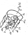
本発明に係るケーブル案内装置1(図1〜図3)は、それぞれ両端面で開口した多数の連結輪体2を備え、各連結輪体は互いに枢動可能に連結されて相対的に少なくとも2方向に屈曲可能である(図1、図2参照)。本実施形態によれば、各連結輪体はそれぞれ回転対称形状の輪郭をもつ外囲部を備えている。径方向外側に設けられている案内要素3が案内通路4の外縁を画定し、この場合、案内通路の外縁はほぼ完全に閉じられている。本実施形態によれば、これらの案内要素によって連結状態の連結輪体全長に亘って延在する複数の回転対称形状体の複数セクションが形成されている。隣接する各案内要素3は連結状態の連結輪体全長にわたって延在するように設けられたスリット状開口部5によって切れ目を入れられており、これらのスリット状開口部を介してケーブル線路等を案内通路内に導入取出可能となっている。この場合、各連結輪体は、或る選ばれたケーブル案内装置の配列状態、例えばケーブル案内装置が伸長状態にあるときに、隣接する連結輪体同士のスリット状開口部が相互に連絡し合うように組み合わされており、従ってケーブル案内装置全長に亘って連続的なスリット状開口部が形成されている(図3a)。
The cable guide device 1 (FIGS. 1 to 3) according to the present invention includes a large number of connecting
各連結輪体の関節ジョイントはジョイント要素6、7によって形成され、これらのジョイント要素は、各関節ジョイントの連結を形成又は解除するためにそれぞれ互いに結合又は分離すべき連結輪体2同士をケーブル案内装置の伸長状態における長手軸線9に対して予め定められた範囲内の或る角度をなす方向8に相対移動させたときに互いに結合又は分離できるように構成されている。この実施形態によれば、この目的で隣接連結輪体同士は約75°の角度で接近離反できるようになっており、この動きは連結輪体相互の旋回運動によって助勢でき、或いは係る旋回運動と重ね合せることもできる。分離の開始時及び/又は結合過程の終了時には、隣接する連結輪体同士及びジョイント要素同士を互いにケーブル案内装置の長手軸線9に対してほぼ90°の角度で相対運動させる。
Articulation joint of each connecting wheel unit is formed by a
本実施形態におけるジョイント要素6、7は、互いに対応した形状のジョイント本体とその受容部、即ちジョイント球体とボールソケットで構成されている。ボールソケットの受容穴10は縦向きのジョイント軸線11をもち、これは受容穴の内部に配置されるジョイント球体の中立位置における軸線と一致し、ジョイント球体は係着領域12を有している。従って受容部のジョイント軸線11は、同様に基準状態においてケーブル案内装置の長手軸線9に対して或る角度、本実施形態では90°の角度をなすようになっている。ジョイント本体受容部、即ちボールソケットの開口端面部を斜めに傾けてあるので、対応するジョイント要素、即ちジョイント球体の係着領域は、ケーブル案内装置の長手方向に張力又はスラスト力が加わったときにケーブル案内装置の長手軸線を含む面内で該ジョイント球体を全周で取り囲む受容部のハウジング13に当接する。これにより、ケーブル案内装置の長手方向に作用する大きな張力又はスラスト力を係る構成の関節ジョイントによって吸収することができる。尚、このようなボールソケットとジョイント球体の傾斜或いは別形式のジョイント要素が図示の直角配置とは異なった場合にも同様のことが言える。
The
本実施形態において、ボール形式のジョイント要素6のジョイント軸線6aは該ジョイント要素のボール中心点及び係着領域12を通っており、同様にケーブル案内装置の長手軸線9に対して直交している。勿論、場合によってジョイント本体6と受容穴10のジョイント軸線間の角度は、それらがケーブル案内装置の長手軸線9との間になす角度と相互に異なっていてもよい。
In this embodiment, the joint axis 6a of the ball-type
ボール形式のジョイント要素6とボールソケット形式のジョイント要素7は、それぞれ支持体としての台座16上のウエブ状部分に設けられており、この台座16はケーブル案内装置のほぼ全周に亘って延在する案内要素3を担持している。この場合、ウエブ状部分15a、15b(図3d)はケーブル案内装置の長手軸線9に対して直交する方向で相互にずらして配置されている。それとともにウエブ状部分15a、15bとボールソケット及びジョイント球体の端部とによってほぼZ字形の互いに背後から係合する一対のジョイント要素、即ち大きな張力を吸収することが可能なジョイント要素が形成されている。勿論、本発明はこれに限定されるものではなく、これとは別形式のジョイント要素、例えば好適に配置されたピン形式のジョイント要素と対応する受容部とによっても、同様の効果を実現することができる。
The ball-type
本実施形態によれば、ジョイント要素6、7はスナップ嵌合方式で結合される。連結輪体同士の分離を容易とするために受容部穴10の開口周縁を囲んで凹部17が設けられており、この凹部はここでは環状溝として形成され、受容穴の開口18と同方向に向かって開口している。
According to this embodiment, the
台座16には、ケーブル線路その他のデバイス、例えば複数の連結輪体に亘って敷設されるばね棒等を収容する開口部19がジョイント要素6、7の下部に設けられ、更にその下方に別の開口部20が設けられている。これら全ての開口部19、20は、ケーブル案内装置が伸長状態にあるときは互いに一列に整列される。尚、この実施形態では開口部19、20が全周で閉じているが、それぞれ個別に横方向に開いていてもよい。
The
関節ジョイントの連結を容易とするために、台座16には結合・分離方向と交差する方向に延在するウエブ状の案内壁21が設けられている。従って、連結輪体を組み立てる際にジョイント球体6を案内壁21の受容穴10側の表面上で粗く概略に位置決めし、次いで受容穴10内にスナップ嵌めすることができる。この結合の途中では、ジョイント球体6が開口部19を部分的又は完全に覆い隠すことになる。従って、ケーブル案内装置が連結された後はケーブル線路その他のデバイスを開口部19、20に通すことができ、この場合、挿入したケーブル線路その他のデバイスにケーブル案内装置長手方向の張力が作用することはなく、換言すれば挿入したケーブル線路その他のデバイスは係る張力を吸収する必要がない。
In order to facilitate the connection of the joint joint, the
連結輪体同士の分離を容易とするために、ボールソケット形式のジョイント要素7はスリット状の工具導入穴22を備えており、この工具導入穴の中にケーブル案内装置の外部からねじ回しのような工具を挿入し、受容穴に嵌合しているジョイント球体を押し下げてジョイント要素間の連結を分離させることができる。この目的で、工具の挿入位置に対応する箇所で各案内要素3に閉鎖可能な開口部や破断可能部を備えた閉鎖部などを設けてもよく、或いは同様の箇所で隣接する案内要素の間の部分を外部に開放露呈させた構造としてもよい。場合によってはスリット状開口部5から工具を挿入することも可能である。この場合、工具導入22は肩部23を有することが好ましく、この肩部に工具をレバー形式に当接位置決めしてジョイント球体6のほぼ頂点を工具によりてこの原理で押し下げることができるようにしておくとよい。
In order to facilitate the separation of the connecting ring bodies, the ball socket type
各連結輪体は連結状態でほぼ全周で閉じた筒状セクションを形成する(図3a参照)。この目的で各連結輪体は両端部で互いに重なり合う回転対称形状の外囲部25を有し、この外囲部はケーブル案内装置の全周を囲んで延在する球面裁頭カップ状セクションの形態に構成されている。個々の連結輪体における両端部の球面裁頭カップ状セクションの間には筒状中間セクションを設けてもよい。この場合でも両端部は隣接する連結輪体の端部と重なり合うようにする。ジョイント要素6、7は軸線方向でカップ状セクションの端面から突出している。これとは無関係に、ジョイント要素6、7のジョイント軸線6a、11はケーブル案内装置の長手方向に関して球面裁頭カップ状セクションの曲率中心を通る位置、即ち球面裁頭カップ状セクションの最大径部分を通る位置にある。全体として、複数の案内要素3はスリット状開口部5を除いてケーブル案内装置の全周に亘って延在する。勿論、場合によってはスリット状開口部は図示の実施形態よりも大きな幅寸法であってもよい。ジョイント軸線の周りの連結輪体間の屈曲運動が可能である限り、連結輪体の端部形状を図示の実施形態と異なる別形状としてもよい。
Each connecting ring body forms a cylindrical section that is closed in substantially the entire circumference in a connected state (see FIG. 3a). For this purpose, each connecting wheel has a rotationally symmetrical
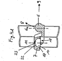
図4及び図5に示す第2実施形態は図1〜図3の第1実施形態の変更例であり、同一又は同効部分には同じ符号を付してある。この変形実施形態における相違点は、ジョイント要素が案内要素に結合されている点にある。 The second embodiment shown in FIGS. 4 and 5 is a modification of the first embodiment shown in FIGS. 1 to 3, and the same or equivalent parts are denoted by the same reference numerals. The difference in this variant embodiment is that the joint element is connected to the guide element.
この変形実施形態によれば、第1実施形態のジョイント要素と同様に構成されたジョイント要素6、7が少なくとも1つの梁部材30によって径方向外側の案内要素3に結合されている。この場合、互いに反対向きに配置された両梁部材30は連結輪体の結合・分離方向8と交差する向きに配置され、ここでは連結輪体に対して垂直に一体化されている。連結輪体の内部には両梁部材によって2つの案内通路4aが形成されている。各梁部材30は開口部31を備え、この開口部にケーブル線路その他のデバイス、例えば前述のばね棒等を選択的に通すことが可能である。各梁部材30は径方向外側へ向かって先細形状となっている。
According to this variant embodiment,
各梁部材30は、本実施形態によれば、図1〜図3に示した台座16と同様に大略又はほ完全に連結輪体2の一方のみの球面裁頭カップ状セクションに固定されている。場合によっては、連結輪体の長さを大きくするための筒状中間セクションを両端部の球面裁頭カップ状セクションの間に設けもよい。
According to this embodiment, each
互いに枢動可能に連結された連結輪体2同士の屈曲回動量を制限する目的で、案内要素3の外面或いは端面を止め部3aとして機能させることができる。場合によっては、台座16の一部を止め部として利用することもでき、特に2つ以上の梁部材が設けられている場合は、これら梁部材30の案内要素3に隣接する部分も止め部として利用することができる。
The outer surface or end surface of the
1 :ケーブル案内装置
2 :連結輪体
3 :案内要素
3a:止め部
4、4a:案内通路
5 :スリット状開口部
6 :ジョイント要素(ボール)
6a:ジョイント軸線
7 :ジョイント要素(ソケット)
8 :傾斜角度方向
9 :ケーブル案内装置長手軸線
10 :受容穴
11 :ジョイント軸線
12 :係着領域
13 :受容部ハウジング
15 :ウエブ状部分
16 :台座
17 :凹部
18 :受容穴開口
19 :開口部
20 :開口部
21 :案内壁部
22 :工具導入穴
23 :肩部
25 :外囲部
30 :梁部材
31 :開口部
DESCRIPTION OF SYMBOLS 1: Cable guide apparatus 2: Linking ring body 3: Guide element 3a: Stop part 4, 4a: Guide passage 5: Slit-shaped opening part 6: Joint element (ball)
6a: Joint axis 7: Joint element (socket)
8: Inclination angle direction 9: Cable guide device longitudinal axis 10: Receiving hole 11: Joint axis 12: Engagement region 13: Receiving portion housing 15: Web-shaped portion 16: Base 17: Recessed portion 18: Receiving hole opening 19: Opening portion 20: Opening part 21: Guide wall part 22: Tool introduction hole 23: Shoulder part 25: Outer part 30: Beam member 31: Opening part
Claims (17)
少なくとも1つの関節ジョイントを構成する対構成のジョイント要素(6、7)が、関節ジョイントの連結を形成又は解除するためにそれぞれ互いに結合又は分離すべき連結輪体(2)同士をケーブル案内装置の長手軸線(9)に対して予め定められた範囲内の角度をなす方向(8)に相対移動させたときに互いに結合又は分離できるように構成されていることを特徴とするケーブル案内装置。A cable guide device having a plurality of connecting ring bodies that are open at both end faces and are pivotally connected to each other and are relatively bendable in at least two directions, each connecting ring body being a longitudinal direction of the cable guide device At least one guide passage is formed by guide elements arranged at the front and back of each other and arranged radially outward, and the connecting ring bodies connected to each other in a pivotable manner inside the cable guide device. articulation joint is configured to absorb tension between, even in the connecting wheel bodies in those joint elements corresponding pairs constituted respectively is provided for forming the articulated joint,
At least one joint element pair configuration which constitutes the articulation joint (6,7) are connected to be coupled or separated from each other in order to form or release a connection of the articulation joint Watai (2) between the cable guide device A cable guide device configured to be coupled or separated from each other when moved relative to each other in a direction (8) forming an angle within a predetermined range with respect to the longitudinal axis (9).
Applications Claiming Priority (2)
| Application Number | Priority Date | Filing Date | Title |
|---|---|---|---|
| DE20305679U DE20305679U1 (en) | 2003-04-07 | 2003-04-07 | cable management |
| PCT/DE2004/000721 WO2004093279A1 (en) | 2003-04-07 | 2004-04-02 | Cable-routing device |
Publications (2)
| Publication Number | Publication Date |
|---|---|
| JP2006522576A JP2006522576A (en) | 2006-09-28 |
| JP4154438B2 true JP4154438B2 (en) | 2008-09-24 |
Family
ID=7981400
Family Applications (1)
| Application Number | Title | Priority Date | Filing Date |
|---|---|---|---|
| JP2006504291A Expired - Lifetime JP4154438B2 (en) | 2003-04-07 | 2004-04-02 | Cable guide device |
Country Status (9)
| Country | Link |
|---|---|
| US (2) | US7439446B2 (en) |
| EP (1) | EP1616376B1 (en) |
| JP (1) | JP4154438B2 (en) |
| KR (1) | KR100851259B1 (en) |
| CN (1) | CN100502183C (en) |
| BR (1) | BRPI0409089A (en) |
| DE (2) | DE20305679U1 (en) |
| TW (1) | TWI255316B (en) |
| WO (1) | WO2004093279A1 (en) |
Families Citing this family (39)
| Publication number | Priority date | Publication date | Assignee | Title |
|---|---|---|---|---|
| DE20305679U1 (en) * | 2003-04-07 | 2003-06-18 | Igus Gmbh | cable management |
| WO2009050781A1 (en) * | 2007-10-16 | 2009-04-23 | Mitsubishi Heavy Industries, Ltd. | Connector terminal protection cap and harness assembly |
| GB0807626D0 (en) * | 2008-04-25 | 2008-06-04 | Ultra Electronics Ltd | Routing of cables |
| US9763861B2 (en) | 2008-12-04 | 2017-09-19 | International Flavors & Fragrances Inc. | Stable, flowable silica capsule formulation |
| DE202009005546U1 (en) * | 2009-04-16 | 2009-06-18 | Igus Gmbh | cable management |
| DE202009005650U1 (en) * | 2009-04-17 | 2009-07-02 | Igus Gmbh | Power supply chain |
| DE102009029957B4 (en) * | 2009-06-19 | 2011-12-22 | Maximilian Rüttiger | Coupling chain link of a cable guide chain |
| DE102010032921A1 (en) * | 2010-07-30 | 2012-04-19 | Kabelschlepp Gmbh | Cable guide device with a ball-cable connection |
| DE102010032920C5 (en) | 2010-07-30 | 2023-03-02 | Tsubaki Kabelschlepp GmbH | Spatially deflectable cable routing device with bend radius limiters |
| US8297560B2 (en) * | 2010-08-10 | 2012-10-30 | Modernsolid Industrial Co., Ltd. | Line-management assembly |
| CN108465446A (en) | 2011-03-18 | 2018-08-31 | 国际香料和香精公司 | The microcapsules and preparation method thereof prepared by sol-gel precursors mixture |
| DE102011108849A1 (en) * | 2011-07-31 | 2013-01-31 | Maximilian Rüttiger | Linked chain link for energy guide chain, has connectors that are provided for connecting chain link main portion and are provided with positioning element for automatic supporting and feeding of connectors into operating positions |
| CN103062589A (en) * | 2011-10-21 | 2013-04-24 | 鸿富锦精密工业(深圳)有限公司 | Supporting device |
| DE202012001760U1 (en) | 2012-02-23 | 2012-05-30 | Igus Gmbh | cable management |
| DE102012015546A1 (en) * | 2012-08-08 | 2014-02-13 | Horst Meyer | umbilical cord |
| US20140238718A1 (en) * | 2013-02-25 | 2014-08-28 | General Cable Technologies Corporation | Protective armor for cabling |
| US9484724B2 (en) * | 2013-03-22 | 2016-11-01 | Michael Pecoraro | Cable protection device and system |
| DE202013101460U1 (en) * | 2013-04-05 | 2013-04-22 | Igus Gmbh | Cable routing from multiaxial bendable links |
| DE202013101992U1 (en) | 2013-05-08 | 2013-06-25 | Igus Gmbh | Cable routing with multiaxial bendable links |
| DE102015200665A1 (en) * | 2015-01-16 | 2016-07-21 | Deckel Maho Pfronten Gmbh | Processing unit for a machine tool and such a machine tool |
| DE102015110162B4 (en) | 2015-06-24 | 2017-05-11 | Industreer Gmbh | Energy guiding chain comprising a separate spring element inserted between the links, which biases the adjacent links in a preferred orientation |
| EP3365715B1 (en) | 2015-10-19 | 2020-12-02 | Commscope Technologies LLC | Articulating optical fiber guide system |
| CN106207905A (en) * | 2016-08-07 | 2016-12-07 | 艾和美 | A kind of for secretly burying conduit assembly within the walls |
| ES1170483Y (en) * | 2016-11-07 | 2017-02-13 | Unex Aparellaje Electrico Sl | "Articulated guide for cables" |
| DE202017102310U1 (en) | 2017-04-19 | 2017-08-11 | Igus Gmbh | Magazine device for cables and cable routing devices |
| CN107053258A (en) * | 2017-05-26 | 2017-08-18 | 绵阳伦奇机器人有限公司 | A kind of articulated structure of drag chain |
| US9972984B1 (en) | 2017-06-07 | 2018-05-15 | Custom Plastics, Inc. | Cable management assembly |
| DE102017118245A1 (en) | 2017-08-10 | 2019-02-14 | Murrplastik Systemtechnik Gmbh | GUIDE TUBE |
| JP6739105B2 (en) * | 2017-11-06 | 2020-08-12 | 株式会社国盛化学 | Cable protector |
| DE202018102239U1 (en) | 2018-04-21 | 2019-05-23 | Igus Gmbh | Energy guiding chain with wear detection |
| DE202018103418U1 (en) * | 2018-06-18 | 2018-12-19 | Igus Gmbh | Cable routing device for suspended applications, in particular as a service loop for a drilling rig |
| DE202018106543U1 (en) | 2018-11-19 | 2019-12-20 | Igus Gmbh | System for line monitoring in a line routing device, in particular in an energy chain |
| DE202019105125U1 (en) | 2019-09-16 | 2020-10-21 | Igus Gmbh | Rotary guide for one or more lines |
| DE202020106401U1 (en) | 2020-11-06 | 2021-12-07 | Igus Gmbh | Dispensing device for a flexible line arrangement and line guiding device with conveyor unit |
| DE202021100995U1 (en) | 2021-02-26 | 2022-05-30 | Igus Gmbh | Spatially deflectable line guiding device, in particular for a robot |
| DE202021101964U1 (en) | 2021-04-12 | 2022-07-18 | Igus Gmbh | System for monitoring the condition of a cable in an energy chain |
| JP2024513382A (en) | 2021-04-12 | 2024-03-25 | イグス ゲゼルシャフト ミット ベシュレンクター ハフトゥング | System for monitoring line conditions in energy chains |
| DE202021106364U1 (en) | 2021-11-23 | 2022-07-26 | Igus Gmbh | System for monitoring the condition of a cable in an energy chain |
| DE202022103458U1 (en) | 2022-06-21 | 2023-09-26 | Igus Gmbh | Energy chain with pull rope detector arrangement |
Family Cites Families (11)
| Publication number | Priority date | Publication date | Assignee | Title |
|---|---|---|---|---|
| IT208046Z2 (en) * | 1986-09-15 | 1988-03-31 | Tecno Mobili E Forniture Per A | FLEXIBLE CABLE ORGAN WITH BIDIRECTIONAL JOINTS. |
| US4771500A (en) * | 1987-04-09 | 1988-09-20 | Kovacs Julius S | Plumbers snake |
| DE9017373U1 (en) | 1990-12-22 | 1991-04-18 | Lic Langmatz Gmbh, 8100 Garmisch-Partenkirchen, De | |
| US5824957A (en) * | 1991-09-03 | 1998-10-20 | Technology Finance Corporation (Proprietary) Limited | Electrical cable containment |
| US5449206A (en) * | 1994-01-04 | 1995-09-12 | Lockwood Products, Inc. | Ball and socket joint with internal stop |
| US5942729A (en) * | 1997-08-04 | 1999-08-24 | The Siemon Company | Double hinged raceway |
| DE10030985B4 (en) * | 2000-06-30 | 2004-02-19 | Igus Spritzgussteile für die Industrie GmbH | Cable guide |
| DE10216081B4 (en) * | 2002-04-11 | 2005-03-31 | Kabelschlepp Gmbh | Robot with a routing device |
| DE20305679U1 (en) * | 2003-04-07 | 2003-06-18 | Igus Gmbh | cable management |
| WO2005076901A2 (en) * | 2004-02-06 | 2005-08-25 | Lynx, Inc. | Connection for beads with locked and articulating engagement |
| DE102004048640A1 (en) * | 2004-10-04 | 2006-04-06 | Otmar Fahrion | Chain |
-
2003
- 2003-04-07 DE DE20305679U patent/DE20305679U1/en not_active Expired - Lifetime
-
2004
- 2004-04-02 DE DE502004001683T patent/DE502004001683D1/en not_active Expired - Lifetime
- 2004-04-02 JP JP2006504291A patent/JP4154438B2/en not_active Expired - Lifetime
- 2004-04-02 US US10/552,427 patent/US7439446B2/en not_active Expired - Lifetime
- 2004-04-02 BR BRPI0409089-6A patent/BRPI0409089A/en active IP Right Grant
- 2004-04-02 WO PCT/DE2004/000721 patent/WO2004093279A1/en active IP Right Grant
- 2004-04-02 EP EP04725282A patent/EP1616376B1/en not_active Expired - Lifetime
- 2004-04-02 KR KR1020057019183A patent/KR100851259B1/en active IP Right Grant
- 2004-04-02 CN CNB2004800119918A patent/CN100502183C/en not_active Expired - Lifetime
- 2004-04-07 TW TW093109542A patent/TWI255316B/en active
-
2008
- 2008-10-07 US US12/246,884 patent/US7584597B2/en active Active
Also Published As
| Publication number | Publication date |
|---|---|
| US20060260833A1 (en) | 2006-11-23 |
| DE20305679U1 (en) | 2003-06-18 |
| US20090025361A1 (en) | 2009-01-29 |
| BRPI0409089A (en) | 2006-04-11 |
| EP1616376A1 (en) | 2006-01-18 |
| EP1616376B1 (en) | 2006-10-04 |
| TWI255316B (en) | 2006-05-21 |
| KR20060008874A (en) | 2006-01-27 |
| KR100851259B1 (en) | 2008-08-08 |
| US7439446B2 (en) | 2008-10-21 |
| CN100502183C (en) | 2009-06-17 |
| WO2004093279A1 (en) | 2004-10-28 |
| JP2006522576A (en) | 2006-09-28 |
| CN1784816A (en) | 2006-06-07 |
| DE502004001683D1 (en) | 2006-11-16 |
| US7584597B2 (en) | 2009-09-08 |
| TW200426313A (en) | 2004-12-01 |
Similar Documents
| Publication | Publication Date | Title |
|---|---|---|
| JP4154438B2 (en) | Cable guide device | |
| JP5331937B2 (en) | Cable guide | |
| JP4937248B2 (en) | A mechanism to hold, latch and lock the ball using radial and axial springs | |
| CA2679533C (en) | A multi-linked device having a reinforcing member | |
| US8450645B2 (en) | Flexible guide device for a welding rod | |
| US20120326440A1 (en) | Pipe coupling for connecting two pipe ends | |
| CN102906482B (en) | Element and connecting structure is cut for connecting structure | |
| CN104010773A (en) | Highly Articulated Probes With Anti-Twist Link Arrangement, Methods Of Formation Thereof, And Methods Of Performing Medical Procedures | |
| JPH10155226A (en) | Submarine cable protection device | |
| JP2003240174A (en) | Pipe universal joint | |
| CN104565627A (en) | Swivel joint of a fluid line, double swivel joint and water gun comprising the joint and the double joint | |
| BRPI0409089B1 (en) | CABLE DUCTING | |
| JPH0349884A (en) | Connection structure for in-pipe moving robot | |
| US10434664B2 (en) | Lamellar covers for use with articulating joints | |
| KR101716034B1 (en) | Connecting device of tent pole | |
| JPH0473540B2 (en) | ||
| JPS62193743A (en) | Flexible support member such as cable or the like | |
| KR20230172216A (en) | Prefabricated articular toy | |
| JP2001074171A (en) | Wiring-piping holding device | |
| JP2697758B2 (en) | Connection structure of propulsion body for propulsion method | |
| JP2719284B2 (en) | Propulsion pipe for propulsion method | |
| JP2533407B2 (en) | Flexible joint device | |
| SU1668759A1 (en) | Articulated joint | |
| KR20030073638A (en) | Device to join protection pad for structure | |
| KR20190105386A (en) | Device for connecting rope |
Legal Events
| Date | Code | Title | Description |
|---|---|---|---|
| A131 | Notification of reasons for refusal |
Free format text: JAPANESE INTERMEDIATE CODE: A131 Effective date: 20071107 |
|
| A601 | Written request for extension of time |
Free format text: JAPANESE INTERMEDIATE CODE: A601 Effective date: 20080205 |
|
| A602 | Written permission of extension of time |
Free format text: JAPANESE INTERMEDIATE CODE: A602 Effective date: 20080219 |
|
| A601 | Written request for extension of time |
Free format text: JAPANESE INTERMEDIATE CODE: A601 Effective date: 20080307 |
|
| A602 | Written permission of extension of time |
Free format text: JAPANESE INTERMEDIATE CODE: A602 Effective date: 20080319 |
|
| A601 | Written request for extension of time |
Free format text: JAPANESE INTERMEDIATE CODE: A601 Effective date: 20080407 |
|
| A602 | Written permission of extension of time |
Free format text: JAPANESE INTERMEDIATE CODE: A602 Effective date: 20080424 |
|
| A521 | Request for written amendment filed |
Free format text: JAPANESE INTERMEDIATE CODE: A523 Effective date: 20080507 |
|
| TRDD | Decision of grant or rejection written | ||
| A01 | Written decision to grant a patent or to grant a registration (utility model) |
Free format text: JAPANESE INTERMEDIATE CODE: A01 Effective date: 20080618 |
|
| A01 | Written decision to grant a patent or to grant a registration (utility model) |
Free format text: JAPANESE INTERMEDIATE CODE: A01 |
|
| A61 | First payment of annual fees (during grant procedure) |
Free format text: JAPANESE INTERMEDIATE CODE: A61 Effective date: 20080707 |
|
| R150 | Certificate of patent or registration of utility model |
Free format text: JAPANESE INTERMEDIATE CODE: R150 Ref document number: 4154438 Country of ref document: JP Free format text: JAPANESE INTERMEDIATE CODE: R150 |
|
| FPAY | Renewal fee payment (event date is renewal date of database) |
Free format text: PAYMENT UNTIL: 20110711 Year of fee payment: 3 |
|
| FPAY | Renewal fee payment (event date is renewal date of database) |
Free format text: PAYMENT UNTIL: 20110711 Year of fee payment: 3 |
|
| FPAY | Renewal fee payment (event date is renewal date of database) |
Free format text: PAYMENT UNTIL: 20120711 Year of fee payment: 4 |
|
| R250 | Receipt of annual fees |
Free format text: JAPANESE INTERMEDIATE CODE: R250 |
|
| FPAY | Renewal fee payment (event date is renewal date of database) |
Free format text: PAYMENT UNTIL: 20130711 Year of fee payment: 5 |
|
| R250 | Receipt of annual fees |
Free format text: JAPANESE INTERMEDIATE CODE: R250 |
|
| R250 | Receipt of annual fees |
Free format text: JAPANESE INTERMEDIATE CODE: R250 |
|
| R250 | Receipt of annual fees |
Free format text: JAPANESE INTERMEDIATE CODE: R250 |
|
| R250 | Receipt of annual fees |
Free format text: JAPANESE INTERMEDIATE CODE: R250 |
|
| R250 | Receipt of annual fees |
Free format text: JAPANESE INTERMEDIATE CODE: R250 |
|
| R250 | Receipt of annual fees |
Free format text: JAPANESE INTERMEDIATE CODE: R250 |
|
| R250 | Receipt of annual fees |
Free format text: JAPANESE INTERMEDIATE CODE: R250 |
|
| R250 | Receipt of annual fees |
Free format text: JAPANESE INTERMEDIATE CODE: R250 |
|
| R250 | Receipt of annual fees |
Free format text: JAPANESE INTERMEDIATE CODE: R250 |
|
| R250 | Receipt of annual fees |
Free format text: JAPANESE INTERMEDIATE CODE: R250 |
|
| R250 | Receipt of annual fees |
Free format text: JAPANESE INTERMEDIATE CODE: R250 |
|
| R250 | Receipt of annual fees |
Free format text: JAPANESE INTERMEDIATE CODE: R250 |