JP4937248B2 - A mechanism to hold, latch and lock the ball using radial and axial springs - Google Patents
A mechanism to hold, latch and lock the ball using radial and axial springs Download PDFInfo
- Publication number
- JP4937248B2 JP4937248B2 JP2008505396A JP2008505396A JP4937248B2 JP 4937248 B2 JP4937248 B2 JP 4937248B2 JP 2008505396 A JP2008505396 A JP 2008505396A JP 2008505396 A JP2008505396 A JP 2008505396A JP 4937248 B2 JP4937248 B2 JP 4937248B2
- Authority
- JP
- Japan
- Prior art keywords
- ball
- cavity
- groove
- housing
- disposed
- Prior art date
- Legal status (The legal status is an assumption and is not a legal conclusion. Google has not performed a legal analysis and makes no representation as to the accuracy of the status listed.)
- Expired - Fee Related
Links
- 230000037431 insertion Effects 0.000 claims 2
- 238000003780 insertion Methods 0.000 claims 2
- 239000000463 material Substances 0.000 description 2
- 238000012986 modification Methods 0.000 description 2
- 230000004048 modification Effects 0.000 description 2
- 238000010586 diagram Methods 0.000 description 1
- 230000014759 maintenance of location Effects 0.000 description 1
- 239000002184 metal Substances 0.000 description 1
- 238000000034 method Methods 0.000 description 1
- 230000000717 retained effect Effects 0.000 description 1
Images


Classifications
-
- F—MECHANICAL ENGINEERING; LIGHTING; HEATING; WEAPONS; BLASTING
- F16—ENGINEERING ELEMENTS AND UNITS; GENERAL MEASURES FOR PRODUCING AND MAINTAINING EFFECTIVE FUNCTIONING OF MACHINES OR INSTALLATIONS; THERMAL INSULATION IN GENERAL
- F16C—SHAFTS; FLEXIBLE SHAFTS; ELEMENTS OR CRANKSHAFT MECHANISMS; ROTARY BODIES OTHER THAN GEARING ELEMENTS; BEARINGS
- F16C11/00—Pivots; Pivotal connections
- F16C11/04—Pivotal connections
- F16C11/06—Ball-joints; Other joints having more than one degree of angular freedom, i.e. universal joints
- F16C11/0685—Manufacture of ball-joints and parts thereof, e.g. assembly of ball-joints
- F16C11/069—Manufacture of ball-joints and parts thereof, e.g. assembly of ball-joints with at least one separate part to retain the ball member in the socket; Quick-release systems
-
- F—MECHANICAL ENGINEERING; LIGHTING; HEATING; WEAPONS; BLASTING
- F16—ENGINEERING ELEMENTS AND UNITS; GENERAL MEASURES FOR PRODUCING AND MAINTAINING EFFECTIVE FUNCTIONING OF MACHINES OR INSTALLATIONS; THERMAL INSULATION IN GENERAL
- F16B—DEVICES FOR FASTENING OR SECURING CONSTRUCTIONAL ELEMENTS OR MACHINE PARTS TOGETHER, e.g. NAILS, BOLTS, CIRCLIPS, CLAMPS, CLIPS OR WEDGES; JOINTS OR JOINTING
- F16B21/00—Means for preventing relative axial movement of a pin, spigot, shaft or the like and a member surrounding it; Stud-and-socket releasable fastenings
- F16B21/06—Releasable fastening devices with snap-action
- F16B21/07—Releasable fastening devices with snap-action in which the socket has a resilient part
- F16B21/078—Releasable fastening devices with snap-action in which the socket has a resilient part the socket having a further molded-in or embedded component, e.g. a ring with snap-in teeth molded into it
-
- Y—GENERAL TAGGING OF NEW TECHNOLOGICAL DEVELOPMENTS; GENERAL TAGGING OF CROSS-SECTIONAL TECHNOLOGIES SPANNING OVER SEVERAL SECTIONS OF THE IPC; TECHNICAL SUBJECTS COVERED BY FORMER USPC CROSS-REFERENCE ART COLLECTIONS [XRACs] AND DIGESTS
- Y10—TECHNICAL SUBJECTS COVERED BY FORMER USPC
- Y10T—TECHNICAL SUBJECTS COVERED BY FORMER US CLASSIFICATION
- Y10T403/00—Joints and connections
- Y10T403/32—Articulated members
- Y10T403/32008—Plural distinct articulation axes
- Y10T403/32041—Universal
-
- Y—GENERAL TAGGING OF NEW TECHNOLOGICAL DEVELOPMENTS; GENERAL TAGGING OF CROSS-SECTIONAL TECHNOLOGIES SPANNING OVER SEVERAL SECTIONS OF THE IPC; TECHNICAL SUBJECTS COVERED BY FORMER USPC CROSS-REFERENCE ART COLLECTIONS [XRACs] AND DIGESTS
- Y10—TECHNICAL SUBJECTS COVERED BY FORMER USPC
- Y10T—TECHNICAL SUBJECTS COVERED BY FORMER US CLASSIFICATION
- Y10T403/00—Joints and connections
- Y10T403/32—Articulated members
- Y10T403/32606—Pivoted
- Y10T403/32631—Universal ball and socket
Landscapes
- Engineering & Computer Science (AREA)
- General Engineering & Computer Science (AREA)
- Mechanical Engineering (AREA)
- Snaps, Bayonet Connections, Set Pins, And Snap Rings (AREA)
- Pens And Brushes (AREA)
- Clamps And Clips (AREA)
- Pivots And Pivotal Connections (AREA)
- Mutual Connection Of Rods And Tubes (AREA)
Description
本発明は、全体として、構成要素を掛け止めすることに関し、より具体的には、回転運動及び円錐運動の双方を可能にすべく球形の構成要素を掛け止めすることに関する。 The present invention relates generally to latching components, and more specifically to latching spherical components to allow both rotational and conical motion.
傾斜コイルばねは、広範に、主として、長手方向の移動及び回転運動を必要とするコネクタにて、掛止め目的のため使用されている。当該出願は、ボールとソケット装置を有する掛止め機構にて傾斜コイルばねを利用することにより、その傾斜コイルばねの使用を更に拡大するものである。 Gradient coil springs are widely used primarily for latching purposes in connectors that require longitudinal movement and rotational movement. The application further expands the use of the canted coil spring by utilizing the canted coil spring in a latching mechanism having a ball and socket device.
保持用途にて使用されるコネクタは、例えば、バルセルズ(Balsells)及びその他の者への米国特許明細書4,974,821号、米国特許明細書5,139,276号、米国特許明細書5,082,390号、米国特許明細書5,545,842号、米国特許明細書5,411,348号に広く記載されている。これらの特許の全ては、参考として引用し本明細書に含められる。 Connectors used in retention applications are described, for example, in US Pat. No. 4,974,821, US Pat. No. 5,139,276, US Pat. No. 5,139,276 to Balsells and others. No. 082,390, US Pat. No. 5,545,842, US Pat. No. 5,411,348. All of these patents are incorporated herein by reference.
上記の引用した特許の内、米国特許明細書4,974,821号には、全体として、傾斜コイルばねと、溝とが記載されており、該溝は、ばねの荷重に応答して特定の予め選んだ特性を可能にすべく主軸線の半径方向に荷重をかけるよえにばねを配向する。 Of the above-cited patents, U.S. Pat. No. 4,974,821 generally describes a canted coil spring and a groove that is responsive to a spring load. Orient the spring before applying a load in the radial direction of the main axis to allow preselected characteristics.
米国特許明細書5,082,390号には、第一及び第二の部材を互いに保持し且つ係止する傾斜コイルばねが教示されている。
米国特許明細書5,139,276号には、ばねの弾性的特性を制御すべく溝内にて半径方向に荷重が加えられたばねが開示されている。
U.S. Pat. No. 5,082,390 teaches a canted coil spring that holds and locks the first and second members together.
U.S. Pat. No. 5,139,276 discloses a spring loaded radially in a groove to control the elastic properties of the spring.
米国特許明細書5,411,348号及び米国特許明細書5,545,842号には、2つの部材を互いに好ましいように係止するばね機構が教示されている。 U.S. Pat. No. 5,411,348 and U.S. Pat. No. 5,545,842 teach a spring mechanism that favorably locks two members together.
引用した文献又は先行技術の何れもボールの円錐動作を可能にするものはない。 None of the cited literature or prior art allows for the conical motion of the ball.
本発明に従った掛止め機構は、全体として、開口部が形成されたキャビティを有するハウジングを含む。開口部を通してハウジングキャビティ内に挿入し得る寸法とされたボールは、軸部を有しており、該軸部は、該軸部がそこから伸びるボールよりも小径である。 The latching mechanism according to the present invention generally includes a housing having a cavity in which an opening is formed. A ball that is dimensioned to be inserted through the opening into the housing cavity has a shaft that is smaller in diameter than the ball from which the shaft extends.
ハウジングキャビティ内に少なくとも1つの溝がキャビティの開口部に近接して設けられ、また、コイルばねが溝内に設けられており、該コイルばねは、軸部がハウジングの中心線に対して選んだ円錐角度にある状態にて、ボールをキャビティから回転可能に保持する。 At least one groove is provided in the housing cavity adjacent to the opening of the cavity, and a coil spring is provided in the groove, the coil spring having a shaft portion selected with respect to the center line of the housing. The ball is rotatably held from the cavity in a conical angle state.
1つの実施の形態において、溝は、周溝であり、また、コイルばねは、連続的なガータ型ばねである。別の実施の形態において、複数の円弧状溝がハウジングキャビティ内に設けられており、また、円弧状のコイルばねセグメントが円弧状溝の各々に配設されている。 In one embodiment, the groove is a circumferential groove and the coil spring is a continuous garter spring. In another embodiment, a plurality of arcuate grooves are provided in the housing cavity, and an arcuate coil spring segment is disposed in each arcuate groove.
複数の隔たった周溝をハウジングキャビティ内にて利用することができ、また、ボールをハウジング内にて異なる側方向位置に位置決めすることを可能にする連続的なガータコイルばねが溝の各々に配設されている。 Multiple spaced circumferential grooves are available in the housing cavity, and a continuous garter coil spring is provided in each of the grooves that allows the ball to be positioned at different lateral positions within the housing. Has been.
1つの実施の形態において、溝及びばねは、ボールをハウジングキャビティ内にて係止する形態とされており、また、本発明の更に別の実施の形態において、キャビティは球形である。この実施の形態において、2つの溝をその内部にコイルばねを有するハウジングキャビティ内に配設することができ、溝は、ボールの対向した半球上に配設される。 In one embodiment, the grooves and springs are configured to lock the ball within the housing cavity, and in yet another embodiment of the invention, the cavity is spherical. In this embodiment, two grooves can be disposed in a housing cavity having a coil spring therein, the grooves being disposed on opposite hemispheres of the ball.
本発明の有利な点及び特徴は、添付図面と共に検討したとき、以下の説明から一層良く理解されよう。
図1を参照すると、全体として、開口部16を有するキャビティ14を備えるハウジング12を含む、本発明に従った掛止め機構10が示されている。ボール22であって、該ボールから伸びる軸部24を有する上記ボールがキャビティ14内に配設されており、ボール22は、図示するように、開口部16を通してハウジングキャビティ14内に挿入し得る寸法とされている。半径方向傾斜コイルばね28がv字形溝30内に配設され、ボール22を、軸部が図1にて矢印34、36で示した選んだ円錐角度を有するようにキャビティ14内にて回転可能に保持する。特定の予め選んだ特徴を提供するのに適したばね及び溝は、その内容を参考として引用し本明細書に含めた上述の米国特許明細書に記載されている。
The advantages and features of the present invention will be better understood from the following description when considered in conjunction with the accompanying drawings.
Referring to FIG. 1, a latching mechanism 10 according to the present invention is shown that generally includes a
簡単に説明すれば、ばね28は、キャビティ30内に保持されており、半径方向力が短軸線40に沿ってコイルばね28に加えられる。ばね28は、最初、キャビティ14のID(内径)よりも大きいばねOD(外径)によりキャビティ内に保持され、これにより、ばねをキャビティ14内にて保持する力を発生させる。溝の幅(GW)は、ばねのコイル幅(CW)よりも大きい(GW>CW)。この型式の設計は、約1対1の接続対接続切離し比を生じさせる。本発明の一部と考えられるその他の形態は、上記に引用した米国特許明細書に記載されている。
Briefly, the
ボール22を挿入し且つボール22をハウジング12から切り離すのに必要な力は、接触角度による影響を受け、接触角度が大きければ大きい程、接続し又は接続切離しするのに必要な力は小さくなる。かかる接触角度は、溝の形態により決まる。
The force required to insert the
図2を参照すると、代替的な実施の形態46は、テーパー付き底部を含む異なる溝58の形態を利用して、その内部にボール52が挿入されたキャビティ50を有し、該ボールは伸びた軸部54を有する、ハウジング48を含む。底部における溝の幅は、溝のコイル幅よりも小さく、これは別の方法を示すものであり、ばね60を溝58及びキャビティ50内に保持することができ、この方法において、挿入し且つ接続を切り離す力は可変であり、接続し且つ接続を切り離しするためには、また、溝及びばねの組立体の幾何学的形態のため、より大きな力を必要とする。この場合にも、溝の形態に対するばねの更なる変更は、上述した米国特許明細書にて見ることができる。
Referring to FIG. 2, an
図3及び図4に示すように、コイルばね28は、円弧状セグメントからなり、また、これに相応して、溝30もまた円弧状セグメントとすることができ、一方、図4に示したように、コイルばね60は連続的とし、溝58がまた周溝であり且つキャビティ50内にて連続するものとすることができる。
As shown in FIGS. 3 and 4, the
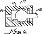
図5、図6、図7に示した実施の形態10、46及び70並びに図8に示した実施の形態72に対する構造の材料は、金属又は同様のもののような、適宜な剛性材料にて形成されたハウジング12、48、74、76を含み、このことはまた、ボール22、52、80、82に対しても当て嵌まる。
The structural material for the
図5、図6及び図7を特に参照すると、ハウジング72は、ばね98、100、102を支持するための3つの隔たった溝を含み、これにより、図5、図6、図7に順次に示したように、キャビティ86内にてボール80を側方向に位置決めすることを可能にするキャビティ86を備えている。接続し且つ接続を切り離す力を制御するため、色々なばね及び溝の形態を利用することができる。図5aに示したように、溝90及びばねの形態は、軸部を有するボール80が通過するのを可能にする一方、図7aに示した溝94及びばねの形態102は、ハウジングキャビティ86からの接続切離しを阻止し得るようボール80を係止する。
With particular reference to FIGS. 5, 6, and 7, the
図8に示した実施の形態72は、球形の内部形状部114を有するキャビティ110を利用し、その内部にばね122、124が配置された2つの溝118、120を更に含み、溝118及びばね122によりボール82により大きい保持力を提供し、この場合、溝120及びばね122は、ボール82の反対の又は対向する半球128、130上に配設される。
The
本発明を有益に使用することができる態様を示す目的のため、本発明により半径方向及び軸方向ばねを利用する特定のボールを保持し、掛止めし且つ係止する適用例について上記に説明したが、本発明はこれらにのみ限定されるものではないことを理解すべきである。すなわち、本発明は、上述した要素を適宜に備え、これら要素から成るものとし又はこれら要素から実質的に成るものとすることができる。更に、本明細書にて一例として開示された発明は、本明細書にて特に開示しない任意の要素が存在せずに実施することができる。従って、当該技術の当業者に案出されるであろう任意の及び全ての形態変更例、変更又は等価的な配置は、特許請求の範囲に規定されたように、本発明の範囲に属するとみなすべきである。 For purposes of illustrating the manner in which the present invention can be beneficially used, the above-described application for retaining, latching and locking specific balls utilizing radial and axial springs according to the present invention has been described. However, it should be understood that the present invention is not limited to these examples. That is, the present invention appropriately includes the above-described elements, can be composed of these elements, or can be substantially composed of these elements. Furthermore, the invention disclosed herein as an example can be practiced without the presence of any elements not specifically disclosed herein. Accordingly, any and all modifications, variations, or equivalent arrangements that may be devised by those skilled in the art are deemed to be within the scope of the present invention as defined in the claims. Should.
5Aは、ハウジングキャビティ内にて側方向への動きを可能にする特定の溝及びコイルばねの形態を示す図である。
7Aは、ボールをキャビティ内に係止してキャビティから除去されるのを阻止する溝及びばねの形態を示す図である。
Claims (11)
開口部を有するキャビティを含むハウジングと、
ボールであって、該ボールよりも小径で且つ該ボールから伸びる軸部を有し、前記開口部を通してハウジングキャビティ内に挿入し且つハウジングキャビティから接続切離しし得る寸法とされた前記ボールと、
キャビティ開口部に近接してハウジングキャビティ内にある少なくとも1つの溝と、
溝内に配設されたコイルばねであって、前記軸部がハウジングの中心線に対して選んだ円錐角度にある状態にてボールを前記キャビティ内で回転することを可能にし、ボールの挿入及び接続切離し力を制御し得るよう溝の形態により決定される、ボールに対する接触角度を有する、前記コイルばねとを備える、掛止め機構。In the latching mechanism,
A housing including a cavity having an opening;
A ball having a diameter smaller than the ball and extending from the ball, the ball being dimensioned to be inserted into the housing cavity through the opening and to be disconnected from the housing cavity;
At least one groove in the housing cavity proximate to the cavity opening;
A coil spring disposed in the groove, allowing the ball to rotate in the cavity with the shaft at a selected cone angle with respect to the centerline of the housing; A latching mechanism comprising the coil spring having a contact angle with the ball, which is determined by the shape of the groove so as to control the disconnection force.
開口部を有するキャビティを含むハウジングと、
ボールであって、該ボールよりも小径で且つ該ボールから伸びる軸部を有し、前記開口部を通してハウジングキャビティ内に挿入し且つハウジングキャビティから接続切離しし得る寸法とされた前記ボールと、
キャビティ開口部に近接してハウジングキャビティ内にある少なくとも1つの溝と、
溝内に配設されたコイルばねであって、ボールを前記キャビティ内で回転することを可能し、また、ボールの挿入及び除去力を制御し得るよう溝の形態により決定される、ボールに対する接触角度を有する、前記コイルばねとを備える、掛止め機構。In the latching mechanism,
A housing including a cavity having an opening;
A ball having a diameter smaller than the ball and extending from the ball, the ball being dimensioned to be inserted into the housing cavity through the opening and to be disconnected from the housing cavity;
At least one groove in the housing cavity proximate to the cavity opening;
A coil spring disposed in the groove, which allows the ball to rotate in the cavity and is determined by the shape of the groove so that the insertion and removal force of the ball can be controlled. A latching mechanism comprising the coil spring having an angle.
Applications Claiming Priority (5)
| Application Number | Priority Date | Filing Date | Title |
|---|---|---|---|
| US66830905P | 2005-04-05 | 2005-04-05 | |
| US60/668,309 | 2005-04-05 | ||
| US11/278,372 US20060228166A1 (en) | 2005-04-05 | 2006-03-31 | Ball holding, latching and locking applications using radial and axial springs |
| US11/278,372 | 2006-03-31 | ||
| PCT/US2006/012109 WO2006107789A2 (en) | 2005-04-05 | 2006-04-03 | Ball holding, latching and locking applications using radial and axial springs |
Publications (2)
| Publication Number | Publication Date |
|---|---|
| JP2008536066A JP2008536066A (en) | 2008-09-04 |
| JP4937248B2 true JP4937248B2 (en) | 2012-05-23 |
Family
ID=37073984
Family Applications (1)
| Application Number | Title | Priority Date | Filing Date |
|---|---|---|---|
| JP2008505396A Expired - Fee Related JP4937248B2 (en) | 2005-04-05 | 2006-04-03 | A mechanism to hold, latch and lock the ball using radial and axial springs |
Country Status (5)
| Country | Link |
|---|---|
| US (1) | US20060228166A1 (en) |
| EP (1) | EP1869332B1 (en) |
| JP (1) | JP4937248B2 (en) |
| DE (1) | DE602006011863D1 (en) |
| WO (1) | WO2006107789A2 (en) |
Cited By (1)
| Publication number | Priority date | Publication date | Assignee | Title |
|---|---|---|---|---|
| KR101995743B1 (en) * | 2018-02-12 | 2019-07-03 | 주식회사 센트랄 | Ball Joint Having Ring Temporary Mounting Groove |
Families Citing this family (18)
| Publication number | Priority date | Publication date | Assignee | Title |
|---|---|---|---|---|
| US9267526B2 (en) | 2003-06-04 | 2016-02-23 | Bal Seal Engineering, Inc. | Spring latching connectors |
| US7838787B2 (en) * | 2005-04-05 | 2010-11-23 | Bal Seal Engineering Co., Inc. | Ball holding, latching and locking applications using radial and axial springs by incorporating electrical conductivity and electrical switchings |
| WO2010014688A2 (en) * | 2008-07-30 | 2010-02-04 | Bal Seal Engineering | Canted coil multi-metallic wire |
| EP2334937B1 (en) * | 2008-09-15 | 2017-04-12 | Bal Seal Engineering, Inc. | Apparatus including a pin connector for securing a first member and a second member to one another, and associated methods |
| WO2011068769A1 (en) * | 2009-12-01 | 2011-06-09 | Illinois Tool Works Inc. | Panel connection snap assembly |
| US9004805B2 (en) | 2010-11-30 | 2015-04-14 | Bal Seal Engineering, Inc. | Multi-stage engagement assemblies and related methods |
| US9284970B2 (en) | 2012-09-14 | 2016-03-15 | Bal Seal Engineering, Inc. | Connector housings, use of, and method therefor |
| US9518626B2 (en) | 2012-11-13 | 2016-12-13 | Bal Seal Engineering, Inc. | Canted coil springs and assemblies and related methods |
| EP2971842B1 (en) | 2013-03-14 | 2019-07-10 | Bal Seal Engineering, Inc. | Canted coil spring with longitudinal component within and related methods |
| US10263368B2 (en) | 2013-06-25 | 2019-04-16 | Bal Seal Engineering, Inc. | Electrical contacts with electrically conductive springs |
| US10598241B2 (en) | 2014-02-26 | 2020-03-24 | Bal Seal Engineering, Inc. | Multi deflection canted coil springs and related methods |
| US10151368B2 (en) | 2014-05-02 | 2018-12-11 | Bal Seal Engineering, Inc. | Nested canted coil springs, applications thereof, and related methods |
| US10270198B2 (en) | 2014-09-15 | 2019-04-23 | Bal Seal Engineering, Inc. | Canted coil springs, connectors and related methods |
| US10520001B2 (en) | 2015-03-13 | 2019-12-31 | Bal Seal Engineering, Inc. | Stamped housings to facilitate assembly and related methods |
| US10181668B2 (en) | 2016-06-24 | 2019-01-15 | Bal Seal Engineering, Inc. | Spring contacts and related methods |
| US10900531B2 (en) | 2017-08-30 | 2021-01-26 | Bal Seal Engineering, Llc | Spring wire ends to faciliate welding |
| US20220047360A1 (en) * | 2018-09-10 | 2022-02-17 | Myung Heon Ha | Implant structure |
| DE102019215695A1 (en) * | 2019-10-11 | 2021-04-15 | Kennametal Inc. | Hydraulic tool holder and sealing piston for such |
Citations (3)
| Publication number | Priority date | Publication date | Assignee | Title |
|---|---|---|---|---|
| US4666330A (en) * | 1985-12-04 | 1987-05-19 | Tuthill Corporation | Ball joint assembly |
| JPH07174115A (en) * | 1993-10-26 | 1995-07-11 | Bal Seal Eng Co Inc | Assembling mechanism having environment-resistive sealing property, electromagnetic shielding property, conductivity and heat dissipating property |
| US6227751B1 (en) * | 1997-11-11 | 2001-05-08 | Mero Systeme Gmbh & Co. Kg | Mount for plate-shaped components |
Family Cites Families (23)
| Publication number | Priority date | Publication date | Assignee | Title |
|---|---|---|---|---|
| US2168339A (en) * | 1938-12-16 | 1939-08-08 | Curtis J Himel | Ant trap |
| CH239076A (en) * | 1942-05-15 | 1945-09-15 | Vialon Georges | Quick stapling device for a ball joint. |
| DE762762C (en) | 1942-12-22 | 1953-12-21 | Kaessbohrer Fahrzeug Karl | Ball joint |
| US2612139A (en) * | 1947-07-19 | 1952-09-30 | Collins William Joseph | Cat collar |
| US3272541A (en) * | 1954-06-10 | 1966-09-13 | Latzen Josef | Ball joints |
| US2856250A (en) * | 1957-02-13 | 1958-10-14 | Thoma Hans Johannes | Pistons and piston rods |
| US3186736A (en) * | 1962-10-02 | 1965-06-01 | Warshawsky Jerome | Limited universal swivel joint fittings for electric conduits |
| US3468527A (en) * | 1968-03-08 | 1969-09-23 | North American Rockwell | Coil spring |
| US3574363A (en) * | 1968-11-12 | 1971-04-13 | George T Stephenson | Locking device |
| US4037978A (en) * | 1974-08-23 | 1977-07-26 | B.C. Investments Ltd. | Resilient swivel connector |
| US4678210A (en) * | 1986-08-15 | 1987-07-07 | Peter J. Balsells | Loading and locking mechanism |
| US4974821A (en) * | 1988-04-25 | 1990-12-04 | Peter J. Balsells | Canted-coil spring with major axis radial loading |
| US5139276A (en) * | 1988-04-25 | 1992-08-18 | Peter J. Balsells | Canted coil spring radially loaded while in a cavity |
| US5080405A (en) * | 1990-07-10 | 1992-01-14 | Nitto Kohki Co., Ltd. | Corrugated pipe coupling |
| US5082390A (en) * | 1991-01-22 | 1992-01-21 | Peter J. Balsells | Latching, holding and locking spring apparatus |
| US5165375A (en) * | 1992-01-03 | 1992-11-24 | Jacobs Brake Technology Corporation | Master piston for a compression release engine retarder |
| CA2128453A1 (en) * | 1993-07-22 | 1995-01-23 | Garth B. Maughan | Ball and socket joint assembly |
| US5411348A (en) * | 1993-10-26 | 1995-05-02 | Bal Seal Engineering Company, Inc. | Spring mechanism to connect, lock and unlock, members |
| CH689389A5 (en) * | 1995-03-31 | 1999-03-31 | Ferag Ag | Suction device. |
| US6138475A (en) * | 1997-06-19 | 2000-10-31 | Kohl; Thomas D. | Jewelry retention system |
| DE19946578A1 (en) * | 1999-09-29 | 2001-04-05 | Hilti Ag | Quick connection system for threaded rods |
| WO2002070891A2 (en) * | 2001-03-05 | 2002-09-12 | Bal Seal Engineering Co. | Spring energized connector |
| WO2003071635A1 (en) * | 2002-02-15 | 2003-08-28 | Bal Seal Engineering Co., Inc. | Medically implantable electrical connector with constant conductivity |
-
2006
- 2006-03-31 US US11/278,372 patent/US20060228166A1/en not_active Abandoned
- 2006-04-03 WO PCT/US2006/012109 patent/WO2006107789A2/en active Application Filing
- 2006-04-03 EP EP06749088A patent/EP1869332B1/en not_active Expired - Fee Related
- 2006-04-03 DE DE602006011863T patent/DE602006011863D1/en active Active
- 2006-04-03 JP JP2008505396A patent/JP4937248B2/en not_active Expired - Fee Related
Patent Citations (3)
| Publication number | Priority date | Publication date | Assignee | Title |
|---|---|---|---|---|
| US4666330A (en) * | 1985-12-04 | 1987-05-19 | Tuthill Corporation | Ball joint assembly |
| JPH07174115A (en) * | 1993-10-26 | 1995-07-11 | Bal Seal Eng Co Inc | Assembling mechanism having environment-resistive sealing property, electromagnetic shielding property, conductivity and heat dissipating property |
| US6227751B1 (en) * | 1997-11-11 | 2001-05-08 | Mero Systeme Gmbh & Co. Kg | Mount for plate-shaped components |
Cited By (1)
| Publication number | Priority date | Publication date | Assignee | Title |
|---|---|---|---|---|
| KR101995743B1 (en) * | 2018-02-12 | 2019-07-03 | 주식회사 센트랄 | Ball Joint Having Ring Temporary Mounting Groove |
Also Published As
| Publication number | Publication date |
|---|---|
| EP1869332A4 (en) | 2008-05-14 |
| DE602006011863D1 (en) | 2010-03-11 |
| WO2006107789B1 (en) | 2007-07-05 |
| EP1869332B1 (en) | 2010-01-20 |
| US20060228166A1 (en) | 2006-10-12 |
| WO2006107789A3 (en) | 2007-05-24 |
| WO2006107789A2 (en) | 2006-10-12 |
| JP2008536066A (en) | 2008-09-04 |
| EP1869332A2 (en) | 2007-12-26 |
Similar Documents
| Publication | Publication Date | Title |
|---|---|---|
| JP4937248B2 (en) | A mechanism to hold, latch and lock the ball using radial and axial springs | |
| JP4154438B2 (en) | Cable guide device | |
| JP3781781B2 (en) | Lock mechanism | |
| KR100382978B1 (en) | Ball joint with ball holding part | |
| JP2004529292A (en) | Spring locking connector | |
| JP4861307B2 (en) | Suspension joints and bearings | |
| JP2005188645A (en) | Ball joint, and its bearing seat | |
| US2327951A (en) | Coupling device | |
| BRPI1004185A2 (en) | socket for ball joints and the like | |
| US5524987A (en) | Plugged slotted entry bearing | |
| US8641312B2 (en) | Rotating spigot for trusses | |
| JP2004239436A (en) | Counter raceway joint with improved cage | |
| US8794860B1 (en) | Rotational connector device | |
| BRPI0401102B1 (en) | universal joint and method of mounting a universal joint | |
| CN101151473A (en) | Ball holding, latching and locking applications using radial and axial springs | |
| CN208429198U (en) | Support construction and balance car | |
| JP2022105690A (en) | Lock mechanism for movable shaft, movable shaft and doll toy | |
| JP3135024U (en) | Movable joint components for small dolls | |
| US6871882B2 (en) | Ball-and-socket fluid coupling with primary and secondary retainer structures | |
| JP2009008193A (en) | Retainer of spherical roller bearing | |
| JPS587293B2 (en) | jinkounoudenojikuni kiguotorihazushijizaini renketsusultameno souchi | |
| JP4216672B2 (en) | Stop ring and fluid equipment with stop ring | |
| JP2004018026A (en) | Container coupler | |
| US20070054743A1 (en) | Transmission joint, in particular for transmitting drive between non-aligned shafts | |
| KR101716034B1 (en) | Connecting device of tent pole |
Legal Events
| Date | Code | Title | Description |
|---|---|---|---|
| A621 | Written request for application examination |
Free format text: JAPANESE INTERMEDIATE CODE: A621 Effective date: 20090309 |
|
| A131 | Notification of reasons for refusal |
Free format text: JAPANESE INTERMEDIATE CODE: A131 Effective date: 20110726 |
|
| RD04 | Notification of resignation of power of attorney |
Free format text: JAPANESE INTERMEDIATE CODE: A7424 Effective date: 20110913 |
|
| TRDD | Decision of grant or rejection written | ||
| A01 | Written decision to grant a patent or to grant a registration (utility model) |
Free format text: JAPANESE INTERMEDIATE CODE: A01 Effective date: 20120210 |
|
| A01 | Written decision to grant a patent or to grant a registration (utility model) |
Free format text: JAPANESE INTERMEDIATE CODE: A01 |
|
| A61 | First payment of annual fees (during grant procedure) |
Free format text: JAPANESE INTERMEDIATE CODE: A61 Effective date: 20120221 |
|
| FPAY | Renewal fee payment (event date is renewal date of database) |
Free format text: PAYMENT UNTIL: 20150302 Year of fee payment: 3 |
|
| R150 | Certificate of patent or registration of utility model |
Ref document number: 4937248 Country of ref document: JP Free format text: JAPANESE INTERMEDIATE CODE: R150 Free format text: JAPANESE INTERMEDIATE CODE: R150 |
|
| R250 | Receipt of annual fees |
Free format text: JAPANESE INTERMEDIATE CODE: R250 |
|
| R250 | Receipt of annual fees |
Free format text: JAPANESE INTERMEDIATE CODE: R250 |
|
| R250 | Receipt of annual fees |
Free format text: JAPANESE INTERMEDIATE CODE: R250 |
|
| R250 | Receipt of annual fees |
Free format text: JAPANESE INTERMEDIATE CODE: R250 |
|
| R250 | Receipt of annual fees |
Free format text: JAPANESE INTERMEDIATE CODE: R250 |
|
| R250 | Receipt of annual fees |
Free format text: JAPANESE INTERMEDIATE CODE: R250 |
|
| R250 | Receipt of annual fees |
Free format text: JAPANESE INTERMEDIATE CODE: R250 |
|
| LAPS | Cancellation because of no payment of annual fees |